EP1908888A2 - Modular buildings - Google Patents
Modular buildings Download PDFInfo
- Publication number
- EP1908888A2 EP1908888A2 EP07253944A EP07253944A EP1908888A2 EP 1908888 A2 EP1908888 A2 EP 1908888A2 EP 07253944 A EP07253944 A EP 07253944A EP 07253944 A EP07253944 A EP 07253944A EP 1908888 A2 EP1908888 A2 EP 1908888A2
- Authority
- EP
- European Patent Office
- Prior art keywords
- modules
- building
- panels
- floor
- support frame
- Prior art date
- Legal status (The legal status is an assumption and is not a legal conclusion. Google has not performed a legal analysis and makes no representation as to the accuracy of the status listed.)
- Withdrawn
Links
- 238000009434 installation Methods 0.000 claims description 13
- 230000015572 biosynthetic process Effects 0.000 claims description 10
- 238000005755 formation reaction Methods 0.000 claims description 10
- 238000000034 method Methods 0.000 claims description 7
- 238000013461 design Methods 0.000 description 8
- 238000010276 construction Methods 0.000 description 7
- 239000000463 material Substances 0.000 description 5
- 229910000831 Steel Inorganic materials 0.000 description 4
- 238000005253 cladding Methods 0.000 description 4
- 239000010959 steel Substances 0.000 description 4
- 239000011152 fibreglass Substances 0.000 description 3
- 238000003780 insertion Methods 0.000 description 3
- 230000037431 insertion Effects 0.000 description 3
- 238000012986 modification Methods 0.000 description 3
- 230000004048 modification Effects 0.000 description 3
- 238000012544 monitoring process Methods 0.000 description 3
- 238000012856 packing Methods 0.000 description 3
- 239000000565 sealant Substances 0.000 description 3
- 230000008859 change Effects 0.000 description 2
- 238000004891 communication Methods 0.000 description 2
- 239000002131 composite material Substances 0.000 description 2
- 239000004567 concrete Substances 0.000 description 2
- 239000012528 membrane Substances 0.000 description 2
- 239000003973 paint Substances 0.000 description 2
- 239000011347 resin Substances 0.000 description 2
- 229920005989 resin Polymers 0.000 description 2
- 238000007789 sealing Methods 0.000 description 2
- -1 timber Substances 0.000 description 2
- 239000002023 wood Substances 0.000 description 2
- 230000004308 accommodation Effects 0.000 description 1
- 238000004378 air conditioning Methods 0.000 description 1
- 230000003466 anti-cipated effect Effects 0.000 description 1
- 230000008901 benefit Effects 0.000 description 1
- 238000007796 conventional method Methods 0.000 description 1
- 230000005611 electricity Effects 0.000 description 1
- 239000000835 fiber Substances 0.000 description 1
- 238000009413 insulation Methods 0.000 description 1
- 238000012423 maintenance Methods 0.000 description 1
- 238000005192 partition Methods 0.000 description 1
- 239000004033 plastic Substances 0.000 description 1
- 229920003023 plastic Polymers 0.000 description 1
- 230000008569 process Effects 0.000 description 1
- WQGWDDDVZFFDIG-UHFFFAOYSA-N pyrogallol Chemical compound OC1=CC=CC(O)=C1O WQGWDDDVZFFDIG-UHFFFAOYSA-N 0.000 description 1
- 238000000638 solvent extraction Methods 0.000 description 1
- 125000000391 vinyl group Chemical group [H]C([*])=C([H])[H] 0.000 description 1
- 229920002554 vinyl polymer Polymers 0.000 description 1
- 239000002699 waste material Substances 0.000 description 1
- XLYOFNOQVPJJNP-UHFFFAOYSA-N water Substances O XLYOFNOQVPJJNP-UHFFFAOYSA-N 0.000 description 1
Images


Classifications
-
- E—FIXED CONSTRUCTIONS
- E04—BUILDING
- E04B—GENERAL BUILDING CONSTRUCTIONS; WALLS, e.g. PARTITIONS; ROOFS; FLOORS; CEILINGS; INSULATION OR OTHER PROTECTION OF BUILDINGS
- E04B1/00—Constructions in general; Structures which are not restricted either to walls, e.g. partitions, or floors or ceilings or roofs
- E04B1/348—Structures composed of units comprising at least considerable parts of two sides of a room, e.g. box-like or cell-like units closed or in skeleton form
- E04B1/34807—Elements integrated in a skeleton
-
- E—FIXED CONSTRUCTIONS
- E04—BUILDING
- E04H—BUILDINGS OR LIKE STRUCTURES FOR PARTICULAR PURPOSES; SWIMMING OR SPLASH BATHS OR POOLS; MASTS; FENCING; TENTS OR CANOPIES, IN GENERAL
- E04H1/00—Buildings or groups of buildings for dwelling or office purposes; General layout, e.g. modular co-ordination or staggered storeys
- E04H1/005—Modulation co-ordination
-
- E—FIXED CONSTRUCTIONS
- E04—BUILDING
- E04F—FINISHING WORK ON BUILDINGS, e.g. STAIRS, FLOORS
- E04F2201/00—Joining sheets or plates or panels
- E04F2201/01—Joining sheets, plates or panels with edges in abutting relationship
- E04F2201/0123—Joining sheets, plates or panels with edges in abutting relationship by moving the sheets, plates or panels parallel to the abutting edges
-
- E—FIXED CONSTRUCTIONS
- E04—BUILDING
- E04F—FINISHING WORK ON BUILDINGS, e.g. STAIRS, FLOORS
- E04F2201/00—Joining sheets or plates or panels
- E04F2201/05—Separate connectors or inserts, e.g. pegs, pins, keys or strips
Definitions
- This invention concerns improvements in or relating to modular buildings and to a building system for constructing such modular buildings.
- the modules are removably mounted in a frame that provides support for external cladding and roofing of the building to form the weatherproof exterior.
- the external cladding may be removable to allow access to the modules for removal and insertion of the modules. Accordingly, the necessity for tradesmen to enter the building is greatly reduced because tradesmen can gain access to the modules from the exterior of the building by removing the appropriate cladding.
- the modular construction of my earlier application provides flexibility for the design and construction of buildings for any desired use and enables the building to be adapted to suit changing requirements in a cost effective manner by adding new modules or exchanging existing modules for new modules.
- the present invention provides a building comprising a support frame and a plurality of prefabricated modules received in the support frame, the modules being floor modules to form a floor and/or roof modules to form a roof.
- Using pre-fabricated modules to form the floor and/or roof of the building produces an open-plan layout that can then be fitted out according to the design requirements of the building by the use of modular rooms as described in my afore-mentioned earlier patent application or by conventional building methods using partition walls to divide up the floor area into different rooms or sections as appropriate.
- the floor and roof can be constructed off-site and brought to the site for installation in the support frame by any suitable means.
- the modules may be constructed to facilitate installation of services such as pipework and wiring, for example by the provision of channels or ducts to receive the services.
- the modules may be constructed with services built-in.
- the modular system of the invention may be employed in single or multi-storey buildings for any purpose.
- the invention lends itself to the construction of wide range of different types and sizes of buildings where an open plan area may be employed including, but not limited to, supermarkets, hotels, shopping arcades, airport concourses, laboratories, process plants, hospitals, data and communication buildings, schools, sports facilities, factories and the like.
- the invention provides a method of constructing a building comprising providing a support frame for the building and inserting pre-fabricated modules into the frame to produce a floor and/or roof of desired size and shape.
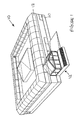
- FIG. 1 and 2 of the drawings there is shown a building 10 according to the invention of rectangular shape in plan view with an entrance 12 on one side. It will be understood that the building could have a shape other than rectangular, for example wedge shaped in plan view, and that more than one entrance may be provided.
- the building 10 has a support frame 14 constructed and arranged to receive a range of pre-fabricated modular units.
- the support frame 14 may be made of steel, timber, glass reinforced plastics, concrete, fibre resin or other suitable materials including combinations of different materials.
- the modular units include pre-fabricated floor modules in the form of panels 16, pre-fabricated room modules 18 and 20, and pre-fabricated roof modules in the form of panels 24 and unit 25.
- the floor panels 16 may be made of concrete, optionally reinforced, although other materials could be used such as resins, glass reinforced plastic, fibres, steel.
- the floor panels 16 slide into openings in the external wall of the support frame 14 on guides or runners (not shown) to form the ground floor of the building 10.
- the perimeters of the floor panels 16 may include a perimeter frame (not shown) to allow the panels to be joined together and sealed if necessary to give a fully finished floor module.
- the floor panels 16 may be adapted for installation of service such as pipework or wiring.
- the floor panels 16 may be formed with channels or ducts to receive the pipework or wiring.
- the floor panels 16 may be fabricated with the services installed.
- the services can be saddled to the underside of the floor supports.
- the floor panels 16 allow the building to be constructed with an open-plan floor area of any desired size and shape. This area can be subdivided if into rooms or smaller areas if desired by partitioning or similar conventional methods.
- the use of floor panels 16 that slide into the support frame 14 provides a simple and effective method of constructing any lay-out of open-plan floor area within the support frame to suit the requirements. Furthermore, the lay-out can be altered and/or extended by removing/replacing/adding floor panels 16, possibly with extensions to the support frame where necessary.
- the room modules 18 are similar to those described in my earlier patent application and are slid into openings in the external wall of the support frame 14 on guides or runners to form an upper floor of the building.
- the room modules 18 may be fitted out according to the intended application of the room.
- Each module 18 may be a self-contained room. Alternatively, two or more adjacent modules 18 may form a single, larger room or suite of rooms.
- the room modules 20 are designed to slide into openings in the external wall of the support frame 14 on the ground floor after insertion of the floor panels 16 and provide a quick and effective method of converting at least some of the open-plan floor area for specific uses.
- the room modules 20 may include pre-installed equipment for the intended application of the room, for example kitchens, restaurants, fridge/freezers, offices, bakeries, shop units, toilets, plant rooms etc.
- Each module 20 may be a self-contained room.
- two or more adjacent modules 20 may form a single, larger room or suite of rooms.
- the room modules 20 can be installed at any desired locations and the lay-out can be altered and/or extended by removing/replacing/adding room modules 20, possibly with extensions to the support frame 14 where necessary.
- Modules 18,20 may arrive complete with any of the following services:-
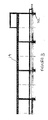
- Figure 3 shows the steel support frame 14 erected on a foundation 22.
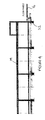
- Figure 4 shows the installation of the floor panels 16 by sliding into in the support frame 14 to form the open plan ground floor area of the building.
- the floor panels 16 can be overlaid to provide any type of floor finish for the intended application thereby achieving a complete uninterrupted monolithic finish, for example vinyl, carpet, wood or the like.
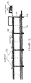
- Figure 5 shows the installation of panels 24 and a glazed unit 25 to form the roof area of the building.
- the panels 24 are lifted and slid into place over the support frame 14 and the glazed unit 25 is lifted and lowered into place by a crane or the like.
- Figure 5 also shows the installation of a room module 18 on the first floor of the building by sliding into the support frame 14.
- the room module 18 may house plant equipment such as an air conditioning unit or may be fitted out for use as an office.
- Figure 6 shows the installation of room modules 20 on the ground floor by sliding into the support frame 14.
- the room modules 20 may be provided for a range of purposes such as kitchens, restaurants, fridge/freezers, offices, bakeries, shop units, toilets, plant rooms etc.
- Figure 6 also shows the provision of a removable canopy 26 attached to the support frame 14 after insertion of the room modules 18 in the first floor.
- removable balconies may be provided, for example where the building is used for living accommodation such as flats or hotels.
- the building is made weathertight on completion by sealing the roof panels 24 and providing a façade to the walls.
- the façade may be in the form of an external skin such as cladding or glazing according to the design of the building.
- the façade is detachable and/or can be opened to allow the modules 16,18,20 to be removed and/or replaced when changing/extending the lay-out of the building.
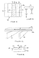
- Figures 7 and 8 show a system for joining the ends of two floor panels 16a,16b.
- the abutting end faces of the panels 16a,16b are joined by one or more rivets 30 or other fastening means.
- the abutting ends of the panels 16a,16b are additionally secured on the underside by one or more clips 36.
- Figure 7 also shows the panels 16a,16b having floor finishes 32a,32b on the upper surface with sealant 34 and edge trim 36 finish therebetween.
- Figures 9 and 10 show a system for joining the sides of two floor panels 16a,16b.
- the adjacent side faces of the panels 16a,16b are joined by male and female formations 38a,38b that allow the panels 16a,16b to slide lengthwise relative to each other.
- the formations are of dovetail shape that prevent the panels 16a,16b separating in a vertical or horizontal direction. It will be understood however that other shapes and configurations of male and female formations may be employed such as rebated side edges.
- the male and female formations 38a,38b again allow the panels 16a,16b to slide lengthwise relative to each other and prevent the panels separating in a horizontal direction but allow one panel to be lifted relative to the other in a vertical direction. This configuration of male and female formations permits the panels 16a,16b to be slid or lowered into place and also allows individual panels 16a,16b to be removed and replaced.
- both Figures show the panels 16a,16b having floor finishes 32a,32b on the upper surface with sealant 34 and edge trim 36 finish therebetween.
- side faces of adjacent panels 16a,16b may be separated by columns of the steel frame.
- the gap between the panels 16a,16b can be filled by inserting an in-fill panel 40 with edge formations 40c configured to mate with the formations on the side faces of the panels 16a,16b so that the in-fill panel 40 can be lowered into place between the floor panels 16a,16b as shown in Figures 11 and 12.
- the in-fill panel 40 has a matching floor finish 40d on its upper surface and sealant 34 and edge trim 36 finish is provided between the panels 16 and the in-fill panel 40.
- an in-fill gasket 41 is provided to fill the gap between the panels 16a,16b and the in-fill panel 40 at the lower edge.
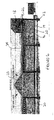
- Figures 13 and 14 show a system for attaching the floor panels 16 to the support frame 14 by means of brackets 42 secured to the underside of the panels 16 and to the support frame 14.
- the brackets 42 are generally Z-shaped with an upper arm 42a received in a sleeve 44 secured to the underside of the panel 16 and a lower arm 42b secured to a bolt 46 attached to the support frame 14.
- Packing 48 may be inserted between the underside of the panel 16 and the support frame 14 to take up any clearance to level the floor and/or to provide sound insulation before tightening a lock nut 50.
- Figure 15 and 16 show a typical lay-out of a floor pan 52 made up of panels 16 and in-fill panels 40 as described above.
- the panels 16 fill the space between upright columns 14a of the support frame 14 and the in-fill panels 40 fill the gaps.
- Panels 16 may come in a range of modular sizes according to the design of the building. For example a single modular panel may cover the floor area between four columns 14a arranged at the corners of the panel as shown in solid lines in Figure 15. Alternatively, the same floor area may be covered by an assembly of two or more interlocking panels 16a,16b as indicated in broken lines in Figure 15.
- a rectangular floor pan 52 is shown, it will be understood that the invention is not limited thereto and that other shapes of floor pan may be constructed employing modular floor panels are described herein.
- one or more of the floor panels may be replaced by a room module having formations co-operable with the adjacent floor panels and/or in-fill panels.
- room modules can be slid or lowered into position in similar manner to the floor panels and/or removed and replaced as desired.
- continuity of floor levels and/or finishes etc can be obtained.
- Figure 17 shows the flat roof panel 24 being slid over the roof beams 60 in the direction of arrow A to the required position.
- the side edges of the panel 24 may be rebated as shown at 24a to overlap a rebated edge of an adjoining panel to improve the joint therebetween as shown in Figure 18.
- the panels 24 may be supplied with a waterproof membrane 62 already attached to the outer surface and with or without membrane flaps 64 for sealing the joints between adjacent panels 24.
- the panel 24 may also be supplied with the inner surface finished with paint or any other lining/ceiling material, wood, plastics, glass reinforced plastics etc.
- the panel 24 may also be configured to receive services similar to the floor panels described previously.
- the services may be located in channels in the panels and may be installed off-site for supply and installation with the roof panels or the services may be installed on-site after the roof panels have been installed.
- service modules may be slung to the underside of the roof panels 24.
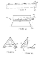
- Figures 19 and 20 show a locking system 61 for attaching the roof panels 24 to the roof beams 60 with no visible fixings.
- the roof beams 60 are provided with headed studs 66 that project from the upper surface and co-operate with sliding wedge packing plates 68 on the underside of the panel 24 to locate and retain the panel 24 in position.
- the panel 24 is lifted into position over the studs 66 and slid into position to tension the studs and secure the panel in position.
- the wedge packing plates 68 may be made of materials to eliminate cold bridging to the structure.
- the locking system 61 may be employed to locate and secure a pitched roof 69 (Figure 21) and a pitched roof 69 and flat roof 70 (Figure 22).
- the roof may be pre-fabricated off-site for supply and installation.
- the pitched roof 69 may incorporate pre-wired solar panels (not sown) or the like and could have pre-installed services within the roof voids, allowing completed sections of the buildings to be delivered and plugged in to adjoining service units.
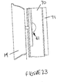
- a similar locking system 61 to that above-described may also be used to secure external wall panels 70 to the support structure 14 as shown in Figure 23.
- the wall panels 70 may be pre-fabricated off-site for supply and installation and may be provided with a suitable waterproof finish 72 on the outer surface to clad the building and with paint or other suitable finish on the inner surface.
- the modular system for floor, roof and wall panels may be employed in some or all areas of a multi-storey building according to the design and use of the building.
- the above systems are inter-changeable.
- the floor pan Z-bracket detail could be employed to retain the composite roof panels or the pitched roof elements depending on the supporting structure design.
- the sliding wedges which secure the roof panels in turn can be used to secure the floor panels and the external building envelope.
- the sliding wedges may be replaced by any other locking systems for attaching the roof panels, floor panels and walls panels.
- the interchangeable power services allow for the installation and removal of electrical services safely without the need of electrical engineers on site and also, for instance, change a data outlet to a socket outlet in the future just by changing the front cover.
- modular systems described herein for constructing the floor, roof and external wall of a building together with the optional provision of room modules within a support frame provides versatility in the design and lay-out of the building as well as the capability to change the design and lay-out by replacing, moving, adding or substituting modules to provide any desired configuration.
Landscapes
- Engineering & Computer Science (AREA)
- Architecture (AREA)
- Civil Engineering (AREA)
- Structural Engineering (AREA)
- Physics & Mathematics (AREA)
- Electromagnetism (AREA)
- Building Environments (AREA)
- Floor Finish (AREA)
Abstract
A modular building comprises a support frame 14 for various modules 16,24,25,70 forming the floor, roof and external wall of the building. The floor is provided by floor modules 16 that can be slid or lifted into place within the support frame 14. Room modules 18,20 may be incorporated into the floor. Services may be installed in the modules.
Description
- This invention concerns improvements in or relating to modular buildings and to a building system for constructing such modular buildings.
- In my
UK patent application No.2415444 - The modules are removably mounted in a frame that provides support for external cladding and roofing of the building to form the weatherproof exterior. The external cladding may be removable to allow access to the modules for removal and insertion of the modules. Accordingly, the necessity for tradesmen to enter the building is greatly reduced because tradesmen can gain access to the modules from the exterior of the building by removing the appropriate cladding.
- The modular construction of my earlier application provides flexibility for the design and construction of buildings for any desired use and enables the building to be adapted to suit changing requirements in a cost effective manner by adding new modules or exchanging existing modules for new modules.
- I have now discovered that the principle of using a modular construction can be extended with advantage to other types of buildings. Thus, in one aspect, the present invention provides a building comprising a support frame and a plurality of prefabricated modules received in the support frame, the modules being floor modules to form a floor and/or roof modules to form a roof.
- Using pre-fabricated modules to form the floor and/or roof of the building produces an open-plan layout that can then be fitted out according to the design requirements of the building by the use of modular rooms as described in my afore-mentioned earlier patent application or by conventional building methods using partition walls to divide up the floor area into different rooms or sections as appropriate. In this way, the floor and roof can be constructed off-site and brought to the site for installation in the support frame by any suitable means.
- The modules may be constructed to facilitate installation of services such as pipework and wiring, for example by the provision of channels or ducts to receive the services. Alternatively or additionally, the modules may be constructed with services built-in.
- The modular system of the invention may be employed in single or multi-storey buildings for any purpose. For example, the invention lends itself to the construction of wide range of different types and sizes of buildings where an open plan area may be employed including, but not limited to, supermarkets, hotels, shopping arcades, airport concourses, laboratories, process plants, hospitals, data and communication buildings, schools, sports facilities, factories and the like.
- From another aspect, the invention provides a method of constructing a building comprising providing a support frame for the building and inserting pre-fabricated modules into the frame to produce a floor and/or roof of desired size and shape.
- The invention will now be described in more detail, by way of example only with reference to the accompanying drawings.
- Figure 1 is a perspective view of a building according to the invention;
- Figure 2 is a perspective view similar to Figure 1 with the external skin removed to show the support frame and modular units;
- Figures 3 to 6 show various stages in the construction of the building shown in Figures 1 and 2;
- Figures 7 to 16 show parts of the modular floor system;
- Figures 17 to 22 show parts of the modular roof system; and
- Figure 23 shows part of a modular wall system.
- Referring to Figures 1 and 2 of the drawings, there is shown a
building 10 according to the invention of rectangular shape in plan view with anentrance 12 on one side. It will be understood that the building could have a shape other than rectangular, for example wedge shaped in plan view, and that more than one entrance may be provided. - The
building 10 has asupport frame 14 constructed and arranged to receive a range of pre-fabricated modular units. Thesupport frame 14 may be made of steel, timber, glass reinforced plastics, concrete, fibre resin or other suitable materials including combinations of different materials. In this embodiment, the modular units include pre-fabricated floor modules in the form ofpanels 16, pre-fabricatedroom modules panels 24 andunit 25. - The
floor panels 16 may be made of concrete, optionally reinforced, although other materials could be used such as resins, glass reinforced plastic, fibres, steel. Thefloor panels 16 slide into openings in the external wall of thesupport frame 14 on guides or runners (not shown) to form the ground floor of thebuilding 10. The perimeters of thefloor panels 16 may include a perimeter frame (not shown) to allow the panels to be joined together and sealed if necessary to give a fully finished floor module. - The
floor panels 16 may be adapted for installation of service such as pipework or wiring. For example, thefloor panels 16 may be formed with channels or ducts to receive the pipework or wiring. Alternatively, thefloor panels 16 may be fabricated with the services installed. Alternatively, the services can be saddled to the underside of the floor supports. - The
floor panels 16 allow the building to be constructed with an open-plan floor area of any desired size and shape. This area can be subdivided if into rooms or smaller areas if desired by partitioning or similar conventional methods. The use offloor panels 16 that slide into thesupport frame 14 provides a simple and effective method of constructing any lay-out of open-plan floor area within the support frame to suit the requirements. Furthermore, the lay-out can be altered and/or extended by removing/replacing/addingfloor panels 16, possibly with extensions to the support frame where necessary. - The
room modules 18 are similar to those described in my earlier patent application and are slid into openings in the external wall of thesupport frame 14 on guides or runners to form an upper floor of the building. Theroom modules 18 may be fitted out according to the intended application of the room. Eachmodule 18 may be a self-contained room. Alternatively, two or moreadjacent modules 18 may form a single, larger room or suite of rooms. - The
room modules 20 are designed to slide into openings in the external wall of thesupport frame 14 on the ground floor after insertion of thefloor panels 16 and provide a quick and effective method of converting at least some of the open-plan floor area for specific uses. For example theroom modules 20 may include pre-installed equipment for the intended application of the room, for example kitchens, restaurants, fridge/freezers, offices, bakeries, shop units, toilets, plant rooms etc. Eachmodule 20 may be a self-contained room. Alternatively, two or moreadjacent modules 20 may form a single, larger room or suite of rooms. Theroom modules 20 can be installed at any desired locations and the lay-out can be altered and/or extended by removing/replacing/addingroom modules 20, possibly with extensions to thesupport frame 14 where necessary. -
Modules - • Building Management Systems (BMS)
- • Main buildings services spine
- • Services inlets, outlets and infrastructure within modules
- • Centralised monitoring and control Building Management Systems (BMS) within their buildings and structures.
- • In addition to a network infrastructure being required, it is anticipated that BMS boxes and interface panels will be generic removable 'plug & play' style devices with varying degrees of functionality that can be tailored to user requirements.
- • All modules may need to be interconnected via a main buildings infrastructure spine and/or services distribution zones. This may be achieved by using "plug and play" devices.
- • Modules could have basic services or even conceive a standard infrastructure cable loom that may be used to build up in series a spine of any length incorporating a style network.
- • Modules could have electrical safeguards such as 'dongle' style devices and software keys so that only compatible modules and systems modules can be used within a building.
- • Services infrastructure within the modules along with provision of input / output devices and interconnectivity to main building service spines may include, but not be limited to, supply of electricity (high and low voltage), telecoms, intranet, cabling, interfaces, coaxial systems together with control interfaces and mechanical circuit breakers along with any systems required by established building standards such as Pyro fire monitoring systems and security systems that may be built in.
- • Using a single composite cable for the most common services power, phone, data, communication devices, monitoring, switching, in conjunction with a generic wall mounted receptacle would allow the fitting of different face plates depending upon which service may be required from a particular outlet point, even lighting units. Using these methods will result in deskilling the installation and maintenance of services within buildings.
- • Additionally interfaces may be required with the building service spine so that modules may be quickly and easily connected / disconnected as they are removed and upgraded or refurbished. Failsafe devices can may be built into the module interconnect solution. Power contacts within connectors to aid the connecting up of modules or lanyard release and stored energy release connectors as safeguards for when removing modules.
- • All wet services including such as water and waste connections will be connected within the units ready to be connected to main service riser or spine.
- Referring now to Figures 3 to 6 of the drawings, various stages in the construction of the building are shown. For convenience, part only of the building is shown. Figure 3 shows the
steel support frame 14 erected on afoundation 22. Figure 4 shows the installation of thefloor panels 16 by sliding into in thesupport frame 14 to form the open plan ground floor area of the building. Thefloor panels 16 can be overlaid to provide any type of floor finish for the intended application thereby achieving a complete uninterrupted monolithic finish, for example vinyl, carpet, wood or the like. - Figure 5 shows the installation of
panels 24 and aglazed unit 25 to form the roof area of the building. Thepanels 24 are lifted and slid into place over thesupport frame 14 and theglazed unit 25 is lifted and lowered into place by a crane or the like. Figure 5 also shows the installation of aroom module 18 on the first floor of the building by sliding into thesupport frame 14. Theroom module 18 may house plant equipment such as an air conditioning unit or may be fitted out for use as an office. - Figure 6 shows the installation of
room modules 20 on the ground floor by sliding into thesupport frame 14. Theroom modules 20 may be provided for a range of purposes such as kitchens, restaurants, fridge/freezers, offices, bakeries, shop units, toilets, plant rooms etc. Figure 6 also shows the provision of aremovable canopy 26 attached to thesupport frame 14 after insertion of theroom modules 18 in the first floor. - For some applications, removable balconies may be provided, for example where the building is used for living accommodation such as flats or hotels. The building is made weathertight on completion by sealing the
roof panels 24 and providing a façade to the walls. The façade may be in the form of an external skin such as cladding or glazing according to the design of the building. The façade is detachable and/or can be opened to allow themodules - Referring now to Figures 7 to 15 of the drawings, various parts of the modular floor system above-described are shown in more detail. For convenience, like reference numerals are used to indicate corresponding parts.
- Figures 7 and 8 show a system for joining the ends of two
floor panels panels more rivets 30 or other fastening means. In Figure 8, the abutting ends of thepanels panels floor finishes sealant 34 and edge trim 36 finish therebetween. - Figures 9 and 10 show a system for joining the sides of two
floor panels panels female formations panels panels female formations panels panels individual panels - In both arrangements, the male and female formations allow loads to be spread between adjacent panels and may reduce the amount of support required for the floor. Both Figures also show the
panels floor finishes sealant 34 and edge trim 36 finish therebetween. In some applications, side faces ofadjacent panels panels fill panel 40 withedge formations 40c configured to mate with the formations on the side faces of thepanels fill panel 40 can be lowered into place between thefloor panels fill panel 40 has amatching floor finish 40d on its upper surface andsealant 34 and edge trim 36 finish is provided between thepanels 16 and the in-fill panel 40. In Figure 11, an in-fill gasket 41 is provided to fill the gap between thepanels fill panel 40 at the lower edge. - Figures 13 and 14 show a system for attaching the
floor panels 16 to thesupport frame 14 by means ofbrackets 42 secured to the underside of thepanels 16 and to thesupport frame 14. As shown thebrackets 42 are generally Z-shaped with anupper arm 42a received in asleeve 44 secured to the underside of thepanel 16 and a lower arm 42b secured to abolt 46 attached to thesupport frame 14.Packing 48 may be inserted between the underside of thepanel 16 and thesupport frame 14 to take up any clearance to level the floor and/or to provide sound insulation before tightening a lock nut 50. - Figure 15 and 16 show a typical lay-out of a
floor pan 52 made up ofpanels 16 and in-fill panels 40 as described above. Thepanels 16 fill the space betweenupright columns 14a of thesupport frame 14 and the in-fill panels 40 fill the gaps.Panels 16 may come in a range of modular sizes according to the design of the building. For example a single modular panel may cover the floor area between fourcolumns 14a arranged at the corners of the panel as shown in solid lines in Figure 15. Alternatively, the same floor area may be covered by an assembly of two ormore interlocking panels rectangular floor pan 52 is shown, it will be understood that the invention is not limited thereto and that other shapes of floor pan may be constructed employing modular floor panels are described herein. - In a modification (not shown), one or more of the floor panels may be replaced by a room module having formations co-operable with the adjacent floor panels and/or in-fill panels. In this way, room modules can be slid or lowered into position in similar manner to the floor panels and/or removed and replaced as desired. Also by incorporating the room module into the floor pan rather than installing the room module on top of the floor pan, continuity of floor levels and/or finishes etc can be obtained.
- Referring now to Figures 17 to 22 of the drawings, various parts of the modular roof system above-described are shown in more detail. For convenience, like reference numerals are used to indicate corresponding parts.
- Figure 17 shows the
flat roof panel 24 being slid over the roof beams 60 in the direction of arrow A to the required position. The side edges of thepanel 24 may be rebated as shown at 24a to overlap a rebated edge of an adjoining panel to improve the joint therebetween as shown in Figure 18. Thepanels 24 may be supplied with awaterproof membrane 62 already attached to the outer surface and with or without membrane flaps 64 for sealing the joints betweenadjacent panels 24. Thepanel 24 may also be supplied with the inner surface finished with paint or any other lining/ceiling material, wood, plastics, glass reinforced plastics etc. Thepanel 24 may also be configured to receive services similar to the floor panels described previously. For example, the services may be located in channels in the panels and may be installed off-site for supply and installation with the roof panels or the services may be installed on-site after the roof panels have been installed. Alternatively, service modules may be slung to the underside of theroof panels 24. - Figures 19 and 20 show a
locking system 61 for attaching theroof panels 24 to the roof beams 60 with no visible fixings. The roof beams 60 are provided with headedstuds 66 that project from the upper surface and co-operate with slidingwedge packing plates 68 on the underside of thepanel 24 to locate and retain thepanel 24 in position. Thepanel 24 is lifted into position over thestuds 66 and slid into position to tension the studs and secure the panel in position. Thewedge packing plates 68 may be made of materials to eliminate cold bridging to the structure. - The locking
system 61 may be employed to locate and secure a pitched roof 69 (Figure 21) and a pitchedroof 69 and flat roof 70 (Figure 22). The roof may be pre-fabricated off-site for supply and installation. The pitchedroof 69 may incorporate pre-wired solar panels (not sown) or the like and could have pre-installed services within the roof voids, allowing completed sections of the buildings to be delivered and plugged in to adjoining service units. - A
similar locking system 61 to that above-described may also be used to secureexternal wall panels 70 to thesupport structure 14 as shown in Figure 23. Thewall panels 70 may be pre-fabricated off-site for supply and installation and may be provided with a suitable waterproof finish 72 on the outer surface to clad the building and with paint or other suitable finish on the inner surface. - It will be understood that the invention is not limited to the embodiments above-described and that various modifications can be made without departing from the principle of a modular system for removably mounting floor, roof and wall panels in a support frame to provide any desired lay-out.
- Thus, the invention has application to single and multi-storey buildings. The modular system for floor, roof and wall panels may be employed in some or all areas of a multi-storey building according to the design and use of the building. The above systems are inter-changeable. For example, the floor pan Z-bracket detail, could be employed to retain the composite roof panels or the pitched roof elements depending on the supporting structure design. The sliding wedges which secure the roof panels in turn can be used to secure the floor panels and the external building envelope. The sliding wedges may be replaced by any other locking systems for attaching the roof panels, floor panels and walls panels. The interchangeable power services allow for the installation and removal of electrical services safely without the need of electrical engineers on site and also, for instance, change a data outlet to a socket outlet in the future just by changing the front cover.
- It will be appreciated that the modular systems described herein for constructing the floor, roof and external wall of a building together with the optional provision of room modules within a support frame provides versatility in the design and lay-out of the building as well as the capability to change the design and lay-out by replacing, moving, adding or substituting modules to provide any desired configuration.
- Other changes that can be made will be apparent to those skilled in the art and the invention is deemed to include all variations and modifications within the scope of the claims.
Claims (13)
- A building comprising a support frame (14) and a plurality of pre-fabricated modules received in the support frame (14), the modules comprising at least one of floor modules (16) to form a floor or roof modules (24,25) to form a roof of the building.
- A building according to claim 1 wherein the modules (16,24,25) are configured for installation of services.
- A building according to claim 1 wherein the modules (16,24,25) are configured to be slid into place in the support frame.
- A building according to claim 1 wherein the modules (16,24,25) are configured to be lifted into place in the support frame.
- A building according to claim 1 wherein the modules comprise panels (16) having edge formations (38a,38b) for locating adjacent panels (16a,16b) relative to each other.
- A building according to claim 1 wherein the modules comprise panels (16) and in-fill panels (40) are provided to close gaps between adjacent panels (16).
- A building according to claim 1 wherein means (42, 61) is provided for securing the modules (16,24,25) to the support frame (14).
- A building according to claim 7 wherein the securing means comprises brackets (42) for attaching an underside of the modules (16) to the support frame (14).
- A building according to claim 7 wherein the securing means comprises wedge packers (68) for attaching an underside of the modules (24,25) to the support frame (14).
- A building according to claim 1 including at least one room module (18,20) received in the support frame (14).
- A building according to claim 10 wherein the room module (20) is provided in place of a floor module (16).
- A building according to claim 1 wherein the modules include wall modules (70) to form an external wall of the building.
- A method of constructing a building comprising providing a support frame (14) for the building and inserting pre-fabricated modules (16,24,25) into the frame (14) to produce a floor and/or roof of desired size and shape.
Applications Claiming Priority (1)
| Application Number | Priority Date | Filing Date | Title |
|---|---|---|---|
| GBGB0619540.8A GB0619540D0 (en) | 2006-10-04 | 2006-10-04 | Improvements in or relating to buildings |
Publications (1)
| Publication Number | Publication Date |
|---|---|
| EP1908888A2 true EP1908888A2 (en) | 2008-04-09 |
Family
ID=37453905
Family Applications (1)
| Application Number | Title | Priority Date | Filing Date |
|---|---|---|---|
| EP07253944A Withdrawn EP1908888A2 (en) | 2006-10-04 | 2007-10-04 | Modular buildings |
Country Status (3)
| Country | Link |
|---|---|
| US (1) | US20080236056A1 (en) |
| EP (1) | EP1908888A2 (en) |
| GB (2) | GB0619540D0 (en) |
Families Citing this family (12)
| Publication number | Priority date | Publication date | Assignee | Title |
|---|---|---|---|---|
| US20090229194A1 (en) * | 2008-03-11 | 2009-09-17 | Advanced Shielding Technologies Europe S.I. | Portable modular data center |
| CN101994405A (en) * | 2009-08-12 | 2011-03-30 | 鸿富锦精密工业(深圳)有限公司 | houses |
| CN101994406A (en) * | 2009-08-12 | 2011-03-30 | 鸿富锦精密工业(深圳)有限公司 | House |
| US9198331B2 (en) * | 2013-03-15 | 2015-11-24 | Switch, Ltd. | Data center facility design configuration |
| CA2911779A1 (en) * | 2014-11-12 | 2016-05-12 | Newterra Ltd | Intermodal container building structures and methods |
| US10011982B1 (en) * | 2015-09-23 | 2018-07-03 | Theodore W. Baker | School spaces retrofitted for alternative uses and related technology |
| US9914467B2 (en) | 2015-08-14 | 2018-03-13 | Oldcastle Light Building Products, LLC | Attachment and support members for modular building structures |
| US10344487B2 (en) | 2015-08-14 | 2019-07-09 | Oldcastle Light Building Products, LLC | Attachment and support members for modular building structures |
| US20190032327A1 (en) * | 2017-07-31 | 2019-01-31 | Brent Musson | Permanent building structure with reusable modular building units |
| US11623428B2 (en) * | 2021-07-30 | 2023-04-11 | United States Government As Represented By The Secretary Of The Army | Load-bearing composite platform |
| US20230160196A1 (en) * | 2021-11-23 | 2023-05-25 | Optima, Inc. | Modular habitable structures, and associated systems and methods |
| US12291858B2 (en) | 2023-01-31 | 2025-05-06 | Topk USA LLC | Modular assembly including multiple modules |
Family Cites Families (9)
| Publication number | Priority date | Publication date | Assignee | Title |
|---|---|---|---|---|
| US4012871A (en) * | 1971-10-26 | 1977-03-22 | Acacia Engenharia Industria E Commercio | Modular housing units |
| US6457281B1 (en) * | 1980-06-24 | 2002-10-01 | Teron International Building Technologies Ltd. | Modular building systems |
| US4910932A (en) * | 1987-01-05 | 1990-03-27 | Honigman Michael L | Modular building system |
| US4833855A (en) * | 1987-04-27 | 1989-05-30 | Winter Amos G Iv | Prefabricated panel having a joint thereon |
| US5555681A (en) * | 1995-07-06 | 1996-09-17 | Cawthon; Mark A. | Modular building system |
| GB2350130B (en) * | 1999-05-21 | 2001-08-15 | Ashley Thomas Beighton | Improvements in or relating to building structures |
| US6651393B2 (en) * | 2001-05-15 | 2003-11-25 | Lorwood Properties, Inc. | Construction system for manufactured housing units |
| DE20312406U1 (en) * | 2003-08-07 | 2003-10-09 | Rüter, Ewald, 44229 Dortmund | Modular steel framework building system has two outer frames linked by cross members with end wedges locating onto corresponding sockets on the side frame vertical struts |
| US20070283634A1 (en) * | 2006-05-23 | 2007-12-13 | Hourihan Kevin J | Lifting Cradle |
-
2006
- 2006-10-04 GB GBGB0619540.8A patent/GB0619540D0/en not_active Ceased
-
2007
- 2007-10-03 US US11/866,702 patent/US20080236056A1/en not_active Abandoned
- 2007-10-04 GB GB0719417A patent/GB2442606A/en not_active Withdrawn
- 2007-10-04 EP EP07253944A patent/EP1908888A2/en not_active Withdrawn
Also Published As
| Publication number | Publication date |
|---|---|
| GB0619540D0 (en) | 2006-11-15 |
| US20080236056A1 (en) | 2008-10-02 |
| GB0719417D0 (en) | 2007-11-14 |
| GB2442606A (en) | 2008-04-09 |
Similar Documents
| Publication | Publication Date | Title |
|---|---|---|
| EP1908888A2 (en) | Modular buildings | |
| US3712007A (en) | Building system and components therefor | |
| CN104204372B (en) | Method and system for construction of a building | |
| US20130305629A1 (en) | Modular Building System | |
| US20160040443A1 (en) | Modular Building System | |
| RU2628352C2 (en) | Prefabricated module for building | |
| US20160319534A1 (en) | Reversible module co-ordination system for buildings | |
| US9828761B2 (en) | Building system | |
| EP0128777A2 (en) | Transportable building modules and building structures incorporating such modules | |
| GB2350130A (en) | Building comprising independently cantilevered modules | |
| WO2015071821A1 (en) | Modular prefabricated panel for buildings, in particular for houses | |
| WO2022067416A1 (en) | Method for assembling a modular building | |
| WO2013171772A1 (en) | Modular-based, concrete floor or roofing building structure | |
| CN104736777B (en) | Building system, in particular residential building | |
| US20050144857A1 (en) | Modular building system | |
| US20240271411A1 (en) | Modular building having a supporting structure which encloses an interior space | |
| US20160122997A1 (en) | Transportable Unitized Modular Construction | |
| EP1196668B1 (en) | Building system | |
| US20240011276A1 (en) | Modular building structure | |
| JPH06158878A (en) | Dwelling unit variable housing system | |
| BRPI1103773A2 (en) | constructive process of modular units and modular units thus obtained | |
| WO2017134241A1 (en) | Method of assembling a residential structure | |
| EA041217B1 (en) | MODULAR BUILDING ASSEMBLY METHOD | |
| WO2025238167A1 (en) | Building, modular building assembly and method of providing services | |
| KR20020054140A (en) | Light-weight wall system |
Legal Events
| Date | Code | Title | Description |
|---|---|---|---|
| PUAI | Public reference made under article 153(3) epc to a published international application that has entered the european phase |
Free format text: ORIGINAL CODE: 0009012 |
|
| AK | Designated contracting states |
Kind code of ref document: A2 Designated state(s): AT BE BG CH CY CZ DE DK EE ES FI FR GB GR HU IE IS IT LI LT LU LV MC MT NL PL PT RO SE SI SK TR |
|
| AX | Request for extension of the european patent |
Extension state: AL BA HR MK RS |
|
| STAA | Information on the status of an ep patent application or granted ep patent |
Free format text: STATUS: THE APPLICATION IS DEEMED TO BE WITHDRAWN |
|
| 18D | Application deemed to be withdrawn |
Effective date: 20100504 |