EP1908704A1 - Ausflussdüse - Google Patents
Ausflussdüse Download PDFInfo
- Publication number
- EP1908704A1 EP1908704A1 EP07117760A EP07117760A EP1908704A1 EP 1908704 A1 EP1908704 A1 EP 1908704A1 EP 07117760 A EP07117760 A EP 07117760A EP 07117760 A EP07117760 A EP 07117760A EP 1908704 A1 EP1908704 A1 EP 1908704A1
- Authority
- EP
- European Patent Office
- Prior art keywords
- duct
- dispensing
- groove
- outflow nozzle
- spray
- Prior art date
- Legal status (The legal status is an assumption and is not a legal conclusion. Google has not performed a legal analysis and makes no representation as to the accuracy of the status listed.)
- Granted
Links
Images
Classifications
-
- B—PERFORMING OPERATIONS; TRANSPORTING
- B29—WORKING OF PLASTICS; WORKING OF SUBSTANCES IN A PLASTIC STATE IN GENERAL
- B29C—SHAPING OR JOINING OF PLASTICS; SHAPING OF MATERIAL IN A PLASTIC STATE, NOT OTHERWISE PROVIDED FOR; AFTER-TREATMENT OF THE SHAPED PRODUCTS, e.g. REPAIRING
- B29C45/00—Injection moulding, i.e. forcing the required volume of moulding material through a nozzle into a closed mould; Apparatus therefor
- B29C45/17—Component parts, details or accessories; Auxiliary operations
- B29C45/26—Moulds
- B29C45/2628—Moulds with mould parts forming holes in or through the moulded article, e.g. for bearing cages
-
- B—PERFORMING OPERATIONS; TRANSPORTING
- B65—CONVEYING; PACKING; STORING; HANDLING THIN OR FILAMENTARY MATERIAL
- B65D—CONTAINERS FOR STORAGE OR TRANSPORT OF ARTICLES OR MATERIALS, e.g. BAGS, BARRELS, BOTTLES, BOXES, CANS, CARTONS, CRATES, DRUMS, JARS, TANKS, HOPPERS, FORWARDING CONTAINERS; ACCESSORIES, CLOSURES, OR FITTINGS THEREFOR; PACKAGING ELEMENTS; PACKAGES
- B65D83/00—Containers or packages with special means for dispensing contents
- B65D83/14—Containers for dispensing liquid or semi-liquid contents by internal gaseous pressure, i.e. aerosol containers comprising propellant
- B65D83/16—Actuating means
- B65D83/20—Actuator caps
-
- B—PERFORMING OPERATIONS; TRANSPORTING
- B65—CONVEYING; PACKING; STORING; HANDLING THIN OR FILAMENTARY MATERIAL
- B65D—CONTAINERS FOR STORAGE OR TRANSPORT OF ARTICLES OR MATERIALS, e.g. BAGS, BARRELS, BOTTLES, BOXES, CANS, CARTONS, CRATES, DRUMS, JARS, TANKS, HOPPERS, FORWARDING CONTAINERS; ACCESSORIES, CLOSURES, OR FITTINGS THEREFOR; PACKAGING ELEMENTS; PACKAGES
- B65D83/00—Containers or packages with special means for dispensing contents
- B65D83/14—Containers for dispensing liquid or semi-liquid contents by internal gaseous pressure, i.e. aerosol containers comprising propellant
- B65D83/28—Nozzles, nozzle fittings or accessories specially adapted therefor
- B65D83/30—Nozzles, nozzle fittings or accessories specially adapted therefor for guiding the flow of the dispensed content, e.g. funnels or hoods
- B65D83/306—Actuators formed as a rigid elongate spout
Definitions
- the present invention relates to an outflow nozzle according to the preamble of claim 1.
- a helical groove is provided in the wall of the duct which extends between the dispensing sleeve of the spray can and the dispensing nozzle.
- two or more grooves of this type are provided in an evenly distributed manner along the periphery of the duct. These grooves exert in longitudinal direction of the duct, that is to say that the longitudinal centre axis of the grooves is substantially parallel with the longitudinal centre axis of the duct.
- the ducts are shaped in the form of a helix with respect to said longitudinal centre axis in order to impart turbulence to the fluid. If various grooves are used, the turbulence caused by each of the grooves is preferably the same. As a result thereof, the fluid is made to rotate which results in a turbulence which is such that gas bubbles can be produced in a simple and controlled manner.
- the degree of curvature of the groove is preferably the same over its entire length. This makes it possible to determine a pitch and preferably the length of the groove is at least a quarter of the pitch, that is to say that between the start and the end, the groove turns with respect to the longitudinal axis of the duct by at least 90°.
- the duct tapers between the receiving end on the spray can and the dispensing opening.
- the duct tapers in an continuous manner.
- the shape of the groove preferably changes between the receiving end and the dispensing opening.
- the width of the duct decreases in the direction of the dispensing opening.
- the depth of the groove increases in the direction of the dispensing opening. More particularly, the entire cross-sectional surface of the groove is preferably substantially constant along its entire length.
- the dispensing nozzle forms an integral part of the dispensing opening, that is to say that it consists of one plastic component. No further plastic component is required so that, when the outflow nozzle is placed on the spray can, the latter is ready to use (except for a protective cover, if desired).
- the outflow nozzle may form an integral part of a protective cover or cap of the spray can.
- the invention also relates to a method for producing the above-described outflow nozzle by means of injection-moulding, in which the core moves in and out of the mould cavity along the longitudinal centre axis, as described above, wherein the article produced can be removed without deformation thereof.
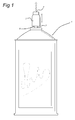
- a spray can is denoted by reference numeral 1. It should be understood that the embodiment of the spray can is immaterial in the context of the invention.
- This spray can is provided with a dispensing sleeve 2 which dispenses a fluid from the spray can 1 when a valve construction (not shown) is pressed.
- the outflow nozzle 3 of the present invention which is provided with a dispensing opening 4 is placed on said dispensing sleeve.
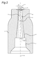
- the outflow nozzle 3 has a cylindrical part 7 with an opening 9 for receiving the dispensing sleeve 2, preferably in a clamping manner, which is adjoined by a duct 6.
- the adjoining dispensing opening 4 is designed as an outflow nozzle and to this end is provided with a dispensing passage 5.
- the present invention relates in particular to the design of the duct 6, which is provided with grooves 8 having a centre axis 11.
- the centre axis of the duct 6 is denoted by reference numeral 10.
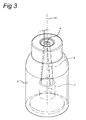
- Figs. 2 and 3 show that the grooves extend around this centre axis 10 in the shape of a helix at a relatively large pitch.
- the width of the grooves decreases in the direction of the dispensing opening 4. This width is denoted by reference numeral b 1 on the side of the cylindrical part 7 and by reference numeral b2 on the side of the dispensing opening 4.
- the situation with regard to the depth of the grooves 8 is exactly the opposite.
- the depth at the cylindrical part 7 is denoted by reference numeral d1 and is relatively small, while the depth at the dispensing opening 4 is denoted by reference numeral d2 and is relatively large.
- the cross-sectional area which is determined by w x d along the length of the groove decreases substantially evenly.
- the fluid will be compressed in the direction of the dispensing nozzle. Vapour bubbles resulting from expansion immediately after introduction into the duct 6 are compressed again. In combination with the turbulence, this compression leads to a finer distribution of the vapour bubbles in the fluid and results in a finer atomization at the dispensing nozzle.
- the detachable design of the core part can be simplified further.
- preferably at least two grooves 8 are provided opposite one another.
- Fig. 3 shows that this number can be greater.
- the design and position of the grooves is such that they can be produced in a very simple manner, together with the duct 6, when the dispensing nozzle is formed.
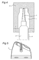
- an injection mould part which is denoted by reference numeral 20
- the boundary surface of the recess corresponds to the outer surface of the outflow nozzle.
- a core 21 is placed in the mould during injection-moulding so that this space cannot be filled with plastic, resulting in the duct and grooves.
- This core 21 has ribs 23 which match the grooves which are formed later. According to the invention, this core 21 can only be displaced in the direction of the arrow 22. That is to say that the grooves, in combination with the taper of the duct, are designed in such a manner that no rotary movement is necessary to remove the core 21 and an exact linear translational movement along arrow 22 is sufficient to remove the core 21 from the mould 20, without deformation near the grooves occurring.
- the dispensing nozzle or the dispensing opening By additionally forming the dispensing nozzle or the dispensing opening as an integral part of the outflow nozzle, a further separate part can be omitted, resulting in a further saving due to the number of assembling operations being reduced.
- no part, such as a pin or the like, is used in the duct and the duct is completely free.
- Fig. 5 shows how the outflow nozzle is formed as an integral part of a cap 31 for a spray can.
- the illustrated part is produced solely by injection-moulding.
Landscapes
- Engineering & Computer Science (AREA)
- Mechanical Engineering (AREA)
- Chemical & Material Sciences (AREA)
- Dispersion Chemistry (AREA)
- Manufacturing & Machinery (AREA)
- Nozzles (AREA)
- Containers And Packaging Bodies Having A Special Means To Remove Contents (AREA)
- Percussion Or Vibration Massage (AREA)
- Polarising Elements (AREA)
Applications Claiming Priority (1)
| Application Number | Priority Date | Filing Date | Title |
|---|---|---|---|
| NL2000254A NL2000254C2 (nl) | 2006-10-02 | 2006-10-02 | Uitstroommondstuk. |
Publications (2)
| Publication Number | Publication Date |
|---|---|
| EP1908704A1 true EP1908704A1 (de) | 2008-04-09 |
| EP1908704B1 EP1908704B1 (de) | 2010-07-07 |
Family
ID=37946747
Family Applications (1)
| Application Number | Title | Priority Date | Filing Date |
|---|---|---|---|
| EP07117760A Active EP1908704B1 (de) | 2006-10-02 | 2007-10-02 | Ausflussdüse |
Country Status (4)
| Country | Link |
|---|---|
| EP (1) | EP1908704B1 (de) |
| AT (1) | ATE473187T1 (de) |
| DE (1) | DE602007007556D1 (de) |
| NL (1) | NL2000254C2 (de) |
Cited By (2)
| Publication number | Priority date | Publication date | Assignee | Title |
|---|---|---|---|---|
| WO2009129180A1 (en) * | 2008-04-15 | 2009-10-22 | Seymour Of Sycamore, Inc. | Insert for inverted spray nozzle |
| KR20240153124A (ko) * | 2023-04-14 | 2024-10-22 | 원광대학교산학협력단 | 배출구 캡이 보완된 배액 주머니 |
Citations (7)
| Publication number | Priority date | Publication date | Assignee | Title |
|---|---|---|---|---|
| GB828160A (en) * | 1955-08-11 | 1960-02-17 | Franco Galeazzi | Device for spraying liquids by means of a volatile propellant |
| US2962228A (en) * | 1956-11-08 | 1960-11-29 | Precision Valve Corp | Valve operating button for dispensing pressurized material and die for forming the same |
| US3578221A (en) * | 1968-03-06 | 1971-05-11 | Schwarzkopf Fa Hans | Aerosol container with push-on closure and nozzle |
| US3710990A (en) * | 1970-06-01 | 1973-01-16 | S Lazarus | Aerosol type dispenser |
| US3838822A (en) * | 1970-09-23 | 1974-10-01 | R Ewald | Valve button |
| EP0798233A2 (de) * | 1996-03-29 | 1997-10-01 | Coster Tecnologie Speciali S.P.A. | Ventil für die Abgabe von unter Druck stehenden Fluiden |
| EP1029807A1 (de) * | 1999-02-15 | 2000-08-23 | Silvano Foconetti | Zerstäuberkappe für Sprühdose |
-
2006
- 2006-10-02 NL NL2000254A patent/NL2000254C2/nl not_active IP Right Cessation
-
2007
- 2007-10-02 AT AT07117760T patent/ATE473187T1/de not_active IP Right Cessation
- 2007-10-02 DE DE602007007556T patent/DE602007007556D1/de active Active
- 2007-10-02 EP EP07117760A patent/EP1908704B1/de active Active
Patent Citations (7)
| Publication number | Priority date | Publication date | Assignee | Title |
|---|---|---|---|---|
| GB828160A (en) * | 1955-08-11 | 1960-02-17 | Franco Galeazzi | Device for spraying liquids by means of a volatile propellant |
| US2962228A (en) * | 1956-11-08 | 1960-11-29 | Precision Valve Corp | Valve operating button for dispensing pressurized material and die for forming the same |
| US3578221A (en) * | 1968-03-06 | 1971-05-11 | Schwarzkopf Fa Hans | Aerosol container with push-on closure and nozzle |
| US3710990A (en) * | 1970-06-01 | 1973-01-16 | S Lazarus | Aerosol type dispenser |
| US3838822A (en) * | 1970-09-23 | 1974-10-01 | R Ewald | Valve button |
| EP0798233A2 (de) * | 1996-03-29 | 1997-10-01 | Coster Tecnologie Speciali S.P.A. | Ventil für die Abgabe von unter Druck stehenden Fluiden |
| EP1029807A1 (de) * | 1999-02-15 | 2000-08-23 | Silvano Foconetti | Zerstäuberkappe für Sprühdose |
Cited By (4)
| Publication number | Priority date | Publication date | Assignee | Title |
|---|---|---|---|---|
| WO2009129180A1 (en) * | 2008-04-15 | 2009-10-22 | Seymour Of Sycamore, Inc. | Insert for inverted spray nozzle |
| US8550382B2 (en) | 2008-04-15 | 2013-10-08 | Seymour Of Sycamore Inc. | Insert for inverted spray nozzle |
| KR20240153124A (ko) * | 2023-04-14 | 2024-10-22 | 원광대학교산학협력단 | 배출구 캡이 보완된 배액 주머니 |
| KR102908784B1 (ko) | 2023-04-14 | 2026-01-07 | 원광대학교산학협력단 | 배출구 캡이 보완된 배액 주머니 |
Also Published As
| Publication number | Publication date |
|---|---|
| HK1115850A1 (en) | 2008-12-12 |
| ATE473187T1 (de) | 2010-07-15 |
| DE602007007556D1 (de) | 2010-08-19 |
| NL2000254C2 (nl) | 2008-04-08 |
| EP1908704B1 (de) | 2010-07-07 |
Similar Documents
| Publication | Publication Date | Title |
|---|---|---|
| CN107000284B (zh) | 一种弹性元件以及用于制造所述弹性元件的方法和铸模 | |
| US8925836B2 (en) | Gravity cup for a paint sprayer | |
| CN102211070B (zh) | 用于将进料装置连接在喷枪上的连接件 | |
| US4733801A (en) | Method of and means for manufacture of a dispenser for viscous or semi-viscous materials | |
| MY154153A (en) | Method of manufacturing hollow body | |
| RU2585282C2 (ru) | Пластмассовое изделие и технологическая установка для изготовления пластмассового изделия | |
| WO2002055200A1 (en) | Pipette tip for easy mounting and ejecting from a pipette | |
| JP6993431B2 (ja) | ディスペンサ容器 | |
| US20190366376A1 (en) | Method for producing a guiding rod for a pump | |
| EP1786614A1 (de) | Verfahren zur herstellung einer kunststoffflasche, dafür geeigneter preform und blasform | |
| EP1908704B1 (de) | Ausflussdüse | |
| EP3375722B1 (de) | Glasflasche | |
| EP2583904B1 (de) | Behälter mit aufgeklappter Rückwand | |
| HK1115850B (en) | Outflow nozzle | |
| US7021920B2 (en) | Method and apparatus for blow molding a bottle with a punched hole in a molded neck recess | |
| US20230249200A1 (en) | Spray head and device for dispensing a fluid product comprising such a head | |
| JPH09155933A (ja) | 樹脂製伸縮ノズルおよび長尺中空材の射出成型方法 | |
| DE3835680C2 (de) | ||
| KR101378559B1 (ko) | 플라스틱 물품을 압축 성형하기 위한 장치 및 방법 | |
| US20100266978A1 (en) | Plastic capsule for the storage and delivery of flowable dental materials and applicator to contain them | |
| CN104640777A (zh) | 用于化妆的或制药的液体的分配器 | |
| CN1810181B (zh) | 涂抹器杆 | |
| US20180093293A1 (en) | Disposable nozzle for an applicator for applying resin to the inside of a pre-creased garment or a piece of fabric | |
| US20220410185A1 (en) | Method for producing a distribution wall | |
| US20240091057A1 (en) | Fluid dispenser and method for manufacturing a fluid dispenser |
Legal Events
| Date | Code | Title | Description |
|---|---|---|---|
| PUAI | Public reference made under article 153(3) epc to a published international application that has entered the european phase |
Free format text: ORIGINAL CODE: 0009012 |
|
| AK | Designated contracting states |
Kind code of ref document: A1 Designated state(s): AT BE BG CH CY CZ DE DK EE ES FI FR GB GR HU IE IS IT LI LT LU LV MC MT NL PL PT RO SE SI SK TR |
|
| AX | Request for extension of the european patent |
Extension state: AL BA HR MK RS |
|
| 17P | Request for examination filed |
Effective date: 20081009 |
|
| REG | Reference to a national code |
Ref country code: HK Ref legal event code: DE Ref document number: 1115850 Country of ref document: HK |
|
| AKX | Designation fees paid |
Designated state(s): AT BE BG CH CY CZ DE DK EE ES FI FR GB GR HU IE IS IT LI LT LU LV MC MT NL PL PT RO SE SI SK TR |
|
| 17Q | First examination report despatched |
Effective date: 20041210 |
|
| R17C | First examination report despatched (corrected) |
Effective date: 20081210 |
|
| GRAP | Despatch of communication of intention to grant a patent |
Free format text: ORIGINAL CODE: EPIDOSNIGR1 |
|
| GRAS | Grant fee paid |
Free format text: ORIGINAL CODE: EPIDOSNIGR3 |
|
| GRAA | (expected) grant |
Free format text: ORIGINAL CODE: 0009210 |
|
| AK | Designated contracting states |
Kind code of ref document: B1 Designated state(s): AT BE BG CH CY CZ DE DK EE ES FI FR GB GR HU IE IS IT LI LT LU LV MC MT NL PL PT RO SE SI SK TR |
|
| REG | Reference to a national code |
Ref country code: GB Ref legal event code: FG4D |
|
| REG | Reference to a national code |
Ref country code: CH Ref legal event code: EP |
|
| REG | Reference to a national code |
Ref country code: IE Ref legal event code: FG4D |
|
| REF | Corresponds to: |
Ref document number: 602007007556 Country of ref document: DE Date of ref document: 20100819 Kind code of ref document: P |
|
| REG | Reference to a national code |
Ref country code: HK Ref legal event code: GR Ref document number: 1115850 Country of ref document: HK |
|
| REG | Reference to a national code |
Ref country code: NL Ref legal event code: T3 |
|
| PG25 | Lapsed in a contracting state [announced via postgrant information from national office to epo] |
Ref country code: SI Free format text: LAPSE BECAUSE OF FAILURE TO SUBMIT A TRANSLATION OF THE DESCRIPTION OR TO PAY THE FEE WITHIN THE PRESCRIBED TIME-LIMIT Effective date: 20100707 |
|
| LTIE | Lt: invalidation of european patent or patent extension |
Effective date: 20100707 |
|
| PG25 | Lapsed in a contracting state [announced via postgrant information from national office to epo] |
Ref country code: LT Free format text: LAPSE BECAUSE OF FAILURE TO SUBMIT A TRANSLATION OF THE DESCRIPTION OR TO PAY THE FEE WITHIN THE PRESCRIBED TIME-LIMIT Effective date: 20100707 Ref country code: FI Free format text: LAPSE BECAUSE OF FAILURE TO SUBMIT A TRANSLATION OF THE DESCRIPTION OR TO PAY THE FEE WITHIN THE PRESCRIBED TIME-LIMIT Effective date: 20100707 Ref country code: AT Free format text: LAPSE BECAUSE OF FAILURE TO SUBMIT A TRANSLATION OF THE DESCRIPTION OR TO PAY THE FEE WITHIN THE PRESCRIBED TIME-LIMIT Effective date: 20100707 |
|
| PG25 | Lapsed in a contracting state [announced via postgrant information from national office to epo] |
Ref country code: IS Free format text: LAPSE BECAUSE OF FAILURE TO SUBMIT A TRANSLATION OF THE DESCRIPTION OR TO PAY THE FEE WITHIN THE PRESCRIBED TIME-LIMIT Effective date: 20101107 Ref country code: PT Free format text: LAPSE BECAUSE OF FAILURE TO SUBMIT A TRANSLATION OF THE DESCRIPTION OR TO PAY THE FEE WITHIN THE PRESCRIBED TIME-LIMIT Effective date: 20101108 Ref country code: BG Free format text: LAPSE BECAUSE OF FAILURE TO SUBMIT A TRANSLATION OF THE DESCRIPTION OR TO PAY THE FEE WITHIN THE PRESCRIBED TIME-LIMIT Effective date: 20101007 Ref country code: PL Free format text: LAPSE BECAUSE OF FAILURE TO SUBMIT A TRANSLATION OF THE DESCRIPTION OR TO PAY THE FEE WITHIN THE PRESCRIBED TIME-LIMIT Effective date: 20100707 Ref country code: CY Free format text: LAPSE BECAUSE OF FAILURE TO SUBMIT A TRANSLATION OF THE DESCRIPTION OR TO PAY THE FEE WITHIN THE PRESCRIBED TIME-LIMIT Effective date: 20100707 |
|
| PG25 | Lapsed in a contracting state [announced via postgrant information from national office to epo] |
Ref country code: BE Free format text: LAPSE BECAUSE OF FAILURE TO SUBMIT A TRANSLATION OF THE DESCRIPTION OR TO PAY THE FEE WITHIN THE PRESCRIBED TIME-LIMIT Effective date: 20100707 Ref country code: LV Free format text: LAPSE BECAUSE OF FAILURE TO SUBMIT A TRANSLATION OF THE DESCRIPTION OR TO PAY THE FEE WITHIN THE PRESCRIBED TIME-LIMIT Effective date: 20100707 Ref country code: GR Free format text: LAPSE BECAUSE OF FAILURE TO SUBMIT A TRANSLATION OF THE DESCRIPTION OR TO PAY THE FEE WITHIN THE PRESCRIBED TIME-LIMIT Effective date: 20101008 Ref country code: SE Free format text: LAPSE BECAUSE OF FAILURE TO SUBMIT A TRANSLATION OF THE DESCRIPTION OR TO PAY THE FEE WITHIN THE PRESCRIBED TIME-LIMIT Effective date: 20100707 |
|
| PG25 | Lapsed in a contracting state [announced via postgrant information from national office to epo] |
Ref country code: DK Free format text: LAPSE BECAUSE OF FAILURE TO SUBMIT A TRANSLATION OF THE DESCRIPTION OR TO PAY THE FEE WITHIN THE PRESCRIBED TIME-LIMIT Effective date: 20100707 |
|
| PLBE | No opposition filed within time limit |
Free format text: ORIGINAL CODE: 0009261 |
|
| STAA | Information on the status of an ep patent application or granted ep patent |
Free format text: STATUS: NO OPPOSITION FILED WITHIN TIME LIMIT |
|
| PG25 | Lapsed in a contracting state [announced via postgrant information from national office to epo] |
Ref country code: SK Free format text: LAPSE BECAUSE OF FAILURE TO SUBMIT A TRANSLATION OF THE DESCRIPTION OR TO PAY THE FEE WITHIN THE PRESCRIBED TIME-LIMIT Effective date: 20100707 Ref country code: EE Free format text: LAPSE BECAUSE OF FAILURE TO SUBMIT A TRANSLATION OF THE DESCRIPTION OR TO PAY THE FEE WITHIN THE PRESCRIBED TIME-LIMIT Effective date: 20100707 Ref country code: RO Free format text: LAPSE BECAUSE OF FAILURE TO SUBMIT A TRANSLATION OF THE DESCRIPTION OR TO PAY THE FEE WITHIN THE PRESCRIBED TIME-LIMIT Effective date: 20100707 Ref country code: MC Free format text: LAPSE BECAUSE OF NON-PAYMENT OF DUE FEES Effective date: 20101031 Ref country code: CZ Free format text: LAPSE BECAUSE OF FAILURE TO SUBMIT A TRANSLATION OF THE DESCRIPTION OR TO PAY THE FEE WITHIN THE PRESCRIBED TIME-LIMIT Effective date: 20100707 |
|
| 26N | No opposition filed |
Effective date: 20110408 |
|
| PG25 | Lapsed in a contracting state [announced via postgrant information from national office to epo] |
Ref country code: ES Free format text: LAPSE BECAUSE OF FAILURE TO SUBMIT A TRANSLATION OF THE DESCRIPTION OR TO PAY THE FEE WITHIN THE PRESCRIBED TIME-LIMIT Effective date: 20101018 |
|
| REG | Reference to a national code |
Ref country code: DE Ref legal event code: R097 Ref document number: 602007007556 Country of ref document: DE Effective date: 20110408 |
|
| PG25 | Lapsed in a contracting state [announced via postgrant information from national office to epo] |
Ref country code: IE Free format text: LAPSE BECAUSE OF NON-PAYMENT OF DUE FEES Effective date: 20101002 |
|
| PG25 | Lapsed in a contracting state [announced via postgrant information from national office to epo] |
Ref country code: IT Free format text: LAPSE BECAUSE OF NON-PAYMENT OF DUE FEES Effective date: 20101002 Ref country code: MT Free format text: LAPSE BECAUSE OF FAILURE TO SUBMIT A TRANSLATION OF THE DESCRIPTION OR TO PAY THE FEE WITHIN THE PRESCRIBED TIME-LIMIT Effective date: 20100707 |
|
| REG | Reference to a national code |
Ref country code: CH Ref legal event code: PL |
|
| PG25 | Lapsed in a contracting state [announced via postgrant information from national office to epo] |
Ref country code: CH Free format text: LAPSE BECAUSE OF NON-PAYMENT OF DUE FEES Effective date: 20111031 Ref country code: LI Free format text: LAPSE BECAUSE OF NON-PAYMENT OF DUE FEES Effective date: 20111031 |
|
| PG25 | Lapsed in a contracting state [announced via postgrant information from national office to epo] |
Ref country code: HU Free format text: LAPSE BECAUSE OF FAILURE TO SUBMIT A TRANSLATION OF THE DESCRIPTION OR TO PAY THE FEE WITHIN THE PRESCRIBED TIME-LIMIT Effective date: 20110108 Ref country code: LU Free format text: LAPSE BECAUSE OF NON-PAYMENT OF DUE FEES Effective date: 20101002 |
|
| PG25 | Lapsed in a contracting state [announced via postgrant information from national office to epo] |
Ref country code: TR Free format text: LAPSE BECAUSE OF FAILURE TO SUBMIT A TRANSLATION OF THE DESCRIPTION OR TO PAY THE FEE WITHIN THE PRESCRIBED TIME-LIMIT Effective date: 20100707 |
|
| REG | Reference to a national code |
Ref country code: FR Ref legal event code: PLFP Year of fee payment: 9 |
|
| REG | Reference to a national code |
Ref country code: GB Ref legal event code: 732E Free format text: REGISTERED BETWEEN 20160303 AND 20160309 |
|
| REG | Reference to a national code |
Ref country code: GB Ref legal event code: 732E Free format text: REGISTERED BETWEEN 20160324 AND 20160330 |
|
| REG | Reference to a national code |
Ref country code: FR Ref legal event code: PLFP Year of fee payment: 10 |
|
| REG | Reference to a national code |
Ref country code: FR Ref legal event code: PLFP Year of fee payment: 11 |
|
| REG | Reference to a national code |
Ref country code: FR Ref legal event code: PLFP Year of fee payment: 12 |
|
| P01 | Opt-out of the competence of the unified patent court (upc) registered |
Effective date: 20230517 |
|
| PGFP | Annual fee paid to national office [announced via postgrant information from national office to epo] |
Ref country code: NL Payment date: 20251026 Year of fee payment: 19 |
|
| PGFP | Annual fee paid to national office [announced via postgrant information from national office to epo] |
Ref country code: DE Payment date: 20251029 Year of fee payment: 19 |
|
| PGFP | Annual fee paid to national office [announced via postgrant information from national office to epo] |
Ref country code: GB Payment date: 20251027 Year of fee payment: 19 |
|
| PGFP | Annual fee paid to national office [announced via postgrant information from national office to epo] |
Ref country code: IT Payment date: 20251021 Year of fee payment: 19 |
|
| PGFP | Annual fee paid to national office [announced via postgrant information from national office to epo] |
Ref country code: FR Payment date: 20251027 Year of fee payment: 19 |