EP1908671B1 - Driving recorder - Google Patents
Driving recorder Download PDFInfo
- Publication number
- EP1908671B1 EP1908671B1 EP06767235A EP06767235A EP1908671B1 EP 1908671 B1 EP1908671 B1 EP 1908671B1 EP 06767235 A EP06767235 A EP 06767235A EP 06767235 A EP06767235 A EP 06767235A EP 1908671 B1 EP1908671 B1 EP 1908671B1
- Authority
- EP
- European Patent Office
- Prior art keywords
- driving recorder
- heat dissipation
- dissipation area
- casing
- situation
- Prior art date
- Legal status (The legal status is an assumption and is not a legal conclusion. Google has not performed a legal analysis and makes no representation as to the accuracy of the status listed.)
- Not-in-force
Links
- 230000017525 heat dissipation Effects 0.000 claims description 26
- 230000001133 acceleration Effects 0.000 claims description 13
- 239000005357 flat glass Substances 0.000 claims description 11
- 238000001514 detection method Methods 0.000 claims description 10
- 229910052751 metal Inorganic materials 0.000 claims description 9
- 239000002184 metal Substances 0.000 claims description 9
- 238000013500 data storage Methods 0.000 claims description 5
- 229910000861 Mg alloy Inorganic materials 0.000 claims description 4
- 238000003384 imaging method Methods 0.000 description 8
- 230000007257 malfunction Effects 0.000 description 5
- 230000006399 behavior Effects 0.000 description 4
- 230000000694 effects Effects 0.000 description 3
- 238000009835 boiling Methods 0.000 description 2
- 238000004891 communication Methods 0.000 description 2
- 230000010365 information processing Effects 0.000 description 2
- 230000005856 abnormality Effects 0.000 description 1
- 230000010485 coping Effects 0.000 description 1
- 230000001419 dependent effect Effects 0.000 description 1
- 238000010586 diagram Methods 0.000 description 1
- 230000006870 function Effects 0.000 description 1
- 238000011835 investigation Methods 0.000 description 1
- 238000000034 method Methods 0.000 description 1
Images


Classifications
-
- G—PHYSICS
- G07—CHECKING-DEVICES
- G07C—TIME OR ATTENDANCE REGISTERS; REGISTERING OR INDICATING THE WORKING OF MACHINES; GENERATING RANDOM NUMBERS; VOTING OR LOTTERY APPARATUS; ARRANGEMENTS, SYSTEMS OR APPARATUS FOR CHECKING NOT PROVIDED FOR ELSEWHERE
- G07C5/00—Registering or indicating the working of vehicles
- G07C5/08—Registering or indicating performance data other than driving, working, idle, or waiting time, with or without registering driving, working, idle or waiting time
- G07C5/0841—Registering performance data
- G07C5/085—Registering performance data using electronic data carriers
-
- B—PERFORMING OPERATIONS; TRANSPORTING
- B62—LAND VEHICLES FOR TRAVELLING OTHERWISE THAN ON RAILS
- B62D—MOTOR VEHICLES; TRAILERS
- B62D41/00—Fittings for identifying vehicles in case of collision; Fittings for marking or recording collision areas
-
- B—PERFORMING OPERATIONS; TRANSPORTING
- B60—VEHICLES IN GENERAL
- B60R—VEHICLES, VEHICLE FITTINGS, OR VEHICLE PARTS, NOT OTHERWISE PROVIDED FOR
- B60R16/00—Electric or fluid circuits specially adapted for vehicles and not otherwise provided for; Arrangement of elements of electric or fluid circuits specially adapted for vehicles and not otherwise provided for
- B60R16/02—Electric or fluid circuits specially adapted for vehicles and not otherwise provided for; Arrangement of elements of electric or fluid circuits specially adapted for vehicles and not otherwise provided for electric constitutive elements
-
- G—PHYSICS
- G07—CHECKING-DEVICES
- G07C—TIME OR ATTENDANCE REGISTERS; REGISTERING OR INDICATING THE WORKING OF MACHINES; GENERATING RANDOM NUMBERS; VOTING OR LOTTERY APPARATUS; ARRANGEMENTS, SYSTEMS OR APPARATUS FOR CHECKING NOT PROVIDED FOR ELSEWHERE
- G07C5/00—Registering or indicating the working of vehicles
- G07C5/008—Registering or indicating the working of vehicles communicating information to a remotely located station
-
- G—PHYSICS
- G07—CHECKING-DEVICES
- G07C—TIME OR ATTENDANCE REGISTERS; REGISTERING OR INDICATING THE WORKING OF MACHINES; GENERATING RANDOM NUMBERS; VOTING OR LOTTERY APPARATUS; ARRANGEMENTS, SYSTEMS OR APPARATUS FOR CHECKING NOT PROVIDED FOR ELSEWHERE
- G07C5/00—Registering or indicating the working of vehicles
- G07C5/08—Registering or indicating performance data other than driving, working, idle, or waiting time, with or without registering driving, working, idle or waiting time
- G07C5/0841—Registering performance data
- G07C5/0875—Registering performance data using magnetic data carriers
- G07C5/0891—Video recorder in combination with video camera
Definitions
- This invention relates to a driving recorder that records behavior or a surrounding situation of a vehicle during a certain period before and after a time of an accident or a hiyari-hatto (risk incident), in other words, a case when a driver feels chill because he or she is close to be involved in an accident even though this situation does not reach an accident in case an accident occurs or a driver feels chill because of the above reason, and that can preferably makes an after-the-fact analysis why the vehicle gets involved in the situation.
- a vehicle-mounted driving recorder that can automatically record an image of outside or inside of a motor vehicle (an automobile) during driving and that can be utilized as an accident coping system such that it can be used as an evidence in case of an accident.
- this kind of driving recorder comprises an imaging unit and a body to process and store its image, each of which is separately formed, however, recently this kind of driving recorder is downsized by integrally forming an imaging unit and a body due to downsizing of an image receiving element as shown in the patent document 1.
- This kind of driving recorder may be installed at any place as far as it can see a front of the vehicle, and the place may be any as far as the inside of the vehicle, for example, a roof part, a windshield and an upper surface of a dashboard.
- a conventional driving recorder does not deeply take into consideration that the inside of the vehicle is in a severe environment in respect of the temperature. Then the driving recorder wherein the imaging unit and the body are integrally formed might cause malfunction due to high temperature considering electric power consumption of the driving recorder itself in case the driving recorder is left in the vehicle with the window closed under the boiling sun during summer.
- the present claimed invention focuses attention on that a window glass of a vehicle is difficult to be high in temperature under the boiling sun and intends to avoid a problem due to temperature raise by tightly attaching the casing to a window glass through a heat conduction member with making use of the window glass as a heat dissipation member.
- the driving recorder in accordance with this invention is so arranged that one or multiple detection devices that sense a situation concerning a behavior, a surrounding conditions of a vehicle, or the like and that output situation data indicating the situation, and a situation data storage section that stores the situation data output from the detection device are held in a single casing, and is characterized by that a heat dissipation area is formed on the casing and a heat conduction member that has a predetermined thermal conductivity and whose one surface is connected to the heat dissipation area is arranged and another surface of the heat conduction member can be bonded to a window glass of the vehicle.
- the casing can be thermally connected to the window glass that is difficult to be high in temperature even though receiving the direct sunlight, the heat can be dissipated through the window glass by making use of the window glass as a heat dissipation member, thereby preventing the driving recorder from malfunction due to the high temperature.
- the heat dissipation area is made of metal.
- the casing is made of metal and the metal is a magnesium alloy.
- the heat dissipation area is of a generally elliptical annular shape or a toric shape having a predetermined width, and the heat conduction member having a predetermined thickness and elasticity is arranged along the heat dissipation area. Furthermore, since the heat dissipation area and the heat conduction member are annular, it is possible to effectively utilize the space by arranging an image receiving face of the image receiving device in a center area surrounded by the annular heat dissipation area and the annular heat conduction member, thereby to further contribute to downsizing or weight saving of the whole driving recorder.
- a whole shape of the driving recorder is of a generally egg-shaped form and an outer circumferential edge part of a generally elliptical flat surface part formed by cutting a part of the egg-shaped form with a flat surface is set as the heat dissipation area.
- the detection device represented is that at least using an image receiving device, an acceleration sensor and a position sensor, and it is preferable that an image receiving surface of the image receiving device faces an opening of the generally elliptical flat surface part.
- the casing can be thermally connected to the windshield that is difficult to be high in temperature even though receiving the direct sunlight, the heat can be dissipated through a member of the windshield by making use of the windshield as the heat dissipation member, thereby preventing the driving recorder from malfunction due to the high temperature.
- a driving recorder 1 in accordance with this embodiment is of a vehicle-mounted type as shown in Fig. 1 or the like, to record behavior or a surrounding situation of a vehicle V during a certain period before and after a time of an accident or a hiyari-hatto (risk incident), in other words, a time when a driver feels chill because he or she is close to be involved in an accident, and basic configuration elements, more specifically, a detection device 3, an information processing device 8, an alert device 4, an input device 5, a communication device 6 and a detachable recording device 7 are accommodated in a single casing 2 whose overall shape is of a generally egg-shaped form so as to be an integral unit.
- the detection device 3 senses a situation regarding the behavior or the surrounding situation of the vehicle and outputs situation data indicating its situation.
- the detection device 3 comprises at least an imaging device 31, an acceleration sensor 32 and a position sensor 33.
- the imaging device 31 takes an image of a situation of outside the vehicle and outputs situation data indicating the image (the moving image data), and may be, for example, a CCD camera.
- the acceleration sensor 32 is of an arrangement that makes use of, for example, a Piezoresistance effect, and senses acceleration of one dimension to three dimensions (back and front, right and left, up and down, for example, in case of three dimensions) that applies to the vehicle and outputs the situation data (the acceleration data) indicating its acceleration.
- the position sensor 33 is, for example, a GPS receiver that catches electromagnetic waves from multiple satellites, senses a position of the vehicle V on which the driving recorder 1 is mounted and outputs the situation data (position data) indicating its position.
- the situation data comprises vehicle speed data transmitted from a vehicle speed sensor (not shown in drawings) of the vehicle V and door open/close data indicating an opening or closing of a door, and the data is received through a connector CN.
- the connector CN is also used for an electric power supply.
- the alert device 4 comprises LEDs 41 as being an illuminant exposed to a surface of the casing 2 and a sound output body (not shown in drawings) such as a buzzer or a speaker built-in the casing 2.
- the input device 5 is a button switch exposed to the surface of the casing 2.
- the communication device 6 is hardware for wireless LAN that is built-in the casing 2 and that sends and receives electromagnetic waves to and from a base station.
- the detachable recording device 7 is a CF memory card that is mounted on a slot 2b opening toward a lateral side of the casing 2 with allowing demounting.
- the information processing device 8 is, as shown in Fig. 4 , structurally a so-called computer circuit that is built-in the casing 2 and that has a CPU 81, an internal memory 82 (for example, a nonvolatile memory) and an I/O buffer circuit 83 (there might be a case that an AD converter is included). Each device is controlled or information processed by operating the CPU 81 in accordance with programs stored in a predetermined area of the internal memory 82.
- the CPU 81 updates and temporarily stores the various situation data during driving, more specifically, the acceleration data, the position data and moving image data in a temporary area (hereinafter also called as a temporary data storage section) set in the memory 82 one after the other, and in case that an event indirectly indicating an occurrence of an accident, a hiyari-hatto (risk incident) or an abnormality occurs, the CPU 81 transfers and records the situation data during a certain period before and after the event in a regular area (hereinafter also called as a regular record data storage section) in the memory 82.
- a temporary data storage section set in the memory 82 one after the other
- the event corresponds to a case wherein the acceleration (deceleration) indicated by the acceleration data exceeds a predetermined criterion value, a case wherein the period of the acceleration continues over a certain period, a case wherein the door is open or closed or a case wherein an electric power supply from a vehicle is halted.
- the data is recorded with making use of the case as a trigger so as to avoid recording useless data as much as possible.
- a learning function is also provided in order to prevent recording useless data. More specifically, prior to recording the data, the driving recorder inevitably reports to the driver whether or not the event is a hiyari-hatto (risk incident) or an accident by means of the alert device 4 and receives an input showing a judgment whether right or wrong (for example, ON/OFF of the button switch 5) from the driver. With repeating this operation, a driving preference of a driver can be grasped to some extent, and the event specific to the driver and indirectly indicating the accident or the like is learned by changing, for example, a predetermined acceleration criterion value.
- the recorded situation data is weighted based on a situation when the situation data is recorded and then classified in accordance with a level of the importance to be recorded. In case that the capacity of the memory runs out, it is so arranged that the situation data whose importance is lower than the importance of new situation data is automatically erased and the new situation data is recorded instead.
- the situation data recorded officially is transmitted to an analysis center (not shown in drawings) wirelessly, or transferred to a detachable recording device 7 and the detachable recording device 7 is demounted and then carried in the analysis center so as to be used for after-the-fact analysis.
- the casing 2 is made of metal (a magnesium alloy) and a heat dissipation area 2a is arranged in a part of the casing 2.
- a heat conduction member 9 having adhesion properties and elasticity is pasted in the heat dissipation area 2a and the driving recorder 1 is attached to an arbitrary place of the windshield W through the heat conduction member 9.
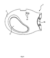
- the heat dissipation area 2a is set in an outer circumferential edge part of the flat surface part 2A which is of a generally elliptical shape formed by cutting a part of the egg-shaped form with a flat plane.
- the heat conduction member 9 of a generally flat elliptic annular shape having a predetermined width and a predetermined thickness is pasted generally along the heat dissipation area 2a.
- the heat conduction member 9 is of a generally elliptic annular shape having a discontinuous part only at one portion, however it may have a little deformed part or some discontinuous parts at multiple portions as far as its shape is formed generally along the elliptic annular shape.
- An opening portion 2A1 to expose a movable image receiving face 31a of the imaging device 31 and an opening portion 2A2 to expose an antenna 33a of the GPS receiver 33 are arranged on the flat surface part 2A.
- the casing 2 can be thermally connected to the windshield W that is difficult to be high in temperature even though receiving direct sunlight, the heat can be dissipated through the windshield W by making use of the windshield W as the heat dissipation member, thereby preventing the driving recorder 1 from malfunction due to the high temperature.
- the heat conduction member 9 is elastic and of the generally flat elliptic annular shape having the predetermined width and the predetermined thickness, the heat conduction member 9 suitably fits the curved windshield W so that it can be mounted on the windshield W securely. In addition, since the heat conduction member 9 fits like this, heat conduction is further improved.
- the casing 2 is made of the metal and the magnesium alloy, which is light, is used as the metal so that the casing 2 is weight saved as well as the heat dissipation efficiency is improved as much as possible, it is possible to mount the casing 2 on the windshield W more securely.
- the image receiving face 31a of the imaging device 31 and the antenna 33a of the GPS receiver 33 are arranged on the flat surface part 2A that faces the windshield W, nothing interrupts between the image receiving face 31a, the antenna 33a and the windshield W, it is possible to operate the driving recorder securely and smoothly.
- the angle of the image receiving face 31a of the imaging device 31 can be adjusted to a necessary angle, it is possible to attach the recording device to an arbitrary place of the windshield W without obstructing a driver's field of vision.
- a shape of the casing is not limited to the egg-shaped form, and the heat conduction member may be of a generally toric shape.
- a surface of the casing may be in black so as to prevent reflection, or may be mirror finished so as to make it difficult to absorb heat.
- the casing can be thermally connected to the windshield that is difficult to be high in temperature even though receiving the direct sunlight, the heat can be dissipated through the windshield by making use of the windshield as the heat dissipation member, thereby preventing the driving recorder from malfunction due to the high temperature.
Landscapes
- Engineering & Computer Science (AREA)
- Mechanical Engineering (AREA)
- Physics & Mathematics (AREA)
- General Physics & Mathematics (AREA)
- Chemical & Material Sciences (AREA)
- Combustion & Propulsion (AREA)
- Transportation (AREA)
- Time Recorders, Dirve Recorders, Access Control (AREA)
- Fittings On The Vehicle Exterior For Carrying Loads, And Devices For Holding Or Mounting Articles (AREA)
Description
- This invention relates to a driving recorder that records behavior or a surrounding situation of a vehicle during a certain period before and after a time of an accident or a hiyari-hatto (risk incident), in other words, a case when a driver feels chill because he or she is close to be involved in an accident even though this situation does not reach an accident in case an accident occurs or a driver feels chill because of the above reason, and that can preferably makes an after-the-fact analysis why the vehicle gets involved in the situation.
- Nowadays, car accidents have become a social problem and investigation for the accidents is absolutely imperative, for example, in order to avoid an accident by means of prior prediction or in order to enable an early settlement of a compensation problem of an accident. As a result of this, a vehicle-mounted driving recorder has been developed that can automatically record an image of outside or inside of a motor vehicle (an automobile) during driving and that can be utilized as an accident coping system such that it can be used as an evidence in case of an accident.
- Conventionally this kind of driving recorder comprises an imaging unit and a body to process and store its image, each of which is separately formed, however, recently this kind of driving recorder is downsized by integrally forming an imaging unit and a body due to downsizing of an image receiving element as shown in the
patent document 1. - This kind of driving recorder may be installed at any place as far as it can see a front of the vehicle, and the place may be any as far as the inside of the vehicle, for example, a roof part, a windshield and an upper surface of a dashboard.
- However, a conventional driving recorder does not deeply take into consideration that the inside of the vehicle is in a severe environment in respect of the temperature. Then the driving recorder wherein the imaging unit and the body are integrally formed might cause malfunction due to high temperature considering electric power consumption of the driving recorder itself in case the driving recorder is left in the vehicle with the window closed under the boiling sun during summer.
- Patent document 1: Japan patent laid open number
2004-345599 claim 1. - Then the present claimed invention focuses attention on that a window glass of a vehicle is difficult to be high in temperature under the boiling sun and intends to avoid a problem due to temperature raise by tightly attaching the casing to a window glass through a heat conduction member with making use of the window glass as a heat dissipation member.
- The objects underlying the present invention are achieved by a driving recorder according to
independent claim 1. Preferred embodiments of the driving recorder according to the present invention are within the scope of the respective dependent claims. - More specifically, the driving recorder in accordance with this invention is so arranged that one or multiple detection devices that sense a situation concerning a behavior, a surrounding conditions of a vehicle, or the like and that output situation data indicating the situation, and a situation data storage section that stores the situation data output from the detection device are held in a single casing, and is characterized by that a heat dissipation area is formed on the casing and a heat conduction member that has a predetermined thermal conductivity and whose one surface is connected to the heat dissipation area is arranged and another surface of the heat conduction member can be bonded to a window glass of the vehicle.
- In accordance with this arrangement, since the casing can be thermally connected to the window glass that is difficult to be high in temperature even though receiving the direct sunlight, the heat can be dissipated through the window glass by making use of the window glass as a heat dissipation member, thereby preventing the driving recorder from malfunction due to the high temperature.
- In order to dissipate the heat effectively, it is preferable that the heat dissipation area is made of metal.
- In order to prevent excessive temperature rise by further improving the heat dissipation effect and to make it possible to preferably attach the driving recorder to the window glass by weight saving, it is preferable that almost all of the casing is made of metal and the metal is a magnesium alloy.
- In order to make it possible to fittingly attach the driving recorder to a window glass even though the window glass is curved like an automobile windshield, it is preferable that the heat dissipation area is of a generally elliptical annular shape or a toric shape having a predetermined width, and the heat conduction member having a predetermined thickness and elasticity is arranged along the heat dissipation area. Furthermore, since the heat dissipation area and the heat conduction member are annular, it is possible to effectively utilize the space by arranging an image receiving face of the image receiving device in a center area surrounded by the annular heat dissipation area and the annular heat conduction member, thereby to further contribute to downsizing or weight saving of the whole driving recorder.
- As a concrete embodiment of the driving recorder in consideration of appearance, represented is that a whole shape of the driving recorder is of a generally egg-shaped form and an outer circumferential edge part of a generally elliptical flat surface part formed by cutting a part of the egg-shaped form with a flat surface is set as the heat dissipation area.
- In addition, as the detection device represented is that at least using an image receiving device, an acceleration sensor and a position sensor, and it is preferable that an image receiving surface of the image receiving device faces an opening of the generally elliptical flat surface part.
- In accordance with this invention, since the casing can be thermally connected to the windshield that is difficult to be high in temperature even though receiving the direct sunlight, the heat can be dissipated through a member of the windshield by making use of the windshield as the heat dissipation member, thereby preventing the driving recorder from malfunction due to the high temperature.
-
-
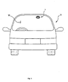
Fig. 1 is a pattern front view showing a case that a driving recorder in accordance with an embodiment of the invention is mounted on a vehicle. -
Fig. 2 is a perspective view of the driving recorder in accordance with this embodiment viewed from the inside of the vehicle. -
Fig. 3 is a perspective view of the driving recorder in accordance with this embodiment viewed from the outside of the vehicle. -
Fig. 4 is a front view of the driving recorder in accordance with this embodiment. -
Fig. 5 is a back view of the driving recorder in accordance with this embodiment. -
Fig. 6 is a side view of the driving recorder in accordance with this embodiment. -
Fig. 7 is a functional block diagram of the driving recorder in accordance with this embodiment. - 1... driving recorder, 2... casing, 2a... heat dissipation area, 3... detection device, 82, 7... situation data storage section (internal memory, detachable memory card), 9... heat conduction member
- An embodiment of the present claimed invention will be described with reference to
Fig. 1 through Fig. 7 . - A
driving recorder 1 in accordance with this embodiment is of a vehicle-mounted type as shown inFig. 1 or the like, to record behavior or a surrounding situation of a vehicle V during a certain period before and after a time of an accident or a hiyari-hatto (risk incident), in other words, a time when a driver feels chill because he or she is close to be involved in an accident, and basic configuration elements, more specifically, adetection device 3, an information processing device 8, an alert device 4, aninput device 5, a communication device 6 and adetachable recording device 7 are accommodated in asingle casing 2 whose overall shape is of a generally egg-shaped form so as to be an integral unit. - The
detection device 3, as shown inFig. 7 , senses a situation regarding the behavior or the surrounding situation of the vehicle and outputs situation data indicating its situation. In this embodiment thedetection device 3 comprises at least animaging device 31, anacceleration sensor 32 and aposition sensor 33. Theimaging device 31 takes an image of a situation of outside the vehicle and outputs situation data indicating the image (the moving image data), and may be, for example, a CCD camera. Theacceleration sensor 32 is of an arrangement that makes use of, for example, a Piezoresistance effect, and senses acceleration of one dimension to three dimensions (back and front, right and left, up and down, for example, in case of three dimensions) that applies to the vehicle and outputs the situation data (the acceleration data) indicating its acceleration. Theposition sensor 33 is, for example, a GPS receiver that catches electromagnetic waves from multiple satellites, senses a position of the vehicle V on which thedriving recorder 1 is mounted and outputs the situation data (position data) indicating its position. The situation data comprises vehicle speed data transmitted from a vehicle speed sensor (not shown in drawings) of the vehicle V and door open/close data indicating an opening or closing of a door, and the data is received through a connector CN. The connector CN is also used for an electric power supply. - The alert device 4 comprises
LEDs 41 as being an illuminant exposed to a surface of thecasing 2 and a sound output body (not shown in drawings) such as a buzzer or a speaker built-in thecasing 2. - The
input device 5 is a button switch exposed to the surface of thecasing 2. - The communication device 6 is hardware for wireless LAN that is built-in the
casing 2 and that sends and receives electromagnetic waves to and from a base station. - In this embodiment, the
detachable recording device 7 is a CF memory card that is mounted on aslot 2b opening toward a lateral side of thecasing 2 with allowing demounting. - The information processing device 8 is, as shown in
Fig. 4 , structurally a so-called computer circuit that is built-in thecasing 2 and that has aCPU 81, an internal memory 82 (for example, a nonvolatile memory) and an I/O buffer circuit 83 (there might be a case that an AD converter is included). Each device is controlled or information processed by operating theCPU 81 in accordance with programs stored in a predetermined area of theinternal memory 82. - With briefly explained, the
CPU 81 updates and temporarily stores the various situation data during driving, more specifically, the acceleration data, the position data and moving image data in a temporary area (hereinafter also called as a temporary data storage section) set in thememory 82 one after the other, and in case that an event indirectly indicating an occurrence of an accident, a hiyari-hatto (risk incident) or an abnormality occurs, theCPU 81 transfers and records the situation data during a certain period before and after the event in a regular area (hereinafter also called as a regular record data storage section) in thememory 82. - The event corresponds to a case wherein the acceleration (deceleration) indicated by the acceleration data exceeds a predetermined criterion value, a case wherein the period of the acceleration continues over a certain period, a case wherein the door is open or closed or a case wherein an electric power supply from a vehicle is halted. In this embodiment, depending on the event, only a case when some of the conditions occurs in combination such that the vehicle speed exceeds the upper limit, the acceleration or deceleration degree exceeds the predetermined criterion value or there is no brake, the data is recorded with making use of the case as a trigger so as to avoid recording useless data as much as possible.
- In addition, a learning function is also provided in order to prevent recording useless data. More specifically, prior to recording the data, the driving recorder inevitably reports to the driver whether or not the event is a hiyari-hatto (risk incident) or an accident by means of the alert device 4 and receives an input showing a judgment whether right or wrong (for example, ON/OFF of the button switch 5) from the driver. With repeating this operation, a driving preference of a driver can be grasped to some extent, and the event specific to the driver and indirectly indicating the accident or the like is learned by changing, for example, a predetermined acceleration criterion value.
- Furthermore, the recorded situation data is weighted based on a situation when the situation data is recorded and then classified in accordance with a level of the importance to be recorded. In case that the capacity of the memory runs out, it is so arranged that the situation data whose importance is lower than the importance of new situation data is automatically erased and the new situation data is recorded instead.
- The situation data recorded officially is transmitted to an analysis center (not shown in drawings) wirelessly, or transferred to a
detachable recording device 7 and thedetachable recording device 7 is demounted and then carried in the analysis center so as to be used for after-the-fact analysis. - In this embodiment, as shown in
Fig. 1 through Fig. 6 , it is so arranged that thecasing 2 is attached on a windshield W of the vehicle V with keeping a thermally connected state. - More specifically, almost all of the
casing 2 is made of metal (a magnesium alloy) and aheat dissipation area 2a is arranged in a part of thecasing 2. One surface of aheat conduction member 9 having adhesion properties and elasticity is pasted in theheat dissipation area 2a and thedriving recorder 1 is attached to an arbitrary place of the windshield W through theheat conduction member 9. - The
heat dissipation area 2a is set in an outer circumferential edge part of theflat surface part 2A which is of a generally elliptical shape formed by cutting a part of the egg-shaped form with a flat plane. Theheat conduction member 9 of a generally flat elliptic annular shape having a predetermined width and a predetermined thickness is pasted generally along theheat dissipation area 2a. In this embodiment, theheat conduction member 9 is of a generally elliptic annular shape having a discontinuous part only at one portion, however it may have a little deformed part or some discontinuous parts at multiple portions as far as its shape is formed generally along the elliptic annular shape. - An opening portion 2A1 to expose a movable
image receiving face 31a of theimaging device 31 and an opening portion 2A2 to expose an antenna 33a of theGPS receiver 33 are arranged on theflat surface part 2A. - In accordance with this embodiment, since the
casing 2 can be thermally connected to the windshield W that is difficult to be high in temperature even though receiving direct sunlight, the heat can be dissipated through the windshield W by making use of the windshield W as the heat dissipation member, thereby preventing the drivingrecorder 1 from malfunction due to the high temperature. - In addition, since the automobile V vibrates, a problem is prone to happen that the driving recorder is detached from the automobile V in a mounted state that the driving recorder is pasted. However, in this embodiment the
heat conduction member 9 is elastic and of the generally flat elliptic annular shape having the predetermined width and the predetermined thickness, theheat conduction member 9 suitably fits the curved windshield W so that it can be mounted on the windshield W securely. In addition, since theheat conduction member 9 fits like this, heat conduction is further improved. - Furthermore, since almost all of the
casing 2 is made of the metal and the magnesium alloy, which is light, is used as the metal so that thecasing 2 is weight saved as well as the heat dissipation efficiency is improved as much as possible, it is possible to mount thecasing 2 on the windshield W more securely. - In addition, since the
image receiving face 31a of theimaging device 31 and the antenna 33a of theGPS receiver 33 are arranged on theflat surface part 2A that faces the windshield W, nothing interrupts between theimage receiving face 31a, the antenna 33a and the windshield W, it is possible to operate the driving recorder securely and smoothly. In addition, since the angle of theimage receiving face 31a of theimaging device 31 can be adjusted to a necessary angle, it is possible to attach the recording device to an arbitrary place of the windshield W without obstructing a driver's field of vision. - The present claimed invention is not limited to the above-mentioned embodiment. For example, a shape of the casing is not limited to the egg-shaped form, and the heat conduction member may be of a generally toric shape. In addition, a surface of the casing may be in black so as to prevent reflection, or may be mirror finished so as to make it difficult to absorb heat.
- In accordance with this invention, since the casing can be thermally connected to the windshield that is difficult to be high in temperature even though receiving the direct sunlight, the heat can be dissipated through the windshield by making use of the windshield as the heat dissipation member, thereby preventing the driving recorder from malfunction due to the high temperature.
Claims (6)
- A driving recorder (1),
comprising one or multiple detection devices (3) that sense a situation concerning a behavior or surrounding conditions of a vehicle (V) and that output situation data indicating the situation, and a situation data storage section that stores the situation data output from the detection device (3), which is held in a casing (2),
characterized by
a heat dissipation area (2a) formed on the casing (2),
a heat conduction member (9) having a predetermined thermal conductivity and having one surface connected to the heat dissipation area (2a) and,
another surface of the heat conduction member (9) to be bonded to a window glass (W) of the vehicle (V). - The driving recorder (1) described in claim 1,
wherein the heat dissipation area (2a) is made of metal. - The driving recorder (1) described in claim 1 or 2,
wherein almost all of the casing (2) is made of metal and the metal is magnesium alloy. - The driving recorder (1) described in claim 1,
wherein the heat dissipation area (2a) is of a generally elliptical annular shape or a toric shape having a predetermined width, and the heat conduction member (9) having a predetermined thickness and elasticity is arranged along the heat dissipation area (2a). - The driving recorder (1) described in claim 4,
wherein a whole shape of the driving recorder (1) is of a generally egg-shaped form, and an outer circumferential edge, part of a generally elliptical flat surface part (2A) formed by cutting a part of the egg-shaped form with a flat plane, is set as the heat dissipation area (2a). - The driving recorder (1) described in claim 5,
wherein the detection device (3) comprises at least an image receiving device (31), an acceleration sensor (32) and a position sensor (33), and an image receiving surface (31a) of the image receiving device (31) faces an opening (2A1) of the generally elliptical flat surface part (2A).
Applications Claiming Priority (2)
| Application Number | Priority Date | Filing Date | Title |
|---|---|---|---|
| JP2005213409 | 2005-06-25 | ||
| PCT/JP2006/312585 WO2007000941A1 (en) | 2005-06-25 | 2006-06-23 | Driving recorder |
Publications (3)
| Publication Number | Publication Date |
|---|---|
| EP1908671A1 EP1908671A1 (en) | 2008-04-09 |
| EP1908671A4 EP1908671A4 (en) | 2009-11-04 |
| EP1908671B1 true EP1908671B1 (en) | 2010-08-18 |
Family
ID=37595193
Family Applications (1)
| Application Number | Title | Priority Date | Filing Date |
|---|---|---|---|
| EP06767235A Not-in-force EP1908671B1 (en) | 2005-06-25 | 2006-06-23 | Driving recorder |
Country Status (7)
| Country | Link |
|---|---|
| US (1) | US8280577B2 (en) |
| EP (1) | EP1908671B1 (en) |
| JP (1) | JP5005535B2 (en) |
| KR (1) | KR20080022096A (en) |
| CN (1) | CN101208238B (en) |
| DE (1) | DE602006016290D1 (en) |
| WO (1) | WO2007000941A1 (en) |
Families Citing this family (8)
| Publication number | Priority date | Publication date | Assignee | Title |
|---|---|---|---|---|
| JP4859756B2 (en) * | 2007-05-31 | 2012-01-25 | 富士通テン株式会社 | Image recording condition setting method in drive recorder |
| CN103723096B (en) * | 2014-01-10 | 2015-10-21 | 上海大众汽车有限公司 | With the drive assist system of radio communication function |
| JP6897750B2 (en) * | 2014-07-01 | 2021-07-07 | 株式会社リコー | Imaging unit |
| JP2016014564A (en) * | 2014-07-01 | 2016-01-28 | 株式会社リコー | Imaging unit |
| JP6303974B2 (en) | 2014-10-22 | 2018-04-04 | 株式会社デンソー | In-vehicle camera device and in-vehicle system |
| TWM563372U (en) * | 2018-02-01 | 2018-07-11 | 雄鉅實業有限公司 | Electronic device with L-shaped fastening device |
| CN112242012A (en) * | 2019-07-18 | 2021-01-19 | 上汽通用汽车有限公司 | Event recording device and method based on vehicle camera |
| JP7624693B2 (en) * | 2020-03-31 | 2025-01-31 | 株式会社ユピテル | In-vehicle equipment, electronic devices and mounting parts, etc. |
Family Cites Families (54)
| Publication number | Priority date | Publication date | Assignee | Title |
|---|---|---|---|---|
| JPS6029753A (en) | 1983-07-28 | 1985-02-15 | Mita Ind Co Ltd | Method for filtering liquid dispersion of organic photosensitive material |
| JPS6029753U (en) * | 1983-08-05 | 1985-02-28 | トヨタ自動車株式会社 | automotive window glass |
| JPH0139245Y2 (en) * | 1985-07-15 | 1989-11-24 | ||
| JPS63265383A (en) | 1987-04-22 | 1988-11-01 | 株式会社 南部電機製作所 | Recorder for operation status of vehicles |
| JP2607889B2 (en) | 1987-08-04 | 1997-05-07 | 光洋精工株式会社 | Reduction motor |
| GB8825446D0 (en) * | 1988-10-31 | 1988-11-30 | Lawrence M J | Vehicle security camera |
| JPH05197858A (en) | 1992-01-21 | 1993-08-06 | Matsushita Electric Ind Co Ltd | Driving recorder |
| JPH0644430A (en) | 1992-07-23 | 1994-02-18 | Nissan Diesel Motor Co Ltd | Traveling recorder for vehicle |
| JPH08169284A (en) | 1994-12-20 | 1996-07-02 | Matsushita Electric Ind Co Ltd | In-vehicle control unit structure |
| JPH0950547A (en) | 1995-08-10 | 1997-02-18 | Fujitsu Ten Ltd | Operation recording device |
| JPH09231422A (en) | 1996-02-22 | 1997-09-05 | Fujitsu Ltd | Vehicle operation record data recording device and vehicle operation management device |
| JPH09288573A (en) | 1996-04-23 | 1997-11-04 | Mitsubishi Electric Corp | In-vehicle control device |
| US5948026A (en) | 1996-10-24 | 1999-09-07 | General Motors Corporation | Automotive data recorder |
| JP3166634B2 (en) | 1996-11-07 | 2001-05-14 | 日産自動車株式会社 | Fault storage device for vehicle control unit |
| JPH11107846A (en) | 1997-10-07 | 1999-04-20 | Jatco Corp | Vehicle control device |
| US6163338A (en) | 1997-12-11 | 2000-12-19 | Johnson; Dan | Apparatus and method for recapture of realtime events |
| JP3549148B2 (en) | 1997-12-19 | 2004-08-04 | 矢崎総業株式会社 | Vehicle operation information collection device |
| JP2000043764A (en) | 1998-07-27 | 2000-02-15 | Nec Mobile Commun Ltd | Traveling state recorder for vehicle and vehicle state monitor |
| JP3044025B1 (en) | 1998-12-09 | 2000-05-22 | 株式会社データ・テック | Operation management system capable of analyzing driving tendency and its constituent devices |
| JP2000092420A (en) | 1998-09-16 | 2000-03-31 | Toshiba Corp | Image information recording device |
| US6088635A (en) | 1998-09-28 | 2000-07-11 | Roadtrac, Llc | Railroad vehicle accident video recorder |
| US6141611A (en) | 1998-12-01 | 2000-10-31 | John J. Mackey | Mobile vehicle accident data system |
| JP2000194895A (en) | 1998-12-25 | 2000-07-14 | Tmp:Kk | Vehicle operation management system and digital vehicle operation recording device |
| JP2000309287A (en) | 1999-02-25 | 2000-11-07 | Nhk Engineering Services Inc | Image data recording apparatus and image data recording method |
| US6266588B1 (en) | 1999-03-01 | 2001-07-24 | Mcclellan Scott B. | Vehicle motion detection and recording method and apparatus |
| US6185490B1 (en) | 1999-03-15 | 2001-02-06 | Thomas W. Ferguson | Vehicle crash data recorder |
| JP3509631B2 (en) | 1999-05-28 | 2004-03-22 | トヨタ自動車株式会社 | Vehicle data recording device |
| JP4394780B2 (en) | 1999-10-08 | 2010-01-06 | クラリオン株式会社 | Mobile body information recording device |
| JP3555106B2 (en) | 1999-10-26 | 2004-08-18 | 矢崎総業株式会社 | Safe driving support device |
| US6246933B1 (en) | 1999-11-04 | 2001-06-12 | BAGUé ADOLFO VAEZA | Traffic accident data recorder and traffic accident reproduction system and method |
| JP2002042288A (en) | 2000-07-26 | 2002-02-08 | Yazaki Corp | Operation status recording device and operation management system using the same |
| US6356824B1 (en) | 2001-01-23 | 2002-03-12 | Meritor Heavy Vehicle Technology, Llc | Vehicle systems data storage |
| FR2823048B1 (en) | 2001-03-30 | 2003-07-04 | Claude Bendavid | DEVICE FOR STORING A VISUAL SEQUENCE FOLLOWING THE SENDING OF AN ALARM SIGNAL ON BOARD A VEHICLE |
| JP3838055B2 (en) | 2001-05-24 | 2006-10-25 | 株式会社デンソー | In-vehicle control device |
| JP3549505B2 (en) | 2001-08-10 | 2004-08-04 | 本田技研工業株式会社 | Data recording device |
| JP2003069936A (en) | 2001-08-27 | 2003-03-07 | Nippon Signal Co Ltd:The | Vehicle use drive recorder |
| JP2003168882A (en) * | 2001-11-30 | 2003-06-13 | Sony Corp | Thermal conductive sheet |
| US7386376B2 (en) | 2002-01-25 | 2008-06-10 | Intelligent Mechatronic Systems, Inc. | Vehicle visual and non-visual data recording system |
| JP3852347B2 (en) | 2002-03-04 | 2006-11-29 | 日産自動車株式会社 | Vehicle information recording method and apparatus |
| US20030222981A1 (en) | 2002-06-04 | 2003-12-04 | Kisak Jeffrey James | Locomotive wireless video recorder and recording system |
| JP2004064634A (en) | 2002-07-31 | 2004-02-26 | Seiko Epson Corp | Operation information recording device |
| JP2004075033A (en) * | 2002-08-17 | 2004-03-11 | Hisao Saito | On-vehicle device for automatically video image picking up and recording car accident, and recording method therefor |
| JP3969278B2 (en) | 2002-10-21 | 2007-09-05 | 株式会社デンソー | Electronic control unit |
| JP4116896B2 (en) | 2003-02-07 | 2008-07-09 | 株式会社堀場製作所 | Vehicle operation management system |
| JP2004345599A (en) | 2003-05-26 | 2004-12-09 | Mitsumi Electric Co Ltd | In-vehicle driving recorder |
| US20040267419A1 (en) * | 2003-06-25 | 2004-12-30 | Jeng Jack Ing | Electronic circuit system named mobile safety communication (MSC) device embedded in the rearview/side mirror of a vehicle |
| DE10339647A1 (en) | 2003-08-28 | 2005-03-24 | Robert Bosch Gmbh | Device for driver warning |
| US7389178B2 (en) | 2003-12-11 | 2008-06-17 | Greenroad Driving Technologies Ltd. | System and method for vehicle driver behavior analysis and evaluation |
| JP4347760B2 (en) | 2004-07-07 | 2009-10-21 | 株式会社データ・テック | Mobile operation management method, system and component device thereof |
| US20060184295A1 (en) | 2005-02-17 | 2006-08-17 | Steve Hawkins | On-board datalogger apparatus and service methods for use with vehicles |
| CN101176121B (en) | 2005-07-01 | 2012-12-19 | 财团法人日本汽车研究所 | Driving recorder |
| CN100341777C (en) | 2006-04-11 | 2007-10-10 | 太原理工大学 | Method of preparing carbon pellets by using heavy oil residue as raw material |
| US7957863B2 (en) | 2006-11-10 | 2011-06-07 | Fujitsu Ten Limited | Vehicle information recording apparatus, program, and recording medium |
| KR101089134B1 (en) | 2009-09-14 | 2011-12-05 | 엠텍비젼 주식회사 | Vehicle image storage device and driving information providing method |
-
2006
- 2006-06-23 WO PCT/JP2006/312585 patent/WO2007000941A1/en not_active Ceased
- 2006-06-23 KR KR1020077028712A patent/KR20080022096A/en not_active Withdrawn
- 2006-06-23 CN CN200680022883XA patent/CN101208238B/en not_active Expired - Fee Related
- 2006-06-23 US US11/993,834 patent/US8280577B2/en not_active Expired - Fee Related
- 2006-06-23 JP JP2007523428A patent/JP5005535B2/en not_active Expired - Fee Related
- 2006-06-23 DE DE602006016290T patent/DE602006016290D1/en active Active
- 2006-06-23 EP EP06767235A patent/EP1908671B1/en not_active Not-in-force
Also Published As
| Publication number | Publication date |
|---|---|
| JPWO2007000941A1 (en) | 2009-01-22 |
| EP1908671A4 (en) | 2009-11-04 |
| DE602006016290D1 (en) | 2010-09-30 |
| EP1908671A1 (en) | 2008-04-09 |
| HK1113117A1 (en) | 2008-09-26 |
| KR20080022096A (en) | 2008-03-10 |
| US20100152964A1 (en) | 2010-06-17 |
| WO2007000941A1 (en) | 2007-01-04 |
| US8280577B2 (en) | 2012-10-02 |
| CN101208238B (en) | 2011-12-14 |
| JP5005535B2 (en) | 2012-08-22 |
| CN101208238A (en) | 2008-06-25 |
Similar Documents
| Publication | Publication Date | Title |
|---|---|---|
| US8040376B2 (en) | Vehicle monitor apparatus | |
| ES2931178T3 (en) | Method and system for recording vehicle behavior | |
| KR100909368B1 (en) | Vehicle rear surveillance camera installation structure | |
| EP1883855A4 (en) | VEHICLE MIRROR ASSEMBLY HAVING REFLECTIVE ELEMENT INFORMATION | |
| EP1908671B1 (en) | Driving recorder | |
| JP4271149B2 (en) | Exterior rearview mirror assembly for a vehicle designed to support an image detection device | |
| KR20190027559A (en) | Vehicle And Control Method Thereof | |
| WO2007042798A2 (en) | Improvements in or relating to vehicles | |
| JP2004075033A (en) | On-vehicle device for automatically video image picking up and recording car accident, and recording method therefor | |
| EP3444785B1 (en) | Method and system for detecting an incident, accident and/or scam of a vehicle | |
| JP2013258572A (en) | Holder for portable information terminal | |
| HK1113117B (en) | Driving recorder | |
| CN222167303U (en) | Vehicle-mounted lens and vehicle | |
| CN210062863U (en) | Vehicle-mounted recorder | |
| CN212515927U (en) | Vehicle event data recorder with heat radiation structure | |
| JP2004345599A (en) | In-vehicle driving recorder | |
| CN212724087U (en) | Vehicle event data recorder with remind function | |
| JP2020037342A (en) | On-vehicle camera device | |
| JP5048237B2 (en) | Driving information recording device | |
| CN208881721U (en) | Vehicle-mounted ADAS device | |
| CN220651318U (en) | Early warning type automobile data recorder | |
| KR100896052B1 (en) | Camera assembly replaceable camera module | |
| CN221551248U (en) | Vehicle event data recorder and on-vehicle system | |
| KR20130062847A (en) | Auto image conversion side camera using geomagnetic sensor | |
| CN220569204U (en) | Electronic device for vehicle |
Legal Events
| Date | Code | Title | Description |
|---|---|---|---|
| PUAI | Public reference made under article 153(3) epc to a published international application that has entered the european phase |
Free format text: ORIGINAL CODE: 0009012 |
|
| 17P | Request for examination filed |
Effective date: 20080118 |
|
| AK | Designated contracting states |
Kind code of ref document: A1 Designated state(s): DE FR GB IT |
|
| RBV | Designated contracting states (corrected) |
Designated state(s): DE FR GB IT |
|
| REG | Reference to a national code |
Ref country code: HK Ref legal event code: DE Ref document number: 1113117 Country of ref document: HK |
|
| DAX | Request for extension of the european patent (deleted) | ||
| A4 | Supplementary search report drawn up and despatched |
Effective date: 20091001 |
|
| GRAP | Despatch of communication of intention to grant a patent |
Free format text: ORIGINAL CODE: EPIDOSNIGR1 |
|
| RIC1 | Information provided on ipc code assigned before grant |
Ipc: G07C 5/08 20060101AFI20100215BHEP |
|
| GRAS | Grant fee paid |
Free format text: ORIGINAL CODE: EPIDOSNIGR3 |
|
| GRAA | (expected) grant |
Free format text: ORIGINAL CODE: 0009210 |
|
| AK | Designated contracting states |
Kind code of ref document: B1 Designated state(s): DE FR GB IT |
|
| REG | Reference to a national code |
Ref country code: GB Ref legal event code: FG4D |
|
| REF | Corresponds to: |
Ref document number: 602006016290 Country of ref document: DE Date of ref document: 20100930 Kind code of ref document: P |
|
| REG | Reference to a national code |
Ref country code: HK Ref legal event code: GR Ref document number: 1113117 Country of ref document: HK |
|
| PLBE | No opposition filed within time limit |
Free format text: ORIGINAL CODE: 0009261 |
|
| STAA | Information on the status of an ep patent application or granted ep patent |
Free format text: STATUS: NO OPPOSITION FILED WITHIN TIME LIMIT |
|
| 26N | No opposition filed |
Effective date: 20110519 |
|
| PGFP | Annual fee paid to national office [announced via postgrant information from national office to epo] |
Ref country code: FR Payment date: 20110621 Year of fee payment: 6 |
|
| PGFP | Annual fee paid to national office [announced via postgrant information from national office to epo] |
Ref country code: GB Payment date: 20110621 Year of fee payment: 6 |
|
| REG | Reference to a national code |
Ref country code: DE Ref legal event code: R097 Ref document number: 602006016290 Country of ref document: DE Effective date: 20110519 |
|
| PGFP | Annual fee paid to national office [announced via postgrant information from national office to epo] |
Ref country code: IT Payment date: 20110613 Year of fee payment: 6 |
|
| PGFP | Annual fee paid to national office [announced via postgrant information from national office to epo] |
Ref country code: DE Payment date: 20110615 Year of fee payment: 6 |
|
| GBPC | Gb: european patent ceased through non-payment of renewal fee |
Effective date: 20120623 |
|
| PG25 | Lapsed in a contracting state [announced via postgrant information from national office to epo] |
Ref country code: IT Free format text: LAPSE BECAUSE OF NON-PAYMENT OF DUE FEES Effective date: 20120623 |
|
| REG | Reference to a national code |
Ref country code: FR Ref legal event code: ST Effective date: 20130228 |
|
| REG | Reference to a national code |
Ref country code: DE Ref legal event code: R119 Ref document number: 602006016290 Country of ref document: DE Effective date: 20130101 |
|
| PG25 | Lapsed in a contracting state [announced via postgrant information from national office to epo] |
Ref country code: GB Free format text: LAPSE BECAUSE OF NON-PAYMENT OF DUE FEES Effective date: 20120623 Ref country code: FR Free format text: LAPSE BECAUSE OF NON-PAYMENT OF DUE FEES Effective date: 20120702 Ref country code: DE Free format text: LAPSE BECAUSE OF NON-PAYMENT OF DUE FEES Effective date: 20130101 |