EP1908619B1 - Unité de retenue pour l'installation d'un cylindre de gaz combustible dans un véhicule à moteur - Google Patents
Unité de retenue pour l'installation d'un cylindre de gaz combustible dans un véhicule à moteur Download PDFInfo
- Publication number
- EP1908619B1 EP1908619B1 EP07118000A EP07118000A EP1908619B1 EP 1908619 B1 EP1908619 B1 EP 1908619B1 EP 07118000 A EP07118000 A EP 07118000A EP 07118000 A EP07118000 A EP 07118000A EP 1908619 B1 EP1908619 B1 EP 1908619B1
- Authority
- EP
- European Patent Office
- Prior art keywords
- cylinder
- motor vehicle
- portions
- belt
- seat
- Prior art date
- Legal status (The legal status is an assumption and is not a legal conclusion. Google has not performed a legal analysis and makes no representation as to the accuracy of the status listed.)
- Active
Links
Images


Classifications
-
- B—PERFORMING OPERATIONS; TRANSPORTING
- B60—VEHICLES IN GENERAL
- B60K—ARRANGEMENT OR MOUNTING OF PROPULSION UNITS OR OF TRANSMISSIONS IN VEHICLES; ARRANGEMENT OR MOUNTING OF PLURAL DIVERSE PRIME-MOVERS IN VEHICLES; AUXILIARY DRIVES FOR VEHICLES; INSTRUMENTATION OR DASHBOARDS FOR VEHICLES; ARRANGEMENTS IN CONNECTION WITH COOLING, AIR INTAKE, GAS EXHAUST OR FUEL SUPPLY OF PROPULSION UNITS IN VEHICLES
- B60K15/00—Arrangement in connection with fuel supply of combustion engines or other fuel consuming energy converters, e.g. fuel cells; Mounting or construction of fuel tanks
- B60K15/03—Fuel tanks
- B60K15/063—Arrangement of tanks
- B60K15/067—Mounting of tanks
- B60K15/07—Mounting of tanks of gas tanks
Definitions
- the present invention relates to a restraining unit for fitting a combustible gas cylinder into a motor vehicle.
- methane gas can be stored in highpressure metal containers or cylinders. Because of high storage pressure values, the shape of said containers is necessarily substantially cylindrical.
- the cylinders are fitted onto the motor vehicles through the use of an added support frame, fixed to a bearing structure of the motor vehicle and having a saddle which accommodates about half the circumference of the cylinder.
- a pair of metal belts wind round the other half of the circumference and are fixed at their ends to the support frame, by means of screws for example.
- the cylinders may be housed both inside and outside the motor vehicles.
- the cylinders are installed in the luggage boot, to the detriment of the capacity of the boot itself.
- the cylinders are fitted underneath the platform: the belts support the weight of the cylinder, while the support frame supports the loads in correspondence with the fixing points of the belts themselves and transfers said loads to the bearing structure of the motor vehicle.
- the weight of the support frame is also to be understood as additional relative to the standard version, and is relatively substantial. Furthermore, the space requirement of the support frame is not insignificant and may be incompatible with the specified limitations of the layout of the surrounding components.
- the purpose of the present invention is to implement a restraining unit so as to fit a combustible gas cylinder into a motor vehicle, which allows the problems disclosed above to be resolved simply and cost-effectively.
- a restraining unit is implemented so as to fit a combustible gas cylinder into a motor vehicle; the unit comprising:
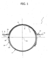
- 1 is used to indicate a restraining unit for fitting a combustible gas cylinder 2 into a motor vehicle, in particular a methane gas cylinder stored at highpressure, having a substantially cylindrical shape with two end segments.
- the unit 1 comprises a support structure 3, which is defined by a floor portion of the motor vehicle (not shown) and is able to be fitted in a fixed position, in a way not shown, in the motor vehicle.
- the structure 3 comprises an intermediate wall 4, the lower surface of which defines a seat or cavity 5 complimentary to the external profile of an upper portion 6 of the cylinder 2, which is laid directly on the wall 4.
- the structure 3 further comprises a substantially plane perimeter wall 7 ( figure 3 ), arranged around the wall 4, implemented in a single piece with the wall 4, and comprising in its turn two lateral portions 8, which are arranged on opposite sides of the seat 5 and have respective slotted holes 9.
- the portions 8 carry, for each hole 9, a respective connection element 11.
- the elements 11 are defined by pins which are fixed to the portions 8, preferably by welding, protrude upwards from the upper surface of the portions 8 and are each arranged in a position adjacent to the relevant slotted hole 9, on the opposite side relative to the wall 4.
- the unit 1 comprises, furthermore, two restraining belts 16, each of which is constituted by two metal strips 17a, 17b coupled together by means of a hinge 18 not described in detail, so as to be able to rotate one relative to the other around a direction parallel to a longitudinal axis 19 of the cylinder 2 and of the seat 5.
- Each belt 16 carries a respective pair of reinforcement elements 24, which are free to slide along the strip 17a.
- the elements 24 comprise respective plane bases 29, which are coupled to the portions 8 by means of the interposition of respective seals 32 and have respective slotted holes 30 aligned with the slotted holes 9.
- the strips 17a pass through the slotted holes 30 and 9 with play: the longitudinal edges of the slotted holes 9 are defined by ribs 31 which face each other and protrude downwards relative to the lower surface of the portions 8, so as to prevent sticking between said edges and the strips 17a.
- the bases 29 have respective holes 33 engaged by the elements 11 and comprise respective embossments 37 ( figure 2 ), in other words portions which are raised upwards relative to the remaining part of the bases 29 and to the plane defined by the portions 8 and are obtained by stamping the elements 24.
- a lateral portion of the seals 32 is compressed and restrained between the portions 37 and 8.
- the seals 32 are also provided with slotted holes, so as to fit the strip 17a, and have dimensions, positions and shape to guarantee the fluid seal around the strip 17a through the slotted holes 9.
- the elements 24 comprise respective support walls 35, connected to the bases 24, having at least in part a curved profile complimentary to that of the wall 4, and arranged or gripped between the wall 4 itself and the strips 17a.
- the strips 17a are accommodated in respective grooves, defined by the wall 4 and by a pair of ribs 38.
- the ribs 38 are extended in an arc, protrude from the upper surface of the wall 4, are fixed relative to the wall 4 and restrain the walls 35 of the elements 24 in a direction parallel to the axis 19.
- the motor vehicle is already pre-prepared with the structure 3 fitted so as to define the floor platform.
- the belts 16 are assembled, in other words the strips 17a, 17b are coupled to each other by means of the hinge 18 and the seals 32 and the elements 24 are fitted to the strip 17a ( figure 4 ).
- the free ends of the strips 17a, 17b (indicated by the reference numbers 27 in figure 4 ) are made to pass through the slotted holes 9, with care taken to insert the seals 32 appropriately into the slotted holes 9.
- the bases 29 of the elements 24 are brought closer to the seals 32, engaging the elements 11 in the holes 33.
- Fixing buttons or washers 34 are successively inserted at pressure onto the elements 11 so as to tighten the base 29 towards the portions 8, so as to force the seals 32 and to bind the elements 24 in the fixed position, pending closure of the belts 16 around the cylinder 2.
- the motor vehicle is first raised so as to give sufficient space underneath the platform or floor of the motor vehicle.
- the ends 27 are brought together making the strip 17b rotate around the hinge 18 and are fixed to each other, for example by means of a screw or pin device not described in detail, so as to close the belts 16 in a ring and to wind completely round the cylinder 2 by interposing the walls 4.
- the procedure for disassembling the cylinder 2 is constituted by the previous operations carried out in reverse order.
- this is a restraining unit in which the belts 16 discharge the weight of the cylinder 2 uniformly over the whole circumference arc of the wall 4.
- the coupling between the cylinder 2 and the structure 3 is substantially integral in nature in as much as the belt 16 is closed in a vice over the lower circumference arc of the cylinder 2, on one side, and over the wall 4 shaped as a saddle on the other side, making a single block. Because of this coupling there are no areas subject to stress concentration, typical conversely of the screw connections between belts and support structure.
- the belt 16 shaped in a ring allows the forces due to the weight of the cylinder 2 to be discharged over the whole strip 17a supported on the wall 4, uniformly distributing the loads and thereby eliminating the areas of stress concentration.
- the floor or platform of the motor vehicle is configured to accommodate a cylinder 2 of sufficient diameter to guarantee sufficient autonomy of the motor vehicle.
- the structure 3 takes up less space, is more functional, lighter and less costly, relative to known solutions which provide for an additional support frame.
- a reduction is also found in the time taken and in the costs as regards the process for assembling the unit 1 and fitting the cylinders 2 on the motor vehicle relative to known solutions provided with an additional support frame, due to the smaller number of components to be assembled and the small number of operations to be carried out.
- the structure 3 could be defined by a modular floor form.
Landscapes
- Engineering & Computer Science (AREA)
- Life Sciences & Earth Sciences (AREA)
- Sustainable Development (AREA)
- Sustainable Energy (AREA)
- Chemical & Material Sciences (AREA)
- Combustion & Propulsion (AREA)
- Transportation (AREA)
- Mechanical Engineering (AREA)
- Cooling, Air Intake And Gas Exhaust, And Fuel Tank Arrangements In Propulsion Units (AREA)
- Body Structure For Vehicles (AREA)
- Fluid-Damping Devices (AREA)
- Portable Nailing Machines And Staplers (AREA)
Claims (5)
- Unité de retenue (1) pour l'installation d'un cylindre de gaz combustible dans un véhicule à moteur, l'unité comprenant :- une structure support (3) définissant un siège (5) qui abrite, en utilisation, une partie supérieure (6) dudit cylindre (2) ;- des courroies (16) disposées, en utilisation, autour d'une partie inférieure dudit cylindre (2) et reliées à ladite structure support (3) ;caractérisée en ce que la structure support (3) est définie par une partie du plancher dudit véhicule à moteur et comprend une paroi intermédiaire (4) définissant ledit siège (5) et deux portions de parois latérales (8) disposées sur des côtés opposés dudit siège (5) et possédant des trous respectifs allongés (9) ;
et en ce que lesdites courroies comprennent au moins une courroie passant à travers les trous allongés (9) et définissant une boucle qui, en utilisation, entoure complètement ledit cylindre (2) avec l'interposition de ladite paroi intermédiaire (4). - Unité selon la revendication 1, caractérisée en ce qu'elle comprend deux pièces de renfort (24) portées par lesdites courroies et comprenant des premières portions respectives (35) reliées à ladite paroi intermédiaire (4) et des secondes portions respectives (29), chacune étant reliée à ladite portion de paroi latérale respective (8).
- Unité selon la revendication 1 ou 2, caractérisée en ce qu'elle comprend des moyens de fixation (32) pour garantir la fixation facile à travers desdits trous allongés (9) autour de ladite courroie (16).
- Unité selon les revendications 2 et 3, caractérisée en ce que ces moyens de fixation (32) comprennent deux joints soutenus par ladite courroie (16) et qui sont enfoncés entre lesdites portions des parois latérales (a) et lesdites secondes portions (29).
- Unité selon la revendication 2 ou 3, caractérisée en ce qu'elle comprend des éléments de liaison (11) fixés et faisant saillie par rapport auxdites portions de parois latérales (8), et que lesdites secondes portions (29) possèdent des trous respectifs (33) dans lesquels sont engagés lesdits éléments de liaison (11).
Applications Claiming Priority (1)
| Application Number | Priority Date | Filing Date | Title |
|---|---|---|---|
| IT000721A ITTO20060721A1 (it) | 2006-10-06 | 2006-10-06 | Gruppo di trattenimento per montare una bombola di gas combustibile in un autoveicolo |
Publications (2)
| Publication Number | Publication Date |
|---|---|
| EP1908619A1 EP1908619A1 (fr) | 2008-04-09 |
| EP1908619B1 true EP1908619B1 (fr) | 2009-12-09 |
Family
ID=38191367
Family Applications (1)
| Application Number | Title | Priority Date | Filing Date |
|---|---|---|---|
| EP07118000A Active EP1908619B1 (fr) | 2006-10-06 | 2007-10-05 | Unité de retenue pour l'installation d'un cylindre de gaz combustible dans un véhicule à moteur |
Country Status (5)
| Country | Link |
|---|---|
| EP (1) | EP1908619B1 (fr) |
| AT (1) | ATE451266T1 (fr) |
| DE (1) | DE602007003655D1 (fr) |
| ES (1) | ES2337199T3 (fr) |
| IT (1) | ITTO20060721A1 (fr) |
Cited By (1)
| Publication number | Priority date | Publication date | Assignee | Title |
|---|---|---|---|---|
| CN103074906A (zh) * | 2011-10-25 | 2013-05-01 | 合肥杰事杰新材料股份有限公司 | 一种沼气池防护垫的施工方法 |
Families Citing this family (2)
| Publication number | Priority date | Publication date | Assignee | Title |
|---|---|---|---|---|
| EP2497667B1 (fr) * | 2009-11-06 | 2016-12-14 | Honda Motor Co., Ltd. | Réservoir de gaz |
| US9193261B2 (en) | 2012-03-21 | 2015-11-24 | Agility Fuel Systems, Inc. | Strap guide and tank mounting fixture |
Family Cites Families (2)
| Publication number | Priority date | Publication date | Assignee | Title |
|---|---|---|---|---|
| DE9010169U1 (de) * | 1990-07-04 | 1990-12-20 | ZÜ-RE-WI Siegfried Zühlke, 4840 Rheda-Wiedenbrück | Halterung für Gastank |
| US6698212B2 (en) * | 2001-07-03 | 2004-03-02 | Thermo King Corporation | Cryogenic temperature control apparatus and method |
-
2006
- 2006-10-06 IT IT000721A patent/ITTO20060721A1/it unknown
-
2007
- 2007-10-05 DE DE602007003655T patent/DE602007003655D1/de active Active
- 2007-10-05 ES ES07118000T patent/ES2337199T3/es active Active
- 2007-10-05 EP EP07118000A patent/EP1908619B1/fr active Active
- 2007-10-05 AT AT07118000T patent/ATE451266T1/de not_active IP Right Cessation
Cited By (2)
| Publication number | Priority date | Publication date | Assignee | Title |
|---|---|---|---|---|
| CN103074906A (zh) * | 2011-10-25 | 2013-05-01 | 合肥杰事杰新材料股份有限公司 | 一种沼气池防护垫的施工方法 |
| CN103074906B (zh) * | 2011-10-25 | 2015-05-20 | 合肥杰事杰新材料股份有限公司 | 一种沼气池防护垫的施工方法 |
Also Published As
| Publication number | Publication date |
|---|---|
| ES2337199T3 (es) | 2010-04-21 |
| EP1908619A1 (fr) | 2008-04-09 |
| DE602007003655D1 (de) | 2010-01-21 |
| ITTO20060721A1 (it) | 2008-04-07 |
| ATE451266T1 (de) | 2009-12-15 |
Similar Documents
| Publication | Publication Date | Title |
|---|---|---|
| KR101876989B1 (ko) | 자동차용 현수 장치 | |
| CA2254192C (fr) | Reservoir de carburant modulaire, ensemble de montage sur vehicule et methode d'installation | |
| EP1908619B1 (fr) | Unité de retenue pour l'installation d'un cylindre de gaz combustible dans un véhicule à moteur | |
| US20020069840A1 (en) | Double walled fuel tank with integral generator set mounting frame | |
| CN103375681A (zh) | 蓄压器装置 | |
| CA2557118A1 (fr) | Reservoir a combustible gazeux embarque | |
| US20250229618A1 (en) | Bracket assembly for attaching component to vehicle | |
| JP2007500640A (ja) | 商用車用支持フレーム | |
| US20130306644A1 (en) | Multi-Piece Vehicle Tank Enclosure | |
| KR19980087022A (ko) | 수동 체인 블록 | |
| JP7072407B2 (ja) | 移動式クレーン用車両フレームおよび移動式クレーン | |
| CA2455535A1 (fr) | Support d'echelle | |
| KR101793363B1 (ko) | 주차 유도 전광판 | |
| CN108408276B (zh) | 一种阀门箱、罐式集装箱以及箱门安装结构 | |
| CN112018653A (zh) | 气体绝缘的容器 | |
| JP5603820B2 (ja) | アンカーボックス | |
| KR200298713Y1 (ko) | 스톱퍼 기능을 갖춘 배전반 도어 경첩 | |
| CN210462254U (zh) | 链式型材连接支架 | |
| ES2242506A1 (es) | Estructura de montaje de cubierta de carroceria de vehiculo y bloqueo de asiento para un vehiculo tipo scooter. | |
| CN211869591U (zh) | 电池壳体装配结构和带有电池壳体装配结构的电动车 | |
| CN220054549U (zh) | 一种榫卯卡扣式可重复利用包装箱 | |
| KR100393371B1 (ko) | 휠 스케일 | |
| CN221989437U (zh) | 通用式布置平台及挖掘机 | |
| KR100454221B1 (ko) | 수도관로용 제수밸브의 무단수 그랜드패킹 삽입 가이드장치 | |
| CN205419602U (zh) | 一种组合式臂架 |
Legal Events
| Date | Code | Title | Description |
|---|---|---|---|
| PUAI | Public reference made under article 153(3) epc to a published international application that has entered the european phase |
Free format text: ORIGINAL CODE: 0009012 |
|
| AK | Designated contracting states |
Kind code of ref document: A1 Designated state(s): AT BE BG CH CY CZ DE DK EE ES FI FR GB GR HU IE IS IT LI LT LU LV MC MT NL PL PT RO SE SI SK TR |
|
| AX | Request for extension of the european patent |
Extension state: AL BA HR MK RS |
|
| 17P | Request for examination filed |
Effective date: 20081008 |
|
| AKX | Designation fees paid |
Designated state(s): AT BE BG CH CY CZ DE DK EE ES FI FR GB GR HU IE IS IT LI LT LU LV MC MT NL PL PT RO SE SI SK TR |
|
| GRAP | Despatch of communication of intention to grant a patent |
Free format text: ORIGINAL CODE: EPIDOSNIGR1 |
|
| GRAS | Grant fee paid |
Free format text: ORIGINAL CODE: EPIDOSNIGR3 |
|
| GRAA | (expected) grant |
Free format text: ORIGINAL CODE: 0009210 |
|
| AK | Designated contracting states |
Kind code of ref document: B1 Designated state(s): AT BE BG CH CY CZ DE DK EE ES FI FR GB GR HU IE IS IT LI LT LU LV MC MT NL PL PT RO SE SI SK TR |
|
| REG | Reference to a national code |
Ref country code: GB Ref legal event code: FG4D |
|
| REG | Reference to a national code |
Ref country code: CH Ref legal event code: EP |
|
| REG | Reference to a national code |
Ref country code: IE Ref legal event code: FG4D |
|
| REF | Corresponds to: |
Ref document number: 602007003655 Country of ref document: DE Date of ref document: 20100121 Kind code of ref document: P |
|
| REG | Reference to a national code |
Ref country code: NL Ref legal event code: VDEP Effective date: 20091209 |
|
| REG | Reference to a national code |
Ref country code: ES Ref legal event code: FG2A Ref document number: 2337199 Country of ref document: ES Kind code of ref document: T3 |
|
| PG25 | Lapsed in a contracting state [announced via postgrant information from national office to epo] |
Ref country code: SE Free format text: LAPSE BECAUSE OF FAILURE TO SUBMIT A TRANSLATION OF THE DESCRIPTION OR TO PAY THE FEE WITHIN THE PRESCRIBED TIME-LIMIT Effective date: 20091209 Ref country code: LT Free format text: LAPSE BECAUSE OF FAILURE TO SUBMIT A TRANSLATION OF THE DESCRIPTION OR TO PAY THE FEE WITHIN THE PRESCRIBED TIME-LIMIT Effective date: 20091209 Ref country code: FI Free format text: LAPSE BECAUSE OF FAILURE TO SUBMIT A TRANSLATION OF THE DESCRIPTION OR TO PAY THE FEE WITHIN THE PRESCRIBED TIME-LIMIT Effective date: 20091209 |
|
| LTIE | Lt: invalidation of european patent or patent extension |
Effective date: 20091209 |
|
| PG25 | Lapsed in a contracting state [announced via postgrant information from national office to epo] |
Ref country code: LV Free format text: LAPSE BECAUSE OF FAILURE TO SUBMIT A TRANSLATION OF THE DESCRIPTION OR TO PAY THE FEE WITHIN THE PRESCRIBED TIME-LIMIT Effective date: 20091209 Ref country code: SI Free format text: LAPSE BECAUSE OF FAILURE TO SUBMIT A TRANSLATION OF THE DESCRIPTION OR TO PAY THE FEE WITHIN THE PRESCRIBED TIME-LIMIT Effective date: 20091209 Ref country code: PL Free format text: LAPSE BECAUSE OF FAILURE TO SUBMIT A TRANSLATION OF THE DESCRIPTION OR TO PAY THE FEE WITHIN THE PRESCRIBED TIME-LIMIT Effective date: 20091209 |
|
| PG25 | Lapsed in a contracting state [announced via postgrant information from national office to epo] |
Ref country code: AT Free format text: LAPSE BECAUSE OF FAILURE TO SUBMIT A TRANSLATION OF THE DESCRIPTION OR TO PAY THE FEE WITHIN THE PRESCRIBED TIME-LIMIT Effective date: 20091209 |
|
| PG25 | Lapsed in a contracting state [announced via postgrant information from national office to epo] |
Ref country code: EE Free format text: LAPSE BECAUSE OF FAILURE TO SUBMIT A TRANSLATION OF THE DESCRIPTION OR TO PAY THE FEE WITHIN THE PRESCRIBED TIME-LIMIT Effective date: 20091209 Ref country code: BG Free format text: LAPSE BECAUSE OF FAILURE TO SUBMIT A TRANSLATION OF THE DESCRIPTION OR TO PAY THE FEE WITHIN THE PRESCRIBED TIME-LIMIT Effective date: 20100309 Ref country code: IS Free format text: LAPSE BECAUSE OF FAILURE TO SUBMIT A TRANSLATION OF THE DESCRIPTION OR TO PAY THE FEE WITHIN THE PRESCRIBED TIME-LIMIT Effective date: 20100409 Ref country code: RO Free format text: LAPSE BECAUSE OF FAILURE TO SUBMIT A TRANSLATION OF THE DESCRIPTION OR TO PAY THE FEE WITHIN THE PRESCRIBED TIME-LIMIT Effective date: 20091209 Ref country code: NL Free format text: LAPSE BECAUSE OF FAILURE TO SUBMIT A TRANSLATION OF THE DESCRIPTION OR TO PAY THE FEE WITHIN THE PRESCRIBED TIME-LIMIT Effective date: 20091209 Ref country code: PT Free format text: LAPSE BECAUSE OF FAILURE TO SUBMIT A TRANSLATION OF THE DESCRIPTION OR TO PAY THE FEE WITHIN THE PRESCRIBED TIME-LIMIT Effective date: 20100409 |
|
| PG25 | Lapsed in a contracting state [announced via postgrant information from national office to epo] |
Ref country code: BE Free format text: LAPSE BECAUSE OF FAILURE TO SUBMIT A TRANSLATION OF THE DESCRIPTION OR TO PAY THE FEE WITHIN THE PRESCRIBED TIME-LIMIT Effective date: 20091209 Ref country code: CZ Free format text: LAPSE BECAUSE OF FAILURE TO SUBMIT A TRANSLATION OF THE DESCRIPTION OR TO PAY THE FEE WITHIN THE PRESCRIBED TIME-LIMIT Effective date: 20091209 Ref country code: SK Free format text: LAPSE BECAUSE OF FAILURE TO SUBMIT A TRANSLATION OF THE DESCRIPTION OR TO PAY THE FEE WITHIN THE PRESCRIBED TIME-LIMIT Effective date: 20091209 |
|
| PLBE | No opposition filed within time limit |
Free format text: ORIGINAL CODE: 0009261 |
|
| STAA | Information on the status of an ep patent application or granted ep patent |
Free format text: STATUS: NO OPPOSITION FILED WITHIN TIME LIMIT |
|
| PG25 | Lapsed in a contracting state [announced via postgrant information from national office to epo] |
Ref country code: GR Free format text: LAPSE BECAUSE OF FAILURE TO SUBMIT A TRANSLATION OF THE DESCRIPTION OR TO PAY THE FEE WITHIN THE PRESCRIBED TIME-LIMIT Effective date: 20100310 Ref country code: CY Free format text: LAPSE BECAUSE OF FAILURE TO SUBMIT A TRANSLATION OF THE DESCRIPTION OR TO PAY THE FEE WITHIN THE PRESCRIBED TIME-LIMIT Effective date: 20091209 |
|
| 26N | No opposition filed |
Effective date: 20100910 |
|
| PG25 | Lapsed in a contracting state [announced via postgrant information from national office to epo] |
Ref country code: DK Free format text: LAPSE BECAUSE OF FAILURE TO SUBMIT A TRANSLATION OF THE DESCRIPTION OR TO PAY THE FEE WITHIN THE PRESCRIBED TIME-LIMIT Effective date: 20091209 |
|
| PG25 | Lapsed in a contracting state [announced via postgrant information from national office to epo] |
Ref country code: IT Free format text: LAPSE BECAUSE OF FAILURE TO SUBMIT A TRANSLATION OF THE DESCRIPTION OR TO PAY THE FEE WITHIN THE PRESCRIBED TIME-LIMIT Effective date: 20091209 |
|
| PG25 | Lapsed in a contracting state [announced via postgrant information from national office to epo] |
Ref country code: MC Free format text: LAPSE BECAUSE OF NON-PAYMENT OF DUE FEES Effective date: 20101031 |
|
| PG25 | Lapsed in a contracting state [announced via postgrant information from national office to epo] |
Ref country code: IE Free format text: LAPSE BECAUSE OF NON-PAYMENT OF DUE FEES Effective date: 20101005 |
|
| PG25 | Lapsed in a contracting state [announced via postgrant information from national office to epo] |
Ref country code: MT Free format text: LAPSE BECAUSE OF FAILURE TO SUBMIT A TRANSLATION OF THE DESCRIPTION OR TO PAY THE FEE WITHIN THE PRESCRIBED TIME-LIMIT Effective date: 20091209 |
|
| REG | Reference to a national code |
Ref country code: CH Ref legal event code: PL |
|
| GBPC | Gb: european patent ceased through non-payment of renewal fee |
Effective date: 20111005 |
|
| PG25 | Lapsed in a contracting state [announced via postgrant information from national office to epo] |
Ref country code: LI Free format text: LAPSE BECAUSE OF NON-PAYMENT OF DUE FEES Effective date: 20111031 Ref country code: CH Free format text: LAPSE BECAUSE OF NON-PAYMENT OF DUE FEES Effective date: 20111031 |
|
| PG25 | Lapsed in a contracting state [announced via postgrant information from national office to epo] |
Ref country code: GB Free format text: LAPSE BECAUSE OF NON-PAYMENT OF DUE FEES Effective date: 20111005 |
|
| PG25 | Lapsed in a contracting state [announced via postgrant information from national office to epo] |
Ref country code: LU Free format text: LAPSE BECAUSE OF NON-PAYMENT OF DUE FEES Effective date: 20101005 Ref country code: HU Free format text: LAPSE BECAUSE OF FAILURE TO SUBMIT A TRANSLATION OF THE DESCRIPTION OR TO PAY THE FEE WITHIN THE PRESCRIBED TIME-LIMIT Effective date: 20100610 |
|
| PGFP | Annual fee paid to national office [announced via postgrant information from national office to epo] |
Ref country code: TR Payment date: 20120919 Year of fee payment: 6 |
|
| REG | Reference to a national code |
Ref country code: FR Ref legal event code: PLFP Year of fee payment: 10 |
|
| PG25 | Lapsed in a contracting state [announced via postgrant information from national office to epo] |
Ref country code: TR Free format text: LAPSE BECAUSE OF NON-PAYMENT OF DUE FEES Effective date: 20141005 |
|
| REG | Reference to a national code |
Ref country code: FR Ref legal event code: PLFP Year of fee payment: 11 |
|
| REG | Reference to a national code |
Ref country code: FR Ref legal event code: PLFP Year of fee payment: 12 |
|
| PGFP | Annual fee paid to national office [announced via postgrant information from national office to epo] |
Ref country code: FR Payment date: 20230920 Year of fee payment: 17 |
|
| PGFP | Annual fee paid to national office [announced via postgrant information from national office to epo] |
Ref country code: DE Payment date: 20230920 Year of fee payment: 17 |
|
| REG | Reference to a national code |
Ref country code: DE Ref legal event code: R119 Ref document number: 602007003655 Country of ref document: DE |
|
| PG25 | Lapsed in a contracting state [announced via postgrant information from national office to epo] |
Ref country code: DE Free format text: LAPSE BECAUSE OF NON-PAYMENT OF DUE FEES Effective date: 20250501 |
|
| PG25 | Lapsed in a contracting state [announced via postgrant information from national office to epo] |
Ref country code: FR Free format text: LAPSE BECAUSE OF NON-PAYMENT OF DUE FEES Effective date: 20241031 |
|
| PGFP | Annual fee paid to national office [announced via postgrant information from national office to epo] |
Ref country code: ES Payment date: 20251103 Year of fee payment: 19 |