EP1908619B1 - Restraining unit for fitting a combustible gas cylinder into a motor vehicle - Google Patents
Restraining unit for fitting a combustible gas cylinder into a motor vehicle Download PDFInfo
- Publication number
- EP1908619B1 EP1908619B1 EP07118000A EP07118000A EP1908619B1 EP 1908619 B1 EP1908619 B1 EP 1908619B1 EP 07118000 A EP07118000 A EP 07118000A EP 07118000 A EP07118000 A EP 07118000A EP 1908619 B1 EP1908619 B1 EP 1908619B1
- Authority
- EP
- European Patent Office
- Prior art keywords
- cylinder
- motor vehicle
- portions
- belt
- seat
- Prior art date
- Legal status (The legal status is an assumption and is not a legal conclusion. Google has not performed a legal analysis and makes no representation as to the accuracy of the status listed.)
- Active
Links
- 230000000452 restraining effect Effects 0.000 title claims abstract description 14
- 239000012530 fluid Substances 0.000 claims description 2
- 230000002787 reinforcement Effects 0.000 claims description 2
- VNWKTOKETHGBQD-UHFFFAOYSA-N methane Chemical compound C VNWKTOKETHGBQD-UHFFFAOYSA-N 0.000 description 6
- 230000008878 coupling Effects 0.000 description 3
- 238000010168 coupling process Methods 0.000 description 3
- 238000005859 coupling reaction Methods 0.000 description 3
- 239000002184 metal Substances 0.000 description 3
- 238000000034 method Methods 0.000 description 3
- 238000012986 modification Methods 0.000 description 1
- 230000004048 modification Effects 0.000 description 1
- 238000003466 welding Methods 0.000 description 1
Images


Classifications
-
- B—PERFORMING OPERATIONS; TRANSPORTING
- B60—VEHICLES IN GENERAL
- B60K—ARRANGEMENT OR MOUNTING OF PROPULSION UNITS OR OF TRANSMISSIONS IN VEHICLES; ARRANGEMENT OR MOUNTING OF PLURAL DIVERSE PRIME-MOVERS IN VEHICLES; AUXILIARY DRIVES FOR VEHICLES; INSTRUMENTATION OR DASHBOARDS FOR VEHICLES; ARRANGEMENTS IN CONNECTION WITH COOLING, AIR INTAKE, GAS EXHAUST OR FUEL SUPPLY OF PROPULSION UNITS IN VEHICLES
- B60K15/00—Arrangement in connection with fuel supply of combustion engines or other fuel consuming energy converters, e.g. fuel cells; Mounting or construction of fuel tanks
- B60K15/03—Fuel tanks
- B60K15/063—Arrangement of tanks
- B60K15/067—Mounting of tanks
- B60K15/07—Mounting of tanks of gas tanks
Definitions
- the present invention relates to a restraining unit for fitting a combustible gas cylinder into a motor vehicle.
- methane gas can be stored in highpressure metal containers or cylinders. Because of high storage pressure values, the shape of said containers is necessarily substantially cylindrical.
- the cylinders are fitted onto the motor vehicles through the use of an added support frame, fixed to a bearing structure of the motor vehicle and having a saddle which accommodates about half the circumference of the cylinder.
- a pair of metal belts wind round the other half of the circumference and are fixed at their ends to the support frame, by means of screws for example.
- the cylinders may be housed both inside and outside the motor vehicles.
- the cylinders are installed in the luggage boot, to the detriment of the capacity of the boot itself.
- the cylinders are fitted underneath the platform: the belts support the weight of the cylinder, while the support frame supports the loads in correspondence with the fixing points of the belts themselves and transfers said loads to the bearing structure of the motor vehicle.
- the weight of the support frame is also to be understood as additional relative to the standard version, and is relatively substantial. Furthermore, the space requirement of the support frame is not insignificant and may be incompatible with the specified limitations of the layout of the surrounding components.
- the purpose of the present invention is to implement a restraining unit so as to fit a combustible gas cylinder into a motor vehicle, which allows the problems disclosed above to be resolved simply and cost-effectively.
- a restraining unit is implemented so as to fit a combustible gas cylinder into a motor vehicle; the unit comprising:
- 1 is used to indicate a restraining unit for fitting a combustible gas cylinder 2 into a motor vehicle, in particular a methane gas cylinder stored at highpressure, having a substantially cylindrical shape with two end segments.
- the unit 1 comprises a support structure 3, which is defined by a floor portion of the motor vehicle (not shown) and is able to be fitted in a fixed position, in a way not shown, in the motor vehicle.
- the structure 3 comprises an intermediate wall 4, the lower surface of which defines a seat or cavity 5 complimentary to the external profile of an upper portion 6 of the cylinder 2, which is laid directly on the wall 4.
- the structure 3 further comprises a substantially plane perimeter wall 7 ( figure 3 ), arranged around the wall 4, implemented in a single piece with the wall 4, and comprising in its turn two lateral portions 8, which are arranged on opposite sides of the seat 5 and have respective slotted holes 9.
- the portions 8 carry, for each hole 9, a respective connection element 11.
- the elements 11 are defined by pins which are fixed to the portions 8, preferably by welding, protrude upwards from the upper surface of the portions 8 and are each arranged in a position adjacent to the relevant slotted hole 9, on the opposite side relative to the wall 4.
- the unit 1 comprises, furthermore, two restraining belts 16, each of which is constituted by two metal strips 17a, 17b coupled together by means of a hinge 18 not described in detail, so as to be able to rotate one relative to the other around a direction parallel to a longitudinal axis 19 of the cylinder 2 and of the seat 5.
- Each belt 16 carries a respective pair of reinforcement elements 24, which are free to slide along the strip 17a.
- the elements 24 comprise respective plane bases 29, which are coupled to the portions 8 by means of the interposition of respective seals 32 and have respective slotted holes 30 aligned with the slotted holes 9.
- the strips 17a pass through the slotted holes 30 and 9 with play: the longitudinal edges of the slotted holes 9 are defined by ribs 31 which face each other and protrude downwards relative to the lower surface of the portions 8, so as to prevent sticking between said edges and the strips 17a.
- the bases 29 have respective holes 33 engaged by the elements 11 and comprise respective embossments 37 ( figure 2 ), in other words portions which are raised upwards relative to the remaining part of the bases 29 and to the plane defined by the portions 8 and are obtained by stamping the elements 24.
- a lateral portion of the seals 32 is compressed and restrained between the portions 37 and 8.
- the seals 32 are also provided with slotted holes, so as to fit the strip 17a, and have dimensions, positions and shape to guarantee the fluid seal around the strip 17a through the slotted holes 9.
- the elements 24 comprise respective support walls 35, connected to the bases 24, having at least in part a curved profile complimentary to that of the wall 4, and arranged or gripped between the wall 4 itself and the strips 17a.
- the strips 17a are accommodated in respective grooves, defined by the wall 4 and by a pair of ribs 38.
- the ribs 38 are extended in an arc, protrude from the upper surface of the wall 4, are fixed relative to the wall 4 and restrain the walls 35 of the elements 24 in a direction parallel to the axis 19.
- the motor vehicle is already pre-prepared with the structure 3 fitted so as to define the floor platform.
- the belts 16 are assembled, in other words the strips 17a, 17b are coupled to each other by means of the hinge 18 and the seals 32 and the elements 24 are fitted to the strip 17a ( figure 4 ).
- the free ends of the strips 17a, 17b (indicated by the reference numbers 27 in figure 4 ) are made to pass through the slotted holes 9, with care taken to insert the seals 32 appropriately into the slotted holes 9.
- the bases 29 of the elements 24 are brought closer to the seals 32, engaging the elements 11 in the holes 33.
- Fixing buttons or washers 34 are successively inserted at pressure onto the elements 11 so as to tighten the base 29 towards the portions 8, so as to force the seals 32 and to bind the elements 24 in the fixed position, pending closure of the belts 16 around the cylinder 2.
- the motor vehicle is first raised so as to give sufficient space underneath the platform or floor of the motor vehicle.
- the ends 27 are brought together making the strip 17b rotate around the hinge 18 and are fixed to each other, for example by means of a screw or pin device not described in detail, so as to close the belts 16 in a ring and to wind completely round the cylinder 2 by interposing the walls 4.
- the procedure for disassembling the cylinder 2 is constituted by the previous operations carried out in reverse order.
- this is a restraining unit in which the belts 16 discharge the weight of the cylinder 2 uniformly over the whole circumference arc of the wall 4.
- the coupling between the cylinder 2 and the structure 3 is substantially integral in nature in as much as the belt 16 is closed in a vice over the lower circumference arc of the cylinder 2, on one side, and over the wall 4 shaped as a saddle on the other side, making a single block. Because of this coupling there are no areas subject to stress concentration, typical conversely of the screw connections between belts and support structure.
- the belt 16 shaped in a ring allows the forces due to the weight of the cylinder 2 to be discharged over the whole strip 17a supported on the wall 4, uniformly distributing the loads and thereby eliminating the areas of stress concentration.
- the floor or platform of the motor vehicle is configured to accommodate a cylinder 2 of sufficient diameter to guarantee sufficient autonomy of the motor vehicle.
- the structure 3 takes up less space, is more functional, lighter and less costly, relative to known solutions which provide for an additional support frame.
- a reduction is also found in the time taken and in the costs as regards the process for assembling the unit 1 and fitting the cylinders 2 on the motor vehicle relative to known solutions provided with an additional support frame, due to the smaller number of components to be assembled and the small number of operations to be carried out.
- the structure 3 could be defined by a modular floor form.
Abstract
Description
- The present invention relates to a restraining unit for fitting a combustible gas cylinder into a motor vehicle.
- A known restraining unit is disclosed in
DE 90101694 , which represents the closest prior art. - As is well-known, methane gas can be stored in highpressure metal containers or cylinders. Because of high storage pressure values, the shape of said containers is necessarily substantially cylindrical.
- The cylinders are fitted onto the motor vehicles through the use of an added support frame, fixed to a bearing structure of the motor vehicle and having a saddle which accommodates about half the circumference of the cylinder. A pair of metal belts wind round the other half of the circumference and are fixed at their ends to the support frame, by means of screws for example.
- The cylinders may be housed both inside and outside the motor vehicles. In the first case, generally the cylinders are installed in the luggage boot, to the detriment of the capacity of the boot itself. In the second case, the cylinders are fitted underneath the platform: the belts support the weight of the cylinder, while the support frame supports the loads in correspondence with the fixing points of the belts themselves and transfers said loads to the bearing structure of the motor vehicle. In this case, it is necessary to maintain a minimum height off the ground of the motor vehicle and to ensure, at the same time, sufficient autonomy (specified by the quantity of methane gas that can be transported) based on the diameter of the cylinder.
- The known solutions just described are hardly satisfactory, in as much as they involve adding a support frame which must be specially designed in order to resist statically and dynamically loads in correspondence with the points of attack on the motor vehicle and on the belts. At the same time, the belts must resist, at their ends, stress concentrations arising from restraining the cylinder and at the coupling to the support frame. In other words, the known solutions described above need to be braced sufficiently so as to give stable and enduring support to the belt fixing screws and to the relevant tightening bushes or nuts.
- Moreover, the weight of the support frame is also to be understood as additional relative to the standard version, and is relatively substantial. Furthermore, the space requirement of the support frame is not insignificant and may be incompatible with the specified limitations of the layout of the surrounding components.
- The purpose of the present invention is to implement a restraining unit so as to fit a combustible gas cylinder into a motor vehicle, which allows the problems disclosed above to be resolved simply and cost-effectively.
- According to the present invention a restraining unit is implemented so as to fit a combustible gas cylinder into a motor vehicle; the unit comprising:
- a support structure defining a seat that houses, when in use, an upper portion of said cylinder;
- belt means arranged, when in use, around a lower portion of said cylinder and coupled to said support structure;
- The invention will now be described with reference to the appended drawings which illustrate a non-restrictive embodiment example thereof, wherein:
-
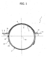
figure 1 is a front view, with parts in cross-section, of a preferred embodiment of the restraining unit for fitting a combustible gas cylinder into a motor vehicle according to the present invention; -
figure 2 shows in cross-section a detail fromfigure 1 in enlarged scale and with parts removed in the interests of clarity; - and
figures 3 and 4 show in perspective, respectively, two components of the unit infigure 1 . - In
figure 1, 1 is used to indicate a restraining unit for fitting acombustible gas cylinder 2 into a motor vehicle, in particular a methane gas cylinder stored at highpressure, having a substantially cylindrical shape with two end segments. - The
unit 1 comprises asupport structure 3, which is defined by a floor portion of the motor vehicle (not shown) and is able to be fitted in a fixed position, in a way not shown, in the motor vehicle. - The
structure 3 comprises anintermediate wall 4, the lower surface of which defines a seat orcavity 5 complimentary to the external profile of anupper portion 6 of thecylinder 2, which is laid directly on thewall 4. - The
structure 3 further comprises a substantially plane perimeter wall 7 (figure 3 ), arranged around thewall 4, implemented in a single piece with thewall 4, and comprising in its turn twolateral portions 8, which are arranged on opposite sides of theseat 5 and have respective slottedholes 9. - With reference to
figure 2 , theportions 8 carry, for eachhole 9, arespective connection element 11. Theelements 11 are defined by pins which are fixed to theportions 8, preferably by welding, protrude upwards from the upper surface of theportions 8 and are each arranged in a position adjacent to the relevant slottedhole 9, on the opposite side relative to thewall 4. - The
unit 1 comprises, furthermore, tworestraining belts 16, each of which is constituted by twometal strips hinge 18 not described in detail, so as to be able to rotate one relative to the other around a direction parallel to alongitudinal axis 19 of thecylinder 2 and of theseat 5. - Each
belt 16 carries a respective pair ofreinforcement elements 24, which are free to slide along thestrip 17a. In particular, theelements 24 compriserespective plane bases 29, which are coupled to theportions 8 by means of the interposition ofrespective seals 32 and have respective slottedholes 30 aligned with the slottedholes 9. Thestrips 17a pass through the slottedholes holes 9 are defined by ribs 31 which face each other and protrude downwards relative to the lower surface of theportions 8, so as to prevent sticking between said edges and thestrips 17a. - The
bases 29 haverespective holes 33 engaged by theelements 11 and comprise respective embossments 37 (figure 2 ), in other words portions which are raised upwards relative to the remaining part of thebases 29 and to the plane defined by theportions 8 and are obtained by stamping theelements 24. - A lateral portion of the
seals 32 is compressed and restrained between theportions seals 32 are also provided with slotted holes, so as to fit thestrip 17a, and have dimensions, positions and shape to guarantee the fluid seal around thestrip 17a through the slottedholes 9. - The
elements 24 compriserespective support walls 35, connected to thebases 24, having at least in part a curved profile complimentary to that of thewall 4, and arranged or gripped between thewall 4 itself and thestrips 17a. - With reference to
figure 3 , thestrips 17a are accommodated in respective grooves, defined by thewall 4 and by a pair ofribs 38. Theribs 38 are extended in an arc, protrude from the upper surface of thewall 4, are fixed relative to thewall 4 and restrain thewalls 35 of theelements 24 in a direction parallel to theaxis 19. - To fix the
cylinder 2, the procedure is as follows. - The motor vehicle is already pre-prepared with the
structure 3 fitted so as to define the floor platform. Thebelts 16 are assembled, in other words thestrips hinge 18 and theseals 32 and theelements 24 are fitted to thestrip 17a (figure 4 ). Then, the free ends of thestrips reference numbers 27 infigure 4 ) are made to pass through the slottedholes 9, with care taken to insert theseals 32 appropriately into the slottedholes 9. At the same time, thebases 29 of theelements 24 are brought closer to theseals 32, engaging theelements 11 in theholes 33. Fixing buttons orwashers 34 are successively inserted at pressure onto theelements 11 so as to tighten thebase 29 towards theportions 8, so as to force theseals 32 and to bind theelements 24 in the fixed position, pending closure of thebelts 16 around thecylinder 2. - To fit the
cylinder 2, the motor vehicle is first raised so as to give sufficient space underneath the platform or floor of the motor vehicle. After having positioned thecylinder 2 in theseat 5, theends 27 are brought together making thestrip 17b rotate around thehinge 18 and are fixed to each other, for example by means of a screw or pin device not described in detail, so as to close thebelts 16 in a ring and to wind completely round thecylinder 2 by interposing thewalls 4. - The procedure for disassembling the
cylinder 2 is constituted by the previous operations carried out in reverse order. - In summary, this is a restraining unit in which the
belts 16 discharge the weight of thecylinder 2 uniformly over the whole circumference arc of thewall 4. - In fact, the coupling between the
cylinder 2 and thestructure 3 is substantially integral in nature in as much as thebelt 16 is closed in a vice over the lower circumference arc of thecylinder 2, on one side, and over thewall 4 shaped as a saddle on the other side, making a single block. Because of this coupling there are no areas subject to stress concentration, typical conversely of the screw connections between belts and support structure. In other words, thebelt 16 shaped in a ring allows the forces due to the weight of thecylinder 2 to be discharged over thewhole strip 17a supported on thewall 4, uniformly distributing the loads and thereby eliminating the areas of stress concentration. - Moreover, because of the solution proposed, the floor or platform of the motor vehicle is configured to accommodate a
cylinder 2 of sufficient diameter to guarantee sufficient autonomy of the motor vehicle. At the same time, it is possible to find a proper compromise so as to guarantee the minimum height off the ground in respect of thecylinder 2 and, therefore the motor vehicle. - Moreover, since it is defined by a floor portion, the
structure 3 takes up less space, is more functional, lighter and less costly, relative to known solutions which provide for an additional support frame. - A reduction is also found in the time taken and in the costs as regards the process for assembling the
unit 1 and fitting thecylinders 2 on the motor vehicle relative to known solutions provided with an additional support frame, due to the smaller number of components to be assembled and the small number of operations to be carried out. - From what has been said above it would seem obvious, finally, that modifications and variations that do not lay outside the field of protection of the present invention may be made to the
unit 1 described. - In particular, the
structure 3 could be defined by a modular floor form.
and in that said belt means involve at least one belt passing through said slotted holes and defining a ring which, when in use, winds completely said cylinder by means of the interposition of said intermediate wall.
Claims (5)
- Restraining unit (1) for fitting a combustible gas cylinder (2) into a motor vehicle; the unit comprising:- a support structure (3) defining a seat (5) that houses, when in use, an upper portion (6) of said cylinder (2);- belt means (16) arranged, when in use, around a lower portion of said cylinder (2) and coupled to said support structure (3);characterised in that said support structure (3) is defined by a floor portion of said motor vehicle and comprises an intermediate wall (4) defining said seat (5) and two lateral wall portions (8) arranged on opposite lateral sides of said seat (5) and having respective slotted holes (9);
and in that said belt means involve at least one belt passing through said slotted holes (9) and defining a ring which, when in use, winds completely said cylinder (2) by means of the interposition of said intermediate wall (4). - Unit according to claim 1, characterised in that it comprises two reinforcement elements (24) carried by said belts and comprising respective first portions (35) coupled to said intermediate wall (4) and respective second portions (29) each coupled to a respective said lateral wall portion (8).
- Unit according to claim 1 or 2, characterised in that it comprises seal means (32) to guarantee the fluid seal through said slotted holes (9) around said belt (16).
- Unit according to claims 2 and 3, characterised in that said seal means (32) comprise two seals carried by said belt (16) and forced between said lateral wall portions (a) and said second portions (29).
- Unit according to claim 2 or 3, characterised in that it comprises connection elements (11) fixed and protruding relative to said lateral wall portions (8), and that said second portions (29) have respective holes (33) engaged by said connection elements (11).
Applications Claiming Priority (1)
| Application Number | Priority Date | Filing Date | Title |
|---|---|---|---|
| IT000721A ITTO20060721A1 (en) | 2006-10-06 | 2006-10-06 | HOLDING GROUP FOR MOUNTING A FUEL GAS CYLINDER IN A MOTOR VEHICLE |
Publications (2)
| Publication Number | Publication Date |
|---|---|
| EP1908619A1 EP1908619A1 (en) | 2008-04-09 |
| EP1908619B1 true EP1908619B1 (en) | 2009-12-09 |
Family
ID=38191367
Family Applications (1)
| Application Number | Title | Priority Date | Filing Date |
|---|---|---|---|
| EP07118000A Active EP1908619B1 (en) | 2006-10-06 | 2007-10-05 | Restraining unit for fitting a combustible gas cylinder into a motor vehicle |
Country Status (5)
| Country | Link |
|---|---|
| EP (1) | EP1908619B1 (en) |
| AT (1) | ATE451266T1 (en) |
| DE (1) | DE602007003655D1 (en) |
| ES (1) | ES2337199T3 (en) |
| IT (1) | ITTO20060721A1 (en) |
Cited By (1)
| Publication number | Priority date | Publication date | Assignee | Title |
|---|---|---|---|---|
| CN103074906A (en) * | 2011-10-25 | 2013-05-01 | 合肥杰事杰新材料股份有限公司 | Construction method of protecting pad of methane tank |
Families Citing this family (2)
| Publication number | Priority date | Publication date | Assignee | Title |
|---|---|---|---|---|
| JP5391281B2 (en) * | 2009-11-06 | 2014-01-15 | 本田技研工業株式会社 | Gas tank |
| US9193261B2 (en) | 2012-03-21 | 2015-11-24 | Agility Fuel Systems, Inc. | Strap guide and tank mounting fixture |
Family Cites Families (2)
| Publication number | Priority date | Publication date | Assignee | Title |
|---|---|---|---|---|
| DE9010169U1 (en) * | 1990-07-04 | 1990-12-20 | Zue-Re-Wi Siegfried Zuehlke, 4840 Rheda-Wiedenbrueck, De | |
| US6698212B2 (en) * | 2001-07-03 | 2004-03-02 | Thermo King Corporation | Cryogenic temperature control apparatus and method |
-
2006
- 2006-10-06 IT IT000721A patent/ITTO20060721A1/en unknown
-
2007
- 2007-10-05 EP EP07118000A patent/EP1908619B1/en active Active
- 2007-10-05 ES ES07118000T patent/ES2337199T3/en active Active
- 2007-10-05 AT AT07118000T patent/ATE451266T1/en not_active IP Right Cessation
- 2007-10-05 DE DE602007003655T patent/DE602007003655D1/en active Active
Cited By (2)
| Publication number | Priority date | Publication date | Assignee | Title |
|---|---|---|---|---|
| CN103074906A (en) * | 2011-10-25 | 2013-05-01 | 合肥杰事杰新材料股份有限公司 | Construction method of protecting pad of methane tank |
| CN103074906B (en) * | 2011-10-25 | 2015-05-20 | 合肥杰事杰新材料股份有限公司 | Construction method of protecting pad of methane tank |
Also Published As
| Publication number | Publication date |
|---|---|
| ATE451266T1 (en) | 2009-12-15 |
| DE602007003655D1 (en) | 2010-01-21 |
| ES2337199T3 (en) | 2010-04-21 |
| ITTO20060721A1 (en) | 2008-04-07 |
| EP1908619A1 (en) | 2008-04-09 |
Similar Documents
| Publication | Publication Date | Title |
|---|---|---|
| US6520124B2 (en) | Double walled fuel tank with integral generator set mounting frame | |
| EP1908619B1 (en) | Restraining unit for fitting a combustible gas cylinder into a motor vehicle | |
| CA2254192C (en) | Modular fuel tank assembly, vehicle mounting arrangement and method for installation | |
| CN104070536A (en) | Industrial robot provided with balancer device | |
| US8192104B2 (en) | Machine suspension link pin retention system | |
| JP3542947B2 (en) | Unit frame and flow meter unit | |
| US20110266073A1 (en) | Modular weighbridge | |
| KR100263370B1 (en) | Hand operated chain block | |
| US9010832B2 (en) | Multi-piece vehicle tank enclosure | |
| KR100632918B1 (en) | Saddle for auto-climbing device | |
| US6161272A (en) | Liquid storage tank apparatus and method of forming same | |
| JP7072407B2 (en) | Vehicle frame for mobile cranes and mobile cranes | |
| KR101899350B1 (en) | Terminal die assembly | |
| JP5603820B2 (en) | Anchor box | |
| KR101793363B1 (en) | Parking guide sign board | |
| KR200400009Y1 (en) | Rotation Apparatus of constructing temporary bridge | |
| KR200298713Y1 (en) | Hinge having a function of a door stopper for a switchboard | |
| CN108408276B (en) | Valve box, tank container and box door mounting structure | |
| ES2242506A1 (en) | Body cover/seat lock installation structure of scooter type vehicle | |
| KR20180086670A (en) | Water meter Box | |
| CN220054549U (en) | But mortise and tenon buckle formula reuse packing box | |
| CN210503616U (en) | Automobile instrument desk assembly packaging iron frame | |
| CN210462254U (en) | Chain type section bar connecting support | |
| CN216866065U (en) | Interim escape way of architectural design construction | |
| CN112823115B (en) | Vehicle with support structure |
Legal Events
| Date | Code | Title | Description |
|---|---|---|---|
| PUAI | Public reference made under article 153(3) epc to a published international application that has entered the european phase |
Free format text: ORIGINAL CODE: 0009012 |
|
| AK | Designated contracting states |
Kind code of ref document: A1 Designated state(s): AT BE BG CH CY CZ DE DK EE ES FI FR GB GR HU IE IS IT LI LT LU LV MC MT NL PL PT RO SE SI SK TR |
|
| AX | Request for extension of the european patent |
Extension state: AL BA HR MK RS |
|
| 17P | Request for examination filed |
Effective date: 20081008 |
|
| AKX | Designation fees paid |
Designated state(s): AT BE BG CH CY CZ DE DK EE ES FI FR GB GR HU IE IS IT LI LT LU LV MC MT NL PL PT RO SE SI SK TR |
|
| GRAP | Despatch of communication of intention to grant a patent |
Free format text: ORIGINAL CODE: EPIDOSNIGR1 |
|
| GRAS | Grant fee paid |
Free format text: ORIGINAL CODE: EPIDOSNIGR3 |
|
| GRAA | (expected) grant |
Free format text: ORIGINAL CODE: 0009210 |
|
| AK | Designated contracting states |
Kind code of ref document: B1 Designated state(s): AT BE BG CH CY CZ DE DK EE ES FI FR GB GR HU IE IS IT LI LT LU LV MC MT NL PL PT RO SE SI SK TR |
|
| REG | Reference to a national code |
Ref country code: GB Ref legal event code: FG4D |
|
| REG | Reference to a national code |
Ref country code: CH Ref legal event code: EP |
|
| REG | Reference to a national code |
Ref country code: IE Ref legal event code: FG4D |
|
| REF | Corresponds to: |
Ref document number: 602007003655 Country of ref document: DE Date of ref document: 20100121 Kind code of ref document: P |
|
| REG | Reference to a national code |
Ref country code: NL Ref legal event code: VDEP Effective date: 20091209 |
|
| REG | Reference to a national code |
Ref country code: ES Ref legal event code: FG2A Ref document number: 2337199 Country of ref document: ES Kind code of ref document: T3 |
|
| PG25 | Lapsed in a contracting state [announced via postgrant information from national office to epo] |
Ref country code: SE Free format text: LAPSE BECAUSE OF FAILURE TO SUBMIT A TRANSLATION OF THE DESCRIPTION OR TO PAY THE FEE WITHIN THE PRESCRIBED TIME-LIMIT Effective date: 20091209 Ref country code: LT Free format text: LAPSE BECAUSE OF FAILURE TO SUBMIT A TRANSLATION OF THE DESCRIPTION OR TO PAY THE FEE WITHIN THE PRESCRIBED TIME-LIMIT Effective date: 20091209 Ref country code: FI Free format text: LAPSE BECAUSE OF FAILURE TO SUBMIT A TRANSLATION OF THE DESCRIPTION OR TO PAY THE FEE WITHIN THE PRESCRIBED TIME-LIMIT Effective date: 20091209 |
|
| LTIE | Lt: invalidation of european patent or patent extension |
Effective date: 20091209 |
|
| PG25 | Lapsed in a contracting state [announced via postgrant information from national office to epo] |
Ref country code: LV Free format text: LAPSE BECAUSE OF FAILURE TO SUBMIT A TRANSLATION OF THE DESCRIPTION OR TO PAY THE FEE WITHIN THE PRESCRIBED TIME-LIMIT Effective date: 20091209 Ref country code: SI Free format text: LAPSE BECAUSE OF FAILURE TO SUBMIT A TRANSLATION OF THE DESCRIPTION OR TO PAY THE FEE WITHIN THE PRESCRIBED TIME-LIMIT Effective date: 20091209 Ref country code: PL Free format text: LAPSE BECAUSE OF FAILURE TO SUBMIT A TRANSLATION OF THE DESCRIPTION OR TO PAY THE FEE WITHIN THE PRESCRIBED TIME-LIMIT Effective date: 20091209 |
|
| PG25 | Lapsed in a contracting state [announced via postgrant information from national office to epo] |
Ref country code: AT Free format text: LAPSE BECAUSE OF FAILURE TO SUBMIT A TRANSLATION OF THE DESCRIPTION OR TO PAY THE FEE WITHIN THE PRESCRIBED TIME-LIMIT Effective date: 20091209 |
|
| PG25 | Lapsed in a contracting state [announced via postgrant information from national office to epo] |
Ref country code: EE Free format text: LAPSE BECAUSE OF FAILURE TO SUBMIT A TRANSLATION OF THE DESCRIPTION OR TO PAY THE FEE WITHIN THE PRESCRIBED TIME-LIMIT Effective date: 20091209 Ref country code: BG Free format text: LAPSE BECAUSE OF FAILURE TO SUBMIT A TRANSLATION OF THE DESCRIPTION OR TO PAY THE FEE WITHIN THE PRESCRIBED TIME-LIMIT Effective date: 20100309 Ref country code: IS Free format text: LAPSE BECAUSE OF FAILURE TO SUBMIT A TRANSLATION OF THE DESCRIPTION OR TO PAY THE FEE WITHIN THE PRESCRIBED TIME-LIMIT Effective date: 20100409 Ref country code: RO Free format text: LAPSE BECAUSE OF FAILURE TO SUBMIT A TRANSLATION OF THE DESCRIPTION OR TO PAY THE FEE WITHIN THE PRESCRIBED TIME-LIMIT Effective date: 20091209 Ref country code: NL Free format text: LAPSE BECAUSE OF FAILURE TO SUBMIT A TRANSLATION OF THE DESCRIPTION OR TO PAY THE FEE WITHIN THE PRESCRIBED TIME-LIMIT Effective date: 20091209 Ref country code: PT Free format text: LAPSE BECAUSE OF FAILURE TO SUBMIT A TRANSLATION OF THE DESCRIPTION OR TO PAY THE FEE WITHIN THE PRESCRIBED TIME-LIMIT Effective date: 20100409 |
|
| PG25 | Lapsed in a contracting state [announced via postgrant information from national office to epo] |
Ref country code: BE Free format text: LAPSE BECAUSE OF FAILURE TO SUBMIT A TRANSLATION OF THE DESCRIPTION OR TO PAY THE FEE WITHIN THE PRESCRIBED TIME-LIMIT Effective date: 20091209 Ref country code: CZ Free format text: LAPSE BECAUSE OF FAILURE TO SUBMIT A TRANSLATION OF THE DESCRIPTION OR TO PAY THE FEE WITHIN THE PRESCRIBED TIME-LIMIT Effective date: 20091209 Ref country code: SK Free format text: LAPSE BECAUSE OF FAILURE TO SUBMIT A TRANSLATION OF THE DESCRIPTION OR TO PAY THE FEE WITHIN THE PRESCRIBED TIME-LIMIT Effective date: 20091209 |
|
| PLBE | No opposition filed within time limit |
Free format text: ORIGINAL CODE: 0009261 |
|
| STAA | Information on the status of an ep patent application or granted ep patent |
Free format text: STATUS: NO OPPOSITION FILED WITHIN TIME LIMIT |
|
| PG25 | Lapsed in a contracting state [announced via postgrant information from national office to epo] |
Ref country code: GR Free format text: LAPSE BECAUSE OF FAILURE TO SUBMIT A TRANSLATION OF THE DESCRIPTION OR TO PAY THE FEE WITHIN THE PRESCRIBED TIME-LIMIT Effective date: 20100310 Ref country code: CY Free format text: LAPSE BECAUSE OF FAILURE TO SUBMIT A TRANSLATION OF THE DESCRIPTION OR TO PAY THE FEE WITHIN THE PRESCRIBED TIME-LIMIT Effective date: 20091209 |
|
| 26N | No opposition filed |
Effective date: 20100910 |
|
| PG25 | Lapsed in a contracting state [announced via postgrant information from national office to epo] |
Ref country code: DK Free format text: LAPSE BECAUSE OF FAILURE TO SUBMIT A TRANSLATION OF THE DESCRIPTION OR TO PAY THE FEE WITHIN THE PRESCRIBED TIME-LIMIT Effective date: 20091209 |
|
| PG25 | Lapsed in a contracting state [announced via postgrant information from national office to epo] |
Ref country code: IT Free format text: LAPSE BECAUSE OF FAILURE TO SUBMIT A TRANSLATION OF THE DESCRIPTION OR TO PAY THE FEE WITHIN THE PRESCRIBED TIME-LIMIT Effective date: 20091209 |
|
| PG25 | Lapsed in a contracting state [announced via postgrant information from national office to epo] |
Ref country code: MC Free format text: LAPSE BECAUSE OF NON-PAYMENT OF DUE FEES Effective date: 20101031 |
|
| PG25 | Lapsed in a contracting state [announced via postgrant information from national office to epo] |
Ref country code: IE Free format text: LAPSE BECAUSE OF NON-PAYMENT OF DUE FEES Effective date: 20101005 |
|
| PG25 | Lapsed in a contracting state [announced via postgrant information from national office to epo] |
Ref country code: MT Free format text: LAPSE BECAUSE OF FAILURE TO SUBMIT A TRANSLATION OF THE DESCRIPTION OR TO PAY THE FEE WITHIN THE PRESCRIBED TIME-LIMIT Effective date: 20091209 |
|
| REG | Reference to a national code |
Ref country code: CH Ref legal event code: PL |
|
| GBPC | Gb: european patent ceased through non-payment of renewal fee |
Effective date: 20111005 |
|
| PG25 | Lapsed in a contracting state [announced via postgrant information from national office to epo] |
Ref country code: LI Free format text: LAPSE BECAUSE OF NON-PAYMENT OF DUE FEES Effective date: 20111031 Ref country code: CH Free format text: LAPSE BECAUSE OF NON-PAYMENT OF DUE FEES Effective date: 20111031 |
|
| PG25 | Lapsed in a contracting state [announced via postgrant information from national office to epo] |
Ref country code: GB Free format text: LAPSE BECAUSE OF NON-PAYMENT OF DUE FEES Effective date: 20111005 |
|
| PG25 | Lapsed in a contracting state [announced via postgrant information from national office to epo] |
Ref country code: LU Free format text: LAPSE BECAUSE OF NON-PAYMENT OF DUE FEES Effective date: 20101005 Ref country code: HU Free format text: LAPSE BECAUSE OF FAILURE TO SUBMIT A TRANSLATION OF THE DESCRIPTION OR TO PAY THE FEE WITHIN THE PRESCRIBED TIME-LIMIT Effective date: 20100610 |
|
| PGFP | Annual fee paid to national office [announced via postgrant information from national office to epo] |
Ref country code: TR Payment date: 20120919 Year of fee payment: 6 |
|
| REG | Reference to a national code |
Ref country code: FR Ref legal event code: PLFP Year of fee payment: 10 |
|
| PG25 | Lapsed in a contracting state [announced via postgrant information from national office to epo] |
Ref country code: TR Free format text: LAPSE BECAUSE OF NON-PAYMENT OF DUE FEES Effective date: 20141005 |
|
| REG | Reference to a national code |
Ref country code: FR Ref legal event code: PLFP Year of fee payment: 11 |
|
| REG | Reference to a national code |
Ref country code: FR Ref legal event code: PLFP Year of fee payment: 12 |
|
| PGFP | Annual fee paid to national office [announced via postgrant information from national office to epo] |
Ref country code: FR Payment date: 20230920 Year of fee payment: 17 |
|
| PGFP | Annual fee paid to national office [announced via postgrant information from national office to epo] |
Ref country code: ES Payment date: 20231102 Year of fee payment: 17 |
|
| PGFP | Annual fee paid to national office [announced via postgrant information from national office to epo] |
Ref country code: DE Payment date: 20230920 Year of fee payment: 17 |