EP1908541B1 - Honing method under prestress - Google Patents
Honing method under prestress Download PDFInfo
- Publication number
- EP1908541B1 EP1908541B1 EP07116882A EP07116882A EP1908541B1 EP 1908541 B1 EP1908541 B1 EP 1908541B1 EP 07116882 A EP07116882 A EP 07116882A EP 07116882 A EP07116882 A EP 07116882A EP 1908541 B1 EP1908541 B1 EP 1908541B1
- Authority
- EP
- European Patent Office
- Prior art keywords
- cylinder
- engine block
- honing
- phase
- honing according
- Prior art date
- Legal status (The legal status is an assumption and is not a legal conclusion. Google has not performed a legal analysis and makes no representation as to the accuracy of the status listed.)
- Not-in-force
Links
- 238000000034 method Methods 0.000 title claims abstract description 47
- 230000003993 interaction Effects 0.000 claims abstract description 4
- 229910000831 Steel Inorganic materials 0.000 claims description 2
- 239000010959 steel Substances 0.000 claims description 2
- 230000001960 triggered effect Effects 0.000 claims description 2
- 238000002513 implantation Methods 0.000 description 4
- 238000010924 continuous production Methods 0.000 description 2
- 230000007547 defect Effects 0.000 description 2
- 238000007747 plating Methods 0.000 description 2
- 238000002485 combustion reaction Methods 0.000 description 1
- 238000010586 diagram Methods 0.000 description 1
- 230000000694 effects Effects 0.000 description 1
- 238000000605 extraction Methods 0.000 description 1
- 239000000446 fuel Substances 0.000 description 1
- 238000007789 sealing Methods 0.000 description 1
Images

Classifications
-
- B—PERFORMING OPERATIONS; TRANSPORTING
- B24—GRINDING; POLISHING
- B24B—MACHINES, DEVICES, OR PROCESSES FOR GRINDING OR POLISHING; DRESSING OR CONDITIONING OF ABRADING SURFACES; FEEDING OF GRINDING, POLISHING, OR LAPPING AGENTS
- B24B33/00—Honing machines or devices; Accessories therefor
- B24B33/10—Accessories
-
- B—PERFORMING OPERATIONS; TRANSPORTING
- B24—GRINDING; POLISHING
- B24B—MACHINES, DEVICES, OR PROCESSES FOR GRINDING OR POLISHING; DRESSING OR CONDITIONING OF ABRADING SURFACES; FEEDING OF GRINDING, POLISHING, OR LAPPING AGENTS
- B24B33/00—Honing machines or devices; Accessories therefor
- B24B33/02—Honing machines or devices; Accessories therefor designed for working internal surfaces of revolution, e.g. of cylindrical or conical shapes
-
- B—PERFORMING OPERATIONS; TRANSPORTING
- B24—GRINDING; POLISHING
- B24B—MACHINES, DEVICES, OR PROCESSES FOR GRINDING OR POLISHING; DRESSING OR CONDITIONING OF ABRADING SURFACES; FEEDING OF GRINDING, POLISHING, OR LAPPING AGENTS
- B24B41/00—Component parts such as frames, beds, carriages, headstocks
- B24B41/06—Work supports, e.g. adjustable steadies
Definitions
- the technical field of the invention relates to the running-in processes of the cylinders of a motor vehicle engine block. More specifically, the invention relates to a method of lapping cylinders stressed, so as to simulate the clamping forces of the cylinder head on the engine block.
- one of the ways to reduce fuel consumption is to reduce friction losses of the engine. Part of the losses occur in the friction of the segments that provide the sealing functions between the combustion chamber and the housing. To ensure this function properly it is necessary that said segments marry the best shape of the cylinder, thus requiring a certain plating force. If the cylinder is strongly deformed, there will need a strong plating force, resulting in a significant loss of friction.
- One way to reduce these friction losses is to obtain a geometry of the cylinder as perfect as possible.
- the break-in methods according to the invention make it possible to solve the aforementioned problems by creating a constraint in the engine block and having a continuous process, requiring no manual intervention. In this way, said methods remain qualitatively efficient, incorporating into the engine block to be honed a constraint representative of that caused by the tightening of the cylinder head on the engine block, and quantitatively, insofar as the various operations are carried out continuously , and therefore, over an optimized time.
- the term “station” refers both to a specific part of the lapping machine, a specific phase of the lapping process.
- special assigned to the screws, means that the screws do not perform their usual function, and are used only temporarily, only as part of the running-in process, to contribute to the stressing of the engine block.
- the subject of the present invention is a method for lapping at least one cylinder of a motor vehicle engine block, using a lapping machine comprising a support table and at least one lapping guide, said method being unfolded. in three distinct and consecutive phases, consisting initially of a roughing step, followed by a semi-finishing step and completed by a finishing step.
- the main technical feature of the method according to the invention is that said method is continuous and integrates, at each of said phases, a preliminary phase of stressing said motor unit. Indeed, in order to avoid the cylinder shape defects induced by the subsequent tightening of the cylinder head on the engine block, it is particularly desirable to lapping the cylinder under stress, to be representative of said clamping. Thus, when tightening the cylinder head on the engine block, the cylinder will maintain a perfect geometry.
- the preliminary phase of stressing takes place at the beginning of each of the three main phases of the process and stops at the end of each of said phases.
- the stress experienced by the block is effected along an axis parallel to the axis of revolution of the cylinder.
- the yoke is fixed on the engine block in an interface plane perpendicular to the axis of revolution of the cylinder, and the clamping forces are therefore in a direction perpendicular to said interface plane.
- said method includes an initial step (11) of implantation of temporary fixing elements (12) in the engine block (3).
- each preliminary phase of stressing consists of an interaction phase between said temporary fastening elements (12) and mobile stressing members (15) integral with the support table (13).
- the stressing of the engine block results from an interaction between a part of the lapping machine and an artificial part of said block.
- the artificial term is to be compared to the temporary term.
- the stressing of the motor unit requires the introduction of additional elements having no particular function at said block, outside said process.
- the implantation of said elements will last only the time necessary for the running-in of the cylinder.
- the movable members of the support table will first establish a mechanical contact with the fasteners, then exert a force on them to subject them to stress.
- the initial phase of implantation of the temporary fastening elements in the engine block is automated, so as to make this implantation reproducible and to promote the progress of the process.
- the temporary fastening elements are constituted by screws, implanted in the surface of the engine block intended to come into contact with the cylinder head, and the movable members, which are connected to an energy source, cooperate with said screws so as to to exert a traction force on them.
- the longitudinal axis of said screws is perpendicular to the contact surface of the engine block with the cylinder head, thus defining the precise direction in which the stress will be exerted.
- the energy source will help move the movable members of the support table, to exert a thrust on the screws.
- the screws have an enlarged head, and the members abut against said head, so as to be able to exert a thrust on them, after the triggering of the energy source.
- each member has an elongated piece ending in a forked end fitting around the screw, below its enlarged head.
- the energy source is constituted by a hydraulic device with a jack under pressure, able to exert a thrust on the elongated piece, so as to push the forked end against the head.
- the energy source may take other forms and be of electrical, mechanical, pneumatic or electromagnetic origin.
- each lapping cylinder is framed by four screws, equitably distributed around it.
- the screws are placed at the vertices of a regular quadrilateral such as, for example, a square or a rectangle. This symmetrical configuration makes it possible to better distribute the forces exerted on each cylinder, in the image of the forces generated by the tightening of the cylinder head on the block.
- the screws are made of high-strength steel
- the tensile force is representative of the force of the real head bolts
- the method comprises a final phase of removal of the temporary fasteners.
- This final phase which is necessary, is automated and is included in the continuous process.
- the methods according to the invention have the advantage of being reliable and reproducible since all the steps are automated and do not require of human interventions. They also have the advantage of offering a high engine block running frequency, insofar as they have a continuous course.
- a lapping machine1 used in a lapping method according to the invention capable of honing a cylinder 2 of a motor unit 3 of a motor vehicle, comprises an upper active part 4 for the lapping activity itself. , and a lower part 5 to support and convey the engine blocks 3 treated in a horizontal direction.
- the upper part 4 consists of a plurality of grinders 6, represented by agglomerated abrasive sticks of substantially cylindrical shape and whose longitudinal axis is vertical.
- a lapping machine 1 consists of three successive main stations, the first 8 being devoted to the blank, the second 9 to the semi-finishing and the third 10 to the finishing of the cylinder 2. These different run-in phases are distinguished from each other by the speed of rotation of the rods 6 and their roughness.
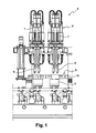
- the figure 1 illustrates the first position of the lapping machine 1 for the roughing phase of the cylinder 2.
- Each station 8, 9, 10 therefore comprises an active upper part 4 and a lower part 5 for supporting and conveying the engine blocks 3 .
- the lapping machine 1 comprises an initial station 11 automated screwing, consisting of implanting special screws 12 around each cylinder 2 of the engine block 3 to be treated, said screws 12 each having an enlarged head 22.
- Each engine block 3 has a contact surface, perpendicular to the axis of revolution of each cylinder 2 to lap and each of said cylinders 2 is flush, said surface being intended to be pressed against an equivalent surface of the cylinder head of the engine, when clamping said cylinder head on said block 3.
- Each of the special screws 12 is thus implanted in said contact surface, perpendicular thereto, the longitudinal axis of said screws 12 thus being parallel to the axis of revolution of each cylinder 2.
- each cylinder 2 is surrounded by four special screws 12 arranged at the vertices of a rectangle surrounding each of said cylinders 2.
- the lower part 5 of each of the three main stations 8, 9, 10 of the lapping machine 1, respectively concerning the blank, the semi-finishing and the finishing, comprises a horizontal support table 13 and guides 14 of laps in the form of hollow cylindrical parts, placed in line with the cylinders 2 to be treated. Said guides 14 are intended to optimize the position of each lapel 6 within each cylinder 2 to be honed.
- the support table 13 comprises a plurality of movable stressing members 15, the number of which is the same as that of the special screws 12 implanted in the engine block 3.
- Said members 15 are identical to each other and are each constituted by a horizontal base 16, able to move on the support table 13 and on which is fixed, irremovably, a rod 17 in a vertical position.
- the free end 18 of the rod 17 is slightly flared and is connected to an elongated piece 19, of in a more precise manner, one end 20 of the elongate piece 19 is connected to the free end 18 of the rod 17 to allow said piece 19 to make a movement. rotation around said free end 18.
- the other end 21 of the elongated piece 19 is forked and is intended to be placed under the head 22 of a special screw 12, and more particularly to its contact.
- a hydraulic device 23 comprising a jack 24 under pressure is implanted in the base 16 of each movable member 15 so that the jack 24 abuts against the elongated member 19.
- said elongate member 19 has a notch 25 for locking the end of the cylinder 24.
- the hydraulic device 23 is positioned on the base 16 to allow the cylinder 24 to move along an axis parallel to the longitudinal axis of the rod 17.
- a lapping machine 1 used in a lapping method according to the invention comprises a final station 26 for extracting the special screws 12 of the engine block 3, after the cylinders 2 thereof have been ground. This extraction is achieved by a simple unscrewing operation.
- the honing method according to the invention is carried out by respecting the following steps.
- An engine block 3 is routed to the initial screwing station 11 during which it receives four screws 12 per cylinder 2.
- the screws 12 are located at predetermined locations around each cylinder 2, so as to emerge quite widely from said engine block 3
- Block 3 reaches the first lapping station 8 for roughing.
- the mobile moving members 15 are then moved automatically in translation on the support table 13 following a guide path, until the forked end 21 comes to be placed under the enlarged head 22 of each of the screws 12 which emerges from said support table 13. In this way, the forked end 12 comes to grip the screw 12.
- the pneumatic devices 13 are then triggered, moving each of the cylinders 24, which will exert a thrust on the elongated piece 19, placed in abutment against the screw 12 via its end forked 21.
- the screws 12 then undergo a tensile force along their longitudinal axis tending to remove them from their location in block 3.
- Block 3 is then under stress.
- the grinders 6 descend into the cylinders 2, being assisted by the guides 14. Once correctly positioned in the cylinders 2, the grinders 6 begin to turn to lap said cylinders 2.
- the pneumatic devices 13 are deactivated and the members 15 are removed.
- the engine block 3, still fitted with its screws 12, is conveyed to the next station 9 dedicated to the semi-finishing. Block 3 is put under stress on the same diagram as the previous one.
- each station 8, 9, 10 can lapping simultaneously a variable number of cylinders 2.
Landscapes
- Engineering & Computer Science (AREA)
- Mechanical Engineering (AREA)
- Physics & Mathematics (AREA)
- Geometry (AREA)
- Finish Polishing, Edge Sharpening, And Grinding By Specific Grinding Devices (AREA)
- Saccharide Compounds (AREA)
- Steroid Compounds (AREA)
- Crystals, And After-Treatments Of Crystals (AREA)
Abstract
Description
Le domaine technique de l'invention concerne les procédés de rodage des cylindres d'un bloc moteur de véhicule automobile. Plus spécifiquement, l'invention se rapporte à un procédé de rodage de cylindres mis sous contrainte, de manière à simuler les efforts de serrage de la culasse sur le bloc moteur. En effet, un des moyens de réduction de la consommation d'essence est de réduire les pertes par frottements du moteur. Une partie des pertes se produit au niveau du frottement des segments qui assurent les fonctions d'étanchéité entre la chambre de combustion et le carter. Pour assurer correctement cette fonction il faut que lesdits segments épousent au mieux la forme du cylindre, nécessitant ainsi un certain effort de plaquage. Si le cylindre est fortement déformé, il y aura besoin d'un fort effort de plaquage, d'où une production de pertes par frottements importante. Une façon de réduire ces pertes par frottements est donc d'obtenir une géométrie du cylindre la plus parfaite possible. Une partie significative des défauts de forme provient des contraintes induites par le serrage de la culasse. Or, le rodage est réalisé sans la culasse, donc sans les contraintes dans le bloc moteur. Les procédés de rodage selon l'invention permettent de remédier à ce problème, en introduisant des contraintes avant l'opération de rodage, pour simuler les efforts dus au serrage de la culasse sur le bloc moteur.The technical field of the invention relates to the running-in processes of the cylinders of a motor vehicle engine block. More specifically, the invention relates to a method of lapping cylinders stressed, so as to simulate the clamping forces of the cylinder head on the engine block. Indeed, one of the ways to reduce fuel consumption is to reduce friction losses of the engine. Part of the losses occur in the friction of the segments that provide the sealing functions between the combustion chamber and the housing. To ensure this function properly it is necessary that said segments marry the best shape of the cylinder, thus requiring a certain plating force. If the cylinder is strongly deformed, there will need a strong plating force, resulting in a significant loss of friction. One way to reduce these friction losses is to obtain a geometry of the cylinder as perfect as possible. A significant part of the defects of form comes from the stresses induced by the tightening of the cylinder head. However, the running in is done without the cylinder head, so without the constraints in the engine block. Break-in methods according to the invention make it possible to remedy this problem, by introducing stresses before the running-in operation, to simulate the forces due to the clamping of the cylinder head on the engine block.
Des procédés de rodage de cylindres sous contrainte existent déjà. Ils consistent généralement à positionner une culasse artificielle, laissant passer la tête de rodage, et qui est serrée sur le bloc moteur, afin de restituer les efforts dans ledit bloc et sur la tablature moyennant un relief adapté. L'inconvénient majeur de ce type de procédé, est qu'il n'est pas adapté aux cadences industrielles élevées. En effet, il requiert, d'une part, un premier poste de travail supplémentaire avant l'opération de rodage, pour positionner puis serrer la fausse culasse, et, d'autre part, un deuxième poste de travail supplémentaire après rodage pour retirer ladite culasse. Il nécessite de plus, un système de convoyage des pièces d'un poste à l'autre. Ces différentes opérations annexes alourdissent grandement le procédé, et nuisent de façon significative à son rendement.Stress roll-in processes already exist. They generally consist in positioning an artificial breech, allowing the lapping head to pass, and which is clamped on the engine block, in order to restore the forces in said block and on the tablature with a suitable relief. The major disadvantage of this type of process is that it is not suitable for high industrial rates. Indeed, it requires, on the one hand, a first additional workstation before the running-in operation, to position and then tighten the false bolt, and, secondly, a second additional workstation after break-in to remove said cylinder head. It also requires a system for conveying parts from one station to another. These various ancillary operations greatly increase the process and significantly affect its performance.
Il est connu de la demande de la demande
Les procédés de rodage selon l'invention, permettent de résoudre les problèmes précités, en créant une contrainte dans le bloc moteur, et en ayant un déroulement en continu, ne nécessitant aucune intervention manuelle. De cette manière, lesdits procédés demeurent performants qualitativement, en incorporant dans le bloc moteur à roder une contrainte représentative de celle occasionnée par le serrage de la culasse sur le bloc moteur, et quantitativement, dans la mesure où les différentes opérations s'effectuent en continu, et donc, sur un temps optimisé.The break-in methods according to the invention make it possible to solve the aforementioned problems by creating a constraint in the engine block and having a continuous process, requiring no manual intervention. In this way, said methods remain qualitatively efficient, incorporating into the engine block to be honed a constraint representative of that caused by the tightening of the cylinder head on the engine block, and quantitatively, insofar as the various operations are carried out continuously , and therefore, over an optimized time.
Pour une meilleure compréhension de la description, le terme « poste » désigne tout aussi bien une partie spécifique de la machine de rodage, qu'une phase spécifique du procédé de rodage. Le terme « spéciale » attribué aux vis, signifie que les vis n'exercent pas leur fonction habituelle, et ne sont utilisées que temporairement, uniquement dans le cadre du procédé de rodage, pour contribuer à la mise sous contrainte du bloc moteur.For a better understanding of the description, the term "station" refers both to a specific part of the lapping machine, a specific phase of the lapping process. The term "special" assigned to the screws, means that the screws do not perform their usual function, and are used only temporarily, only as part of the running-in process, to contribute to the stressing of the engine block.
La présente invention a pour objet un procédé de rodage d'au moins un cylindre d'un bloc moteur de véhicule automobile, mettant en oeuvre une machine de rodage comprenant une table d'appui et au moins un guide de rodoir, ledit procédé se déroulant selon trois phases distinctes et consécutives, consistant d'abord en une étape d'ébauche, suivie d'une étape de semi finition et terminée par une étape de finition. La principale caractéristique technique du procédé selon l'invention est que ledit procédé est continu et intègre, à chacune desdites, phases, une phase préliminaire de mise sous contrainte dudit bloc moteur. En effet, afin d'éviter les défauts de forme du cylindre induits par le serrage ultérieur de la culasse sur le bloc moteur, il est particulièrement souhaitable de roder le cylindre sous contrainte, pour être représentatif dudit serrage. Ainsi, au moment du serrage de la culasse sur le bloc moteur, le cylindre conservera une géométrie parfaite. La phase préliminaire de mise sous contrainte a lieu au début de chacune des trois phases principales du procédé et s'interrompt à la fin de chacune desdites phases.The subject of the present invention is a method for lapping at least one cylinder of a motor vehicle engine block, using a lapping machine comprising a support table and at least one lapping guide, said method being unfolded. in three distinct and consecutive phases, consisting initially of a roughing step, followed by a semi-finishing step and completed by a finishing step. The main technical feature of the method according to the invention is that said method is continuous and integrates, at each of said phases, a preliminary phase of stressing said motor unit. Indeed, in order to avoid the cylinder shape defects induced by the subsequent tightening of the cylinder head on the engine block, it is particularly desirable to lapping the cylinder under stress, to be representative of said clamping. Thus, when tightening the cylinder head on the engine block, the cylinder will maintain a perfect geometry. The preliminary phase of stressing takes place at the beginning of each of the three main phases of the process and stops at the end of each of said phases.
Préférentiellement, la contrainte subie par le bloc s'effectue suivant un axe parallèle à l'axe de révolution du cylindre. En effet, la culasse vient se fixer sur le bloc moteur suivant un plan d'interface perpendiculaire à l'axe de révolution du cylindre, et les efforts de serrage ont donc lieu suivant une direction perpendiculaire audit plan d'interface.Preferably, the stress experienced by the block is effected along an axis parallel to the axis of revolution of the cylinder. Indeed, the yoke is fixed on the engine block in an interface plane perpendicular to the axis of revolution of the cylinder, and the clamping forces are therefore in a direction perpendicular to said interface plane.
Avantageusement, ledit procédé inclut une étape initiale (11) d'implantation d'éléments (12) de fixation temporaires dans le bloc moteur (3).Advantageously, said method includes an initial step (11) of implantation of temporary fixing elements (12) in the engine block (3).
De façon préférentielle, chaque phase préliminaire de mise sous contrainte consiste en une phase d'interaction entre lesdits éléments (12) de fixation temporaires et des organes (15) mobiles de mise sous contrainte, solidaires de la table d'appui (13).
Autrement dit, la mise sous contrainte du bloc moteur résulte d'une interaction entre une partie de la machine de rodage et une partie artificielle dudit bloc. Le terme artificielle est à rapprocher du terme temporaire. En effet, la mise sous contrainte du bloc moteur nécessite l'introduction d'éléments supplémentaires n'ayant aucune fonction particulière au niveau dudit bloc, en dehors dudit procédé. Ainsi, l'implantation desdits éléments ne durera que le temps nécessaire au rodage du cylindre. Les organes mobiles de la table d'appui, vont d'abord établir un contact mécanique avec les éléments de fixation, puis exercer une force sur ceux-ci afin de les soumettre à une contrainte. Préférentiellement, il existe au moins un élément de fixation par cylindre.Preferably, each preliminary phase of stressing consists of an interaction phase between said temporary fastening elements (12) and mobile stressing members (15) integral with the support table (13).
In other words, the stressing of the engine block results from an interaction between a part of the lapping machine and an artificial part of said block. The artificial term is to be compared to the temporary term. Indeed, the stressing of the motor unit requires the introduction of additional elements having no particular function at said block, outside said process. Thus, the implantation of said elements will last only the time necessary for the running-in of the cylinder. The movable members of the support table, will first establish a mechanical contact with the fasteners, then exert a force on them to subject them to stress. Preferably, there is at least one fastening element per cylinder.
Avantageusement, la phase initiale d'implantation des éléments de fixation temporaires dans le bloc moteur est automatisée, de manière à rendre reproductible cette implantation et à favoriser le déroulement du procédé.Advantageously, the initial phase of implantation of the temporary fastening elements in the engine block is automated, so as to make this implantation reproducible and to promote the progress of the process.
De façon préférentielle, les éléments de fixation temporaires sont constitués par des vis, implantées dans la surface du bloc moteur destinée à venir au contact de la culasse, et les organes mobiles, qui sont reliés à une source énergétique, coopèrent avec lesdites vis de façon à exercer une force de traction sur celles-ci. Autrement dit, l'axe longitudinal desdites vis est perpendiculaire à la surface de contact du bloc moteur avec la culasse, définissant ainsi la direction précise selon laquelle va s'exercer la contrainte. La source énergétique va contribuer à mettre en mouvement les organes mobiles de la table d'appui, pour exercer une poussée sur les vis.Preferably, the temporary fastening elements are constituted by screws, implanted in the surface of the engine block intended to come into contact with the cylinder head, and the movable members, which are connected to an energy source, cooperate with said screws so as to to exert a traction force on them. In other words, the longitudinal axis of said screws is perpendicular to the contact surface of the engine block with the cylinder head, thus defining the precise direction in which the stress will be exerted. The energy source will help move the movable members of the support table, to exert a thrust on the screws.
Avantageusement, les vis possèdent une tête élargie, et les organes viennent en butée contre ladite tête, de manière à pouvoir exercer une poussée sur celles-ci, après le déclenchement de la source énergétique.Advantageously, the screws have an enlarged head, and the members abut against said head, so as to be able to exert a thrust on them, after the triggering of the energy source.
De façon avantageuse, chaque organe possède une pièce allongée se terminant par une extrémité fourchue venant s'insérer autour de la vis, au dessous de sa tête élargie.Advantageously, each member has an elongated piece ending in a forked end fitting around the screw, below its enlarged head.
De façon préférentielle, la source énergétique est constituée par un dispositif hydraulique doté d'un vérin sous pression, apte à exercer une poussée sur la pièce allongée, de manière à repousser l'extrémité fourchue contre la tête.Preferably, the energy source is constituted by a hydraulic device with a jack under pressure, able to exert a thrust on the elongated piece, so as to push the forked end against the head.
Préférentiellement, il y a autant de vérins que d'organes mobiles de mise sous contrainte. La source énergétique peut revêtir d'autres formes et être d'origine électrique, mécanique, pneumatique ou électromagnétique.Preferably, there are as many jacks as mobile moving members. The energy source may take other forms and be of electrical, mechanical, pneumatic or electromagnetic origin.
De façon avantageuse, chaque cylindre à roder est encadré par quatre vis, équitablement réparties autour de lui. Avantageusement, les vis sont placées aux sommets d'un quadrilatère régulier comme, par exemple, un carré ou un rectangle. Cette configuration symétrique permet de mieux répartir les efforts exercés sur chaque cylindre, à l'image des efforts engendrés par le serrage de la culasse sur le bloc.Advantageously, each lapping cylinder is framed by four screws, equitably distributed around it. Advantageously, the screws are placed at the vertices of a regular quadrilateral such as, for example, a square or a rectangle. This symmetrical configuration makes it possible to better distribute the forces exerted on each cylinder, in the image of the forces generated by the tightening of the cylinder head on the block.
De façon préférentielle, les vis sont en acier haute résistancePreferably, the screws are made of high-strength steel
Avantageusement, l'effort de traction est représentatif de l'effort des vraies vis de culasseAdvantageously, the tensile force is representative of the force of the real head bolts
De façon avantageuse, le procédé comporte une phase finale de retrait des éléments de fixation temporaires. Cette phase finale, qui est nécessaire, est automatisée et est incluse dans le procédé continu.Advantageously, the method comprises a final phase of removal of the temporary fasteners. This final phase, which is necessary, is automated and is included in the continuous process.
Les procédés selon l'invention présentent l'avantage d'être fiables et reproductibles puisque toutes les étapes sont automatisées et ne nécessitent pas d'interventions humaines. Ils présentent également l'avantage d'offrir une fréquence de rodages de blocs moteurs élevée, dans la mesure où ils ont un déroulement continu.The methods according to the invention have the advantage of being reliable and reproducible since all the steps are automated and do not require of human interventions. They also have the advantage of offering a high engine block running frequency, insofar as they have a continuous course.
On donne ci-après une description détaillée d'un mode de réalisation préféré d'un procédé de rodage selon l'invention en se référant aux
- La
figure 1 est une vue de coté partielle d'une machine de rodage utilisée dans un procédé selon l'invention. - La
figure 2a est une vue de coté simplifiée montrant une partie du dispositif de mise sous contrainte d'un procédé de rodage selon l'invention. - La
figure 2b est une vue du dessus de la partie du dispositif de lafigure 2a . - La
figure 3 est une vue de coté simplifiée montrant la totalité du dispositif de mise sous contrainte d'un procédé de rodage selon l'invention, avant fonctionnement. - La
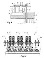
figure 4 représente le dispositif de lafigure 3 en fonctionnement. - La
figure 5 est une de coté d'une machine de rodage utilisée dans un procédé de rodage selon l'invention.
- The
figure 1 is a partial side view of a lapping machine used in a method according to the invention. - The
figure 2a is a simplified side view showing part of the stressing device of a lapping method according to the invention. - The
figure 2b is a view from above of the device part of thefigure 2a . - The
figure 3 is a simplified side view showing the entire device for stressing a lapping method according to the invention, before operation. - The
figure 4 represents the device of thefigure 3 Operating. - The
figure 5 is a side of a lapping machine used in a lapping method according to the invention.
En se référant à la
En se référant aux
En se référant aux
En se référant à la
Le procédé de rodage selon l'invention s'effectue en respectant les étapes suivantes.
Un bloc moteur 3 est acheminé vers le poste initial 11 de vissage au cours duquel il reçoit quatre vis 12 par cylindre 2. Les vis 12 sont implantées à des endroits prédéterminés autour de chaque cylindre 2, de manière à émerger assez largement dudit bloc moteur 3. Le bloc 3 parvient au premier poste 8 de rodage consacré à l'ébauche. Les organes mobiles 15 de mise sous contrainte sont alors déplacés automatiquement en translation sur la table d'appui 13 en suivant un chemin de guidage, jusqu'à ce que l'extrémité fourchue 21 vienne se placer sous la tête 22 élargie de chacune des vis 12 qui émergent de ladite table d'appui 13. De cette façon, l'extrémité fourchue 12 vient prendre en tenaille la vis 12. Les dispositifs pneumatiques 13 sont alors déclenchés, mettant en mouvement chacun des vérins 24, qui vont exercer une poussée sur la pièce allongée 19, placée en butée contre la vis 12 par l'intermédiaire de son extrémité fourchues 21. Les vis 12 subissent alors un effort de traction selon leur axe longitudinal tendant à les faire sortir de leur emplacement dans le bloc 3. Le bloc 3 se retrouve alors sous contrainte. Les rodoirs 6 descendent dans les cylindres 2 en étant assistés par les guides 14. Une fois correctement positionnés dans les cylindres 2, les rodoirs 6 se mettent à tourner pour roder lesdits cylindres 2. Après l'achèvement de cette première opération, les dispositifs pneumatiques 13 sont désactivés et les organes 15 sont retirés. Le bloc moteur 3, toujours muni de ses vis 12, est convoyé vers le poste suivant 9 dédié à la semi finition. Le bloc 3 est remis sous contrainte sur le même schéma que le précédent. L'opération se répète pour la phase de rodage consacrée à la finition 10. Une fois les trois étapes 8,9, 10 de rodage terminées, le bloc 3 arrive au poste final 26 de dévissage automatique, où les vis spéciales 12 sont alors extraites de leur logement dans ledit bloc 3. Les blocs 3 sont traités les uns à la suite des autres, sans discontinuité. Suivant les besoins circonstanciels, chaque poste 8,9,10 peut roder simultanément un nombre variable de cylindres 2.The honing method according to the invention is carried out by respecting the following steps.
An
Claims (12)
- Method of honing at least one cylinder (2) of a motor vehicle engine block (3), using a honing machine (1) comprising a platen (13) and at least one hone guide (6), the said method being performed in three distinct and consecutive phases consisting first of all of a roughing step (8) followed by a semi-finishing step (9) and ending with a finishing step (10), characterized in that the said method of continuous and incorporates, at the start of each of the said phases, a preliminary phase of stressing the said engine block (3), which is interrupted at the end of each of the said phases.
- Method of honing according to Claim 1, characterized in that the stress experienced by the block (3) is a stress along an axis parallel to the axis of revolution of the cylinder (2).
- Method of honing according to either one of Claims 1 and 2, characterized in that the said method includes an initial step (11) of installing temporary fasteners (12) in the engine block (3).
- Method of honing according to Claim 3, characterized in that each preliminary stressing phase consists in a phase of interaction between the said temporary fasteners (12) and mobile stressing members (15) secured to the platen (13).
- Method of honing according to Claim 4, characterized in that the temporary fasteners consist of bolts (12) installed in the surface of the engine block (3) that is intended to come into contact with the cylinder head, and the mobile members (15), which are connected to a source of power (23), collaborate with the said bolts (12) in such a way as to apply tension thereto.
- Method of honing according to Claim 5, characterized in that the bolts (12) have an enlarged head (22) and in that the members (15) butt against the said head (22) so as to be able to apply thrust to these once the source of power (23) has been triggered.
- Method of honing according to Claim 6, characterized in that each member (15) has an elongate piece (19) ending in a forked end (21) that is inserted around the bolt (12) under the enlarged head (22) thereof.
- Method of honing according to Claim 7, characterized in that the power source consists of a hydraulic device (23) provided with a pressurized cylinder actuator (24) able to exert thrust on the elongate piece (19) so as to push the forked end (21) back against the head (22).
- Method of honing according to any one of Claims 5 to 8, characterized in that each cylinder (2) to be honed is surrounded by four bolts (12) which are evenly distributed around it.
- Method of honing according to any one of Claims 5 to 9, characterized in that the bolts (12) are made of high tensile steel.
- Method of honing according to Claim 5, characterized in that the tensile force is representative of the force applied by the true cylinder head bolts.
- Method of honing according to Claim 3, characterized in that it involves a final phase (26) of removing the temporary fasteners (12).
Applications Claiming Priority (1)
| Application Number | Priority Date | Filing Date | Title |
|---|---|---|---|
| FR0654073A FR2906747B1 (en) | 2006-10-04 | 2006-10-04 | STRESSED RODING METHOD. |
Publications (2)
| Publication Number | Publication Date |
|---|---|
| EP1908541A1 EP1908541A1 (en) | 2008-04-09 |
| EP1908541B1 true EP1908541B1 (en) | 2009-12-16 |
Family
ID=37885831
Family Applications (1)
| Application Number | Title | Priority Date | Filing Date |
|---|---|---|---|
| EP07116882A Not-in-force EP1908541B1 (en) | 2006-10-04 | 2007-09-20 | Honing method under prestress |
Country Status (4)
| Country | Link |
|---|---|
| EP (1) | EP1908541B1 (en) |
| AT (1) | ATE451992T1 (en) |
| DE (1) | DE602007003790D1 (en) |
| FR (1) | FR2906747B1 (en) |
Families Citing this family (1)
| Publication number | Priority date | Publication date | Assignee | Title |
|---|---|---|---|---|
| DE102016205537B4 (en) * | 2016-04-04 | 2021-04-29 | Nagel Maschinen- Und Werkzeugfabrik Gmbh | Honing machine with several workstations and production line with it |
Family Cites Families (3)
| Publication number | Priority date | Publication date | Assignee | Title |
|---|---|---|---|---|
| US2006159A (en) * | 1934-09-28 | 1935-06-25 | Micromatic Hone Corp | Method of machining cylinders |
| US4117633A (en) * | 1977-09-12 | 1978-10-03 | Yother Cecil L | Honing plate |
| US4234275A (en) * | 1978-07-26 | 1980-11-18 | Clement Michael H | Method and apparatus for mounting an engine block boring machine |
-
2006
- 2006-10-04 FR FR0654073A patent/FR2906747B1/en not_active Expired - Fee Related
-
2007
- 2007-09-20 EP EP07116882A patent/EP1908541B1/en not_active Not-in-force
- 2007-09-20 AT AT07116882T patent/ATE451992T1/en not_active IP Right Cessation
- 2007-09-20 DE DE602007003790T patent/DE602007003790D1/en active Active
Also Published As
| Publication number | Publication date |
|---|---|
| FR2906747A1 (en) | 2008-04-11 |
| EP1908541A1 (en) | 2008-04-09 |
| DE602007003790D1 (en) | 2010-01-28 |
| FR2906747B1 (en) | 2009-05-15 |
| ATE451992T1 (en) | 2010-01-15 |
Similar Documents
| Publication | Publication Date | Title |
|---|---|---|
| EP3066303B1 (en) | Cutting tool holder for a tunnel-boring machine and associated cutting assembly | |
| EP2516791B1 (en) | Method for replacing a tunnel boring machine disk cutter, handling device and disk cutter suited to such a method | |
| EP2516220B1 (en) | Method and system for mounting or removing a motor vehicle battery | |
| EP0271399B1 (en) | Method and installation for assembling and dismantling the screws of an extruding machine | |
| EP2517283B1 (en) | Tool for the mounting/removal of a motor vehicle battery | |
| EP2646179A1 (en) | Equipment and method for changing cylinders and/or clusters of a roll stand; locking and clamping system; and roll stand comprising such systems | |
| FR2988040A1 (en) | SYSTEM FOR LOCKING / UNLOCKING AN OBJECT ON A STRUCTURE WITH SUPPORT AND ALIGNMENT ELEMENTS INTEGRATED TO TOOLS | |
| FR2783235A1 (en) | MACHINE FOR LAYING LABEL SLEEVES ON BOTTLES | |
| FR2721843A1 (en) | CONTINUOUS CASTING ARRANGEMENT BETWEEN CYLINDERS WITH APPLIED SIDE SHUTTER WALLS | |
| EP1908541A1 (en) | Honing method under prestress | |
| EP4117835B1 (en) | Tool and method for changing the working roll in a rolling mill | |
| FR2960227A1 (en) | Device for use on transport device of surface treatment installation in removable way to support and drive e.g. stopper undergoing surface treatment in e.g. cosmetic field, has support head receiving part and/or accessory from part support | |
| EP4194119B1 (en) | Multitasking device including means for evacuating a rivet or temporary fastener identified as inconformal to a waste zone | |
| CH642890A5 (en) | METHOD AND MACHINE FOR DEBURRING OR TRIMMING A CAST IRON PIPE ASSEMBLY. | |
| FR2476527A1 (en) | RETENTION DEVICE OF PARTS FOR HONING OPERATIONS | |
| EP0867253B1 (en) | Method and device for extracting and supplying the electrodes of/to an electrode gun of a resistance spot welding apparatus | |
| FR2617773A1 (en) | SYSTEM FOR MOVING A MOTOR GROUP FROM A VEHICLE COMPARTMENT | |
| EP4090511A1 (en) | Extrusion machine using an articulated roller chain to engage and guide an extruded profile member against a cooling roller | |
| FR2658587A1 (en) | Installation for handling gas cylinder caps, before and after filling these cylinders | |
| EP0094882B1 (en) | Fuel assemblies compacting and terminal pieces withdrawal machine | |
| FR3071238A1 (en) | BELT CONVEYOR AND METHOD OF EXTRACTING THE STRIP | |
| FR3147725A1 (en) | Rolling mill installation comprising a robotic system configured for the extraction of cylinders from a rolling mill and a tool changing magazine | |
| EP3031601B1 (en) | Method for stripping a construction element from a vibrating press | |
| FR2884747A1 (en) | Cylindrical shaped concrete specimen grinding machine for verifying quality of utilized concrete, has two milling/rectification mullers, each mounted, with respect to rigid main frame, on muller carriage and guided in rotation on carriage | |
| EP2111950B1 (en) | Shot blasting device and method |
Legal Events
| Date | Code | Title | Description |
|---|---|---|---|
| PUAI | Public reference made under article 153(3) epc to a published international application that has entered the european phase |
Free format text: ORIGINAL CODE: 0009012 |
|
| AK | Designated contracting states |
Kind code of ref document: A1 Designated state(s): AT BE BG CH CY CZ DE DK EE ES FI FR GB GR HU IE IS IT LI LT LU LV MC MT NL PL PT RO SE SI SK TR |
|
| AX | Request for extension of the european patent |
Extension state: AL BA HR MK RS |
|
| 17P | Request for examination filed |
Effective date: 20080826 |
|
| 17Q | First examination report despatched |
Effective date: 20080925 |
|
| AKX | Designation fees paid |
Designated state(s): AT BE BG CH CY CZ DE DK EE ES FI FR GB GR HU IE IS IT LI LT LU LV MC MT NL PL PT RO SE SI SK TR |
|
| GRAP | Despatch of communication of intention to grant a patent |
Free format text: ORIGINAL CODE: EPIDOSNIGR1 |
|
| GRAS | Grant fee paid |
Free format text: ORIGINAL CODE: EPIDOSNIGR3 |
|
| GRAA | (expected) grant |
Free format text: ORIGINAL CODE: 0009210 |
|
| AK | Designated contracting states |
Kind code of ref document: B1 Designated state(s): AT BE BG CH CY CZ DE DK EE ES FI FR GB GR HU IE IS IT LI LT LU LV MC MT NL PL PT RO SE SI SK TR |
|
| REG | Reference to a national code |
Ref country code: GB Ref legal event code: FG4D Free format text: NOT ENGLISH |
|
| REG | Reference to a national code |
Ref country code: CH Ref legal event code: EP |
|
| REG | Reference to a national code |
Ref country code: IE Ref legal event code: FG4D |
|
| REF | Corresponds to: |
Ref document number: 602007003790 Country of ref document: DE Date of ref document: 20100128 Kind code of ref document: P |
|
| REG | Reference to a national code |
Ref country code: GB Ref legal event code: 746 Effective date: 20100215 |
|
| REG | Reference to a national code |
Ref country code: NL Ref legal event code: VDEP Effective date: 20091216 |
|
| PG25 | Lapsed in a contracting state [announced via postgrant information from national office to epo] |
Ref country code: LT Free format text: LAPSE BECAUSE OF FAILURE TO SUBMIT A TRANSLATION OF THE DESCRIPTION OR TO PAY THE FEE WITHIN THE PRESCRIBED TIME-LIMIT Effective date: 20091216 Ref country code: SE Free format text: LAPSE BECAUSE OF FAILURE TO SUBMIT A TRANSLATION OF THE DESCRIPTION OR TO PAY THE FEE WITHIN THE PRESCRIBED TIME-LIMIT Effective date: 20091216 Ref country code: FI Free format text: LAPSE BECAUSE OF FAILURE TO SUBMIT A TRANSLATION OF THE DESCRIPTION OR TO PAY THE FEE WITHIN THE PRESCRIBED TIME-LIMIT Effective date: 20091216 |
|
| LTIE | Lt: invalidation of european patent or patent extension |
Effective date: 20091216 |
|
| PG25 | Lapsed in a contracting state [announced via postgrant information from national office to epo] |
Ref country code: SI Free format text: LAPSE BECAUSE OF FAILURE TO SUBMIT A TRANSLATION OF THE DESCRIPTION OR TO PAY THE FEE WITHIN THE PRESCRIBED TIME-LIMIT Effective date: 20091216 Ref country code: PL Free format text: LAPSE BECAUSE OF FAILURE TO SUBMIT A TRANSLATION OF THE DESCRIPTION OR TO PAY THE FEE WITHIN THE PRESCRIBED TIME-LIMIT Effective date: 20091216 Ref country code: LV Free format text: LAPSE BECAUSE OF FAILURE TO SUBMIT A TRANSLATION OF THE DESCRIPTION OR TO PAY THE FEE WITHIN THE PRESCRIBED TIME-LIMIT Effective date: 20091216 |
|
| PG25 | Lapsed in a contracting state [announced via postgrant information from national office to epo] |
Ref country code: AT Free format text: LAPSE BECAUSE OF FAILURE TO SUBMIT A TRANSLATION OF THE DESCRIPTION OR TO PAY THE FEE WITHIN THE PRESCRIBED TIME-LIMIT Effective date: 20091216 |
|
| REG | Reference to a national code |
Ref country code: IE Ref legal event code: FD4D |
|
| PG25 | Lapsed in a contracting state [announced via postgrant information from national office to epo] |
Ref country code: NL Free format text: LAPSE BECAUSE OF FAILURE TO SUBMIT A TRANSLATION OF THE DESCRIPTION OR TO PAY THE FEE WITHIN THE PRESCRIBED TIME-LIMIT Effective date: 20091216 Ref country code: RO Free format text: LAPSE BECAUSE OF FAILURE TO SUBMIT A TRANSLATION OF THE DESCRIPTION OR TO PAY THE FEE WITHIN THE PRESCRIBED TIME-LIMIT Effective date: 20091216 Ref country code: IS Free format text: LAPSE BECAUSE OF FAILURE TO SUBMIT A TRANSLATION OF THE DESCRIPTION OR TO PAY THE FEE WITHIN THE PRESCRIBED TIME-LIMIT Effective date: 20100416 Ref country code: PT Free format text: LAPSE BECAUSE OF FAILURE TO SUBMIT A TRANSLATION OF THE DESCRIPTION OR TO PAY THE FEE WITHIN THE PRESCRIBED TIME-LIMIT Effective date: 20100416 Ref country code: IE Free format text: LAPSE BECAUSE OF FAILURE TO SUBMIT A TRANSLATION OF THE DESCRIPTION OR TO PAY THE FEE WITHIN THE PRESCRIBED TIME-LIMIT Effective date: 20091216 Ref country code: BG Free format text: LAPSE BECAUSE OF FAILURE TO SUBMIT A TRANSLATION OF THE DESCRIPTION OR TO PAY THE FEE WITHIN THE PRESCRIBED TIME-LIMIT Effective date: 20100316 Ref country code: EE Free format text: LAPSE BECAUSE OF FAILURE TO SUBMIT A TRANSLATION OF THE DESCRIPTION OR TO PAY THE FEE WITHIN THE PRESCRIBED TIME-LIMIT Effective date: 20091216 Ref country code: ES Free format text: LAPSE BECAUSE OF FAILURE TO SUBMIT A TRANSLATION OF THE DESCRIPTION OR TO PAY THE FEE WITHIN THE PRESCRIBED TIME-LIMIT Effective date: 20100327 |
|
| PG25 | Lapsed in a contracting state [announced via postgrant information from national office to epo] |
Ref country code: CZ Free format text: LAPSE BECAUSE OF FAILURE TO SUBMIT A TRANSLATION OF THE DESCRIPTION OR TO PAY THE FEE WITHIN THE PRESCRIBED TIME-LIMIT Effective date: 20091216 Ref country code: SK Free format text: LAPSE BECAUSE OF FAILURE TO SUBMIT A TRANSLATION OF THE DESCRIPTION OR TO PAY THE FEE WITHIN THE PRESCRIBED TIME-LIMIT Effective date: 20091216 |
|
| PLBE | No opposition filed within time limit |
Free format text: ORIGINAL CODE: 0009261 |
|
| STAA | Information on the status of an ep patent application or granted ep patent |
Free format text: STATUS: NO OPPOSITION FILED WITHIN TIME LIMIT |
|
| PG25 | Lapsed in a contracting state [announced via postgrant information from national office to epo] |
Ref country code: GR Free format text: LAPSE BECAUSE OF FAILURE TO SUBMIT A TRANSLATION OF THE DESCRIPTION OR TO PAY THE FEE WITHIN THE PRESCRIBED TIME-LIMIT Effective date: 20100317 Ref country code: CY Free format text: LAPSE BECAUSE OF FAILURE TO SUBMIT A TRANSLATION OF THE DESCRIPTION OR TO PAY THE FEE WITHIN THE PRESCRIBED TIME-LIMIT Effective date: 20091216 |
|
| 26N | No opposition filed |
Effective date: 20100917 |
|
| PG25 | Lapsed in a contracting state [announced via postgrant information from national office to epo] |
Ref country code: DK Free format text: LAPSE BECAUSE OF FAILURE TO SUBMIT A TRANSLATION OF THE DESCRIPTION OR TO PAY THE FEE WITHIN THE PRESCRIBED TIME-LIMIT Effective date: 20091216 |
|
| BERE | Be: lapsed |
Owner name: PEUGEOT CITROEN AUTOMOBILES S.A. Effective date: 20100930 |
|
| PG25 | Lapsed in a contracting state [announced via postgrant information from national office to epo] |
Ref country code: IT Free format text: LAPSE BECAUSE OF FAILURE TO SUBMIT A TRANSLATION OF THE DESCRIPTION OR TO PAY THE FEE WITHIN THE PRESCRIBED TIME-LIMIT Effective date: 20091216 |
|
| PG25 | Lapsed in a contracting state [announced via postgrant information from national office to epo] |
Ref country code: MC Free format text: LAPSE BECAUSE OF NON-PAYMENT OF DUE FEES Effective date: 20100930 |
|
| PG25 | Lapsed in a contracting state [announced via postgrant information from national office to epo] |
Ref country code: BE Free format text: LAPSE BECAUSE OF NON-PAYMENT OF DUE FEES Effective date: 20100930 |
|
| PGFP | Annual fee paid to national office [announced via postgrant information from national office to epo] |
Ref country code: GB Payment date: 20110830 Year of fee payment: 5 |
|
| PG25 | Lapsed in a contracting state [announced via postgrant information from national office to epo] |
Ref country code: MT Free format text: LAPSE BECAUSE OF FAILURE TO SUBMIT A TRANSLATION OF THE DESCRIPTION OR TO PAY THE FEE WITHIN THE PRESCRIBED TIME-LIMIT Effective date: 20091216 |
|
| REG | Reference to a national code |
Ref country code: CH Ref legal event code: PL |
|
| PG25 | Lapsed in a contracting state [announced via postgrant information from national office to epo] |
Ref country code: LI Free format text: LAPSE BECAUSE OF NON-PAYMENT OF DUE FEES Effective date: 20110930 Ref country code: CH Free format text: LAPSE BECAUSE OF NON-PAYMENT OF DUE FEES Effective date: 20110930 |
|
| PG25 | Lapsed in a contracting state [announced via postgrant information from national office to epo] |
Ref country code: LU Free format text: LAPSE BECAUSE OF NON-PAYMENT OF DUE FEES Effective date: 20100920 Ref country code: HU Free format text: LAPSE BECAUSE OF FAILURE TO SUBMIT A TRANSLATION OF THE DESCRIPTION OR TO PAY THE FEE WITHIN THE PRESCRIBED TIME-LIMIT Effective date: 20100617 |
|
| PG25 | Lapsed in a contracting state [announced via postgrant information from national office to epo] |
Ref country code: TR Free format text: LAPSE BECAUSE OF FAILURE TO SUBMIT A TRANSLATION OF THE DESCRIPTION OR TO PAY THE FEE WITHIN THE PRESCRIBED TIME-LIMIT Effective date: 20091216 |
|
| PGFP | Annual fee paid to national office [announced via postgrant information from national office to epo] |
Ref country code: DE Payment date: 20120827 Year of fee payment: 6 Ref country code: FR Payment date: 20121004 Year of fee payment: 6 |
|
| GBPC | Gb: european patent ceased through non-payment of renewal fee |
Effective date: 20120920 |
|
| PG25 | Lapsed in a contracting state [announced via postgrant information from national office to epo] |
Ref country code: GB Free format text: LAPSE BECAUSE OF NON-PAYMENT OF DUE FEES Effective date: 20120920 |
|
| REG | Reference to a national code |
Ref country code: DE Ref legal event code: R119 Ref document number: 602007003790 Country of ref document: DE Effective date: 20140401 |
|
| REG | Reference to a national code |
Ref country code: FR Ref legal event code: ST Effective date: 20140530 |
|
| PG25 | Lapsed in a contracting state [announced via postgrant information from national office to epo] |
Ref country code: DE Free format text: LAPSE BECAUSE OF NON-PAYMENT OF DUE FEES Effective date: 20140401 Ref country code: FR Free format text: LAPSE BECAUSE OF NON-PAYMENT OF DUE FEES Effective date: 20130930 |