EP1908532B1 - Flexibles Luftabsugsystem - Google Patents
Flexibles Luftabsugsystem Download PDFInfo
- Publication number
- EP1908532B1 EP1908532B1 EP07018693A EP07018693A EP1908532B1 EP 1908532 B1 EP1908532 B1 EP 1908532B1 EP 07018693 A EP07018693 A EP 07018693A EP 07018693 A EP07018693 A EP 07018693A EP 1908532 B1 EP1908532 B1 EP 1908532B1
- Authority
- EP
- European Patent Office
- Prior art keywords
- nozzles
- air
- hoses
- nozzle
- flanges
- Prior art date
- Legal status (The legal status is an assumption and is not a legal conclusion. Google has not performed a legal analysis and makes no representation as to the accuracy of the status listed.)
- Active
Links
Images

Classifications
-
- B—PERFORMING OPERATIONS; TRANSPORTING
- B08—CLEANING
- B08B—CLEANING IN GENERAL; PREVENTION OF FOULING IN GENERAL
- B08B15/00—Preventing escape of dirt or fumes from the area where they are produced; Collecting or removing dirt or fumes from that area
- B08B15/02—Preventing escape of dirt or fumes from the area where they are produced; Collecting or removing dirt or fumes from that area using chambers or hoods covering the area
-
- B—PERFORMING OPERATIONS; TRANSPORTING
- B08—CLEANING
- B08B—CLEANING IN GENERAL; PREVENTION OF FOULING IN GENERAL
- B08B15/00—Preventing escape of dirt or fumes from the area where they are produced; Collecting or removing dirt or fumes from that area
- B08B15/002—Preventing escape of dirt or fumes from the area where they are produced; Collecting or removing dirt or fumes from that area using a central suction system, e.g. for collecting exhaust gases in workshops
-
- B—PERFORMING OPERATIONS; TRANSPORTING
- B08—CLEANING
- B08B—CLEANING IN GENERAL; PREVENTION OF FOULING IN GENERAL
- B08B15/00—Preventing escape of dirt or fumes from the area where they are produced; Collecting or removing dirt or fumes from that area
- B08B15/007—Fume suction nozzles arranged on a closed or semi-closed surface, e.g. on a circular, ring-shaped or rectangular surface adjacent the area where fumes are produced
Definitions
- the invention relates to an air extraction and filtering system according to the preamble of claim 1.
- the case of a shipyard and, in particular, the construction of hulls in resin and their varnishing in other words, a working process which development varies from time to time in function of the dimensions of the hulls to varnish that necessarily have to be worked in the same space where a totally different processing has been done on other hulls.
- the shipyards use a system of scaffolds to wrap up the hull, in accordance with the specific case, either the whole hull or one of its sides, and eventually also the upper surface of the hull or a part of it, with plastic material, generally transparent, in order to create a tunnel like space that provides isolation between the working area where the varnishing process is being done and the surroundings.
- plastic material generally transparent
- the pavement where the hull is being placed is indicated as nr. (1), as nr. (2) the hull, the transparent wrapping of the upper part of the hull as nr. (3) and as nr. (4) the farthest part of the lateral transparent wrapping realized on a scaffold construction. Both wrappings are an example of a tunnel like space in the shipbuilding industry.
- a known system such as the one disclosed in US6395047 , having the features of the preamble of the annexed independent claim, comprises a plurality of hose lines with end aspiration nozzles which can be put in different points of the working area.
- the adaptability of this system to the conformation of the working area is limited.
- the object of the present invention is to provide an air extraction and filtering system for extraction and filtration of toxic agents which makes possible the dislocation of the air intake units, that is the vapors and solvents intake units, in several points along the inside area of the tunnel and to put in activity one or more of these by simple operations also during the working process.
- This enables to shorten considerably the distance the air has to cross from the point where the vapors are generated to the point of air intake and to increase in considerable way the air speed inside the hoses in order to avoid this way, or at least to limit, the depositing of condensed vapors or powder.
- the invention consists of a component constituted by an aspiration nozzle, fitted in a way to have two ends, generally opposite, two flanges that enable a quick connection to hose elements that form a hose line for airflow, or in case of an eventual terminal nozzle, a final plug.
- the nozzle furthermore, is equipped with one or more closable openings, in general to be opened separately, that enable to conform the nozzle either as a flow through or as an air aspiration unit and in case of more openings present, to vary the air intake capacity of the nozzle.
- the nozzles may be equipped with more than one opening, as already mentioned, eventually to be closed separately, in order to choke the air flow of one specific nozzle part of the installation and enable, for example, the use of two neighboring nozzles choking the air flow of the nozzle closest to the aspiration point, avoiding in this way the air flow entering to concentrate exclusively on one nozzle and, more in general, to utilize optimally the potential of the aspirator, or of the aspirators, in function of the air intake units necessary .
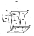
- the nozzles might be realized in metal or plastic material of a prism similar form on hexagonal basis see fig. 2 , the variation of form and constructive solution without going out of the invention.
- the nozzles might have, without going out of the invention, all the combinations in number of closable flaps.
- the flaps might be hinged up on one side to be opened and closed easily, remaining the possibility to use any solution, comprising rotation on an axis that enables a total or partial opening of a slit of semi circular form or a different one, or a system that enables the total removal of the flap, as stopper.
- nr. (5) there is the body of the aspiration nozzle, as nr. (6) the flanges for hose connection, as nr. (7) the flap for covering the opening in closure position, as nr. (8) the flap in open position and as nr. (9) the opening for air intake.
- the extremities of the nozzle might be usefully conformed by means of a connector in iron, in plastic material or any combination of materials and construction technique that makes possible the connection between the body of the nozzle and the hose conducting the air flow aspirated.
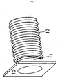
- a connection between the nozzle, as illustrated, and a conduct of circular section In particular, indicated as nr. (10) there is the flange attached to the hose that matches the flange on the aspiration nozzle and as nr. (11) the junction for the circular section hose. Indicated as nr. (12) there is the hose, in this specific case, flexible.
- the unit composed of the body of the nozzle, the flap/s and the flanges is named "aspiration nozzle”.
- Two or more nozzles connected together, attached to one or more aspirators by means of a hose line carrying air and varnish vapors conform the so called "modular air extraction and filtration system".
- connection between aspiration nozzles and the aspirator, or aspirators might be done, as pictured, by means of flexible hoses of circle section, without these being considered a limitation to the protection of this invention, making possible the use of other sections for the conduct and/or every combination of rigid, semi rigid or flexible material permitting the aspiration inside the tunnel or, however, in a narrow and long workspace.
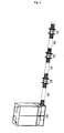
- fig. 4 a solution that makes possible the setting up of the installation according to the above described characteristics.
- fig. 4 indicated as nr. 13 there are the nozzles, as nr. 14 the hoses and as nr. 15 the aspirator placed on one extremity of the installation.
Landscapes
- Filtering Of Dispersed Particles In Gases (AREA)
- Absorbent Articles And Supports Therefor (AREA)
- Nozzles For Electric Vacuum Cleaners (AREA)
- Manipulator (AREA)
- Details Or Accessories Of Spraying Plant Or Apparatus (AREA)
- External Artificial Organs (AREA)
Claims (9)
- Luftabsaug- und -filtersystem zur Absaugung und Filtration von toxischen Stoffen, wie Lösungsmittel-, Harz- oder Lackdämpfen, die beim Lackieren oder bei Harzanwendungsprozessen erhalten werden, die in einem Arbeitsbereich ausgeführt werden, welches System Absaugeinrichtungen (15), eine Mehrzahl von Düsen (13) mit einer oder mehreren verschließbaren Öffnung(en) und eingepasste Schläuche (14) enthält, um die Düsen (13) miteinander zu verbinden, dadurch gekennzeichnet, dass die Düsen und Schläuche durch entsprechende modulare Elemente mit Flanschen (6; 10) definiert sind, die eine schnelle Verbindung zum Zusammensetzen wenigstens einer Schlauchleitung ermöglichen, wodurch der Aufbau der Leitung oder Leitungen und die Anzahl und Position der Düsen (13) an die Gestalt des Arbeitsbereichs und an die Punkte anpassbar sind, wo die toxischen Stoffe erzeugt werden.
- System nach Anspruch 1, wobei jede der Düsen (13) zwei oder mehr Öffnungen (9) enthält, die separat zu schließen sind.
- System nach Anspruch 1 oder 2, wobei jede besagte Düse zwei oder mehr Klappen (7, 8) zum Verschluss der Luftansaugöffnung (9) enthält.
- System nach einem der vorhergehenden Ansprüche, wobei jede der Düsen enthält einen Körper (5) mit zwei axialen Enden, die allgemein entgegengesetzt sind, zwei Flanschen (6) an den jeweiligen Enden des Körpers (5) zur Verbindung mit entsprechenden Schläuchen (14) oder mit einem Abschlussstopfen, eine Luftansaugöffnung (9), die in dem Körper (5) ausgebildet ist, und zwei Klappen (7, 8), die an dem Körper (5) angelenkt sind, zum Verschließen der Luftansaugöffnung (9), um separat geöffnet zu werden, um es zu gestatten, die Luftansaugkapazität der Düse (13) zu variieren.
- System nach Anspruch 4, wobei der Körper (5) eine prismatische Form hat, wobei die Öffnung (9) in einer flachen Seite des Körpers (5) ausgebildet ist.
- System nach Anspruch 4 oder 5, wobei jeder Schlauch (14) an entsprechenden axialen Enden Flansche (10) zur schnellen Verbindung mit den Flanschen (6) der Düse (13) enthält.
- System nach einem der vorhergehenden Ansprüche, wobei wenigstens eine der Düsen (13) zumindest eine Vorrichtung zum Drosseln des Luftstroms enthält.
- System nach einem der vorhergehenden Ansprüche, wobei die Schläuche (14) flexibel sind.
- System nach einem der vorhergehenden Ansprüche, wobei der Arbeitsbereich durch einen Umhüllungstunnel, Gerüste oder eine andere Art eines Segregationssystems definiert ist.
Applications Claiming Priority (1)
| Application Number | Priority Date | Filing Date | Title |
|---|---|---|---|
| IT000009A ITPO20060009A1 (it) | 2006-10-02 | 2006-10-02 | Sistema di aspirazione localizzato, modulare e componibile dotato di bocchette apribili o parzializzabili |
Publications (2)
| Publication Number | Publication Date |
|---|---|
| EP1908532A1 EP1908532A1 (de) | 2008-04-09 |
| EP1908532B1 true EP1908532B1 (de) | 2010-07-07 |
Family
ID=38922452
Family Applications (1)
| Application Number | Title | Priority Date | Filing Date |
|---|---|---|---|
| EP07018693A Active EP1908532B1 (de) | 2006-10-02 | 2007-09-24 | Flexibles Luftabsugsystem |
Country Status (5)
| Country | Link |
|---|---|
| EP (1) | EP1908532B1 (de) |
| AT (1) | ATE473060T1 (de) |
| DE (1) | DE602007007555D1 (de) |
| ES (1) | ES2348185T3 (de) |
| IT (1) | ITPO20060009A1 (de) |
Family Cites Families (8)
| Publication number | Priority date | Publication date | Assignee | Title |
|---|---|---|---|---|
| AT259822B (de) * | 1965-04-22 | 1968-02-12 | Schwarz Walter | Lüftungsanlage |
| DE29620172U1 (de) * | 1996-11-20 | 1997-02-27 | Kramer & Best Anlagenbau GmbH, 56281 Dörth | Mehlentstaubungsanlage |
| DE19920058A1 (de) * | 1999-05-03 | 2000-11-09 | Esta Apparatebau | Absaugvorrichtung und Verfahren zum Betrieb derselben |
| DE10106672B4 (de) * | 2001-02-14 | 2004-03-18 | Koenig & Bauer Ag | Längsschneideinrichtung |
| US6395047B1 (en) * | 2001-02-16 | 2002-05-28 | William C. Smith | Portable airborne contamination control system including a main and remote unit |
| US6669547B2 (en) * | 2001-08-28 | 2003-12-30 | Board Of Regents Of University Of Nebraska | Multi-stack exhaust system |
| DE10234637B4 (de) * | 2002-07-29 | 2013-10-17 | DüRR DENTAL AG | Sauganlage für den zahnmedizinischen Einsatz |
| US20060154595A1 (en) * | 2005-01-06 | 2006-07-13 | International Business Machines Corporation | Static pressure stabilizer for local exhaust |
-
2006
- 2006-10-02 IT IT000009A patent/ITPO20060009A1/it unknown
-
2007
- 2007-09-24 AT AT07018693T patent/ATE473060T1/de not_active IP Right Cessation
- 2007-09-24 ES ES07018693T patent/ES2348185T3/es active Active
- 2007-09-24 EP EP07018693A patent/EP1908532B1/de active Active
- 2007-09-24 DE DE602007007555T patent/DE602007007555D1/de active Active
Also Published As
| Publication number | Publication date |
|---|---|
| DE602007007555D1 (de) | 2010-08-19 |
| ATE473060T1 (de) | 2010-07-15 |
| ES2348185T3 (es) | 2010-12-01 |
| EP1908532A1 (de) | 2008-04-09 |
| ITPO20060009A1 (it) | 2008-04-03 |
Similar Documents
| Publication | Publication Date | Title |
|---|---|---|
| CN104185512B (zh) | 抽出含有过喷的工艺空气的方法和装置及涂覆物体的设备 | |
| CN207966923U (zh) | 晶元处理设备的排气装置 | |
| EP2290298A3 (de) | Einrichtung zum Umleiten eines Luftstroms insbesondere für eine Dunstabzugshaube | |
| KR101884239B1 (ko) | 이동식 독성가스저감장치 | |
| ITRE20120007A1 (it) | Cartuccia filtrante | |
| EP1908532A1 (de) | Flexibles Luftabsugsystem | |
| JP6982187B2 (ja) | 散布アセンブリ、及び農業植物保護機 | |
| CN103381412A (zh) | 除尘装置 | |
| CN113198662B (zh) | 一种防腐管道用环保型喷涂装置 | |
| KR20090111902A (ko) | 정수기필터 조립장치 및 그 방법 | |
| CN205710989U (zh) | 一种可清洗烘干一体化的汽车配件电泳漆处理机 | |
| CN209967973U (zh) | 一种喷漆件烘干车间废气净化装置 | |
| CA2403734A1 (en) | Cabinets for handling toxic or sterile materials | |
| CN202555553U (zh) | 除尘装置 | |
| CN104436933A (zh) | 一种水式除尘装置 | |
| CN115970949A (zh) | 一种干式喷漆室 | |
| CN210079236U (zh) | 一种烟气脱硫脱销处理装置 | |
| CN209773016U (zh) | 自净型通风柜 | |
| KR101173438B1 (ko) | 배출량 변동 대기오염 발생원 적용 다중후드 국소배기방법 및 이에 사용되는 국소배기장치 | |
| KR101884240B1 (ko) | 처리효율이 개선된 이동식 독성가스저감장치 | |
| CN208178384U (zh) | 有害气体去除装置及冷芯制芯机 | |
| CN207137601U (zh) | 一种带有过滤装置的复合机烘道 | |
| CN210413898U (zh) | 玻璃磨边机的磨轮冷却装置 | |
| CN109173467A (zh) | 一种烟尘处理一体化装置 | |
| CN221602336U (zh) | 用于喷涂装置的漆雾回收设备 |
Legal Events
| Date | Code | Title | Description |
|---|---|---|---|
| PUAI | Public reference made under article 153(3) epc to a published international application that has entered the european phase |
Free format text: ORIGINAL CODE: 0009012 |
|
| AK | Designated contracting states |
Kind code of ref document: A1 Designated state(s): AT BE BG CH CY CZ DE DK EE ES FI FR GB GR HU IE IS IT LI LT LU LV MC MT NL PL PT RO SE SI SK TR |
|
| AX | Request for extension of the european patent |
Extension state: AL BA HR MK RS |
|
| RIN1 | Information on inventor provided before grant (corrected) |
Inventor name: GHILARDI, GIANLUIGI Inventor name: CARRAI, CARLO ALBERTO Inventor name: BERTACCA, ALESSANDRO |
|
| RIN1 | Information on inventor provided before grant (corrected) |
Inventor name: BERTACCA, ALESSANDRO Inventor name: GHILARDI, GIANLUIGI Inventor name: CARRAI, CARLO ALBERTO |
|
| 17P | Request for examination filed |
Effective date: 20081007 |
|
| AKX | Designation fees paid |
Designated state(s): AT BE BG CH CY CZ DE DK EE ES FI FR GB GR HU IE IS IT LI LT LU LV MC MT NL PL PT RO SE SI SK TR |
|
| 17Q | First examination report despatched |
Effective date: 20090302 |
|
| GRAP | Despatch of communication of intention to grant a patent |
Free format text: ORIGINAL CODE: EPIDOSNIGR1 |
|
| GRAS | Grant fee paid |
Free format text: ORIGINAL CODE: EPIDOSNIGR3 |
|
| GRAA | (expected) grant |
Free format text: ORIGINAL CODE: 0009210 |
|
| AK | Designated contracting states |
Kind code of ref document: B1 Designated state(s): AT BE BG CH CY CZ DE DK EE ES FI FR GB GR HU IE IS IT LI LT LU LV MC MT NL PL PT RO SE SI SK TR |
|
| REG | Reference to a national code |
Ref country code: GB Ref legal event code: FG4D |
|
| REG | Reference to a national code |
Ref country code: CH Ref legal event code: EP |
|
| REG | Reference to a national code |
Ref country code: IE Ref legal event code: FG4D |
|
| REF | Corresponds to: |
Ref document number: 602007007555 Country of ref document: DE Date of ref document: 20100819 Kind code of ref document: P |
|
| REG | Reference to a national code |
Ref country code: NL Ref legal event code: T3 |
|
| PG25 | Lapsed in a contracting state [announced via postgrant information from national office to epo] |
Ref country code: SI Free format text: LAPSE BECAUSE OF FAILURE TO SUBMIT A TRANSLATION OF THE DESCRIPTION OR TO PAY THE FEE WITHIN THE PRESCRIBED TIME-LIMIT Effective date: 20100707 |
|
| LTIE | Lt: invalidation of european patent or patent extension |
Effective date: 20100707 |
|
| PG25 | Lapsed in a contracting state [announced via postgrant information from national office to epo] |
Ref country code: FI Free format text: LAPSE BECAUSE OF FAILURE TO SUBMIT A TRANSLATION OF THE DESCRIPTION OR TO PAY THE FEE WITHIN THE PRESCRIBED TIME-LIMIT Effective date: 20100707 Ref country code: AT Free format text: LAPSE BECAUSE OF FAILURE TO SUBMIT A TRANSLATION OF THE DESCRIPTION OR TO PAY THE FEE WITHIN THE PRESCRIBED TIME-LIMIT Effective date: 20100707 Ref country code: LT Free format text: LAPSE BECAUSE OF FAILURE TO SUBMIT A TRANSLATION OF THE DESCRIPTION OR TO PAY THE FEE WITHIN THE PRESCRIBED TIME-LIMIT Effective date: 20100707 |
|
| PG25 | Lapsed in a contracting state [announced via postgrant information from national office to epo] |
Ref country code: PL Free format text: LAPSE BECAUSE OF FAILURE TO SUBMIT A TRANSLATION OF THE DESCRIPTION OR TO PAY THE FEE WITHIN THE PRESCRIBED TIME-LIMIT Effective date: 20100707 Ref country code: IS Free format text: LAPSE BECAUSE OF FAILURE TO SUBMIT A TRANSLATION OF THE DESCRIPTION OR TO PAY THE FEE WITHIN THE PRESCRIBED TIME-LIMIT Effective date: 20101107 Ref country code: CY Free format text: LAPSE BECAUSE OF FAILURE TO SUBMIT A TRANSLATION OF THE DESCRIPTION OR TO PAY THE FEE WITHIN THE PRESCRIBED TIME-LIMIT Effective date: 20100707 Ref country code: BG Free format text: LAPSE BECAUSE OF FAILURE TO SUBMIT A TRANSLATION OF THE DESCRIPTION OR TO PAY THE FEE WITHIN THE PRESCRIBED TIME-LIMIT Effective date: 20101007 Ref country code: PT Free format text: LAPSE BECAUSE OF FAILURE TO SUBMIT A TRANSLATION OF THE DESCRIPTION OR TO PAY THE FEE WITHIN THE PRESCRIBED TIME-LIMIT Effective date: 20101108 |
|
| PG25 | Lapsed in a contracting state [announced via postgrant information from national office to epo] |
Ref country code: GR Free format text: LAPSE BECAUSE OF FAILURE TO SUBMIT A TRANSLATION OF THE DESCRIPTION OR TO PAY THE FEE WITHIN THE PRESCRIBED TIME-LIMIT Effective date: 20101008 Ref country code: BE Free format text: LAPSE BECAUSE OF FAILURE TO SUBMIT A TRANSLATION OF THE DESCRIPTION OR TO PAY THE FEE WITHIN THE PRESCRIBED TIME-LIMIT Effective date: 20100707 Ref country code: LV Free format text: LAPSE BECAUSE OF FAILURE TO SUBMIT A TRANSLATION OF THE DESCRIPTION OR TO PAY THE FEE WITHIN THE PRESCRIBED TIME-LIMIT Effective date: 20100707 Ref country code: SE Free format text: LAPSE BECAUSE OF FAILURE TO SUBMIT A TRANSLATION OF THE DESCRIPTION OR TO PAY THE FEE WITHIN THE PRESCRIBED TIME-LIMIT Effective date: 20100707 |
|
| PG25 | Lapsed in a contracting state [announced via postgrant information from national office to epo] |
Ref country code: MC Free format text: LAPSE BECAUSE OF NON-PAYMENT OF DUE FEES Effective date: 20100930 Ref country code: DK Free format text: LAPSE BECAUSE OF FAILURE TO SUBMIT A TRANSLATION OF THE DESCRIPTION OR TO PAY THE FEE WITHIN THE PRESCRIBED TIME-LIMIT Effective date: 20100707 |
|
| PLBE | No opposition filed within time limit |
Free format text: ORIGINAL CODE: 0009261 |
|
| STAA | Information on the status of an ep patent application or granted ep patent |
Free format text: STATUS: NO OPPOSITION FILED WITHIN TIME LIMIT |
|
| PG25 | Lapsed in a contracting state [announced via postgrant information from national office to epo] |
Ref country code: CZ Free format text: LAPSE BECAUSE OF FAILURE TO SUBMIT A TRANSLATION OF THE DESCRIPTION OR TO PAY THE FEE WITHIN THE PRESCRIBED TIME-LIMIT Effective date: 20100707 Ref country code: RO Free format text: LAPSE BECAUSE OF FAILURE TO SUBMIT A TRANSLATION OF THE DESCRIPTION OR TO PAY THE FEE WITHIN THE PRESCRIBED TIME-LIMIT Effective date: 20100707 Ref country code: IT Free format text: LAPSE BECAUSE OF NON-PAYMENT OF DUE FEES Effective date: 20100924 Ref country code: SK Free format text: LAPSE BECAUSE OF FAILURE TO SUBMIT A TRANSLATION OF THE DESCRIPTION OR TO PAY THE FEE WITHIN THE PRESCRIBED TIME-LIMIT Effective date: 20100707 Ref country code: EE Free format text: LAPSE BECAUSE OF FAILURE TO SUBMIT A TRANSLATION OF THE DESCRIPTION OR TO PAY THE FEE WITHIN THE PRESCRIBED TIME-LIMIT Effective date: 20100707 |
|
| 26N | No opposition filed |
Effective date: 20110408 |
|
| REG | Reference to a national code |
Ref country code: DE Ref legal event code: R097 Ref document number: 602007007555 Country of ref document: DE Effective date: 20110408 |
|
| PG25 | Lapsed in a contracting state [announced via postgrant information from national office to epo] |
Ref country code: IE Free format text: LAPSE BECAUSE OF NON-PAYMENT OF DUE FEES Effective date: 20100924 |
|
| PG25 | Lapsed in a contracting state [announced via postgrant information from national office to epo] |
Ref country code: MT Free format text: LAPSE BECAUSE OF FAILURE TO SUBMIT A TRANSLATION OF THE DESCRIPTION OR TO PAY THE FEE WITHIN THE PRESCRIBED TIME-LIMIT Effective date: 20100707 |
|
| REG | Reference to a national code |
Ref country code: CH Ref legal event code: PL |
|
| PG25 | Lapsed in a contracting state [announced via postgrant information from national office to epo] |
Ref country code: CH Free format text: LAPSE BECAUSE OF NON-PAYMENT OF DUE FEES Effective date: 20110930 Ref country code: LI Free format text: LAPSE BECAUSE OF NON-PAYMENT OF DUE FEES Effective date: 20110930 |
|
| PG25 | Lapsed in a contracting state [announced via postgrant information from national office to epo] |
Ref country code: LU Free format text: LAPSE BECAUSE OF NON-PAYMENT OF DUE FEES Effective date: 20100924 Ref country code: HU Free format text: LAPSE BECAUSE OF FAILURE TO SUBMIT A TRANSLATION OF THE DESCRIPTION OR TO PAY THE FEE WITHIN THE PRESCRIBED TIME-LIMIT Effective date: 20110108 |
|
| PG25 | Lapsed in a contracting state [announced via postgrant information from national office to epo] |
Ref country code: TR Free format text: LAPSE BECAUSE OF FAILURE TO SUBMIT A TRANSLATION OF THE DESCRIPTION OR TO PAY THE FEE WITHIN THE PRESCRIBED TIME-LIMIT Effective date: 20100707 |
|
| REG | Reference to a national code |
Ref country code: FR Ref legal event code: PLFP Year of fee payment: 10 |
|
| REG | Reference to a national code |
Ref country code: FR Ref legal event code: PLFP Year of fee payment: 11 |
|
| REG | Reference to a national code |
Ref country code: FR Ref legal event code: PLFP Year of fee payment: 12 |
|
| PGFP | Annual fee paid to national office [announced via postgrant information from national office to epo] |
Ref country code: NL Payment date: 20210920 Year of fee payment: 15 |
|
| PGFP | Annual fee paid to national office [announced via postgrant information from national office to epo] |
Ref country code: DE Payment date: 20210920 Year of fee payment: 15 |
|
| REG | Reference to a national code |
Ref country code: DE Ref legal event code: R119 Ref document number: 602007007555 Country of ref document: DE |
|
| REG | Reference to a national code |
Ref country code: NL Ref legal event code: MM Effective date: 20221001 |
|
| PG25 | Lapsed in a contracting state [announced via postgrant information from national office to epo] |
Ref country code: NL Free format text: LAPSE BECAUSE OF NON-PAYMENT OF DUE FEES Effective date: 20221001 |
|
| PG25 | Lapsed in a contracting state [announced via postgrant information from national office to epo] |
Ref country code: DE Free format text: LAPSE BECAUSE OF NON-PAYMENT OF DUE FEES Effective date: 20230401 |
|
| PGFP | Annual fee paid to national office [announced via postgrant information from national office to epo] |
Ref country code: IT Payment date: 20250910 Year of fee payment: 19 |
|
| PGFP | Annual fee paid to national office [announced via postgrant information from national office to epo] |
Ref country code: GB Payment date: 20250918 Year of fee payment: 19 |
|
| PGFP | Annual fee paid to national office [announced via postgrant information from national office to epo] |
Ref country code: FR Payment date: 20250919 Year of fee payment: 19 |
|
| PGFP | Annual fee paid to national office [announced via postgrant information from national office to epo] |
Ref country code: ES Payment date: 20251028 Year of fee payment: 19 |