EP1908528A2 - Séchoir central pour le durcissement par faisceau d'électrons - Google Patents
Séchoir central pour le durcissement par faisceau d'électrons Download PDFInfo
- Publication number
- EP1908528A2 EP1908528A2 EP07017108A EP07017108A EP1908528A2 EP 1908528 A2 EP1908528 A2 EP 1908528A2 EP 07017108 A EP07017108 A EP 07017108A EP 07017108 A EP07017108 A EP 07017108A EP 1908528 A2 EP1908528 A2 EP 1908528A2
- Authority
- EP
- European Patent Office
- Prior art keywords
- carrier web
- irradiation
- unit
- irradiation unit
- electron gun
- Prior art date
- Legal status (The legal status is an assumption and is not a legal conclusion. Google has not performed a legal analysis and makes no representation as to the accuracy of the status listed.)
- Withdrawn
Links
Images


Classifications
-
- B—PERFORMING OPERATIONS; TRANSPORTING
- B05—SPRAYING OR ATOMISING IN GENERAL; APPLYING FLUENT MATERIALS TO SURFACES, IN GENERAL
- B05D—PROCESSES FOR APPLYING FLUENT MATERIALS TO SURFACES, IN GENERAL
- B05D3/00—Pretreatment of surfaces to which liquids or other fluent materials are to be applied; After-treatment of applied coatings, e.g. intermediate treating of an applied coating preparatory to subsequent applications of liquids or other fluent materials
- B05D3/06—Pretreatment of surfaces to which liquids or other fluent materials are to be applied; After-treatment of applied coatings, e.g. intermediate treating of an applied coating preparatory to subsequent applications of liquids or other fluent materials by exposure to radiation
- B05D3/068—Pretreatment of surfaces to which liquids or other fluent materials are to be applied; After-treatment of applied coatings, e.g. intermediate treating of an applied coating preparatory to subsequent applications of liquids or other fluent materials by exposure to radiation using ionising radiations (gamma, X, electrons)
-
- B—PERFORMING OPERATIONS; TRANSPORTING
- B41—PRINTING; LINING MACHINES; TYPEWRITERS; STAMPS
- B41F—PRINTING MACHINES OR PRESSES
- B41F23/00—Devices for treating the surfaces of sheets, webs, or other articles in connection with printing
- B41F23/04—Devices for treating the surfaces of sheets, webs, or other articles in connection with printing by heat drying, by cooling, by applying powders
- B41F23/0403—Drying webs
- B41F23/0406—Drying webs by radiation
-
- B—PERFORMING OPERATIONS; TRANSPORTING
- B41—PRINTING; LINING MACHINES; TYPEWRITERS; STAMPS
- B41M—PRINTING, DUPLICATING, MARKING, OR COPYING PROCESSES; COLOUR PRINTING
- B41M7/00—After-treatment of prints, e.g. heating, irradiating, setting of the ink, protection of the printed stock
- B41M7/0081—After-treatment of prints, e.g. heating, irradiating, setting of the ink, protection of the printed stock using electromagnetic radiation or waves, e.g. ultraviolet radiation, electron beams
-
- B—PERFORMING OPERATIONS; TRANSPORTING
- B05—SPRAYING OR ATOMISING IN GENERAL; APPLYING FLUENT MATERIALS TO SURFACES, IN GENERAL
- B05D—PROCESSES FOR APPLYING FLUENT MATERIALS TO SURFACES, IN GENERAL
- B05D3/00—Pretreatment of surfaces to which liquids or other fluent materials are to be applied; After-treatment of applied coatings, e.g. intermediate treating of an applied coating preparatory to subsequent applications of liquids or other fluent materials
- B05D3/02—Pretreatment of surfaces to which liquids or other fluent materials are to be applied; After-treatment of applied coatings, e.g. intermediate treating of an applied coating preparatory to subsequent applications of liquids or other fluent materials by baking
- B05D3/0209—Multistage baking
-
- B—PERFORMING OPERATIONS; TRANSPORTING
- B05—SPRAYING OR ATOMISING IN GENERAL; APPLYING FLUENT MATERIALS TO SURFACES, IN GENERAL
- B05D—PROCESSES FOR APPLYING FLUENT MATERIALS TO SURFACES, IN GENERAL
- B05D7/00—Processes, other than flocking, specially adapted for applying liquids or other fluent materials to particular surfaces or for applying particular liquids or other fluent materials
- B05D7/50—Multilayers
- B05D7/52—Two layers
-
- B—PERFORMING OPERATIONS; TRANSPORTING
- B05—SPRAYING OR ATOMISING IN GENERAL; APPLYING FLUENT MATERIALS TO SURFACES, IN GENERAL
- B05D—PROCESSES FOR APPLYING FLUENT MATERIALS TO SURFACES, IN GENERAL
- B05D7/00—Processes, other than flocking, specially adapted for applying liquids or other fluent materials to particular surfaces or for applying particular liquids or other fluent materials
- B05D7/50—Multilayers
- B05D7/56—Three layers or more
-
- B—PERFORMING OPERATIONS; TRANSPORTING
- B41—PRINTING; LINING MACHINES; TYPEWRITERS; STAMPS
- B41M—PRINTING, DUPLICATING, MARKING, OR COPYING PROCESSES; COLOUR PRINTING
- B41M7/00—After-treatment of prints, e.g. heating, irradiating, setting of the ink, protection of the printed stock
- B41M7/0072—After-treatment of prints, e.g. heating, irradiating, setting of the ink, protection of the printed stock using mechanical wave energy, e.g. ultrasonics; using magnetic or electric fields, e.g. electric discharge, plasma
Definitions
- the invention relates to a job-irradiation system and a printing machine with at least one order irradiation system. Furthermore, the invention relates to a method for applying at least one application layer to a carrier web, and to a method for applying at least two application layers to a carrier web.
- UV radiation sources For radiation-chemical curing of printing ink layers, paint layers, adhesive layers and other layers applied to a carrier web, UV radiation sources have hitherto been used in the first place.
- the use of UV emitters requires an admixture of photoinitiators in amounts of 0.5% to 10% to the coating material in order to initiate the cure.
- the use of photoinitiators is problematic because photoinitiators are not safe food law. Particularly in the field of food packaging, there are therefore strict limits with regard to the migration of photoinitiators from the packaging material. Photoinitiators are also expensive. Furthermore, in the case of absorbing inks, curing is difficult because the photoinitiator does not get enough light.
- electron beam irradiation can be used to cure inking and other coatings.
- the electron beam curing has the advantage over UV irradiation that no photoinitiators must be used.
- the use of a system for electron beam curing was previously associated with high acquisition costs.
- the object of the invention is achieved by an application irradiation system according to claim 1, by a printing machine according to claim 19, by a method for applying at least one application layer to a carrier web according to claim 20, and by a method for applying at least two application layers a carrier web according to claim 21 solved.
- An application irradiation system comprises a first application unit for applying a first application layer to a carrier web, and an irradiation unit in which a first electron gun and a second electron gun are arranged for irradiating the carrier web.
- the electron beam generators arranged within the irradiation unit have connections for at least one pump device for generating an operating vacuum.
- the job irradiation system further comprises a web guiding device which feeds the carrier web successively but not necessarily immediately after one another to the first applicator, the first electron gun, the second electron gun.
- the irradiation dose rate required in each case during the course of the processing can be made available in a flexible and cost-effective manner.
- the web guiding device is designed in such a way that the carrier web is guided through the common irradiation unit and irradiated by at least one of the electron guns whenever it is to be irradiated with electrons.
- a respectively required degree of intermediate drying can be set at defined points of the machining cycle.
- the carrier web after passing through an applicator, can be guided one after the other to the first and the second electron gun in order to apply a sufficiently high radiation dose rate to the carrier web.
- the carrier web for example, after passing through the first commissioned work supplied to the first electron gun, led out of the irradiation unit and fed to the second electron gun after passing through other processing stations.
- the application irradiation system according to the invention is designed to provide the required dose rate of radiation at any point in the course of the path in a flexible and cost-effective manner. Instead of purchasing separate electron beam units, the at least two electron guns are integrated in a single irradiation unit. As a result, the initial cost of the irradiation unit can be lowered.
- the application irradiation system according to the invention is suitable, for example, for electron beam curing of application layers which are applied to the carrier web with the aid of application units.
- Embodiments of the present invention make it possible to make electron beam curing competitive with UV curing, especially when high doses of irradiation or multiple exposures at different locations are required.
- the web guiding device is adapted to supply the carrier web after passing through the first commissioned work of the irradiation unit, where the carrier web is irradiated by the first electron gun and the second electron gun, and lead out of the irradiation unit.
- the first applicator applies a first coating layer to the carrier web, and then the carrier web is irradiated by the first electron gun and the second electron gun.
- the carrier web is acted upon by the first electron gun as well as by the second electron gun with a certain irradiation dose, so that the total radiation dose is composed of the contributions of the two electron guns.
- a significantly higher irradiation dose rate can be generated.
- the dose rate of a radiator indicates the irradiated dose per unit of time.
- the dose rate is crucial if the operating speed of a system is to be increased.
- the dose rate is limited since no arbitrary amounts of electrons per unit of time are permitted to pass through the window material. Too high electron currents lead to a strong heating of the window material, which can lead to damage.
- the dose rate could be increased by increasing the window area, but here are limited by the structural size of the electron irradiation system and the dimensions of the available electron emission window.
- an electron gun may be a cylindrical one Have housing of a given radius, wherein the window is incorporated into the rounding of the cylinder. Therefore, the larger the window, the larger the radius of the cylindrical housing becomes.
- the window of each electron gun can be made smaller.
- the individual electron guns are thus significantly smaller in radius and thus in the structural height.
- an electron beam unit constructed from a plurality of electron beam generators arranged one behind the other has a significantly lower structural height.
- the total volume that must be evacuated much smaller.
- the plants can be evacuated faster, and the devices are, for example, after a film change, a repair, etc. much faster available for production. This is important for production because the hourly rates are very high here.
- Another advantage of the lower overall volume is that smaller pumps can be used for evacuation.
- Another advantage is that the tubes are so handy that they are manually interchangeable. In case of a defect or replacement of windows, therefore, the whole tube can be replaced with a finished replacement tube. Productivity is further increased and downtimes are minimized.
- the first electron gun and the second electron gun are designed for electron beam curing of the first application layer.
- the irradiation dose available for curing the first application layer is composed of the contributions of the first and the second electron gun, whereby a substantial increase in the irradiation dose can be achieved. This will make it possible Even hardening of comparatively slow-reacting coating layers reliably. For example, comparatively high doses of irradiation are required for the curing of adhesive and varnish layers. In addition, for example, a radiation dose sufficient to cure the applied layers can also be provided at higher web speeds.
- the application irradiation system comprises a second applicator for applying a second coating layer to the carrier web, wherein the web guiding device is adapted to feed the carrier web successively to the first applicator, the first electron gun, the second applicator, the second electron gun ,
- the carrier web is not passed directly to the second electron gun after passing through the first electron gun, but passes from the first electron gun to a second applicator, which applies a second coating layer, and from there to the second electron gun.
- Each commissioned work is associated with at least one associated electron gun. The arrangement of the electron gun in a common vacuum unit, the structural complexity is reduced.
- the first electron gun for electron beam curing of the first application layer and the second electron gun for electron beam curing of one or more previously applied application layers is designed.
- the first coating layer is cured, and then the carrier web is fed to the second applicator.
- the carrier web is fed to the second applicator.
- the web guiding device is designed to feed the carrier web, after passing through the first application unit, to the irradiation unit, where the carrier web is irradiated by the first electron gun, leading out of the irradiation unit and to the second applicator and to supply the carrier web after passing through the second application unit of the irradiation unit, where the carrier web is irradiated by the second electron gun, and lead out of the irradiation unit.
- the application irradiation system comprises a plurality of application units and a plurality of electron beam generators disposed within the vacuum unit, wherein each applicator unit is associated with at least one electron gun.
- the web guiding device is designed to supply the carrier web after passing through a commissioned work each of the irradiation unit, where the carrier web is irradiated by the at least one associated electron gun, and lead out of the irradiation unit again.
- an applicator associated electron gun is designed to harden the applied by at least one previously run commissioned at least one application layer. In this way it can be ensured that a new applied coating layer is cured before the carrier web is fed to another commissioned work.
- a new applied coating layer is cured before the carrier web is fed to another commissioned work.
- each of the electron beam generators disposed within the irradiation unit extends over the entire width of the carrier web.
- the carrier web can be irradiated with electrons over its entire width, without the need for a plurality of juxtaposed electron guns.
- the irradiation unit is formed as an independent, separate structural unit. Whenever an electron beam dose is needed during processing of the carrier web, the carrier web is fed to the irradiation unit. Within this assembly, for example, required for the operation of the electron gun apparatuses and facilities can be accommodated.
- the components belonging to the irradiation unit can For example, be designed as a module and can be removed, for example, for service and maintenance of the overall arrangement.
- the irradiation unit is arranged in a spatially delimited area of the application irradiation system.
- the applicator units are arranged in a first spatially delimited area of the application irradiation system, and the irradiation unit is arranged in a second spatially delimited area of the application irradiation system.
- the carrier web is guided back and forth between the commissioned work and the irradiation unit during processing.
- the at least one applicator unit is arranged around the central irradiation unit. Due to the central arrangement of the irradiation unit, the carrier web can be guided back and forth in a simple manner between the applicator units and the irradiation unit.
- the at least one application unit comprises at least one of the following: a lamination unit, a laminating unit, an adhesive applicator, an inking unit, a powder applicator, a coating unit, a lacquer applicator, an extruder, an extruder with a molding tool.
- a lamination unit a laminating unit
- an adhesive applicator an inking unit
- a powder applicator a coating unit
- a lacquer applicator an extruder
- extruder with a molding tool The combination of different application units with one irradiation unit creates a complex processing system for finishing a carrier web.
- the at least one application layer comprises one or more of the following: an ink layer, a lacquer layer, an adhesive layer, a laminating film with adhesive, a laminating layer, a plastic layer, a siliconization, a finishing layer.
- Such application layers are applied successively to the carrier web by various application units.
- one or more of the commissioned works are printing units for at least one of the following printing processes: flexographic printing, gravure printing, screen printing, offset printing.
- the order irradiation system is suitable for each newly applied To cure ink layer before applying further ink layers. This is important, for example, in the case of low-viscosity inks, so that different colors from different applications do not run into each other.
- an applicator unit and an electron gun assigned to the applicator unit: a web dryer, a convection dryer, a solvent dryer, an excimer dryer, a UV dryer, an IR dryer, a heat treatment unit.
- a dryer With the help of a dryer, the water or solvent content of a coating layer can be removed or at least reduced.
- dispersion coatings, dispersion adhesives, solvent-based paints, solvent-based adhesives can be hardened after application and drying by means of electron irradiation.
- the irradiation unit comprises a common shield for the electron beam generator arranged within the irradiation unit, which is designed to shield the high-energy radiation generated within the irradiation unit.
- the shielding housing which is preferably made of lead or steel or a lead-steel construction, makes a significant contribution to the cost of an ESH plant.
- only one common shielding is necessary for the electron beam generators arranged in the irradiation unit, so that the costs are also reduced in this respect.
- the electron beam generators arranged within the irradiation unit are connected to a vacuum system common to all electron guns.
- the vacuum system provides the operating vacuum necessary for operating the electron guns.
- the common vacuum system comprises a pump device for generating the operating vacuum. Since the electron beam generators are connected to a common vacuum system, a pump device is sufficient for evacuating the electron gun. This also affects favorable to the cost of the irradiation unit. Alternatively, however, several pump devices can also be connected to the vacuum system.
- a printing press according to the invention comprises at least one of the order irradiation systems described above.
- the various layers required in the manufacture of packages or labels can be successively applied and cured. Since, in contrast to UV curing, no photoinitiators have to be added during electron beam curing, electron beam curing has advantages for use in the packaging sector, and in particular for the packaging of foods.
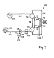
- a first embodiment of the invention is shown in which a carrier web successively passes a Lack Committeeswerk and two electron gun. From a development 100 from the carrier web 101 is fed to a Lack Committeeswerk 102.
- the carrier web 101 may be, for example, a web made of plastic, textile, fleece, fabric, metal, etc.
- the web width typically ranges between 20 cm (labels) and a few meters, while the thickness of the carrier web can be between 6 ⁇ m and several millimeters.
- the paint application unit 102 may comprise, for example, a scoop 103, a scoop roller 104, a coating roller 105 and a counterpressure roller 106.
- a lacquer layer is applied to the carrier web 101.
- the painted web then passes through a web dryer 107, which extracts the solvent from the applied paint layer.
- the web dryer 107 may be configured, for example, as a convection dryer or IR dryer.
- the carrier web 101 is then introduced into an irradiation unit 109.
- a first electron beam generator 110 and a second electron beam generator 111 are arranged, the dose rate of which can be regulated independently of one another.
- Each electron beam generator 110, 111 comprises at least one electron exit window.
- the electron beam generators 110, 111 may either be arranged at some distance from the rollers as shown in FIG. Alternatively, the electron gun may also be located directly above the rollers.
- the electron beam generators 110, 111 there is a high vacuum suitable for generating electrons.
- the electron beam generators 110, 111 are connected via pipelines 112, 113 to a pump device 114.
- the pump device 114 may be disposed inside or outside the irradiation unit 109.
- In the irradiation zone is preferably an inert gas such as nitrogen, to prevent termination of the radical reaction by the atmospheric oxygen.
- the irradiation unit 109 further comprises a high-voltage generator 115, which provides the first electron beam generator 110 and the second electron beam generator 111 with the acceleration voltage (or current) required to accelerate the electrons.
- the acceleration voltage is typically in the range between 25 kV and 300 kV.
- the carrier web 101 provided with a lacquer layer is successively moved past the first electron beam generator 110 and the second electron gun 111, where the carrier web with the lacquer layer thereon is in each case irradiated by electrons.
- the irradiation with electrons causes cross-linking of the radiation-curing lacquer, resulting in a hard, chemical-resistant and abrasion-resistant, high-gloss lacquer film.
- the printed web 101 is led out of the irradiation unit 109 via an exit roller 116 and fed to a winding 117.
- the arrangement shown in Fig. 1 can also be used to produce frosted surfaces.
- a low acceleration voltage in the first electron beam generator 110 only the top region of the application layer facing the emitter is hardened, while the underlying region of the application layer still remains free-flowing.
- the cross-linking of the upper area leads to a shrinkage, which leads to a rough and thus matted surface.
- the second electron gun 111 cures with a higher accelerating voltage, so that the entire coating layer is cured throughout.
- a hard, matt, scratch-resistant surface can be produced without the use of matting agents.
- Electron beam curing systems are used primarily in label printing and packaging printing Application, since the advantages of the rapid further processing and the low heat load of the carrier webs are used before the stamping process.
- the irradiation unit 109 has a shield 118 arranged around the electron beam generators 110, 111, which absorbs the released X-radiation and thus prevents the release of X-rays.
- the shield 118 is made of lead or steel or a lead-steel construction having a thickness in the range of millimeters or centimeters.
- the entrance roller 108 and the exit roller 116, through which the printed web is introduced into and out of the irradiation unit 109, are made of steel or lead. In particular, it is prescribed that the air gaps between the entry or exit rollers 108, 116 and the shield 118 are such that the X-radiation can no longer escape after repeated refraction.
- the radiation-curing lacquer applied to the carrier web 101 is hardened by two electron beam generators 110, 111 arranged in series.
- the coating layer is exposed to a radiation dose, which results as the sum of the radiation doses generated by the individual electron beam generators 110, 111.
- the evacuation of the electron beam generators 110, 111 can take place by means of a single pump device 114.
- a single high-voltage generator 115 suffices.
- a common shielding 118 is provided for protection against high-energy radiation.
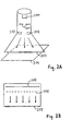
- FIGS. 2A to 2C show various embodiments of electron beam generators.
- the electron gun shown in Fig. 2A comprises a hot cathode 200 and an anode 201. Between the hot cathode 200 and the anode 201, an acceleration voltage of about 25 kV to 300 kV is applied, which accelerates the leaked from the hot cathode 200 electrons. Subsequently, the electron beam is expanded by means of deflection magnets 202. The electrons penetrate the electron exit window 203 and irradiate the carrier web 204 covered with the layer to be hardened.
- FIG. 2B shows an alternative embodiment of an electron beam generator, in which the hot cathode is designed as an elongate wire 205.
- the electrons are accelerated by means of the anode 206 and then penetrate the electron exit window 207.
- FIG. 2C shows another embodiment of an electron gun comprising a plurality of cathode wires 208.
- the electrons are accelerated by the anode 209. After penetrating the electron exit window 210, the accelerated electrons strike the carrier web 211.
- the electron gun shown in Fig. 2C is particularly suitable for use in electron beam curing because of the high electron dose rate.
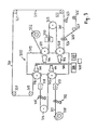
- FIG. 3 shows a web-fed printing press according to the invention with four applicator units which are arranged around a central irradiation unit 300.
- the central irradiation unit 300 comprises four electron guns 301 to 304.
- the electron guns 301 to 304 are connected via pipelines 305 to a common pumping device 306 which evacuates the connected electron guns and thus generates the operating vacuum required to accelerate the electrons.
- the irradiation unit 300 comprises a common high voltage source 307.
- the irradiation unit 300 is equipped with a control unit 308 for controlling the dose rate of the electron guns, the dose rate of the electron guns 301 to 304 can be controlled separately.
- the irradiation unit 300 is surrounded by a shield 309 made of lead or steel or a lead-steel construction.
- a carrier web 311 is fed to a printing unit 312, which applies a first ink layer to the carrier web 311.
- the carrier web 311 is guided by means of a guide roller 313 in the irradiation unit 300, where the first Ink layer cured by the electron gun 301 and then led out of the irradiation unit 300 again.
- the carrier web is then fed to a second printing unit 315 which applies a second ink layer to the carrier web 311.
- a deflection roller 316 the printed carrier web 311 is guided through the irradiation unit 300, wherein the second ink layer is cured by the electron gun 302.
- the web dryers 317, 318 remove the solvent from the applied ink layer and can be designed, for example, as a convection dryer or IR dryer.
- the carrier web 311 is guided over a plurality of rollers 319 to 322 to an adhesive applicator 323, which applies an adhesive layer to the carrier web 311.
- a plastic film web 325 is laminated onto the adhesive-coated carrier web 311, which is fed to the laminating unit 324 from a unwind 326 via a deflecting roller 327.
- the carrier web 311 with the laminated plastic film web 325 is guided through the irradiation unit 300.
- the electron beam generator 303 irradiates the web with electrons and thus hardens the adhesive layer located between the carrier web 311 and the plastic film web 325.
- the web is then fed to another applicator 330, which, for example, applies a protective layer of plastic to the printed and laminated web.
- the applicator 330 may be, for example, an extruder with a molding tool, a curtain coater, a spray nozzle, an anilox roller, a blade, etc. When using curtain coaters, several layers can be applied simultaneously.
- the coated web is passed by a deflection roller 331 at the electron beam generator 304, wherein the protective layer is cured or crosslinked by electron irradiation. After electron irradiation, the carrier web is fed to a winding 332.
- an associated electron beam generator within the irradiation unit 300 is assigned to each of the four application units.
- the electron gun are arranged in several levels one above the other, which allows a space-saving design of the order irradiation system. In particular, so the available room height can be better utilized.
- the application irradiation system shown in FIG. 3 may comprise any other application units instead of the applicators shown, wherein the support web is in each case supplied to one or more associated electron guns in the central irradiation unit after passing through a commissioned work.
- a job irradiation system of the type shown in Fig. 3 can be used to realize a four-color web press.
- printing units for flexographic printing, screen printing, gravure printing and offset printing can be used.
- the printing unit comprises a scoop 400 in which liquid printing ink 401 is located.
- the ink is picked up by a scoop roller 402, which applies the ink to an anilox roller 403 rotating immediately above it.
- a doctor blade 404 By means of a doctor blade 404, the excess ink is doctored off the anilox roller 403.
- the pressure roller 405 Above the anilox roller 403, the pressure roller 405 is arranged, which generates the actual printed image with the help of a kauklischees 406.
- the anilox roller 403 serves to uniformly apply the ink to the rubber plate 406.
- the printing unit comprises a counter-pressure roller 407, the carrier web 408 to the pressure roller 405 presses. When the carrier web 408 is moved between the platen 405 and the platen roller 407, the ink is transferred.
- Fig. 5 shows an embodiment of the invention in which a carrier web is printed on both sides in four-color printing.
- the printing press comprises a first irradiation unit 500 with four electron guns 501 to 504, which are connected to a first vacuum system with a first pump device 505. Furthermore, the printing press comprises a second irradiation unit 506 with four electron guns 507 to 510, which are connected to a second vacuum system with a second pump device 511.
- a carrier web 512 is successively guided alternately through the first irradiation unit 500 and the second irradiation unit 506 from a development 513.
- the printing units 514 to 517 four different ink layers are applied to the underside of the carrier web 512.
- the carrier web 512 is guided by means of one of the deflection rollers 518 to 521 through the first irradiation unit 500, in which the ink layers are cured by the electron beam generators 501 to 504. Accordingly, the printing inking units 522 to 525 sequentially apply four different ink layers to the upper surface of the carrier web 512.
- the carrier web is guided via one of the deflecting rollers 526 to 529 through the second irradiation unit 506, in which the ink layers are hardened by the electron beam generators 507 to 510.
- the carrier web printed on both sides in four-color printing is then fed to a winding 530.
- the carrier web can also be guided via entry and exit gaps through the shielding of the irradiation unit.
- a carrier web 600 is fed from a unwind 601 from a printing unit 602, which applies an ink layer to the carrier web 600.
- a spatially delimited irradiation unit 603 is provided which is surrounded by a shield 604.
- the irradiation unit 603 four electron guns 605-608 are arranged, which are connected via pipes 609 to a vacuum pump 610.
- the printed carrier web passes via an entrance slit 611 into the irradiation unit 603 and is successively irradiated by the two electron beam generators 605 and 606.
- the dose rate of a radiator indicates the irradiated dose per unit of time.
- the irradiation dose available for curing the ink layer is composed of the contributions from the two electron guns 605 and 606.
- a substantial increase in the radiation dose can be achieved. This makes it possible to harden even relatively slowly reacting application layers reliably.
- a radiation dose sufficient to cure the applied layers can also be provided at higher web speeds.
- the carrier web 600 leaves the irradiation unit 603 and passes via deflecting rollers 613 to a stamping unit 614.
- the carrier web 600 is guided to a varnish application unit 615, which applies a varnish layer to the carrier web 600.
- the carrier web 600 is guided via an entrance slit 616 into the irradiation unit 603 and irradiated successively therefrom by the two electron beam generators 607 and 608, the total irradiation dose being composed of the contributions of the two electron guns 607 and 608.
- the carrier web 600 is led out of the irradiation unit 603 on the opposite side via the exit slit 617.
- the carrier web can pass through additional processing stations after leaving the irradiation unit and before passing through the next job unit.
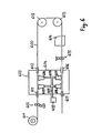
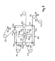
- Fig. 7 shows a further embodiment of the invention.
- a compact irradiation unit 700 around four applicators 701, 702, 703 and 704 are arranged.
- the irradiation unit 700 is formed as a spatially delimited, separate structural unit and surrounded by a shield 705.
- the irradiation unit 700 comprises four electron guns 706, 707, 708 and 709. To generate the required operating vacuum, the four electron guns 706-709 are connected to a common vacuum system 710 which is connected to a vacuum pump 711.
- a carrier web 713 is guided to the first coater 701, where a first application layer is applied.
- the carrier web 713 passes through a deflection roller 714 and an entrance slit 715 into the irradiation unit 700, where it is irradiated by the first electron gun 706, and is subsequently guided via an exit slit 716 and a deflecting roller 717 to the second applicator 702.
- the carrier web 713 is guided by means of a deflection roller 718 through the irradiation unit 700 in order to harden the second application layer by means of the second electron beam generator 707.
- the carrier web 713 Via a guide roller 719, the carrier web 713 reaches the third applicator 703, which applies a third application layer, and from there via an entrance slit 720 to the third electron gun 708, which cures the third application layer.
- the carrier web 713 is led out of the irradiation unit 700 and passes via a further guide roller 722 to the fourth applicator unit 704, which applies a further application layer to the carrier web 713.
- the coated carrier web is then passed through the irradiation unit 700 again via an entrance slit 723, wherein the newly applied application layer is cured by the fourth electron gun 709.
- Via a deflecting roller 724 the carrier web 713 passes out of the irradiation unit 700 and to the winding 725.
- the first electron gun is designed for curing a near-surface region of the first application layer and the second electron gun for curing the first application layer. In this way, even without the use of matting a hard, frosted, scratch-resistant surface can be generated.
- the application irradiation system comprises a third application unit for applying a third application layer to the carrier web as well as one arranged within the irradiation unit the third electron gun, wherein the web guiding device is adapted to supply the carrier web successively to the first applicator, the first electron gun, the second applicator, the second electron gun, the third applicator, the third electron gun.
- the third electron gun for electron beam curing of one or more previously applied application layers is designed.
- the commissioned works are arranged one above the other in at least two levels. This allows a space-saving arrangement of commissioned works.
- the height of the hall or the space in which the order irradiation system is constructed can be better utilized in comparison with the known stator construction.
- each applicator unit is assigned at least one electron beam generator arranged at an approximately corresponding height within the irradiation unit. In this way, the distances between a commissioned work and an associated electron gun can be kept low.
- a plurality of electron beam generators are arranged one above the other within the irradiation unit.
- each electron gun has at least one electron exit window.
- An electron exit window should be sufficiently permeable to accelerated electrons.
- an electron exit window should be sufficiently stable in order to be able to withstand the pressure difference between ambient pressure and vacuum.
- the application irradiation system comprises at least one control unit for controlling the dose rate of the electron beam generator arranged in the irradiation unit, wherein the dose rate of the electron beam generator is individually controllable.
- the dose rate of an electron beam generator can be adapted to the requirements of the respective application layers.
- the application irradiation system comprises a high-voltage generator for generating the acceleration voltage for the electron beam generators arranged in the irradiation unit.
- the high voltage generator is a relatively expensive component. Since only a single high-voltage generator is required to supply the electron beam generators arranged in the irradiation unit, the overall costs remain low.
- the carrier web consists of a succession of plates or sheets or beakers guided successively through the application irradiation system.
- the carrier web need not necessarily be a continuous carrier web.
- the web guiding apparatus may also be adapted to pass individual sheets, sheets or cups through the applicator irradiation system to sequentially apply different coating layers to the plates, sheets or cups.
- the web guiding device comprises a roller system for guiding the carrier web.
- the printing press is a printing machine for at least one of the following printing methods: flexographic printing, gravure printing, screen printing, offset printing.
- Electron beam curing ink systems provide hard, chemical and abrasion resistant, high gloss ink film. If a newly applied ink layer is fixed prior to the application of further ink layers by means of electron beam curing, then smearing or bleeding of the printing inks from the different commissioned works can be prevented. Regardless of the consistency of the printing ink, a high-quality printed image is created.
- the printing machine is designed for single-sided printing of the carrier web. According to an alternative embodiment, the printing machine is designed for double-sided printing of the carrier web.
- the printing press comprises two printing units arranged around the irradiation unit for realizing a two-color print.
- the printing press comprises a laminating unit and at least one printing unit, which are arranged around the irradiation unit.
- a printing machine of this embodiment may be used to print on a paper or board web and then laminated with a plastic film.
- the printing machine is intended for use in label printing or in packaging printing or in furniture film finishing.
Landscapes
- Health & Medical Sciences (AREA)
- General Health & Medical Sciences (AREA)
- Toxicology (AREA)
- Engineering & Computer Science (AREA)
- Physics & Mathematics (AREA)
- Plasma & Fusion (AREA)
- Electromagnetism (AREA)
- Mechanical Engineering (AREA)
- Coating Apparatus (AREA)
- Application Of Or Painting With Fluid Materials (AREA)
- Paper (AREA)
- Heating, Cooling, Or Curing Plastics Or The Like In General (AREA)
- Supply, Installation And Extraction Of Printed Sheets Or Plates (AREA)
Applications Claiming Priority (2)
| Application Number | Priority Date | Filing Date | Title |
|---|---|---|---|
| DE102006041257 | 2006-09-02 | ||
| DE102006057966A DE102006057966B4 (de) | 2006-09-02 | 2006-12-08 | Auftrags-Bestrahlungs-System für die Elektronenstrahlhärtung |
Publications (2)
| Publication Number | Publication Date |
|---|---|
| EP1908528A2 true EP1908528A2 (fr) | 2008-04-09 |
| EP1908528A3 EP1908528A3 (fr) | 2008-05-14 |
Family
ID=38740455
Family Applications (1)
| Application Number | Title | Priority Date | Filing Date |
|---|---|---|---|
| EP07017108A Withdrawn EP1908528A3 (fr) | 2006-09-02 | 2007-08-31 | Séchoir central pour le durcissement par faisceau d'électrons |
Country Status (3)
| Country | Link |
|---|---|
| US (1) | US7737423B2 (fr) |
| EP (1) | EP1908528A3 (fr) |
| DE (1) | DE102006057966B4 (fr) |
Cited By (1)
| Publication number | Priority date | Publication date | Assignee | Title |
|---|---|---|---|---|
| WO2014029381A3 (fr) * | 2012-08-24 | 2014-05-08 | Mankiewicz Gebr. & Co. Gmbh & Co. Kg | Encres pour impression à jet d'encre durcissables par faisceau électronique et leur utilisation dans des procédés d'impression à jet d'encre |
Families Citing this family (4)
| Publication number | Priority date | Publication date | Assignee | Title |
|---|---|---|---|---|
| DE102009013143B3 (de) * | 2009-03-13 | 2010-09-16 | Daimler Ag | Vorrichtung zum Härten einer Beschichtung |
| DE102018130287A1 (de) * | 2018-11-29 | 2020-06-04 | Koenig & Bauer Ag | Rotationsdruckmaschine mit mindestens einem Druckwerk zum Bedrucken von Substraten |
| CN113798134B (zh) * | 2020-06-17 | 2022-10-04 | 四川智研科技有限公司 | Eb双面辐照系统 |
| WO2024086323A1 (fr) * | 2022-10-21 | 2024-04-25 | Fermi Research Alliance, Llc | Véhicule à irradiateur blindé |
Family Cites Families (12)
| Publication number | Priority date | Publication date | Assignee | Title |
|---|---|---|---|---|
| GB1272133A (en) | 1969-09-23 | 1972-04-26 | British Iron Steel Research | Coating metal |
| US3924022A (en) | 1974-02-22 | 1975-12-02 | Gen Electric | Method of applying an organic coating onto an inorganic coated steel sheet for a magnetic laminate application |
| AU504068B2 (en) | 1976-06-11 | 1979-10-04 | Nippon Steel Corporation | Steel coated with two-layered polymeric product |
| US4246297A (en) | 1978-09-06 | 1981-01-20 | Energy Sciences Inc. | Process and apparatus for the curing of coatings on sensitive substrates by electron irradiation |
| US4385239A (en) * | 1981-04-20 | 1983-05-24 | Kennecott Corporation | Inerting chamber for electron curing of resin coated webs |
| EP0228671A1 (fr) | 1985-12-23 | 1987-07-15 | General Electric Company | Procédé pour la fabrication d'un substrat revêtu, à caractéristiques de surface spécifiques |
| US4642244A (en) * | 1986-03-03 | 1987-02-10 | Energy Sciences Inc. | Method of and apparatus for electron beam curing coated, porous and other web structures |
| US5634402A (en) * | 1995-10-12 | 1997-06-03 | Research, Incorporated | Coating heater system |
| AU778181B2 (en) * | 1999-10-12 | 2004-11-18 | Toyo Ink Manufacturing Co. Ltd. | Method and apparatus for irradiating active energy ray |
| US6468595B1 (en) | 2001-02-13 | 2002-10-22 | Sigma Technologies International, Inc. | Vaccum deposition of cationic polymer systems |
| DE20117364U1 (de) | 2001-10-26 | 2002-02-14 | KUNZ Holding GmbH & Co. KG, 72669 Unterensingen | Vorrichtung zur Sterilisationsbehandlung von flächigem Versandgut |
| WO2006047866A1 (fr) | 2004-11-01 | 2006-05-11 | Uview Ultraviolet Systems Inc. | Appareil et procede de durcissement de materiaux revetant une surface |
-
2006
- 2006-12-08 DE DE102006057966A patent/DE102006057966B4/de not_active Expired - Fee Related
-
2007
- 2007-08-30 US US11/847,929 patent/US7737423B2/en active Active
- 2007-08-31 EP EP07017108A patent/EP1908528A3/fr not_active Withdrawn
Cited By (2)
| Publication number | Priority date | Publication date | Assignee | Title |
|---|---|---|---|---|
| WO2014029381A3 (fr) * | 2012-08-24 | 2014-05-08 | Mankiewicz Gebr. & Co. Gmbh & Co. Kg | Encres pour impression à jet d'encre durcissables par faisceau électronique et leur utilisation dans des procédés d'impression à jet d'encre |
| US9458339B2 (en) | 2012-08-24 | 2016-10-04 | Mankiewicz Gebr. & Co. Gmbh & Co. Kg | Electron beam-curable inkjet inks and use thereof in inkjet printing methods |
Also Published As
| Publication number | Publication date |
|---|---|
| DE102006057966B4 (de) | 2008-08-28 |
| US20080087845A1 (en) | 2008-04-17 |
| US7737423B2 (en) | 2010-06-15 |
| EP1908528A3 (fr) | 2008-05-14 |
| DE102006057966A1 (de) | 2008-03-13 |
Similar Documents
| Publication | Publication Date | Title |
|---|---|---|
| DE69505640T2 (de) | Methode und verfahren zum aufbringen von durch bestrahlung härtbare druckfarben in einem flexografischen drucksystem | |
| EP2418019B1 (fr) | Procédé de matification partielle de couches de laque UV | |
| EP1967284A2 (fr) | Procédé et dispositif de renforcement de rayonnement UV de revêtements de substrat | |
| EP0655030A1 (fr) | Procede et dispositif d'humidification d'une bande de materiau en mouvement imprimee puis thermiquement sechee. | |
| DE2906978C3 (de) | Verfahren und Vorrichtung zur kontinuierlichen Herstellung eines Schichtmaterials mit reduziertem Oberflächenglanz | |
| EP1908528A2 (fr) | Séchoir central pour le durcissement par faisceau d'électrons | |
| EP1313617B1 (fr) | Procede et dispositif pour le couchage de produits imprimes | |
| EP2428359B1 (fr) | Dispositif d'impression et procédé d'impression de structures plates | |
| EP2576220A1 (fr) | Procédé et dispositif de production d'une couche structurée | |
| DE102006048523A1 (de) | Überdruckbare Prägebeschichtung | |
| DE10057642A1 (de) | Verfahren und Einrichtung zum Erzeugen unterschiedlicher Glanzgrade auf Bedruckstoffen in Druckmaschinen | |
| EP3887164B1 (fr) | Unité de séchage pour sécher des substrats imprimés | |
| EP1878987A2 (fr) | Dispositif de séchage destiné au traitement d'une surface de matière d'impression dans une machine de traitement | |
| DE102006057969A1 (de) | Zentraltrockner für mehrere Auftragswerke | |
| DE10057641A1 (de) | Verfahren und Einrichtung zum Erzeugen von Spot-Lackierungen auf Bedruckstoffen in großformatigen Druckmaschinen | |
| DE102006004144B4 (de) | Vorrichtung und Verfahren zum Beschichten von Platten | |
| EP3917780B1 (fr) | Procédé et machine d'impression respectivement pour l'impression d'un support d'impression métallique | |
| DE10106385A1 (de) | Foliendruckverfahren und Vorrichtung hierzu | |
| DE102009051174B4 (de) | Verfahren und Vorrichtung für eine Veredelung eines Druckerzeugnisses mittels maschinellen Auftrags von Pulver | |
| DE102018130285B4 (de) | Rotationsdruckmaschine mit mindestens einem Druckwerk zum Bedrucken von Substraten | |
| DE102018130279B4 (de) | Bogendruckmaschine mit mindestens einem Druckwerk zum Bedrucken von Druckbogen | |
| EP1503899A2 (fr) | Dispositif pour imprimer des feuilles metalliques et procede correspondant | |
| DE102018130284B4 (de) | Rotationsdruckmaschine mit mindestens einem Druckwerk zum Bedrucken von Substraten | |
| EP4112307A1 (fr) | Dispositif de durcissement d'un fluide durcissable aux uv sur un support imprimé doté d'un émetteur | |
| WO2008116483A1 (fr) | Dispositif et procédé d'appliquer sur un objet un élément décoratif adhérant sur un film |
Legal Events
| Date | Code | Title | Description |
|---|---|---|---|
| PUAI | Public reference made under article 153(3) epc to a published international application that has entered the european phase |
Free format text: ORIGINAL CODE: 0009012 |
|
| AK | Designated contracting states |
Kind code of ref document: A2 Designated state(s): AT BE BG CH CY CZ DE DK EE ES FI FR GB GR HU IE IS IT LI LT LU LV MC MT NL PL PT RO SE SI SK TR |
|
| AX | Request for extension of the european patent |
Extension state: AL BA HR MK RS |
|
| PUAL | Search report despatched |
Free format text: ORIGINAL CODE: 0009013 |
|
| AK | Designated contracting states |
Kind code of ref document: A3 Designated state(s): AT BE BG CH CY CZ DE DK EE ES FI FR GB GR HU IE IS IT LI LT LU LV MC MT NL PL PT RO SE SI SK TR |
|
| AX | Request for extension of the european patent |
Extension state: AL BA HR MK RS |
|
| AKX | Designation fees paid | ||
| STAA | Information on the status of an ep patent application or granted ep patent |
Free format text: STATUS: THE APPLICATION IS DEEMED TO BE WITHDRAWN |
|
| 18D | Application deemed to be withdrawn |
Effective date: 20081115 |
|
| REG | Reference to a national code |
Ref country code: DE Ref legal event code: 8566 |