EP1908489B1 - Système de thérapie pep vibratoire avec nébuliseur d'aérosol médicamenteux - Google Patents
Système de thérapie pep vibratoire avec nébuliseur d'aérosol médicamenteux Download PDFInfo
- Publication number
- EP1908489B1 EP1908489B1 EP07253894.5A EP07253894A EP1908489B1 EP 1908489 B1 EP1908489 B1 EP 1908489B1 EP 07253894 A EP07253894 A EP 07253894A EP 1908489 B1 EP1908489 B1 EP 1908489B1
- Authority
- EP
- European Patent Office
- Prior art keywords
- air
- expiratory
- therapy device
- pressure therapy
- oscillatory
- Prior art date
- Legal status (The legal status is an assumption and is not a legal conclusion. Google has not performed a legal analysis and makes no representation as to the accuracy of the status listed.)
- Active
Links
Images


Classifications
-
- A—HUMAN NECESSITIES
- A61—MEDICAL OR VETERINARY SCIENCE; HYGIENE
- A61M—DEVICES FOR INTRODUCING MEDIA INTO, OR ONTO, THE BODY; DEVICES FOR TRANSDUCING BODY MEDIA OR FOR TAKING MEDIA FROM THE BODY; DEVICES FOR PRODUCING OR ENDING SLEEP OR STUPOR
- A61M16/00—Devices for influencing the respiratory system of patients by gas treatment, e.g. ventilators; Tracheal tubes
- A61M16/08—Bellows; Connecting tubes ; Water traps; Patient circuits
-
- A—HUMAN NECESSITIES
- A61—MEDICAL OR VETERINARY SCIENCE; HYGIENE
- A61M—DEVICES FOR INTRODUCING MEDIA INTO, OR ONTO, THE BODY; DEVICES FOR TRANSDUCING BODY MEDIA OR FOR TAKING MEDIA FROM THE BODY; DEVICES FOR PRODUCING OR ENDING SLEEP OR STUPOR
- A61M15/00—Inhalators
- A61M15/0001—Details of inhalators; Constructional features thereof
- A61M15/0013—Details of inhalators; Constructional features thereof with inhalation check valves
- A61M15/0016—Details of inhalators; Constructional features thereof with inhalation check valves located downstream of the dispenser, i.e. traversed by the product
-
- A—HUMAN NECESSITIES
- A61—MEDICAL OR VETERINARY SCIENCE; HYGIENE
- A61M—DEVICES FOR INTRODUCING MEDIA INTO, OR ONTO, THE BODY; DEVICES FOR TRANSDUCING BODY MEDIA OR FOR TAKING MEDIA FROM THE BODY; DEVICES FOR PRODUCING OR ENDING SLEEP OR STUPOR
- A61M16/00—Devices for influencing the respiratory system of patients by gas treatment, e.g. ventilators; Tracheal tubes
- A61M16/0003—Accessories therefor, e.g. sensors, vibrators, negative pressure
- A61M16/0006—Accessories therefor, e.g. sensors, vibrators, negative pressure with means for creating vibrations in patients' airways
-
- A—HUMAN NECESSITIES
- A61—MEDICAL OR VETERINARY SCIENCE; HYGIENE
- A61M—DEVICES FOR INTRODUCING MEDIA INTO, OR ONTO, THE BODY; DEVICES FOR TRANSDUCING BODY MEDIA OR FOR TAKING MEDIA FROM THE BODY; DEVICES FOR PRODUCING OR ENDING SLEEP OR STUPOR
- A61M16/00—Devices for influencing the respiratory system of patients by gas treatment, e.g. ventilators; Tracheal tubes
- A61M16/20—Valves specially adapted to medical respiratory devices
- A61M16/208—Non-controlled one-way valves, e.g. exhalation, check, pop-off non-rebreathing valves
- A61M16/209—Relief valves
-
- A—HUMAN NECESSITIES
- A61—MEDICAL OR VETERINARY SCIENCE; HYGIENE
- A61M—DEVICES FOR INTRODUCING MEDIA INTO, OR ONTO, THE BODY; DEVICES FOR TRANSDUCING BODY MEDIA OR FOR TAKING MEDIA FROM THE BODY; DEVICES FOR PRODUCING OR ENDING SLEEP OR STUPOR
- A61M11/00—Sprayers or atomisers specially adapted for therapeutic purposes
- A61M11/06—Sprayers or atomisers specially adapted for therapeutic purposes of the injector type
-
- A—HUMAN NECESSITIES
- A61—MEDICAL OR VETERINARY SCIENCE; HYGIENE
- A61M—DEVICES FOR INTRODUCING MEDIA INTO, OR ONTO, THE BODY; DEVICES FOR TRANSDUCING BODY MEDIA OR FOR TAKING MEDIA FROM THE BODY; DEVICES FOR PRODUCING OR ENDING SLEEP OR STUPOR
- A61M15/00—Inhalators
- A61M15/0086—Inhalation chambers
-
- A—HUMAN NECESSITIES
- A61—MEDICAL OR VETERINARY SCIENCE; HYGIENE
- A61M—DEVICES FOR INTRODUCING MEDIA INTO, OR ONTO, THE BODY; DEVICES FOR TRANSDUCING BODY MEDIA OR FOR TAKING MEDIA FROM THE BODY; DEVICES FOR PRODUCING OR ENDING SLEEP OR STUPOR
- A61M16/00—Devices for influencing the respiratory system of patients by gas treatment, e.g. ventilators; Tracheal tubes
- A61M16/08—Bellows; Connecting tubes ; Water traps; Patient circuits
- A61M16/0816—Joints or connectors
-
- A—HUMAN NECESSITIES
- A61—MEDICAL OR VETERINARY SCIENCE; HYGIENE
- A61M—DEVICES FOR INTRODUCING MEDIA INTO, OR ONTO, THE BODY; DEVICES FOR TRANSDUCING BODY MEDIA OR FOR TAKING MEDIA FROM THE BODY; DEVICES FOR PRODUCING OR ENDING SLEEP OR STUPOR
- A61M16/00—Devices for influencing the respiratory system of patients by gas treatment, e.g. ventilators; Tracheal tubes
- A61M16/20—Valves specially adapted to medical respiratory devices
- A61M16/201—Controlled valves
- A61M16/202—Controlled valves electrically actuated
- A61M16/203—Proportional
- A61M16/205—Proportional used for exhalation control
-
- Y—GENERAL TAGGING OF NEW TECHNOLOGICAL DEVELOPMENTS; GENERAL TAGGING OF CROSS-SECTIONAL TECHNOLOGIES SPANNING OVER SEVERAL SECTIONS OF THE IPC; TECHNICAL SUBJECTS COVERED BY FORMER USPC CROSS-REFERENCE ART COLLECTIONS [XRACs] AND DIGESTS
- Y10—TECHNICAL SUBJECTS COVERED BY FORMER USPC
- Y10S—TECHNICAL SUBJECTS COVERED BY FORMER USPC CROSS-REFERENCE ART COLLECTIONS [XRACs] AND DIGESTS
- Y10S137/00—Fluid handling
- Y10S137/908—Respirator control
Definitions
- This invention relates to the field of respiratory therapy, and, more particularly, to a single patient use positive oscillatory expiratory pressure respiratory therapy device adapted for use with a medicated aerosol drug delivery system to administer positive expiratory pressure therapy (PEP).
- PEP positive expiratory pressure therapy
- PEP therapy a patient exhales against a resistance to generate expiratory pressure at a substantially constant rate of flow.
- Prescribed expiratory pressures are generally in the range of 10 - 20 cm of H 2 O, although other pressure ranges and pressures can be used, with a preferred flow rate of between 10 - 25 liters per minute.
- EP1464357 discloses a multi-use, hand-held, single patient oscillatory positive expiratory pressure respiratory therapy device which is easily assembled and disassembled for cleaning, and which is not position dependent during therapy, but operable through a wide range of device orientation.
- EP1435251 discloses an oscillatory positive expiratory pressure respiratory therapy device which may be incorporated into the expiratory limb of a ventilator circuit.
- US6412481 discloses an attachment for use with a nebulizer for delivery of aerosol medication to respiratory airways of a user which has an elongated conduit provided with a one-way valve for admitting ambient air on one of its ends and a mouthpiece on its opposite end.
- US2003/209247 discloses a hand-held breathing device for use by patients having respiratory problems and which creates a sealed backpressure in the airways of the patient by creating resistance to exhalation.
- the present invention is directed to overcoming one or more of the problems or disadvantages associated with the relevant technology.
- the present invention is embodied in a positive oscillatory expiratory air pressure respiratory therapy device which includes a medicated aerosol nebulizer for the selective administration of medicated oscillatory PEP therapy.
- the present invention provides an oscillatory positive expiratory pressure therapy device according to Claim 1.
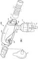
- an oscillatory positive expiratory pressure (PEP) respiratory therapy device 1000 for applying oscillatory positive expiratory air pressure therapy to a patient to which medicated aerosolized drugs are administered by means of a small volume nebulizer 5.
- PEP oscillatory positive expiratory pressure
- the oscillatory PEP device 1000 is coupled in fluid communication to the nebulizer 5 which functions to supply aerosolized medicine and/or humidified gas to the patient and may be used by the patient with a standard 22mm removable mouthpiece 3 or a 22mm standard mask 2.
- Oxygen and/or other gases to be supplied to the patient are coupled to the nebulizer 5 through a tubing 6 connected at one end to a suitable fitting 4 on the base of the nebulizer 5, and at another end to the desired gas source (not shown). If desired, as determined by the clinician, medication can be added to the nebulizer 5 for administration to the patient.
- the nebulizer 5 is coupled to the oscillatory PEP device 1000 through a nebulizer input port 202 on the underside of the PEP device 1000 so that the desired gases and medicine are supplied to the patient, preferably at a rate between about 5 to about 7 liters per minute.
- the patient inhales deeply through a patient coupling port 201 to which, for convenience of illustration, the removable mouth piece 3 is connected to enable the patient to inhale at a rate and to an extent as determined by the clinician.
- Inspiratory air enters the PEP device 1000 through an inspiratory air port 204.
- reservoir tubing 7 may be attached to the inlet port 204.
- a one-way valve 225 is positioned in the inlet air chamber 206 of the PEP device downstream of the inspiratory air port 204 and the nebulizer input port 202 so that inspiratory air may freely enter the device through the valve 225, but expiratory air from the patient is blocked from being expelled through the inspiratory air port 204 or back into the nebulizer 5.
- Expiratory air is passed from the patient through the mouthpiece 3 and out through the patient coupling port 201 into the oscillatory PEP device 1000.
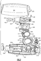
- the expiratory air passes through the patient coupling port 201 into and through an air-flow tube 200 to an expiratory-air-driven oscillatory rocker assembly 400 contained within a two part housing 300.
- the expiratory-air-driven oscillatory rocker assembly 400 creates an oscillatory positive expiratory air pressure (PEP) which is applied to the patient during exhalation.
- PEP oscillatory positive expiratory air pressure
- the expiratory-air-driven oscillatory rocker assembly 400 comprises two portions, a rocker portion 440 and a rocker support or platform portion 480 which act together in creating the oscillatory PEP therapy. It is preferable that the patient maintain exhalation for about 3 to about 4 seconds.
- a rotatable frequency control dial 350 is carried in a horizontal position about a discharge opening 203 of the air-flow tube 200, the conduit which receives the expiratory air from a patient which is passed through the patient coupling port 201.
- the air-flow tube 200 is carried by a lower housing portion 302, and supports the expiratory-air-driven oscillatory rocker assembly 400.
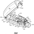
- the expiratory-air-driven oscillatory rocker portion 440 is best illustrated in the exploded view of Fig. 2 and Figs. 7 , 8 and 10 .
- the rocker support portion 480 which functions in cooperation with the rocker portion 440 to produce an oscillatory expiratory air flow and pressure, is also illustrated in the exploded view of Fig. 2 , and in more detail in Figs. 7 , 8 and 10 .
- the expiratory-air-driven oscillatory rocker portion 440 and the rocker support portion 480 when assembled together, form the rocker assembly 400.
- the rocker assembly 400 is supported on the air-flow tube 200 which has at one end the inspiratory air port 204 through which inspiratory air is received by the patient by means of the one-way valve 225, and at another end a discharge opening 203 through which expiratory air from the patient is passed to the rocker assembly 400 to produce the oscillatory expiratory air flow and pressure.
- the air-flow tube discharge opening 203 is formed on a top flat planar surface portion 205 of the air-flow tube 200 and the expiratory air passed there through is applied to the oscillatory rocker assembly 400 for creating the oscillatory PEP therapy for the patient.
- the air thereafter exits from the device 1000 through an exit opening 304 formed by a spacing between the upper and lower portions 301 and 302, respectively, of the housing 300 at an end opposite to the patient coupling port 201.
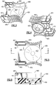
- the rocker portion 440 is balanced for pivotal movement about pivot pins 441 on spaced pivot supports 481 formed on a platform 485 of the rocker support portion 480.
- the pivot pins 441 form a pivot axis transverse to the plane of motion of the rocker portion 440 and lie in a plane above and extending transverse to the longitudinal axis of the platform 485 upon which the rocker portion 440 is supported.
- the pivot pins 441 engage a pair of locking guides 482 carried by the platform 485, one of which is positioned adjacent each of the pivot supports 481 to maintain the pivot pins 441 in their proper position on the pivot supports 481 as illustrated. In this manner the rocker portion 440 is pivotal relative to the rocker support portion 481 regardless of the orientation of the device 1000, allowing the device 1000 to function regardless of its orientation in use.
- a balance pad 442 and balancing cylinder 443 are formed at one end of the rocker arm 445 to counterbalance the weight of a cone-shaped air-flow closure member 447 and a pin 448 formed of a magnetically attractable material, such as stainless steel, both of which are carried at the opposite end of the rocker arm 445.
- Pin 448 is carried at one distal end of the rocker arm 445 between a plurality of gripping fingers 446 which encircle the pin 448 to hold the pin 448 in a position to be exposed to a magnetic field of a disc-shaped magnet 488 carried on the adjacent end of the air-flow tube 200 in a magnet holder 490.
- the disc-shaped magnet 488 and the pin 448 function to control or set the frequency of the PEP therapy oscillations and the expiratory air pressure required from the patient for this respiratory therapy.
- the cone-shaped air-flow closure member or air-flow closure cone 447 is sized and positioned on the rocker arm 445 to be periodically inserted into a tapered bell-shaped or trumpet-shaped air-discharge outlet 487 formed in the platform 485 to create a non-linear expiratory air discharge opening or outlet to create the oscillatory PEP when expiratory air is discharged through the air-flow tube discharge opening 203.
- the interior of the air-discharge outlet 487 has a non-linear taper or bell-shaped interior to form the non-linear air discharge outlet for creating the oscillatory PEP therapy in response to the pivotal movement of the air-flow closure cone 447 in to and out therefrom. In this manner the discharge outlet 487 is periodically closed and re-opened in response to the patients expiratory air discharge allowing the oscillatory PEP therapy treatment.
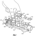
- the oscillatory rocker assembly 400 is secured onto the air-flow tube 200 and positioned within the housing 300 by means of a cowling 489 which extends downwardly from beneath the platform 485 encircling the exterior of the air-discharge outlet 487 to encircle and engage onto the outwardly extending circular outer sidewalls 287 of the air-flow tube discharge opening 203 as best illustrated in Figs. 4 and 7 .
- a pair of side walls 486 of the platform 485, the bottoms of which rest on the planar surface 205 of the air-flow tube 200, are formed with a ridged finger-engaging surface to facilitate the removal and repositioning of the rocker support portion 480 onto the air-flow tube 200 for cleaning the device 1000 as necessary.
- Sidewalls 486 extend vertically outward from the planar surface 205 of the air-flow tube 200 and are spaced apart a distance sufficient to receive the rocker arm 445 there between. In this manner the rocker arm 445 is protected between the sidewalls 486 when the upper and lower housing portions, 301 and 302, respectively, are separated for cleaning. This positioning protects the rocker assembly 400 from being inadvertently improperly grasped by a user or clinician when disassembling the device 1000 for cleaning, as the user's attention is directed to the ribbed or ridged finger-engaging surface of the side walls 486 which are intended to be grasped when the rocker assembly 400 is to be removed.
- a tang 384 extends downwardly from the interior of the upper housing portion 301, passing through an opening 444 formed in the rocker arm 445, to engage the upper surface 205 of the platform 485 to retain these components in the proper position regardless of the orientation of the device 1000 when in use.
- the upper and lower housing portions, 301 and 302, respectively, are formed as two separable portions to facilitate access into the interior of the device for cleaning.
- the upper housing portion 301 is formed with a pair of tabs 303 at each end designed to engage complementary recesses 306 formed in the lower housing portion 302 to maintain the two portions of the housing 300 engaged unless it is desired to open the housing 300 for access to the interior thereof.
- the sides of the upper housing 301 are compressed towards each other to facilitate release of the tabs 303 from the engaging recesses 306.
- a securing tab 305 extends outwardly from one end of the upper housing portion 301 in a position to engage a complementary recess 307 formed in the upper housing portion 301 adjacent to the patient coupling port 201 to facilitate securing the two housing portions together.
- the joinder of the securing tab 305 into the complementary recess 307 creates an outer diameter of a size for receiving the distal end of a standard mouthpiece 3 or mask 2 to prevent the inadvertent separation of the housing portions 301 and 302 when such components have been installed on the device 1000 when in use.
- the magnetically attractable pin 441 is positioned on the rocker arm 445 within the magnetic field of the disc magnet 488.
- the disc magnet 488 is carried in a holder 490 which is slidably positionable in a vertical direction along a pair of vertically extending guides 210 which extend upwardly from the planar surface 205 of the air-flow tube 200 adjacent to the patient coupling port 201 in accordance with the rotational position of the frequency control dial 350. In this manner the desired frequency and/or expiratory pressure can be readily set or controlled by the user in accordance with the clinician's instructions.
- the disc magnet 488 is carried in the holder 490 in a receiver pocket 491, and has a plurality of gripping or centering fingers 492 for retaining the magnet 488 in the circular-shaped receiver pocket 491.
- the receiver pocket 491 is formed at one end of the holder 490 and is movable in a vertical direction along the guides 210.
- the bottom of the holder is formed with a plurality of stops or feet 494 spaced from the bottom of the receiver pocket 491 for engaging therebetween a lip portion 395 of a cam 396 formed on the rotatable frequency control dial 350 carried in a horizontal position about the discharge opening 203 of the air-flow tube 200.
- the disc magnet 488 can be selectively positioned by the device user in operative proximity to the steel pin 448 to control or set the oscillatory frequency and/or expiratory air pressure desired for administering the oscillatory PEP therapy in accordance with the instructions of the clinician.
- the rotatable frequency control dial 350 and the cam 396 formed thereon are positioned concentrically about the sidewalls 287 of the air-flow tube discharge opening 203 by a plurality of guides 351.
- the inner diameter of the rotatable frequency control dial 350 is sized such that the dial 350 is freely rotatable while the guides 351 maintain the dial concentric with the sidewalls 287.
- the cam 396 is positioned such that the lip portion 395 thereof engages the magnet holder 490 between the bottom of the disc magnet receiver 491 and the stops or feet 494 so that the holder 490 is raised or lowered in accordance with the rotational position of the frequency control dial 350.
- a plurality of indicia 310 spaced along the frequency control dial 350 can be used to readily relocate the proper positioning.
- a series of detents 352 are utilized to prevent the inadvertent rotation of the dial 350.
- a collar 510 supported from beneath the platform 485 encircles the upper portion of the sidewalls 287 of the air-flow tube discharge opening 203 and includes a projection 512 which sequentially engages the detents 352 to prevent inadvertent rotation of the frequency control dial 350.
- a recess 514 is engaged by a tab 414 extending downwardly from the bottom of platform 485 to hold collar 510 in the desired position.
- a patient discharges expiratory air through the patient coupling port 201 of the air-flow tube 200 which passes through the air-flow tube discharge opening 203 to the oscillatory rocker assembly 400 and then out of the device 1000 through the exit space 304 between the two housing portions 301 and 302. Accordingly, the expiratory air pressure is applied against the cone-shaped closure 447 of the rocker 445 which forms a closure of the non-linear discharge opening or orifice 487.
- the pressure of the patient's expiratory air will raise the cone-shaped closure 447, causing the rocker portion 440 to pivot about the pivot pins 441 against the force of the magnetic field between the disc magnet 488 carried on the pivotal rocker support portion 480 and the steel pin 448 carried on the rocker assembly 400.
- the constant taper of the conical shape of the cone-shaped closure 447 in combination with the bell-shaped or trumpet-shaped non-linear taper discharge opening 487 forms a non-linear discharge orifice which increases in effective discharge area thereby decreasing the air pressure applied against the cone-shaped closure 447 and reducing the upward acceleration of the rocker arm 445.
Landscapes
- Health & Medical Sciences (AREA)
- Pulmonology (AREA)
- Engineering & Computer Science (AREA)
- Life Sciences & Earth Sciences (AREA)
- Anesthesiology (AREA)
- Biomedical Technology (AREA)
- Heart & Thoracic Surgery (AREA)
- Hematology (AREA)
- Animal Behavior & Ethology (AREA)
- General Health & Medical Sciences (AREA)
- Public Health (AREA)
- Veterinary Medicine (AREA)
- Emergency Medicine (AREA)
- Bioinformatics & Cheminformatics (AREA)
- Percussion Or Vibration Massage (AREA)
- Massaging Devices (AREA)
Claims (19)
- Dispositif de thérapie à pression expiratoire positive oscillante (1000) comprenant :un tube d'écoulement d'air (200) ayant une trajectoire de mouvement d'écoulement d'air à partir d'une ouverture d'entrée (201) pour qu'un utilisateur recevant la thérapie respiratoire reçoive l'air expiratoire qui y passe, en passant par une ouverture de sortie (203) pour décharger l'air expiratoire qui est passé par ladite ouverture d'entrée (201) ;ledit tube d'écoulement d'air (200) comprenant un moyen de fermeture sensible à l'air expiratoire (400) positionné dans ladite trajectoire de mouvement d'écoulement d'air et pouvant être actionné entre une position ouverte et une position fermée en réponse à la pression d'air expiratoire qui y est passé ;ledit moyen de fermeture sensible à l'air expiratoire (400) comprenant une sortie de décharge non linéaire normalement fermée (487) qui est ouverte en réponse à la présence d'une pression prédéterminée d'air expiratoire qui est passé par ladite trajectoire de mouvement d'écoulement d'air, et qui se ferme en réponse à une vitesse prédéterminée de réduction de pression d'air par ladite sortie de décharge non linéaire (487) ;ledit moyen de fermeture sensible à l'air expiratoire comprenant en outre un élément de fermeture (447) mobile en réponse à l'air expiratoire dans ladite trajectoire de mouvement d'écoulement d'air entre une position fermée bloquant l'écoulement d'air expiratoire et une position ouverte permettant l'écoulement d'air expiratoire dans ladite trajectoire de mouvement d'écoulement d'air ;le tube d'écoulement d'air (200) ayant, au niveau d'une extrémité opposée à l'ouverture d'entrée (201), un orifice d'entrée d'air inspiratoire (204) par lequel l'air inspiratoire est aspiré dans le dispositif pour être reçu par le patient ;dans lequel le dispositif comprend en outre un moyen de couplage de nébuliseur (202) raccordé au tube d'écoulement d'air (200) pour raccorder un nébuliseur en communication de fluide avec une trajectoire d'écoulement d'air inspiratoire de l'orifice d'entrée d'air inspiratoire (204) à un utilisateur ;dans lequel le dispositif comprend une valve à une voie (225) positionnée en aval de l'orifice d'entrée d'air inspiratoire (204) et du moyen de couplage de nébuliseur (202) de sorte que l'air inspiratoire peut librement entrer dans le dispositif par la valve à une voie (225), mais l'air expiratoire provenant du patient ne peut pas être expulsé par l'orifice d'entrée d'air inspiratoire (204) ou par le moyen de couplage de nébuliseur (202).
- Dispositif de thérapie à pression expiratoire positive oscillante selon la revendication 1, dans lequel ledit élément de fermeture (447) est en forme de cône et ladite sortie de décharge non linéaire (487) est en forme de cloche.
- Dispositif de thérapie à pression expiratoire positive oscillante selon la revendication 1, dans lequel ledit élément de fermeture (447) est en forme de cône et ladite sortie de décharge non linéaire (487) est en forme de trompette.
- Dispositif de thérapie à pression expiratoire positive oscillante selon la revendication 1, dans lequel ledit élément de fermeture (447) est en forme de cône et ladite sortie de décharge non linéaire (487) est un orifice de décharge progressivement rétréci non linéaire.
- Dispositif de thérapie à pression expiratoire positive oscillante selon la revendication 1, comprenant en outre un moyen d'application de champ de force magnétique (488) pour générer une force de sollicitation effectuant l'ouverture et la fermeture de ladite sortie de décharge non linéaire (487).
- Dispositif de thérapie à pression expiratoire positive oscillante selon la revendication 5, comprenant en outre un moyen pour ajuster la grandeur du moyen d'application de champ de force magnétique.
- Dispositif de thérapie à pression expiratoire positive oscillante selon la revendication 6, dans lequel ledit moyen pour ajuster la grandeur du moyen d'application de champ magnétique comprend un cadran de réglage de fréquence (350) rotatif.
- Dispositif de thérapie à pression expiratoire positive oscillante selon la revendication 7, dans lequel ledit cadran de réglage de fréquence (350) rotatif est horizontalement disposé par rapport à ladite sortie de décharge non linéaire (487).
- Dispositif de thérapie à pression expiratoire positive oscillante selon la revendication 8, dans lequel ledit cadran de réglage de fréquence (350) rotatif comprend en outre une pluralité de détentes (352) circonférentiellement espacées pour empêcher sa libre rotation.
- Dispositif de thérapie à pression expiratoire positive oscillante selon la revendication 8, dans lequel ladite sortie de décharge non linéaire (487) est en forme de cloche.
- Dispositif de thérapie à pression expiratoire positive oscillante selon la revendication 1, dans lequel ledit moyen de fermeture sensible à l'air expiratoire (400) comprenant une sortie de décharge non linéaire normalement fermée (487) qui est ouverte en réponse à la présence d'une pression prédéterminée d'air expiratoire qui est passé dans ladite trajectoire de mouvement d'écoulement d'air, et qui se ferme en réponse à une vitesse prédéterminée de réduction de pression d'air par ladite sortie de décharge non linéaire (487) et comprend un ensemble de balancier oscillant comprenant une partie de balancier (440) supportée de manière pivotante sur une partie de support de balancier (480).
- Dispositif de thérapie à pression expiratoire positive oscillante selon la revendication 11, dans lequel ladite partie de balancier (440) comprend un élément de fermeture en forme de cône (447) porté sur ladite partie de balancier (440) pour le mouvement pivotant dans et hors de ladite sortie de décharge non linéaire (487) et ladite partie de support de balancier (480) comprend un orifice de décharge non linéaire curviligne progressivement rétréci qui est fermé en réponse au mouvement dudit élément de fermeture en forme de cône.
- Dispositif de thérapie à pression expiratoire positive oscillante selon la revendication 12, dans lequel ladite sortie de décharge non linéaire (487) est en forme de cloche.
- Dispositif de thérapie à pression expiratoire positive oscillante selon la revendication 12, dans lequel ladite sortie de décharge non linéaire (487) est en forme de trompette.
- Dispositif de thérapie à pression expiratoire positive oscillante selon la revendication 1, comprenant en outre un nébuliseur (5) raccordé de manière opérationnelle audit moyen de couplage de nébuliseur (202).
- Dispositif de thérapie à pression expiratoire positive oscillante selon la revendication 15, dans lequel ledit nébuliseur (5) comprend un moyen pour fournir un médicament audit nébuliseur (5).
- Dispositif de thérapie à pression expiratoire positive oscillante selon la revendication 1, comprenant en outre un embout buccal (3) supporté par ledit tube d'écoulement d'air (200) à travers lequel l'air inspiratoire et l'air expiratoire passent jusqu'à un utilisateur.
- Dispositif de thérapie à pression expiratoire positive oscillante selon la revendication 1, comprenant en outre un masque facial (2) supporté par ledit tube d'écoulement d'air (200) à travers lequel l'air inspiratoire et l'air expiratoire passent jusqu'à un utilisateur.
- Dispositif de thérapie à pression expiratoire positive oscillante selon la revendication 1, comprenant en outre un tube de réservoir (7) couplé audit orifice d'entrée d'air inspiratoire (204) dudit tube d'écoulement d'air.
Applications Claiming Priority (1)
| Application Number | Priority Date | Filing Date | Title |
|---|---|---|---|
| US11/538,329 US8225785B2 (en) | 2006-10-03 | 2006-10-03 | Vibratory PEP therapy system with medicated aerosol nebulizer |
Publications (2)
| Publication Number | Publication Date |
|---|---|
| EP1908489A1 EP1908489A1 (fr) | 2008-04-09 |
| EP1908489B1 true EP1908489B1 (fr) | 2017-01-18 |
Family
ID=38895819
Family Applications (1)
| Application Number | Title | Priority Date | Filing Date |
|---|---|---|---|
| EP07253894.5A Active EP1908489B1 (fr) | 2006-10-03 | 2007-10-02 | Système de thérapie pep vibratoire avec nébuliseur d'aérosol médicamenteux |
Country Status (4)
| Country | Link |
|---|---|
| US (2) | US8225785B2 (fr) |
| EP (1) | EP1908489B1 (fr) |
| JP (2) | JP2008086768A (fr) |
| AU (1) | AU2007219313B2 (fr) |
Families Citing this family (68)
| Publication number | Priority date | Publication date | Assignee | Title |
|---|---|---|---|---|
| US10610228B2 (en) | 2004-12-08 | 2020-04-07 | Theravent, Inc. | Passive nasal peep devices |
| US8225785B2 (en) * | 2006-10-03 | 2012-07-24 | Smiths Medical Asd, Inc. | Vibratory PEP therapy system with medicated aerosol nebulizer |
| US7779841B2 (en) * | 2006-11-13 | 2010-08-24 | Carefusion 2200, Inc. | Respiratory therapy device and method |
| US9566397B2 (en) * | 2007-05-15 | 2017-02-14 | Joseph Dee Faram | Small-volume nebulizers and methods of use thereof |
| US9849254B2 (en) * | 2007-05-15 | 2017-12-26 | Caddo Medical Technologies Llc | Pre-filled, small-volume nebulizer |
| WO2009099995A1 (fr) * | 2008-02-01 | 2009-08-13 | Ventus Medical, Inc. | Interface de cpap et dispositifs de secours |
| US8251876B2 (en) | 2008-04-22 | 2012-08-28 | Hill-Rom Services, Inc. | Breathing exercise apparatus |
| US8539951B1 (en) | 2008-05-27 | 2013-09-24 | Trudell Medical International | Oscillating positive respiratory pressure device |
| US8327849B2 (en) | 2008-10-28 | 2012-12-11 | Trudell Medical International | Oscillating positive expiratory pressure device |
| DE102008054431B3 (de) * | 2008-12-09 | 2010-06-17 | Pari Pharma Gmbh | Aerosoltherapievorrichtung |
| US9149589B2 (en) | 2009-02-23 | 2015-10-06 | Trudell Medical International | Method and device for performing orientation dependent oscillating positive expiratory pressure therapy |
| US8485179B1 (en) | 2009-02-23 | 2013-07-16 | Trudell Medical International | Oscillating positive expiratory pressure device |
| ES2628077T3 (es) * | 2009-02-27 | 2017-08-01 | Pari GmbH Spezialisten für effektive Inhalation | Dispositivo de inhalación de aerosol |
| US11452838B2 (en) | 2011-04-28 | 2022-09-27 | Michael J. Rusher | Positive expiratory pressure devices with flutter valve |
| US20120272956A1 (en) * | 2011-04-28 | 2012-11-01 | Rusher Michael J | Airway pressure control devices |
| WO2012168780A2 (fr) | 2011-06-06 | 2012-12-13 | Trudell Medical International | Dispositif à pression expiratoire positive oscillante |
| US9180271B2 (en) | 2012-03-05 | 2015-11-10 | Hill-Rom Services Pte. Ltd. | Respiratory therapy device having standard and oscillatory PEP with nebulizer |
| US9808592B2 (en) | 2012-07-13 | 2017-11-07 | Muffin Incorporated | Nebulizing catheter for bronchial therapy |
| CA2832687A1 (fr) * | 2012-11-26 | 2014-05-26 | Beng Leong Toh | Systemes generateurs d'impulsions pour dispositif de therapie |
| US9517315B2 (en) | 2012-11-30 | 2016-12-13 | Trudell Medical International | Oscillating positive expiratory pressure device |
| US9700688B2 (en) | 2013-03-15 | 2017-07-11 | Trudell Medical International | Delivery device and kit, and method of use |
| WO2014140774A1 (fr) * | 2013-03-15 | 2014-09-18 | Trudell Medical International | Dispositif d'administration et kit, et procédé d'utilisation |
| USD753284S1 (en) * | 2013-06-12 | 2016-04-05 | M. LaQuisha Burks | Expiratory muscle strength trainer adapter |
| GB201310824D0 (en) * | 2013-06-18 | 2013-07-31 | Smiths Medical Int Ltd | Respiratory therapy apparatus and methods |
| GB201310826D0 (en) * | 2013-06-18 | 2013-07-31 | Smiths Medical Int Ltd | Respiratory therapy apparatus and methods |
| EP3019137B1 (fr) | 2013-07-12 | 2019-02-06 | Trudell Medical International | Dispositif de simulation de toux soufflée ("huff cough") |
| WO2015006639A1 (fr) | 2013-07-12 | 2015-01-15 | SILVA, John, H. | Pièce buccale pour inhalateur |
| US9849257B2 (en) | 2013-08-22 | 2017-12-26 | Trudell Medical International | Oscillating positive respiratory pressure device |
| GB201316223D0 (en) * | 2013-09-12 | 2013-10-30 | Smiths Medical Int Ltd | Respiratory therapy apparatus and methods |
| US10363383B2 (en) | 2014-02-07 | 2019-07-30 | Trudell Medical International | Pressure indicator for an oscillating positive expiratory pressure device |
| USD796664S1 (en) * | 2014-05-13 | 2017-09-05 | Khalil A Hill | Visual flow indicator rotating nebulizer |
| USD748242S1 (en) * | 2014-07-11 | 2016-01-26 | H. Stuart Campbell | Inhaler mouthpiece |
| US10434277B2 (en) | 2014-08-14 | 2019-10-08 | Rbt Medical Products Llc | Positive expiratory pressure device and methods of using same |
| US10561805B2 (en) | 2014-10-10 | 2020-02-18 | Ablynx N.V. | Methods of treating RSV infections |
| EP3204095B8 (fr) * | 2014-10-10 | 2019-07-10 | Ablynx N.V. | Dispositif d'inhalation pour utilisation dans une thérapie par aérosol de maladies respiratoires |
| GB201420127D0 (en) * | 2014-11-12 | 2014-12-24 | Smiths Medical Int Ltd | Respiratory therapy apparatus |
| TWD169846S (zh) * | 2014-12-12 | 2015-08-11 | 李文欽 | 噴霧器(二) |
| US10004872B1 (en) | 2015-03-06 | 2018-06-26 | D R Burton Healthcare, Llc | Positive expiratory pressure device having an oscillating valve |
| AU2016243801B2 (en) | 2015-04-02 | 2020-05-21 | Hill-Rom Services Pte. Ltd. | Manifold for respiratory device |
| USD768285S1 (en) * | 2015-06-04 | 2016-10-04 | George A Reed | Respiratory apparatus |
| EP3328473B1 (fr) | 2015-07-30 | 2022-06-01 | Trudell Medical International | Dispositif combiné d'entraînement pour muscles respiratoires et de pression expiratoire positive oscillante |
| USD779071S1 (en) | 2015-08-14 | 2017-02-14 | Christopher D. Warner, III | Positive expiratory pressure device |
| USD778429S1 (en) | 2015-09-02 | 2017-02-07 | Trudell Medical International | Respiratory treatment device |
| USD780906S1 (en) | 2015-09-02 | 2017-03-07 | Trudell Medical International | Respiratory treatment device |
| EP3368115B1 (fr) * | 2015-10-30 | 2020-06-24 | Koninklijke Philips N.V. | Entraînement respiratoire, dispositif de surveillance et/ou d'assistance |
| ES2855373T3 (es) | 2015-12-04 | 2021-09-23 | Trudell Medical Int | Dispositivo de simulación de tos por espiración forzada |
| FR3046937B1 (fr) * | 2016-01-25 | 2019-08-09 | Universite Grenoble Alpes | Dispositif d'acclimatation a l'altitude et procede de fonctionnement de ce dispositif. |
| USD861855S1 (en) * | 2016-05-04 | 2019-10-01 | R. Cegla Gmbh & Co. Kg | Inhaler |
| USD855173S1 (en) * | 2016-05-04 | 2019-07-30 | R. Cegla Gmbh & Co. Kg | Inhaler |
| CA3059532C (fr) | 2017-05-03 | 2024-10-01 | Trudell Medical International Inc. | Therapie par pression expiratoire positive oscillante combinee et dispositif de simulation de toux soufflee ("huff cough") |
| USD874006S1 (en) * | 2017-06-15 | 2020-01-28 | Aerofit.Dk Aps | Respiratory exercise device |
| US10342935B2 (en) | 2017-11-21 | 2019-07-09 | Caddo Medical Technologies Llc | Internal nebulizer seal and method of use |
| US10953278B2 (en) | 2018-02-02 | 2021-03-23 | Trudell Medical International | Oscillating positive expiratory pressure device |
| EP3524303A1 (fr) | 2018-02-12 | 2019-08-14 | Vortran Medical Technology 1, Inc. | Appareil respiratoire à percussion à faible débit et traitement associé |
| US10258758B1 (en) | 2018-04-20 | 2019-04-16 | Caddo Medical Technologies Llc | Flow controlled valve for a small-volume nebulizer |
| WO2019222463A1 (fr) * | 2018-05-16 | 2019-11-21 | Massachusetts Institute Of Technology | Procédés et appareil pour échantillonnage et distribution passifs, proportionnels et sans vanne d'un gaz |
| USD926308S1 (en) * | 2018-05-30 | 2021-07-27 | Medipines Corporation | Breathing tube for a respiratory gas exchange monitor |
| US11464925B2 (en) | 2018-06-04 | 2022-10-11 | Trudell Medical International | Positive air pressure therapy device, kit and methods for the use and assembly thereof |
| GB201810197D0 (en) | 2018-06-21 | 2018-08-08 | Smiths Medical International Ltd | Respiratory therapy devices and assemblies |
| US10780318B1 (en) * | 2019-04-18 | 2020-09-22 | Firas Kasem Ghazzawi | Breathing device with exhale and inhale valve to create resistance |
| WO2020225817A1 (fr) * | 2019-05-08 | 2020-11-12 | Respinova Ltd. | Système d'administration de thérapies inhalées |
| US11813397B2 (en) * | 2019-06-11 | 2023-11-14 | Justin Rowley | Nebulizer with flutter valve |
| CN112023364A (zh) * | 2020-07-31 | 2020-12-04 | 南通市第二人民医院 | 一种呼吸康复用可调式的吸气训练装置 |
| CN114832190A (zh) * | 2021-02-02 | 2022-08-02 | 上海增欣机电科技股份有限公司 | 一种便携式正压排痰呼吸训练器 |
| TWI779663B (zh) * | 2021-06-15 | 2022-10-01 | 岩成科技事業股份有限公司 | 震盪式吐氣正壓裝置 |
| USD1076056S1 (en) * | 2021-08-02 | 2025-05-20 | Mercury Enterprises, Inc. | Oscillating positive expiratory pressure device |
| CN113599643B (zh) * | 2021-08-05 | 2024-01-02 | 宁波蓝柏医疗器械有限公司 | 一种呼吸双用振动排痰器 |
| CN113648619A (zh) * | 2021-09-26 | 2021-11-16 | 重庆上品益生电子商务有限公司 | 呼吸训练器 |
Family Cites Families (13)
| Publication number | Priority date | Publication date | Assignee | Title |
|---|---|---|---|---|
| US3826255A (en) * | 1972-06-22 | 1974-07-30 | Hudson Oxygen Therapy Sales Co | Intermittent positive pressure breathing manifold |
| US4188946A (en) * | 1977-10-07 | 1980-02-19 | Rayburn Robert L | Controllable partial rebreathing anesthesia circuit and respiratory assist device |
| US5086765A (en) * | 1990-08-29 | 1992-02-11 | Walter Levine | Nebulizer |
| US5598839A (en) * | 1994-04-20 | 1997-02-04 | Diemolding Corporation | Positive expiratory pressure device |
| WO2000027455A1 (fr) * | 1998-11-06 | 2000-05-18 | Salter Labs | Embout buccal et accessoires pour nebuliseur |
| US6776159B2 (en) | 1999-11-24 | 2004-08-17 | Dhd Healthcare Corporation | Positive expiratory pressure device with bypass |
| US6581598B1 (en) | 1999-11-24 | 2003-06-24 | Dhd Healthcare Corporation | Positive expiratory pressure device |
| US7059324B2 (en) | 1999-11-24 | 2006-06-13 | Smiths Medical Asd, Inc. | Positive expiratory pressure device with bypass |
| US6786216B2 (en) | 1999-12-23 | 2004-09-07 | O'rourke Sam | Sealed back pressure breathing device |
| US6412481B1 (en) * | 1999-12-23 | 2002-07-02 | Robert Bienvenu | Sealed backpressure attachment device for nebulizer |
| EP1272243B1 (fr) * | 2000-04-11 | 2005-10-26 | Trudell Medical International | Appareil aerosol avec une capacite de pression expiratoire positive |
| AU2005234774B2 (en) * | 2004-04-20 | 2011-01-20 | Novartis Ag | Aerosol delivery apparatus for pressure assisted breathing |
| US8225785B2 (en) * | 2006-10-03 | 2012-07-24 | Smiths Medical Asd, Inc. | Vibratory PEP therapy system with medicated aerosol nebulizer |
-
2006
- 2006-10-03 US US11/538,329 patent/US8225785B2/en active Active
-
2007
- 2007-09-26 AU AU2007219313A patent/AU2007219313B2/en not_active Ceased
- 2007-09-28 JP JP2007253803A patent/JP2008086768A/ja not_active Withdrawn
- 2007-10-02 EP EP07253894.5A patent/EP1908489B1/fr active Active
-
2012
- 2012-04-05 US US13/440,622 patent/US9205217B2/en active Active
-
2016
- 2016-07-25 JP JP2016145243A patent/JP2016195836A/ja active Pending
Non-Patent Citations (1)
| Title |
|---|
| None * |
Also Published As
| Publication number | Publication date |
|---|---|
| US20080078383A1 (en) | 2008-04-03 |
| US8225785B2 (en) | 2012-07-24 |
| US9205217B2 (en) | 2015-12-08 |
| US20120186585A1 (en) | 2012-07-26 |
| AU2007219313A1 (en) | 2008-04-17 |
| JP2008086768A (ja) | 2008-04-17 |
| JP2016195836A (ja) | 2016-11-24 |
| AU2007219313B2 (en) | 2012-11-01 |
| EP1908489A1 (fr) | 2008-04-09 |
Similar Documents
| Publication | Publication Date | Title |
|---|---|---|
| EP1908489B1 (fr) | Système de thérapie pep vibratoire avec nébuliseur d'aérosol médicamenteux | |
| EP1464357B1 (fr) | Appareil pour pression expiratoire positive | |
| JP4411165B2 (ja) | 連続高周波振動呼吸治療装置 | |
| EP1435251B1 (fr) | Dispositif de pression positive de fin d'expiration a dérivation | |
| US5027809A (en) | "Peeper" performance hand held nebuilizer attachment with adjustability of expiratory pressures and expiratory restriction | |
| EP1103287B1 (fr) | Appareil pour pression expiratoire positive | |
| JP3993894B2 (ja) | ネブライザー装置および方法 | |
| RU2448742C2 (ru) | Высокочастотное осциллирующее респираторное терапевтическое устройство | |
| US9913955B2 (en) | Oscillating positive expiratory pressure device | |
| US5522380A (en) | Metered dose medication adaptor with improved incentive spirometer | |
| WO2019070804A1 (fr) | Thérapie respiratoire | |
| US11458264B2 (en) | Valved flexible bag spacer device for a nebulizer | |
| US20240399099A1 (en) | Aerosol drug inspiratory with respiratory support capability | |
| CA2210721C (fr) | Adaptateur pour doseur de medicaments ayant un spirometre de stimulation ameliore | |
| US20240399079A1 (en) | In-line pressure balanced aerosol concentrator |
Legal Events
| Date | Code | Title | Description |
|---|---|---|---|
| PUAI | Public reference made under article 153(3) epc to a published international application that has entered the european phase |
Free format text: ORIGINAL CODE: 0009012 |
|
| AK | Designated contracting states |
Kind code of ref document: A1 Designated state(s): AT BE BG CH CY CZ DE DK EE ES FI FR GB GR HU IE IS IT LI LT LU LV MC MT NL PL PT RO SE SI SK TR |
|
| AX | Request for extension of the european patent |
Extension state: AL BA HR MK RS |
|
| 17P | Request for examination filed |
Effective date: 20080725 |
|
| 17Q | First examination report despatched |
Effective date: 20080825 |
|
| AKX | Designation fees paid |
Designated state(s): AT BE BG CH CY CZ DE DK EE ES FI FR GB GR HU IE IS IT LI LT LU LV MC MT NL PL PT RO SE SI SK TR |
|
| RIC1 | Information provided on ipc code assigned before grant |
Ipc: A61M 16/20 20060101ALI20160713BHEP Ipc: A61M 16/00 20060101ALI20160713BHEP Ipc: A61M 11/06 20060101ALN20160713BHEP Ipc: A61M 16/08 20060101AFI20160713BHEP Ipc: A61M 15/00 20060101ALI20160713BHEP |
|
| GRAP | Despatch of communication of intention to grant a patent |
Free format text: ORIGINAL CODE: EPIDOSNIGR1 |
|
| RAP1 | Party data changed (applicant data changed or rights of an application transferred) |
Owner name: SMITHS MEDICAL ASD, INC. |
|
| INTG | Intention to grant announced |
Effective date: 20160922 |
|
| GRAS | Grant fee paid |
Free format text: ORIGINAL CODE: EPIDOSNIGR3 |
|
| GRAA | (expected) grant |
Free format text: ORIGINAL CODE: 0009210 |
|
| AK | Designated contracting states |
Kind code of ref document: B1 Designated state(s): AT BE BG CH CY CZ DE DK EE ES FI FR GB GR HU IE IS IT LI LT LU LV MC MT NL PL PT RO SE SI SK TR |
|
| REG | Reference to a national code |
Ref country code: GB Ref legal event code: FG4D |
|
| REG | Reference to a national code |
Ref country code: CH Ref legal event code: EP |
|
| REG | Reference to a national code |
Ref country code: AT Ref legal event code: REF Ref document number: 862539 Country of ref document: AT Kind code of ref document: T Effective date: 20170215 |
|
| REG | Reference to a national code |
Ref country code: IE Ref legal event code: FG4D |
|
| REG | Reference to a national code |
Ref country code: DE Ref legal event code: R096 Ref document number: 602007049563 Country of ref document: DE |
|
| REG | Reference to a national code |
Ref country code: NL Ref legal event code: MP Effective date: 20170118 |
|
| REG | Reference to a national code |
Ref country code: LT Ref legal event code: MG4D |
|
| REG | Reference to a national code |
Ref country code: AT Ref legal event code: MK05 Ref document number: 862539 Country of ref document: AT Kind code of ref document: T Effective date: 20170118 |
|
| PG25 | Lapsed in a contracting state [announced via postgrant information from national office to epo] |
Ref country code: NL Free format text: LAPSE BECAUSE OF FAILURE TO SUBMIT A TRANSLATION OF THE DESCRIPTION OR TO PAY THE FEE WITHIN THE PRESCRIBED TIME-LIMIT Effective date: 20170118 |
|
| PG25 | Lapsed in a contracting state [announced via postgrant information from national office to epo] |
Ref country code: GR Free format text: LAPSE BECAUSE OF FAILURE TO SUBMIT A TRANSLATION OF THE DESCRIPTION OR TO PAY THE FEE WITHIN THE PRESCRIBED TIME-LIMIT Effective date: 20170419 Ref country code: FI Free format text: LAPSE BECAUSE OF FAILURE TO SUBMIT A TRANSLATION OF THE DESCRIPTION OR TO PAY THE FEE WITHIN THE PRESCRIBED TIME-LIMIT Effective date: 20170118 Ref country code: LT Free format text: LAPSE BECAUSE OF FAILURE TO SUBMIT A TRANSLATION OF THE DESCRIPTION OR TO PAY THE FEE WITHIN THE PRESCRIBED TIME-LIMIT Effective date: 20170118 Ref country code: IS Free format text: LAPSE BECAUSE OF FAILURE TO SUBMIT A TRANSLATION OF THE DESCRIPTION OR TO PAY THE FEE WITHIN THE PRESCRIBED TIME-LIMIT Effective date: 20170518 |
|
| PG25 | Lapsed in a contracting state [announced via postgrant information from national office to epo] |
Ref country code: PL Free format text: LAPSE BECAUSE OF FAILURE TO SUBMIT A TRANSLATION OF THE DESCRIPTION OR TO PAY THE FEE WITHIN THE PRESCRIBED TIME-LIMIT Effective date: 20170118 Ref country code: LV Free format text: LAPSE BECAUSE OF FAILURE TO SUBMIT A TRANSLATION OF THE DESCRIPTION OR TO PAY THE FEE WITHIN THE PRESCRIBED TIME-LIMIT Effective date: 20170118 Ref country code: PT Free format text: LAPSE BECAUSE OF FAILURE TO SUBMIT A TRANSLATION OF THE DESCRIPTION OR TO PAY THE FEE WITHIN THE PRESCRIBED TIME-LIMIT Effective date: 20170518 Ref country code: SE Free format text: LAPSE BECAUSE OF FAILURE TO SUBMIT A TRANSLATION OF THE DESCRIPTION OR TO PAY THE FEE WITHIN THE PRESCRIBED TIME-LIMIT Effective date: 20170118 Ref country code: BG Free format text: LAPSE BECAUSE OF FAILURE TO SUBMIT A TRANSLATION OF THE DESCRIPTION OR TO PAY THE FEE WITHIN THE PRESCRIBED TIME-LIMIT Effective date: 20170418 Ref country code: ES Free format text: LAPSE BECAUSE OF FAILURE TO SUBMIT A TRANSLATION OF THE DESCRIPTION OR TO PAY THE FEE WITHIN THE PRESCRIBED TIME-LIMIT Effective date: 20170118 Ref country code: AT Free format text: LAPSE BECAUSE OF FAILURE TO SUBMIT A TRANSLATION OF THE DESCRIPTION OR TO PAY THE FEE WITHIN THE PRESCRIBED TIME-LIMIT Effective date: 20170118 |
|
| REG | Reference to a national code |
Ref country code: FR Ref legal event code: PLFP Year of fee payment: 11 |
|
| REG | Reference to a national code |
Ref country code: DE Ref legal event code: R097 Ref document number: 602007049563 Country of ref document: DE |
|
| PG25 | Lapsed in a contracting state [announced via postgrant information from national office to epo] |
Ref country code: CZ Free format text: LAPSE BECAUSE OF FAILURE TO SUBMIT A TRANSLATION OF THE DESCRIPTION OR TO PAY THE FEE WITHIN THE PRESCRIBED TIME-LIMIT Effective date: 20170118 Ref country code: SK Free format text: LAPSE BECAUSE OF FAILURE TO SUBMIT A TRANSLATION OF THE DESCRIPTION OR TO PAY THE FEE WITHIN THE PRESCRIBED TIME-LIMIT Effective date: 20170118 Ref country code: IT Free format text: LAPSE BECAUSE OF FAILURE TO SUBMIT A TRANSLATION OF THE DESCRIPTION OR TO PAY THE FEE WITHIN THE PRESCRIBED TIME-LIMIT Effective date: 20170118 Ref country code: EE Free format text: LAPSE BECAUSE OF FAILURE TO SUBMIT A TRANSLATION OF THE DESCRIPTION OR TO PAY THE FEE WITHIN THE PRESCRIBED TIME-LIMIT Effective date: 20170118 Ref country code: RO Free format text: LAPSE BECAUSE OF FAILURE TO SUBMIT A TRANSLATION OF THE DESCRIPTION OR TO PAY THE FEE WITHIN THE PRESCRIBED TIME-LIMIT Effective date: 20170118 |
|
| PLBE | No opposition filed within time limit |
Free format text: ORIGINAL CODE: 0009261 |
|
| STAA | Information on the status of an ep patent application or granted ep patent |
Free format text: STATUS: NO OPPOSITION FILED WITHIN TIME LIMIT |
|
| PG25 | Lapsed in a contracting state [announced via postgrant information from national office to epo] |
Ref country code: DK Free format text: LAPSE BECAUSE OF FAILURE TO SUBMIT A TRANSLATION OF THE DESCRIPTION OR TO PAY THE FEE WITHIN THE PRESCRIBED TIME-LIMIT Effective date: 20170118 |
|
| 26N | No opposition filed |
Effective date: 20171019 |
|
| PG25 | Lapsed in a contracting state [announced via postgrant information from national office to epo] |
Ref country code: SI Free format text: LAPSE BECAUSE OF FAILURE TO SUBMIT A TRANSLATION OF THE DESCRIPTION OR TO PAY THE FEE WITHIN THE PRESCRIBED TIME-LIMIT Effective date: 20170118 |
|
| PG25 | Lapsed in a contracting state [announced via postgrant information from national office to epo] |
Ref country code: MC Free format text: LAPSE BECAUSE OF FAILURE TO SUBMIT A TRANSLATION OF THE DESCRIPTION OR TO PAY THE FEE WITHIN THE PRESCRIBED TIME-LIMIT Effective date: 20170118 |
|
| REG | Reference to a national code |
Ref country code: CH Ref legal event code: PL |
|
| REG | Reference to a national code |
Ref country code: IE Ref legal event code: MM4A |
|
| PG25 | Lapsed in a contracting state [announced via postgrant information from national office to epo] |
Ref country code: CH Free format text: LAPSE BECAUSE OF NON-PAYMENT OF DUE FEES Effective date: 20171031 Ref country code: LI Free format text: LAPSE BECAUSE OF NON-PAYMENT OF DUE FEES Effective date: 20171031 Ref country code: LU Free format text: LAPSE BECAUSE OF NON-PAYMENT OF DUE FEES Effective date: 20171002 |
|
| REG | Reference to a national code |
Ref country code: BE Ref legal event code: MM Effective date: 20171031 |
|
| PG25 | Lapsed in a contracting state [announced via postgrant information from national office to epo] |
Ref country code: BE Free format text: LAPSE BECAUSE OF NON-PAYMENT OF DUE FEES Effective date: 20171031 |
|
| REG | Reference to a national code |
Ref country code: FR Ref legal event code: PLFP Year of fee payment: 12 |
|
| PG25 | Lapsed in a contracting state [announced via postgrant information from national office to epo] |
Ref country code: MT Free format text: LAPSE BECAUSE OF NON-PAYMENT OF DUE FEES Effective date: 20171002 |
|
| PG25 | Lapsed in a contracting state [announced via postgrant information from national office to epo] |
Ref country code: IE Free format text: LAPSE BECAUSE OF NON-PAYMENT OF DUE FEES Effective date: 20171002 |
|
| PGFP | Annual fee paid to national office [announced via postgrant information from national office to epo] |
Ref country code: FR Payment date: 20180913 Year of fee payment: 12 |
|
| PG25 | Lapsed in a contracting state [announced via postgrant information from national office to epo] |
Ref country code: HU Free format text: LAPSE BECAUSE OF FAILURE TO SUBMIT A TRANSLATION OF THE DESCRIPTION OR TO PAY THE FEE WITHIN THE PRESCRIBED TIME-LIMIT; INVALID AB INITIO Effective date: 20071002 |
|
| PG25 | Lapsed in a contracting state [announced via postgrant information from national office to epo] |
Ref country code: CY Free format text: LAPSE BECAUSE OF NON-PAYMENT OF DUE FEES Effective date: 20170118 |
|
| PG25 | Lapsed in a contracting state [announced via postgrant information from national office to epo] |
Ref country code: TR Free format text: LAPSE BECAUSE OF FAILURE TO SUBMIT A TRANSLATION OF THE DESCRIPTION OR TO PAY THE FEE WITHIN THE PRESCRIBED TIME-LIMIT Effective date: 20170118 |
|
| PG25 | Lapsed in a contracting state [announced via postgrant information from national office to epo] |
Ref country code: FR Free format text: LAPSE BECAUSE OF NON-PAYMENT OF DUE FEES Effective date: 20191031 |
|
| P01 | Opt-out of the competence of the unified patent court (upc) registered |
Effective date: 20230419 |
|
| REG | Reference to a national code |
Ref country code: GB Ref legal event code: 732E Free format text: REGISTERED BETWEEN 20240919 AND 20240925 |
|
| REG | Reference to a national code |
Ref country code: DE Ref legal event code: R082 Ref document number: 602007049563 Country of ref document: DE Representative=s name: CHARRIER RAPP & LIEBAU PATENTANWAELTE PARTG MB, DE Ref country code: DE Ref legal event code: R081 Ref document number: 602007049563 Country of ref document: DE Owner name: ICU MEDICAL, INC., SAN CLEMENTE, US Free format text: FORMER OWNER: SMITHS MEDICAL ASD, INC., PLYMOUTH, MINN., US |
|
| PGFP | Annual fee paid to national office [announced via postgrant information from national office to epo] |
Ref country code: GB Payment date: 20250904 Year of fee payment: 19 |
|
| PGFP | Annual fee paid to national office [announced via postgrant information from national office to epo] |
Ref country code: DE Payment date: 20250902 Year of fee payment: 19 |