EP1908433B1 - Bridge framework as a dental prosthesis - Google Patents
Bridge framework as a dental prosthesis Download PDFInfo
- Publication number
- EP1908433B1 EP1908433B1 EP20070019420 EP07019420A EP1908433B1 EP 1908433 B1 EP1908433 B1 EP 1908433B1 EP 20070019420 EP20070019420 EP 20070019420 EP 07019420 A EP07019420 A EP 07019420A EP 1908433 B1 EP1908433 B1 EP 1908433B1
- Authority
- EP
- European Patent Office
- Prior art keywords
- bridge
- bridge framework
- ceramic
- primary
- male
- Prior art date
- Legal status (The legal status is an assumption and is not a legal conclusion. Google has not performed a legal analysis and makes no representation as to the accuracy of the status listed.)
- Not-in-force
Links
Images
Classifications
-
- A—HUMAN NECESSITIES
- A61—MEDICAL OR VETERINARY SCIENCE; HYGIENE
- A61C—DENTISTRY; APPARATUS OR METHODS FOR ORAL OR DENTAL HYGIENE
- A61C13/00—Dental prostheses; Making same
- A61C13/08—Artificial teeth; Making same
- A61C13/083—Porcelain or ceramic teeth
-
- A—HUMAN NECESSITIES
- A61—MEDICAL OR VETERINARY SCIENCE; HYGIENE
- A61C—DENTISTRY; APPARATUS OR METHODS FOR ORAL OR DENTAL HYGIENE
- A61C13/00—Dental prostheses; Making same
- A61C13/08—Artificial teeth; Making same
Definitions
- the invention relates to a bridge framework for a dental prosthesis in the form of a large-span bridge of a ceramic material based on zirconium dioxide, consisting of a primary part and a secondary part connected thereto, wherein the connection between the primary part and the secondary part is formed via a connecting element and the parts to be joined are designed as corresponding shaped parts in the form of a male part and a female part, and wherein the bridge frame can be placed on prepared tooth stumps. Furthermore, the invention relates to a method for producing such a bridge framework.
- the zirconia ceramic material is becoming increasingly important as a metal substitute because of its excellent mechanical properties, such as its high flexural strength and hardness, and its excellent biocompatibility. Its color and its biotechnical properties enable the production of high-quality esthetic dental components, such as crowns and bridge constructions.
- high-quality esthetic dental components such as crowns and bridge constructions.
- large-span bridge frameworks and bridge structures made of zirconia ceramic can be done so far only by means of relatively complex CAD / CAM systems. Only these are suitable to manufacture components with sufficiently large dimensions in one piece from a corresponding ceramic blank.
- blanks of a size required for the manufacture of such components are relatively expensive and are only conditionally available.
- the object of the invention is to provide a bridge framework of the type mentioned in such a way that it also withstand stronger compressive forces acting on the connection area, without prematurely failing, and that it is also suitable both in the posterior region and in the anterior region to be used. Furthermore, a method for producing such a bridge framework is to be specified by the invention.
- the solution of the first object is achieved according to the invention, that after joining the parts to be joined from a zirconium dioxide material in a bridge member an inner enclosed central region is formed with a material connection between the primary part and the secondary part, wherein the compound via a in a ceramic Brand solidifiable ceramic solder is formed.
- the bridge scaffold according to the invention also withstands elevated pressure in that punctiform stresses on the central bridge area the applied tensile and bending forces are redirected to adjacent anchoring elements, such as crowns or partial crowns. In this way, a substantial reduction of bending and shearing stresses to values that can not endanger the composite system as a whole, guaranteed.
- the bridge frameworks according to the invention are doing with the usual in dental laboratories funds available and at the same time relatively easy and inexpensive to produce.
- a favorable design is that the male has an upper end edge with the Matrizen Scheme and a lower support area with a circular groove for receiving the die.
- the corresponding boundaries of primary and secondary parts are formed as rounding in the form of flowing transitions.
- this allows optimal inflow of the adhesive through capillary forces into the regions to be joined together.
- the optimal conditions for an application of the inventively provided ceramic solder to achieve a cohesive connection are ensured.
- a load-bearing training is also created in particular by the fact that the cross-section of the lying between the bridge members connecting elements has an area size of at least 9 mm 2 .
- the entire bridge framework produced in this way be veneered in the joined state.
- the bridge framework according to the invention can thus be used without restrictions both in the anterior and in the posterior region, regardless of the size and the number of bridge elements required. In this case, there is no static restriction for the overall construction, even with a small number of remaining abutment teeth, so that can be used by only four existing abutment teeth according to the invention produced circular bridges.
- the invention provides a combination of small-span bridge elements to large-span restorations in the form of a horizontal extension as well as a vertical extension at insufficient blank height to design oversized long teeth.
- the materials used in the invention may be both sintered green material and hot isostatically pressed zirconia, so-called HIP zircon.
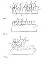
- FIG. 1 shows an initial situation for receiving a bridge framework made of ceramic on prepared tooth stumps 1 with a surrounding the tooth roots Periodontium 2 and the gingival margin 3, with areas 4, in which teeth are missing, as well as with existing natural teeth. 5
- a bridge framework provided for the supply of this situation exists according to FIGS. 2 and 3 from a primary part 6 with a connection area as a male part 7 and an associated secondary part 8 with a female part 9 as a corresponding connection area.
- crowns 10 of the bridge framework are assigned to the tooth stumps 1 and are connected to one another by bridge members 11 via integrally formed regions situated between the bridge members, so-called connecting elements 12.
- the joining region of primary part 6 and secondary part 8 to be joined is formed in a bridge member 11.
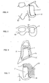
- the male part 7 as part of the bridge member 11 following the connector 12 is formed as a conical extension in the insertion direction and has rounded portions with flowing transitions.
- a stepped edge 13 for the aufndde secondary part 8 with the die 9 to form the bridge member 11 is formed in the upper region of the bridge member 11 with the male part 7 .
- the die 9 is received via a lower support area 14 with a circular groove 15 of the male part 7.
- an adhesive gap 16 between the male part 7 and the die 9 is formed, which receives the ceramic solder.
- the groove 15 offers not only one for joining enlarged surface, but at the same time gives an optimal pressure absorption.
- the joining takes place in a ceramic firing, before finally the bridge framework is ceramic-veneered as a whole.
Landscapes
- Health & Medical Sciences (AREA)
- Epidemiology (AREA)
- Oral & Maxillofacial Surgery (AREA)
- Dentistry (AREA)
- Life Sciences & Earth Sciences (AREA)
- Animal Behavior & Ethology (AREA)
- General Health & Medical Sciences (AREA)
- Public Health (AREA)
- Veterinary Medicine (AREA)
- Ceramic Engineering (AREA)
- Engineering & Computer Science (AREA)
- Chemical & Material Sciences (AREA)
- Dental Preparations (AREA)
- Ceramic Products (AREA)
Description
Die Erfindung bezieht sich auf ein Brückengerüst für einen Zahnersatz in Form einer großspannigen Brücke aus einem keramischen Werkstoff auf der Basis von Zirkondioxid, bestehend aus einem Primärteil und einem mit diesem verbundenen Sekundärteil, wobei die Verbindung zwischen dem Primärteil und dem Sekundärteil über ein verbindungselement gebildet ist und die zu verbindenden Teile als korrespondierende Formteile in Gestalt einer Patrize und einer Matrize ausgebildet sind und wobei das Brückengerüst auf präparierte zahnstümpfe aufsetzbar ist. Ferner bezieht sich die Erfindung auf ein Verfahren zur Herstellung eines solchen Brückengerüstes.The invention relates to a bridge framework for a dental prosthesis in the form of a large-span bridge of a ceramic material based on zirconium dioxide, consisting of a primary part and a secondary part connected thereto, wherein the connection between the primary part and the secondary part is formed via a connecting element and the parts to be joined are designed as corresponding shaped parts in the form of a male part and a female part, and wherein the bridge frame can be placed on prepared tooth stumps. Furthermore, the invention relates to a method for producing such a bridge framework.
Im Bereich der Dentaltechnik erlangt der keramische Werkstoff zirkondioxid aufgrund seiner hervorragenden mechanischen Eigenschaften, wie der hohen Biegefestigkeit und Härte, sowie aufgrund seiner exzellenten Biokompatibilität zunehmende Bedeutung als Metallersatz. Seine Farbe und seine biotechnischen Eigenschaften ermöglichen die Herstellung von hochwertigen ästethischen Dentalkomponenten, wie Kronen und Brückenkonstruktionen. Es besteht allerdings in der Praxis die Schwierigkeit, daß die Fertigung großspanniger Brückengerüste und Brückenkonstruktionen aus Zirkondioxid-Keramik bisher nur mittels relativ aufwendiger CAD/CAM-Anlagen erfolgen kann. Nur diese sind geeignet, Komponenten mit hinreichend großen Abmessungen in einem Stück aus einem entsprechenden Keramikrohling zu fertigen. Hinzu kommt, daß Rohlinge in einer Größe, die für die Fertigung solcher Komponenten erforderlich ist, relativ kostspielig sind und nur bedingt zur Verfügung stehen.In the field of dental technology, the zirconia ceramic material is becoming increasingly important as a metal substitute because of its excellent mechanical properties, such as its high flexural strength and hardness, and its excellent biocompatibility. Its color and its biotechnical properties enable the production of high-quality esthetic dental components, such as crowns and bridge constructions. However, in practice, there is the difficulty that the production of large-span bridge frameworks and bridge structures made of zirconia ceramic can be done so far only by means of relatively complex CAD / CAM systems. Only these are suitable to manufacture components with sufficiently large dimensions in one piece from a corresponding ceramic blank. In addition, blanks of a size required for the manufacture of such components are relatively expensive and are only conditionally available.
Es besteht daher das Bestreben, mehrgliedrige Brückengerüste aus mehreren einzelnen Komponenten zu fertigen, die jeweils zunächst einzeln aus entsprechend dimensionierten Keramikrohlingen hergestellt werden können, die eine wesentlich geringere Ausgangsgröße aufweisen müssen und deren Bearbeitung deshalb auch auf in herkömmlichen Zahntechniklaboren vorhandenen Bearbeitungseinrichtungen möglich ist. Ein derartiges Brüchengerüst ist beispielsverse aus der
Aus der
Daneben ist es bereits bekannt, bei der Verbindung von aus Keramik gefertigten Primär- und Sekundärteilen zu einem Brückengerüst das Primärteil mit einem Ansatz in Form eines sogenannten Geschiebes, beispielsweise eines Schroederzapfens, zu versehen, der über einen Steg einstöckig an das Primärteil angeformt ist und auf den das Sekundärteil im wesentlichen vertikal aufgeschoben wird.In addition, it is already known to provide the primary part with a projection in the form of a so-called attachment, such as a Schroederzapfens, when connecting ceramic primary and secondary parts to a bridge frame, which is integrally formed on a web to the primary part and on the secondary part is pushed substantially vertically.
Ferner ist in der
In diesen bekannten Fällen stellt sich das Problem, eine ausreichende Bruchfestigkeit eines so hergestellten Brückengerüstes, insbesondere bei punktförmigen Druck- und Kerbbelastungen auf den mittleren Bereich der Brücke, sicherzustellen.In these known cases, there is the problem of ensuring a sufficient breaking strength of a bridge framework produced in this way, in particular with punctiform pressure and notch loads on the middle region of the bridge.
Aufgabe der Erfindung ist es, ein Brückengerüst der eingangs genannten Art so auszubilden, daß es auch stärkeren Druckkräften, die auf den verbindungsbereich einwirken, widersteht, ohne vorzeitig zu versagen, und daß es zugleich geeignet ist, sowohl im Seitenzahnbereich als auch im Frontzahnbereich eingesetzt zu werden. Weiterhin soll durch die Erfindung ein Verfahren zur Herstellung eines solchen Brückengerüstes angegeben werden.The object of the invention is to provide a bridge framework of the type mentioned in such a way that it also withstand stronger compressive forces acting on the connection area, without prematurely failing, and that it is also suitable both in the posterior region and in the anterior region to be used. Furthermore, a method for producing such a bridge framework is to be specified by the invention.
Die Lösung der ersten Aufgabe erfolgt erfindungsgemäß dadurch, daß nach dem Zusammenfügen der miteinander zu verbindenden Teile aus einem Zirkondioxidwerkstoff in einem Brückenglied ein innenliegender umschlossener zentraler Bereich mit einer stoffschlüssigen Verbindung zwischen dem Primärteil und dem Sekundärteil gebildet ist, wobei die Verbindung über ein in einem keramischen Brand verfestigbares Keramiklot gebildet ist.The solution of the first object is achieved according to the invention, that after joining the parts to be joined from a zirconium dioxide material in a bridge member an inner enclosed central region is formed with a material connection between the primary part and the secondary part, wherein the compound via a in a ceramic Brand solidifiable ceramic solder is formed.
Durch die erfindungsgemäße Ausbildung des Brückengerüstes wird ein keramikgerechtes Design ermöglicht. Da das Fügen in einem Brückenglied über ein beim keramischen Brand der Brücke als Ganzes verfestigendes Keramiklot erfolgt und zu einer stoffschlüssigen Verbindung von Primär- und Sekundärteil miteinander führt, widersteht das Brückengerüst nach der Erfindung auch erhöhtem Druck dadurch, daß bei punktförmigen Beanspruchungen auf den mittleren Brückenbereich die einwirkenden Zug- und Biegekräfte auf benachbarte Verankerungselemente, wie Kronen oder Teilkronen, umgeleitet werden. Auf diese Weise ist eine weitgehende Reduktion von Biege- und Scherbeanspruchungen auf Werte, die das Verbundsystem als Ganzes nicht gefährden können, gewährleistet. Die Brückengerüste nach der Erfindung sind dabei mit den in zahntechnischen Laboren üblicherweise verfügbaren Mitteln und zugleich relativ einfach und preisgünstig herstellbar.The inventive construction of the bridge scaffold a ceramic design is made possible. Since the joining takes place in a bridge member via a ceramic braze solidifying the ceramic firing of the bridge as a whole and leads to a cohesive connection of primary and secondary parts with each other, the bridge framework according to the invention also withstands elevated pressure in that punctiform stresses on the central bridge area the applied tensile and bending forces are redirected to adjacent anchoring elements, such as crowns or partial crowns. In this way, a substantial reduction of bending and shearing stresses to values that can not endanger the composite system as a whole, guaranteed. The bridge frameworks according to the invention are doing with the usual in dental laboratories funds available and at the same time relatively easy and inexpensive to produce.
Eine günstige Ausbildung besteht darin, daß die Patrize eine obere Abschlußkante mit dem Matrizenbereich und einen unteren Auflagebereich mit einer zirkulären Hohlkehle zur Aufnahme der Matrize aufweist. Um eine schonende Krafteinleitung herbeizuführen und um scharfe Kanten zu vermeiden, wird zudem vorgeschlagen, daß die korrespondierenden Begrenzungen von Primär- und Sekundärteil als Abrundungen in Form von fließenden Übergängen ausgebildet sind. Dies ermöglicht zugleich ein optimales Einfließen des Klebers durch Kapillarkräfte in die miteinander zu verbindenden Bereiche. Auf diese Weise werden die optimalen Bedingungen für eine Anwendung des erfindungsgemäß vorgesehenen Keramiklotes zur Erzielung einer stoffschlüssigen Verbindung gewährleistet. Eine belastbare Ausbildung wird darüber hinaus insbesondere dadurch geschaffen, daß der Querschnitt der zwischen den Brückengliedern liegenden Verbindungselementen eine Flächengröße von wenigstens 9 mm2 aufweist.A favorable design is that the male has an upper end edge with the Matrizenbereich and a lower support area with a circular groove for receiving the die. To bring about a gentle introduction of force and to avoid sharp edges, it is also proposed that the corresponding boundaries of primary and secondary parts are formed as rounding in the form of flowing transitions. At the same time, this allows optimal inflow of the adhesive through capillary forces into the regions to be joined together. In this way, the optimal conditions for an application of the inventively provided ceramic solder to achieve a cohesive connection are ensured. A load-bearing training is also created in particular by the fact that the cross-section of the lying between the bridge members connecting elements has an area size of at least 9 mm 2 .
Weiterhin wird vorgeschlagen, daß das gesamte derart hergestellte Brückengerüst im gefügten Zustand verblendet wird. Das erfindungsgemäße Brückengerüst ist damit ohne Einschränkungen sowohl im Front- als auch im Seitenzahnbereich einsetzbar, unabhängig von der Größe und der Anzahl der erforderlichen Brückenglieder. Dabei besteht selbst bei einer geringen Anzahl von noch vorhandenen Pfeilerzähnen keine statische Einschränkung für die Gesamtkonstruktion, so daß nach dem erfindungsgemäß hergestellten zirkulären Brücken auch bei nur noch vier vorhandenen Pfeilerzähnen verwendet werden können.Furthermore, it is proposed that the entire bridge framework produced in this way be veneered in the joined state. The bridge framework according to the invention can thus be used without restrictions both in the anterior and in the posterior region, regardless of the size and the number of bridge elements required. In this case, there is no static restriction for the overall construction, even with a small number of remaining abutment teeth, so that can be used by only four existing abutment teeth according to the invention produced circular bridges.
Durch die Erfindung ist eine Kombination von kleinspannigen Brückenelementen zu großspannigen Restaurationen in Form einer horizontalen Erweiterung ebenso möglich wie eine vertikale Verlängerung bei nicht ausreichender Blankhöhe zur Gestaltung überdimensional langer Zähne. Bei den im Rahmen der Erfindung eingesetzten Werkstoffen kann es sich dabei sowohl um gesintertes Grünlingsmaterial als auch um heiß-isostatisch verpreßtes Zirkondioxid, sogenanntes HIP-Zirkon, handeln.The invention provides a combination of small-span bridge elements to large-span restorations in the form of a horizontal extension as well as a vertical extension at insufficient blank height to design oversized long teeth. The materials used in the invention may be both sintered green material and hot isostatically pressed zirconia, so-called HIP zircon.
Nachfolgend soll die Erfindung anhand von in den Zeichnungen dargestellten Ausführungsbeispielen näher erläutert werden. Es zeigen:
- Fig. 1
- eine Ausgangsposition zum Aufsetzen eines Brückengerüstes mit drei präparierten Stümpfen in einer ersten Ausführungsform,
- Fig. 2
- die Anordnung gemäß
Fig. 1 mit einem aufgesetzten Brückengerüst aus miteinander verbundenem Primärteil und Sekundärteil, - Fig. 3
- eine Prinzipdarstellung der zugeordneten zusammenzusetzenden Teile und die angedeutete Einschubbewegung der Anordnung gemäß
Fig. 1 , - Fig. 4
- einen Verbindungsbereich des Primärteils gemäß
Fig. 3 mit einer Patrize in vergrößerter vestibulärer Darstellung, - Fig. 5
- eine Draufsicht oder okklusale Ansicht der Anordnung gemäß
Fig. 4 , - Fig. 6
- eine Draufsicht in Pfeilrichtung oder approximale Ansicht auf den verbindungsbereich der Anordnung gemäß
Fig. 4 und - Fig. 7
- eine vergrößerte Schnittdarstellung des Verbindungsbereiches zwischen Primärteil und aufgesetztem Sekundärteil der Anordnung gemäß den
Figuren 2 und 3
- Fig. 1
- a starting position for placing a bridge framework with three prepared stumps in a first embodiment,
- Fig. 2
- the arrangement according to
Fig. 1 with an attached bridge framework of interconnected primary part and secondary part, - Fig. 3
- a schematic diagram of the associated zusammenzusetzenden parts and the indicated insertion movement of the arrangement according to
Fig. 1 . - Fig. 4
- a connection area of the primary part according to
Fig. 3 with a patrix in enlarged vestibular representation, - Fig. 5
- a plan view or occlusal view of the arrangement according to
Fig. 4 . - Fig. 6
- a plan view in the direction of arrow or approximal view of the connection region of the arrangement according to
Fig. 4 and - Fig. 7
- an enlarged sectional view of the connecting portion between the primary part and the attached secondary part of the arrangement according to the
FIGS. 2 and 3 with a glue gap.
Die Darstellung gemäß
Ein zur versorgung dieser Situation vorgesehenes Brückengerüst besteht gemäß den
Die Patrize 7 als Teil des Brückengliedes 11 im Anschluß an den Verbinder 12 ist als konische Erweiterung in Einschubrichtung ausgebildet und besitzt Abrundungen mit fließenden Übergängen. Im oberen Bereich des Brückengliedes 11 mit der Patrize 7 ist eine abgesetzte Abschlußkante 13 für das aufzusetzende Sekundärteil 8 mit der Matrize 9 zur Bildung des Brückengliedes 11 ausgebildet. Die Matrize 9 wird dabei über einen unteren Auflagebereich 14 mit einer zirkulären Hohlkehle 15 der Patrize 7 aufgenommen. Hierbei wird ein Klebespalt 16 zwischen der Patrize 7 und der Matrize 9 gebildet, der das Keramiklot aufnimmt. Die Hohlkehle 15 bietet dabei nicht nur eine für das Fügen vergrößerte Oberfläche, sondern ergibt zugleich eine optimale Druckaufnahme.The
Nach dem Einbringen des Keramiklotes in den Klebespalt 16 und dem Zusammenführen von Primärteil 6 und Sekundärteil 8 erfolgt das Fügen in einem keramischen Brand, bevor das Brückengerüst abschließend als Ganzes keramisch verblendet wird.After the introduction of the ceramic solder into the
Durch die Umschließung der Patrize 7 durch die Matrize 9 wird eine große Auflagefläche für die Verbindung geschaffen, die eine optimale Druckverteilung ermöglicht. Ferner ist bei der in den
Bei dem vorangehend beschriebenen Ausführungsbeispiel ist damit eine optimal formschlüssige und nach der erfolgten Verbindung durch das im keramischen Brand aushärtende Keramiklot insbesondere auch stoffschlüssige Verbindung von Primär- und Sekundärteil gegeben. Die dabei erzielbare Bruchfestigkeit in dem gefügten Brückenglied ist so hoch, daß die auf diese weise hergestellten Brückengerüste bei einer Bruchprüfung in einem Dreipunktbiegeversuch nicht an der Klebestelle, sondern im Bereich des nicht geklebten umgebenden vollmaterials versagen, wenn die Biegefestigkeit des für die Herstellung des Brückengerüstes verwendeten Zirkondioxids überschritten wird.In the embodiment described above is thus given an optimally positive and after the successful connection by the ceramic firing hardening ceramic solder in particular cohesive connection of primary and secondary parts. The thereby achievable breaking strength in the joined bridge member is so high that the bridgework produced in this way fail in a fracture test in a three-point bending test not at the splice, but in the area of the non-bonded surrounding full material, if the flexural strength of the used for the preparation of the bridge framework Zirkondioxids is exceeded.
Claims (6)
- Bridge framework for a dental prosthesis in the form of a long-span bridge made of a ceramic material based on zirconium dioxide, comprising a primary part (6) and a secondary part (8) connected thereto, wherein the connection between the primary part and the secondary part is formed by way of a connecting element (12) and the parts to be connected are configured as corresponding mouldings in the form of a male part and a female part, and wherein the bridge framework can be fitted to prepared tooth stumps, wherein, after the parts made of a zirconium dioxide material that are to be connected have been joined together in a bridge member, an internal enclosed central region with a material-bonded connection between the primary part (6) and the secondary part (8) is formed, and wherein the connection is formed by a ceramic solder which can be hardened by ceramic firing.
- Bridge framework according to claim 1, characterised in that the primary part (6) in the connecting region is formed as the female part (7) and the secondary part (8) has the associated male part (9) which can be slipped onto the female part (7) approximately vertically.
- Bridge framework according to claim 2, characterised in that the male part is formed as a conical widening in the insertion direction and has an upper border (13) with the female part region and a lower bearing region (14) with a circular channel (15) for receiving the female part (9).
- Bridge framework according to any one of claims 1 to 3, characterised in that the corresponding boundaries of the male part (7) and of the female part (9) are configured as rounded areas in the form of smooth transitions.
- Bridge framework according to any one of claims 1 to 4, characterised in that the cross-section of the connecting element (12) between the elements of the bridge has an area of at least 9 mm2.
- Bridge framework according to any one of claims 1 to 5, characterised in that the bridge framework in the joined state can be ceramically veneered.
Applications Claiming Priority (1)
| Application Number | Priority Date | Filing Date | Title |
|---|---|---|---|
| DE200610047341 DE102006047341B4 (en) | 2006-10-06 | 2006-10-06 | Bridge framework as a denture |
Publications (2)
| Publication Number | Publication Date |
|---|---|
| EP1908433A1 EP1908433A1 (en) | 2008-04-09 |
| EP1908433B1 true EP1908433B1 (en) | 2013-01-16 |
Family
ID=38957702
Family Applications (1)
| Application Number | Title | Priority Date | Filing Date |
|---|---|---|---|
| EP20070019420 Not-in-force EP1908433B1 (en) | 2006-10-06 | 2007-10-04 | Bridge framework as a dental prosthesis |
Country Status (3)
| Country | Link |
|---|---|
| EP (1) | EP1908433B1 (en) |
| DE (1) | DE102006047341B4 (en) |
| ES (1) | ES2402010T3 (en) |
Families Citing this family (4)
| Publication number | Priority date | Publication date | Assignee | Title |
|---|---|---|---|---|
| DE102009051655B3 (en) | 2009-07-14 | 2010-12-30 | Dcm Gmbh | Process for conditioning the surfaces of dental components and uses of the method |
| EP3082644B1 (en) * | 2013-12-19 | 2017-09-06 | Juvora Limited | Dental frameworks and related apparatus and methods |
| CN112386344B (en) * | 2020-10-15 | 2022-10-21 | 儒蓉(成都)医疗科技有限公司 | Elastic veneered bridge and preparation method thereof |
| DE102023133355A1 (en) | 2023-11-29 | 2025-06-05 | Maximilian Prücklmaier | Temporary tooth prosthesis for temporary and/or removable arrangement on at least two implants in a mouth area and manufacturing method of the temporary tooth prosthesis |
Family Cites Families (8)
| Publication number | Priority date | Publication date | Assignee | Title |
|---|---|---|---|---|
| US4744757A (en) * | 1985-03-20 | 1988-05-17 | Corning Glass Works | Fixed partial dentures and method of making |
| DE3930358A1 (en) | 1989-09-12 | 1991-05-08 | Dental Labor Werner Puckert | Dental bridge frame - with inter:dentate bridge portions having protective coating |
| ATE274860T1 (en) * | 1995-12-19 | 2004-09-15 | Ivoclar Vivadent Ag | METHOD FOR PRODUCING DENTAL CROWNS AND/OR DENTAL BRIDGES |
| DE19835778A1 (en) | 1998-08-07 | 2000-02-17 | Weigl Paul | Anchoring unit for a removable denture comprises a socket made of galvanically formed fine gold attached to the prosthesis structure by means of an adhesive |
| DE19853949C2 (en) * | 1998-11-23 | 2003-01-09 | Ivoclar Vivadent Ag | Ceramic tooth restoration |
| US6939136B2 (en) * | 2000-03-22 | 2005-09-06 | K L Aps | Dental bridge assembly and binding agents therefor |
| DE10248629A1 (en) | 2002-07-02 | 2004-01-22 | Degudent Gmbh | Process for producing a dental bridge framework and positive model for such |
| WO2004004595A2 (en) * | 2002-07-02 | 2004-01-15 | Degudent Gmbh | Method for the production of a dental bridge frame and positive model therefor |
-
2006
- 2006-10-06 DE DE200610047341 patent/DE102006047341B4/en not_active Expired - Fee Related
-
2007
- 2007-10-04 ES ES07019420T patent/ES2402010T3/en active Active
- 2007-10-04 EP EP20070019420 patent/EP1908433B1/en not_active Not-in-force
Also Published As
| Publication number | Publication date |
|---|---|
| DE102006047341B4 (en) | 2013-08-08 |
| ES2402010T3 (en) | 2013-04-26 |
| EP1908433A1 (en) | 2008-04-09 |
| DE102006047341A1 (en) | 2008-04-10 |
Similar Documents
| Publication | Publication Date | Title |
|---|---|---|
| EP2775955B1 (en) | Milling block, method for producing partial or total prostheses and milling block system | |
| DE102005023105B4 (en) | Process for producing a tooth replacement part and a tooth replacement part produced in this way | |
| DE102012201092B4 (en) | Dental implant system | |
| EP1881802A2 (en) | Method for production of a tooth replacement piece tooth replacement piece and corresponding component and blank | |
| EP2090263A1 (en) | Abutment with inlay for dental implants | |
| DE102009001782A1 (en) | gingivaformer | |
| EP1908433B1 (en) | Bridge framework as a dental prosthesis | |
| DE102012108153A1 (en) | Blank and process for producing a dental restoration by subtractive processing | |
| EP2114288A1 (en) | Method relating to implants, and a machine-readable medium and a computer | |
| DE10348369B4 (en) | Tooth restoration part and method for producing a tooth restoration part | |
| EP1004278B1 (en) | Ceramic dental restoration | |
| DE102008058305A1 (en) | Connecting device for fastening dental prosthesis to toothless jaw-bone of patient, has connecting elements including male parts, which extend from implants along male part axes running parallel to each other | |
| DE102016107935A1 (en) | Method for producing a real veneer and veneering and bridge obtainable by the method | |
| EP1603483B1 (en) | Method for producing a dental prosthesis and artificial tooth therefor | |
| EP2800538A1 (en) | Dental implant | |
| DE3535266A1 (en) | Dental anchorage | |
| DE19624864C2 (en) | Restoration pen | |
| DE102013207048A1 (en) | Method for producing a precision denture model for the manufacture / adaptation of a dental prosthesis | |
| DE2102564A1 (en) | Denture | |
| DE10348370B4 (en) | Tooth restoration part | |
| EP0664106A2 (en) | System for restauring damaged teeth | |
| EP3125819B1 (en) | Method for producing an artificial tooth crown, tooth crown and cover using this tooth crown | |
| EP0998882A2 (en) | Method for manufacturing dental prostheses | |
| DE20004765U1 (en) | Tertiary structure construction for the manufacture of dentures | |
| WO1998032395A1 (en) | Dental bridge |
Legal Events
| Date | Code | Title | Description |
|---|---|---|---|
| PUAI | Public reference made under article 153(3) epc to a published international application that has entered the european phase |
Free format text: ORIGINAL CODE: 0009012 |
|
| AK | Designated contracting states |
Kind code of ref document: A1 Designated state(s): AT BE BG CH CY CZ DE DK EE ES FI FR GB GR HU IE IS IT LI LT LU LV MC MT NL PL PT RO SE SI SK TR |
|
| AX | Request for extension of the european patent |
Extension state: AL BA HR MK RS |
|
| RIN1 | Information on inventor provided before grant (corrected) |
Inventor name: ZOTHNER, AURICA |
|
| 17P | Request for examination filed |
Effective date: 20080705 |
|
| AKX | Designation fees paid |
Designated state(s): AT BE BG CH CY CZ DE DK EE ES FI FR GB GR HU IE IS IT LI LT LU LV MC MT NL PL PT RO SE SI SK TR |
|
| 17Q | First examination report despatched |
Effective date: 20090803 |
|
| GRAP | Despatch of communication of intention to grant a patent |
Free format text: ORIGINAL CODE: EPIDOSNIGR1 |
|
| GRAS | Grant fee paid |
Free format text: ORIGINAL CODE: EPIDOSNIGR3 |
|
| GRAA | (expected) grant |
Free format text: ORIGINAL CODE: 0009210 |
|
| AK | Designated contracting states |
Kind code of ref document: B1 Designated state(s): AT BE BG CH CY CZ DE DK EE ES FI FR GB GR HU IE IS IT LI LT LU LV MC MT NL PL PT RO SE SI SK TR |
|
| REG | Reference to a national code |
Ref country code: GB Ref legal event code: FG4D Free format text: NOT ENGLISH |
|
| REG | Reference to a national code |
Ref country code: CH Ref legal event code: EP |
|
| REG | Reference to a national code |
Ref country code: IE Ref legal event code: FG4D Free format text: LANGUAGE OF EP DOCUMENT: GERMAN |
|
| REG | Reference to a national code |
Ref country code: AT Ref legal event code: REF Ref document number: 593442 Country of ref document: AT Kind code of ref document: T Effective date: 20130215 Ref country code: CH Ref legal event code: EP |
|
| REG | Reference to a national code |
Ref country code: DE Ref legal event code: R096 Ref document number: 502007011210 Country of ref document: DE Effective date: 20130307 |
|
| REG | Reference to a national code |
Ref country code: NL Ref legal event code: T3 |
|
| REG | Reference to a national code |
Ref country code: CH Ref legal event code: NV Representative=s name: ALDO ROEMPLER PATENTANWALT, CH |
|
| REG | Reference to a national code |
Ref country code: LT Ref legal event code: MG4D |
|
| PG25 | Lapsed in a contracting state [announced via postgrant information from national office to epo] |
Ref country code: LT Free format text: LAPSE BECAUSE OF FAILURE TO SUBMIT A TRANSLATION OF THE DESCRIPTION OR TO PAY THE FEE WITHIN THE PRESCRIBED TIME-LIMIT Effective date: 20130116 Ref country code: SE Free format text: LAPSE BECAUSE OF FAILURE TO SUBMIT A TRANSLATION OF THE DESCRIPTION OR TO PAY THE FEE WITHIN THE PRESCRIBED TIME-LIMIT Effective date: 20130116 Ref country code: IS Free format text: LAPSE BECAUSE OF FAILURE TO SUBMIT A TRANSLATION OF THE DESCRIPTION OR TO PAY THE FEE WITHIN THE PRESCRIBED TIME-LIMIT Effective date: 20130516 Ref country code: BG Free format text: LAPSE BECAUSE OF FAILURE TO SUBMIT A TRANSLATION OF THE DESCRIPTION OR TO PAY THE FEE WITHIN THE PRESCRIBED TIME-LIMIT Effective date: 20130416 |
|
| PG25 | Lapsed in a contracting state [announced via postgrant information from national office to epo] |
Ref country code: SI Free format text: LAPSE BECAUSE OF FAILURE TO SUBMIT A TRANSLATION OF THE DESCRIPTION OR TO PAY THE FEE WITHIN THE PRESCRIBED TIME-LIMIT Effective date: 20130116 Ref country code: LV Free format text: LAPSE BECAUSE OF FAILURE TO SUBMIT A TRANSLATION OF THE DESCRIPTION OR TO PAY THE FEE WITHIN THE PRESCRIBED TIME-LIMIT Effective date: 20130116 Ref country code: PT Free format text: LAPSE BECAUSE OF FAILURE TO SUBMIT A TRANSLATION OF THE DESCRIPTION OR TO PAY THE FEE WITHIN THE PRESCRIBED TIME-LIMIT Effective date: 20130516 Ref country code: PL Free format text: LAPSE BECAUSE OF FAILURE TO SUBMIT A TRANSLATION OF THE DESCRIPTION OR TO PAY THE FEE WITHIN THE PRESCRIBED TIME-LIMIT Effective date: 20130116 Ref country code: FI Free format text: LAPSE BECAUSE OF FAILURE TO SUBMIT A TRANSLATION OF THE DESCRIPTION OR TO PAY THE FEE WITHIN THE PRESCRIBED TIME-LIMIT Effective date: 20130116 Ref country code: GR Free format text: LAPSE BECAUSE OF FAILURE TO SUBMIT A TRANSLATION OF THE DESCRIPTION OR TO PAY THE FEE WITHIN THE PRESCRIBED TIME-LIMIT Effective date: 20130417 |
|
| PG25 | Lapsed in a contracting state [announced via postgrant information from national office to epo] |
Ref country code: CZ Free format text: LAPSE BECAUSE OF FAILURE TO SUBMIT A TRANSLATION OF THE DESCRIPTION OR TO PAY THE FEE WITHIN THE PRESCRIBED TIME-LIMIT Effective date: 20130116 Ref country code: EE Free format text: LAPSE BECAUSE OF FAILURE TO SUBMIT A TRANSLATION OF THE DESCRIPTION OR TO PAY THE FEE WITHIN THE PRESCRIBED TIME-LIMIT Effective date: 20130116 Ref country code: RO Free format text: LAPSE BECAUSE OF FAILURE TO SUBMIT A TRANSLATION OF THE DESCRIPTION OR TO PAY THE FEE WITHIN THE PRESCRIBED TIME-LIMIT Effective date: 20130116 Ref country code: SK Free format text: LAPSE BECAUSE OF FAILURE TO SUBMIT A TRANSLATION OF THE DESCRIPTION OR TO PAY THE FEE WITHIN THE PRESCRIBED TIME-LIMIT Effective date: 20130116 Ref country code: DK Free format text: LAPSE BECAUSE OF FAILURE TO SUBMIT A TRANSLATION OF THE DESCRIPTION OR TO PAY THE FEE WITHIN THE PRESCRIBED TIME-LIMIT Effective date: 20130116 |
|
| PLBE | No opposition filed within time limit |
Free format text: ORIGINAL CODE: 0009261 |
|
| STAA | Information on the status of an ep patent application or granted ep patent |
Free format text: STATUS: NO OPPOSITION FILED WITHIN TIME LIMIT |
|
| PG25 | Lapsed in a contracting state [announced via postgrant information from national office to epo] |
Ref country code: CY Free format text: LAPSE BECAUSE OF FAILURE TO SUBMIT A TRANSLATION OF THE DESCRIPTION OR TO PAY THE FEE WITHIN THE PRESCRIBED TIME-LIMIT Effective date: 20130116 |
|
| 26N | No opposition filed |
Effective date: 20131017 |
|
| PGFP | Annual fee paid to national office [announced via postgrant information from national office to epo] |
Ref country code: GB Payment date: 20131004 Year of fee payment: 7 |
|
| REG | Reference to a national code |
Ref country code: DE Ref legal event code: R097 Ref document number: 502007011210 Country of ref document: DE Effective date: 20131017 |
|
| PG25 | Lapsed in a contracting state [announced via postgrant information from national office to epo] |
Ref country code: MC Free format text: LAPSE BECAUSE OF FAILURE TO SUBMIT A TRANSLATION OF THE DESCRIPTION OR TO PAY THE FEE WITHIN THE PRESCRIBED TIME-LIMIT Effective date: 20130116 |
|
| REG | Reference to a national code |
Ref country code: IE Ref legal event code: MM4A |
|
| PGFP | Annual fee paid to national office [announced via postgrant information from national office to epo] |
Ref country code: FR Payment date: 20140328 Year of fee payment: 7 |
|
| PG25 | Lapsed in a contracting state [announced via postgrant information from national office to epo] |
Ref country code: IE Free format text: LAPSE BECAUSE OF NON-PAYMENT OF DUE FEES Effective date: 20131004 |
|
| GBPC | Gb: european patent ceased through non-payment of renewal fee |
Effective date: 20141004 |
|
| PG25 | Lapsed in a contracting state [announced via postgrant information from national office to epo] |
Ref country code: TR Free format text: LAPSE BECAUSE OF FAILURE TO SUBMIT A TRANSLATION OF THE DESCRIPTION OR TO PAY THE FEE WITHIN THE PRESCRIBED TIME-LIMIT Effective date: 20130116 |
|
| PG25 | Lapsed in a contracting state [announced via postgrant information from national office to epo] |
Ref country code: HU Free format text: LAPSE BECAUSE OF FAILURE TO SUBMIT A TRANSLATION OF THE DESCRIPTION OR TO PAY THE FEE WITHIN THE PRESCRIBED TIME-LIMIT; INVALID AB INITIO Effective date: 20071004 Ref country code: GB Free format text: LAPSE BECAUSE OF NON-PAYMENT OF DUE FEES Effective date: 20141004 |
|
| REG | Reference to a national code |
Ref country code: FR Ref legal event code: ST Effective date: 20150630 |
|
| PG25 | Lapsed in a contracting state [announced via postgrant information from national office to epo] |
Ref country code: MT Free format text: LAPSE BECAUSE OF FAILURE TO SUBMIT A TRANSLATION OF THE DESCRIPTION OR TO PAY THE FEE WITHIN THE PRESCRIBED TIME-LIMIT Effective date: 20130116 Ref country code: FR Free format text: LAPSE BECAUSE OF NON-PAYMENT OF DUE FEES Effective date: 20141031 |
|
| PGFP | Annual fee paid to national office [announced via postgrant information from national office to epo] |
Ref country code: LU Payment date: 20181022 Year of fee payment: 12 |
|
| PGFP | Annual fee paid to national office [announced via postgrant information from national office to epo] |
Ref country code: SE Payment date: 20181211 Year of fee payment: 13 |
|
| REG | Reference to a national code |
Ref country code: DE Ref legal event code: R082 Ref document number: 502007011210 Country of ref document: DE Representative=s name: ELBPATENT | MARSCHALL & PARTNER PARTG MBB, DE Ref country code: DE Ref legal event code: R082 Ref document number: 502007011210 Country of ref document: DE Representative=s name: ELBPATENT - MARSCHALL & PARTNER PARTGMBB, DE |
|
| PG25 | Lapsed in a contracting state [announced via postgrant information from national office to epo] |
Ref country code: LU Free format text: LAPSE BECAUSE OF NON-PAYMENT OF DUE FEES Effective date: 20191004 |
|
| REG | Reference to a national code |
Ref country code: AT Ref legal event code: MM01 Ref document number: 593442 Country of ref document: AT Kind code of ref document: T Effective date: 20191004 |
|
| PG25 | Lapsed in a contracting state [announced via postgrant information from national office to epo] |
Ref country code: AT Free format text: LAPSE BECAUSE OF NON-PAYMENT OF DUE FEES Effective date: 20191004 |
|
| PGFP | Annual fee paid to national office [announced via postgrant information from national office to epo] |
Ref country code: NL Payment date: 20211124 Year of fee payment: 15 Ref country code: ES Payment date: 20211123 Year of fee payment: 15 |
|
| PGFP | Annual fee paid to national office [announced via postgrant information from national office to epo] |
Ref country code: IT Payment date: 20211124 Year of fee payment: 15 Ref country code: CH Payment date: 20211125 Year of fee payment: 15 Ref country code: BE Payment date: 20211124 Year of fee payment: 15 |
|
| REG | Reference to a national code |
Ref country code: CH Ref legal event code: PL |
|
| REG | Reference to a national code |
Ref country code: NL Ref legal event code: MM Effective date: 20221101 |
|
| REG | Reference to a national code |
Ref country code: BE Ref legal event code: MM Effective date: 20221031 |
|
| P01 | Opt-out of the competence of the unified patent court (upc) registered |
Effective date: 20230527 |
|
| PG25 | Lapsed in a contracting state [announced via postgrant information from national office to epo] |
Ref country code: NL Free format text: LAPSE BECAUSE OF NON-PAYMENT OF DUE FEES Effective date: 20221101 Ref country code: LI Free format text: LAPSE BECAUSE OF NON-PAYMENT OF DUE FEES Effective date: 20221031 Ref country code: CH Free format text: LAPSE BECAUSE OF NON-PAYMENT OF DUE FEES Effective date: 20221031 |
|
| PG25 | Lapsed in a contracting state [announced via postgrant information from national office to epo] |
Ref country code: BE Free format text: LAPSE BECAUSE OF NON-PAYMENT OF DUE FEES Effective date: 20221031 |
|
| PG25 | Lapsed in a contracting state [announced via postgrant information from national office to epo] |
Ref country code: IT Free format text: LAPSE BECAUSE OF NON-PAYMENT OF DUE FEES Effective date: 20221004 |
|
| REG | Reference to a national code |
Ref country code: ES Ref legal event code: FD2A Effective date: 20231127 |
|
| PG25 | Lapsed in a contracting state [announced via postgrant information from national office to epo] |
Ref country code: ES Free format text: LAPSE BECAUSE OF NON-PAYMENT OF DUE FEES Effective date: 20221005 |
|
| PG25 | Lapsed in a contracting state [announced via postgrant information from national office to epo] |
Ref country code: ES Free format text: LAPSE BECAUSE OF NON-PAYMENT OF DUE FEES Effective date: 20221005 |
|
| PGFP | Annual fee paid to national office [announced via postgrant information from national office to epo] |
Ref country code: DE Payment date: 20230929 Year of fee payment: 17 |
|
| REG | Reference to a national code |
Ref country code: DE Ref legal event code: R119 Ref document number: 502007011210 Country of ref document: DE |
|
| PG25 | Lapsed in a contracting state [announced via postgrant information from national office to epo] |
Ref country code: DE Free format text: LAPSE BECAUSE OF NON-PAYMENT OF DUE FEES Effective date: 20250501 |