EP1908389B1 - Appareille de controle medical - Google Patents
Appareille de controle medical Download PDFInfo
- Publication number
- EP1908389B1 EP1908389B1 EP06768326A EP06768326A EP1908389B1 EP 1908389 B1 EP1908389 B1 EP 1908389B1 EP 06768326 A EP06768326 A EP 06768326A EP 06768326 A EP06768326 A EP 06768326A EP 1908389 B1 EP1908389 B1 EP 1908389B1
- Authority
- EP
- European Patent Office
- Prior art keywords
- link member
- distal end
- section
- link members
- bending
- Prior art date
- Legal status (The legal status is an assumption and is not a legal conclusion. Google has not performed a legal analysis and makes no representation as to the accuracy of the status listed.)
- Not-in-force
Links
Images


Classifications
-
- A—HUMAN NECESSITIES
- A61—MEDICAL OR VETERINARY SCIENCE; HYGIENE
- A61B—DIAGNOSIS; SURGERY; IDENTIFICATION
- A61B1/00—Instruments for performing medical examinations of the interior of cavities or tubes of the body by visual or photographical inspection, e.g. endoscopes; Illuminating arrangements therefor
- A61B1/005—Flexible endoscopes
- A61B1/0051—Flexible endoscopes with controlled bending of insertion part
- A61B1/0055—Constructional details of insertion parts, e.g. vertebral elements
-
- A—HUMAN NECESSITIES
- A61—MEDICAL OR VETERINARY SCIENCE; HYGIENE
- A61B—DIAGNOSIS; SURGERY; IDENTIFICATION
- A61B1/00—Instruments for performing medical examinations of the interior of cavities or tubes of the body by visual or photographical inspection, e.g. endoscopes; Illuminating arrangements therefor
- A61B1/00002—Operational features of endoscopes
- A61B1/00004—Operational features of endoscopes characterised by electronic signal processing
- A61B1/00006—Operational features of endoscopes characterised by electronic signal processing of control signals
-
- A—HUMAN NECESSITIES
- A61—MEDICAL OR VETERINARY SCIENCE; HYGIENE
- A61B—DIAGNOSIS; SURGERY; IDENTIFICATION
- A61B1/00—Instruments for performing medical examinations of the interior of cavities or tubes of the body by visual or photographical inspection, e.g. endoscopes; Illuminating arrangements therefor
- A61B1/00002—Operational features of endoscopes
- A61B1/00039—Operational features of endoscopes provided with input arrangements for the user
- A61B1/00042—Operational features of endoscopes provided with input arrangements for the user for mechanical operation
-
- A—HUMAN NECESSITIES
- A61—MEDICAL OR VETERINARY SCIENCE; HYGIENE
- A61B—DIAGNOSIS; SURGERY; IDENTIFICATION
- A61B1/00—Instruments for performing medical examinations of the interior of cavities or tubes of the body by visual or photographical inspection, e.g. endoscopes; Illuminating arrangements therefor
- A61B1/00064—Constructional details of the endoscope body
- A61B1/00071—Insertion part of the endoscope body
- A61B1/00078—Insertion part of the endoscope body with stiffening means
-
- G—PHYSICS
- G02—OPTICS
- G02B—OPTICAL ELEMENTS, SYSTEMS OR APPARATUS
- G02B23/00—Telescopes, e.g. binoculars; Periscopes; Instruments for viewing the inside of hollow bodies; Viewfinders; Optical aiming or sighting devices
- G02B23/24—Instruments or systems for viewing the inside of hollow bodies, e.g. fibrescopes
Definitions
- the present invention relates to a medical control apparatus that controls driving means for causing a bending portion of a medical device to perform bending movements.
- endoscopes are widely used as medical devices.
- Such an endoscope is equipped with an elongated insertion portion, and by inserting the insertion portion into a body cavity, an operator is able to observe internal organs inside the body cavity or perform various therapeutic treatment using, as required, a treatment instrument inserted through a treatment instrument channel.
- an endoscope applied to industrial fields by inserting an elongated insertion portion, a worker is able to observe and examine flaws or corrosion inside a boiler, a turbine, an engine, a chemical plant or the like.
- a bendable bending portion is provided on a proximal end-side of a distal end portion of an insertion portion.
- a user such as an operator operates bending operation inputting means such as a bending operation lever provided at an operation section to input an instruction on a bending direction or a bending speed of a bending portion as a bending quantity to bending driving means that causes bending movements of the bending portion.
- the bending driving means causes a bending movement of the bending portion by mechanically pulling or relaxing a bending operation wire connected to a bending piece constituting the bending portion.
- This type of a conventional endoscope includes an endoscope employing an electrical bending driving system or, in other words, an electric bending endoscope in which rotational movement of a motor built into the inside of the endoscope as bending driving means is electrically controlled, whereby the driving force of the motor pulls or relaxes a bending operation wire to cause bending movements of the bending portion.
- Japanese Patent No. 2917263 is a technique regarding control means and the like in an electric bending endoscope, which includes a pulley that pulls the bending operation wire and which enables a torque of a motor corresponding to the pulley to be set so as to conform to the type of the insertion portion of the endoscope.
- Japanese Patent No. 2845255 is a technique regarding a bending operation apparatus of an electric bending endoscope, which is capable of equalizing load applied to a motor across an entire operation range of a bending portion.
- the above-mentioned conventional electric bending endoscopes cause bending movements of the bending portion by pulling or relaxing a bending operation wire by electrically controlling rotational movement of a motor that is bending driving means based on a bending quantity instructed and inputted by operating bending inputting means.
- a plurality of bending pieces are consecutively connected to the bending portion which is configured so that, during bending, the entire bending portion bends. Accordingly, for example, when an insertion portion of an endoscope is inserted into a tube cavity such as the large intestine, insertion into the sigmoid colon segment required operations at high skill levels.
- US 2003/0191367 A1 discloses an endoscope having an elongated body with a steerable distal portion and an automatically controlled proximal portion.
- a steering controller is connected to the electronic motion controller by way of a second cable.
- the steering controller allows the user to selectively steer or bend the selectively steerable distal portion of the body in the desired direction.
- the endoscope comprises a plurality of motorized segment joints.
- a position encoder allows the controlling computer to read the position of the segment's joint by keeping track of the angular rotational movement of the output shaft of the motor.
- the endoscope body is advanced distally and the selected curve is propagated proximally along the automatically controlled proximal portion of the endoscope body.
- the curve remains fixed in space, while the endoscope body is advanced distally to the sigmoid colon.
- a master controller is arranged, which is used to control and oversee the dept measurement as the endoscope is inserted into a patient.
- the master controller may be used to manage and communicate the actuation efforts of each of the joints and segments by remaining in electrical communication through communication channels, which may include electrical wires.
- each segment has its own separate controller, respectively, contained within each segment. The controller serve to perform several functions measuring the angle of each segment joint in each of the two axis.
- the present invention has been made in consideration of the above circumstances, and an object thereof is to provide a medical control apparatus capable of improving insertability of an insertion portion of a medical device with respect to a bent tube cavity.
- the present invention comprises: a medical device having a bending portion as defined in claim 1.
- Preferred embodiments are defined in the dependent claims.
- Figs. 1 to 29 are for describing a basic configuration of a medical control apparatus according to a first embodiment of the present invention, wherein Fig. 1 is a system configuration diagram of an endoscope apparatus configured using the medical control apparatus.
- an endoscope apparatus 1 using a medical control apparatus comprises image pickup means, not shown, in a distal end portion of an insertion portion thereof, and further includes: an electronic endoscope (hereinafter, simply endoscope) 2 as a medical device provided with a driving section 10b for bending a bending portion 14 of an insertion portion 9, to be described later, either in an operation section 10a or in the bending portion 14; a light source 3 detachably connected to the endoscope 2 and which supplies illumination light thereto; a video processor 4 detachably connected to the endoscope 2, and which controls the image pickup means of the endoscope 2 and also processes a signal obtained from the image pickup means to output a standard video signal; a controller 5 either provided in the video processor 4 or provided separately therefrom, and which controls the driving section 10b of the endoscope 2 so that bending movements of the bending portion 14 are performed; a monitor 6 that displays an endoscopic image obtained through signal processing performed by the video processor 4;
- an electronic endoscope hereinafter, simply end
- the video processor 4 is arranged so that a VTR deck, a video printer, a video disk, an image file recording device or the like is connectable thereto.
- the endoscope 2 includes: an elongated insertion portion 9 to be inserted into an observation object part; a grasping portion 10 consecutively provided at a proximal end portion of the insertion portion 9 and having an operation section 10a such as a video switch, an air/water supplying switch or the like; a universal cord 11 which is provided so as to extend from a lateral face of the grasping portion 10 and incorporates a signal cable to be connected to the image pickup means, not shown, or a light guide for transmitting illumination light, or the like; and a connector section 12 which is provided at an end portion of the universal cord 11 and detachably to be connected to the light source 3 and the video processor 4.
- the insertion portion 9 is constituted such that: a distal end portion 13 provided at a distal end thereof; a bendable bending portion 14 provided posteriorly (the distal end-side of the insertion portion 9 to be inserted into a subject to be examined) to the distal end portion 13; and a long and flexible tube portion 15 which is provided posteriorly to the bending portion 14 and formed by a soft tubular member, are consecutively provided.
- the distal end portion 13 is constituted such that: an image pickup section, as image pickup means, into which is incorporated a solid state image pickup device, not shown, such as a CCD, a circuit board for driving the solid state image pickup device, and the like; a light guide, not shown, that transmits illumination light for illuminating an observation object part inside a body cavity, and the like, are incorporated therein.
- a configuration of the bending portion 14 will be described later.
- the operation command section 7 is electrically connected to the controller 5 via a connecting wire 7b.
- the operation command section 7 is configured so as to include, for example, a joystick 7a, and by operating the joystick 7a, an operation command value signal for causing the bending portion 14 to perform a bending movement is outputted.
- the setting value command section 8 is also electrically connected to the controller 5 via a connecting wire 8b.
- the setting value command section 8 is configured so as to include, for example, a keyboard 8a, and through key operations performed at the keyboard 8a, various setting values necessary for bending the bending portion 14 is inputted to the controller 5.
- a configuration of the bending portion 14 will be described with reference to Figs. 3 to 8 .
- the description of the bending portion 14 will be made on the assumption that the bending portion 14 is handled as a planar movement driving section (two-dimensional planar movement).
- Figs. 3 and 4 are for describing a schematic configuration of a distal end-side of an insertion portion including a bending portion having a driving mechanism with a link structure
- Fig. 3 is a layout diagram presenting a perspective view of a substantial part of the insertion portion driving mechanism from a distal end-side of the insertion portion
- Fig. 4 is a layout diagram showing a substantial part of the insertion portion driving mechanism.
- Fig. 5 is a schematic configuration diagram of a bending portion whose driving mechanism is constituted by a motor and a gear
- Fig. 6 is a schematic configuration diagram showing a first variation of the bending portion shown in Fig. 5
- Fig. 7 is a schematic configuration diagram showing a second variation of the bending portion shown in Fig. 5
- Fig. 8 is a perspective view showing a connection configuration of a motor and a flexible shaft.
- the bending portion 14 is provided at the distal end-side of the insertion portion 9 to be inserted into a subject to be examined.
- the bending portion 14 has an insertion portion driving mechanism 20 configured so that a plurality of link members 21a1, 21a2, 21 a3, ..., 21an (where n is a natural number) is consecutively connected so as to be respectively rotationally movable by a plurality of joint members 21b1, 21b2, 21b3,..., 21bn.
- the insertion portion driving mechanism 20 has a multi-joint link structure.
- the driving section 10b is constituted by a motor 27 (refer to Figs. 5 and 8 ) that is a driving source for respectively rotationally moving the plurality of link members 21a1, 21a2, 21 a3, ..., 21 an.
- a flexible shaft 30 is connected via a joint 30a to a driving shaft 27a of the motor 27.
- the flexible shaft 30 is provided so as to extend in the insertion portion 9, and a proximal end portion thereof is connected to the plurality of link members 21a1, 21a2, 21a3, ..., 21 an. Consequently, the rotational force of each motor 27 is arranged to be respectively transmitted to the plurality of link members 21 via the flexible shaft 30.
- the motor 27 that is the driving section 10b is provided in the bending portion 14 of the insertion portion 9, as shown in Fig. 5 , the motor 27 is respectively disposed in the plurality of link members 21a1, 21a2, 21a3, ..., 21an constituting the insertion portion driving mechanism 20.
- the rotational force of each motor 27 is arranged to be respectively transmitted to the plurality of link members 21a1, 21a2, 21a3, ..., 21an by a connecting gear unit 26 or the like to be connected to the motor 27.
- the numbers of the link members 2 1 a and the joint members 21 b are not limited to the configuration examples shown in the drawings, and configurations are also possible wherein the numbers thereof are increased or decreased in accordance with the intended use of the endoscope 2.
- the link member 21a1 is disposed on a most distal end-side of the distal end portion 13, and is arranged so that link members 21a2, 21a3,..., 21an are sequentially connected to a rear end-side thereof.
- the joint members 21b1, 21b2, 21b3, ..., 21bn are also respectively disposed between the link members 21a in sequence from the distal end portion 13 side.
- FIG. 5 A specific configuration of the bending portion 14 is shown in Fig. 5 .
- the motor 27 that is the driving section 10b is respectively disposed in the plurality of link members 21a1, 21a2, 21a3, ..., 21an.
- the plurality of link members 21a1, 21a2, 21a3, ...,21an is respectively connected by joint shafts 22 that are the joint members 21b1, 21 b2, 21b3,.... 21bn so as to be rotationally movable.
- the joint shafts 22 are shaft members, and a potentiometer 23 as first detecting means is respectively mounted on the joint shafts 22.
- the potentiometer 23 is arranged to detect a rotational quantity of the joint shaft 22 and output the same as a state quantity detection signal of the link member 21 a to the controller 5 via a signal wire, not shown.
- a gear 24 that fixes the joint shaft 22 so as to be rotationally movable is respectively fixed to each proximal end-side of the plurality of link members 21a1, 21a2, 21a3, ..., 21an.
- a gear 25 securely fixed to a shaft 26a of the connecting gear unit 26 meshes with the gear 24.
- the connecting gear unit 26 is connected to a driving shaft, not shown, of the motor 27 provided at each of the link members 21a1, 21a2, 21a3, ..., 21an.
- the rotational force of the driving shaft is arranged to be transmitted to the gear 25 via the shaft 26a.
- the bending portion 14 shown in Fig. 5 includes, for each link member 21a, the motor 27, the connecting gear unit 26 and the gears 24 and 25 which constitute the insertion portion driving mechanism 20, by performing rotational control of the motor 27 of a designated link member 21a among the plurality of link members 21a1, 21a2, 21a3, ..., 21 an, it is possible to cause rotational movement of only the designated link member 21 a.
- the driving mechanism 20 of the bending portion 14 may be configured like the first variation shown in Fig. 6 or the second variation shown in Fig. 7 .
- the above-mentioned first and second variations of the bending portion 14 will now be described with reference to Figs. 6 and 7 .
- a plurality of motors 27 that is the driving section 10b is provided in the operation section 10.
- Flexible shafts 30 are respectively connected to driving shafts 30b of the motors 27 via joints 30a.
- the respective flexible shafts 30 are provided so as to extend in the insertion portion 9, and are respectively connected to the link members 21a, 21b, 21c, ..., 21n.
- the rotational force of the motors 27 is arranged to be respectively transmitted to the plurality of link members 21a, 21 b, 21 c, ..., 21n via corresponding flexible shafts 30.
- a gear 29 is provided at a distal end-side of a flexible shaft 30 provided at each link member 21a so as to extend therefrom.
- a connecting gear 28 meshes with the gear 29.
- the connecting gear 28 is internally mounted in the link member 21a, and a gear 25 is securely fixed to the side of the connecting gear 28 that is opposite to the shaft 29a.
- the rotational force from the flexible shaft 30 is transmitted to the gear 24 via the gear 25.
- the bending portion 14 since the bending portion 14 according to the first variation includes, for each link member 21a, the flexible shaft 30, the connecting gear 28 and the gears 24 and 25 which constitute the insertion portion driving mechanism 20, by performing rotational control of the motor 27 of a designated link member 21a among the plurality of link members 21a1 to 21an, it is possible to cause rotational movement of the designated link member 21 a.
- the gear 25 is provided on the distal end-side of the flexible shaft 30. Therefore, the rotational force from the flexible shaft 30 is arranged to be directly transmitted to the gear 24 fixed to the rear end-side of each link member 21 a via the gear 25 without having to travel through a connecting member such as the connecting gear 28. Consequently, in the same manner as in the first variation, it is possible to rotationally move the link member 21 a to which the gear 24 is fixed in a predetermined direction.
- the bending portion 14 according to the second variation includes, for each link member 21a, the flexible shaft 30 and the gears 24 and 25 which constitute the insertion portion driving mechanism 20, by performing rotational control of the motor 27 of a designated link member 21a among the plurality of link members 21a1 to 21an, it is possible to cause rotational movement of only the designated link member 21 a.
- Fig. 2 is a block diagram showing an electrical configuration of major components of the endoscope apparatus 1.
- a primary part of the endoscope apparatus 1 is constituted by: an operation command section 7 as operation means and designating means constituted using, for example, a joystick 7a; a setting value command section 8 as setting value inputting means constituted using a keyboard 8a; a controller 5 that outputs a driving command value signal for controlling the driving section 10b based on an operation command value signal from the operation command section 7, a setting value set by the setting value command section 8 and a state quantity detection signal from the potentiometer 23 or the like; driving sections 10b that are the motors 27 or the like that are respectively rotationally controlled based on the driving command value signal from the controller 5; and the insertion portion driving mechanism 20 provided in the bending portion 14 on which attitude control is performed by the rotational force of the driving section 10b.
- the operation command section 7 is operation means for instructing bending of the bending portion 14 using the joystick 7a, and outputs an operation command value signal based on operation to the controller 5.
- the operation command section 7 is also designating means that designates a link member 21 a whose two-dimensional position and direction is to be fixed among the plurality of link members 21a1 to 21an constituting the bending portion 14, and outputs the operation command value signal based on the operation to the controller 5.
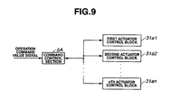
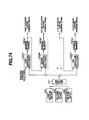
- FIG. 9 A control block diagram of a substantial part having the controller 5, the driving section 10b and the insertion portion driving mechanism 20 is shown in Fig. 9 .
- the controller 5 (refer to Fig. 2 ) includes a command control section 5A.
- the command control section 5A is arranged so that an operation command value signal from the operation command section 7 is supplied thereto.
- the command control section 5A Based on a supplied operation command value signal and state quantity detection signal, the command control section 5A performs computational processing or the like required to control the driving section 10b provided at an actuator control block 31.
- a plurality of first, second, ..., nth actuator control blocks 31a1 to 31an provided at each of the plurality of link members 21a constituting the insertion portion driving mechanism 20 of the bending portion 14 is electrically connected to the command control section 5A.
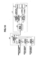
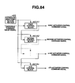
- Fig. 10 is a block diagram showing a specific configuration of the command control section 5A and the actuator control block 31 shown in Fig. 9 .
- the command control section 5A includes: an inputting section I/F 33 for inputting an operation command value signal from the operation command section 7; inputting sections I/F 34 and I/F 35 for inputting a setting command value from the setting value command section 8; and a central processing unit (e.g., a CPU) 32 that controls driving sections 10b in the first, second, ..., nth actuator control blocks 31a1 to 31an based on various command value signals inputted via the I/Fs 33 to 35.
- a central processing unit e.g., a CPU
- the inputting section I/F 33 is capable of inputting such an analog signal.
- the inputting section I/F 33 is capable of inputting such a digital signal.
- An analog setting value command signal required to consecutively move a plurality of link members 2 1 a can also be inputted through the inputting section I/F 34, while digital setting command values for changing parameters and the like can be inputted through the inputting section I/F 35.
- the inputting section I/F 34 and the inputting section I/F 35 may also be configured as one I/F.
- the actuator control block 31 performs various computational processing at high speed, and includes: a digital signal processor (hereinafter referred to as a DSP) 36 that creates and outputs a driving command value signal based on computation results; a control command value outputting section 37 that creates and outputs an operation output value signal based on a driving command value signal (servo command value signal) from the DSP 36; a motor 27 that is the driving section 10b whose rotation is controlled based on the operation output value signal (driving signal) from the control command value outputting section 37; a sensor 38 that is first detecting means such as an encoder that detects rotational positions of the motor 27, a potentiometer 23 that detects rotational angles of the link member 21a, or the like; and a signal inputting section 39 that detects a state quantity detection signal that is position information detected by the sensor 38 and outputs the state quantity detection signal to the DSP 36.
- a DSP digital signal processor
- the present invention is not limited to this arrangement. Instead, configurations are possible in which another actuator is used as the driving section 10b.
- Fig. 11 is a block diagram showing a specific configuration of the actuator control block
- Fig. 12 is a block diagram of the servo controller shown in Fig. 11 .
- the DSP 36 constitutes the servo controller 36A shown in Fig. 11 .
- the servo controller 36A creates an operation output value signal (driving signal) based on a supplied servo command value signal, and outputs the same to a driver (amplifier) 37a that is the control command value outputting section 37.
- the servo controller 36A may be replaced with the CPU 32 shown in Fig. 10 .
- the driver 37a amplifies the supplied operation output value signal to rotate the motor 27. Consequently, due to the rotation of the motor 27, the link member 21a shown in Fig. 5 rotationally moves. At this point, the sensor 38 creates a state quantity detection signal of the link member 21a and outputs the same to a detecting section (amplifier) 39a that is the signal inputting section 39.
- the detecting section 39a amplifies the supplied state quantity detection signal and outputs the same to the servo controller 36A. Accordingly, the servo controller 36A is arranged to perform rotational control of the motor 27 while comparing the supplied state quantity detection signal and servo command value signal.
- the servo controller 36A creates an operation output value signal (driving signal) based on a supplied servo command value signal and a state detection signal that is displacement information of the motor 27 obtained from the sensor 38 by performing PD control such as known proportional/differential control using a PD control section 40, and rotationally controls the motor 27 by supplying the operation output value signal thereto.
- PD control such as known proportional/differential control using a PD control section 40
- Figs. 13 to 15 are for describing attitude control of a bending portion having a multi-joint link structure and are explanatory diagrams corresponding to link members 21a1 to 21 a3 on the distal end portion 13 side, wherein: Fig. 13 is a diagram showing a state in which the distal end portion 13 side link member 21a1 assumes a predetermined distal end position and an attitude vector; Fig. 14 is a diagram showing states of other link members which are anticipated when the link member 21a1 shown in Fig. 13 is in the attitude state shown therein; and Fig. 15 is a diagram showing a state of a predetermined position and attitude vector when attitude control is independently performed on only the distal end portion 13 side link member 21a1.
- the command control section 5A of the controller 5 is arranged so that, when respectively performing attitude control on each of the plurality of link members 21a1 to 21an that constitute the bending portion 14, computational processing based on kinematics (forward kinematics and inverse kinematics), to be described later, is performed.
- kinematics forward kinematics and inverse kinematics
- Computational processing based on forward kinematics refers to computational processing for determining a position/attitude vector of a distal end portion when an angle of each joint (each link member 21a) is known
- computational processing based on inverse kinematics refers to computational processing for determining an angle of each joint (each link member 21a) when a position/attitude vector of a distal end portion is known.
- the command control section 5A performs computational processing based on a basic formula that quantifies robot kinematics, to be described later.
- a basic formula that quantifies robot kinematics is provided below.
- descriptions will only be given on movement involving three links and limited, as described above, to a two-dimensional plane.
- replacement of two-dimensional planar movement by a three-dimensional planar movement can be accommodated by similarly replacing known robotic coordinate conversion processing with processing by the DH convention (Denavit-Hartenberg convention).
- Velocity relationship between end - point and joint dx / dt J ⁇ dq / dt
- the notation # in Formula 4 represents a pseudo-inverse matrix.
- the first term of the left-hand side represents movement of the end-point position and the second term thereof represents movement of the respective joints other than the end-point. Therefore, in the case where the end-point position (the position of the distal end-side link member 21a1 and denoted by q1) is determined, attitudes of subsequent joints (other link members 21 a2 to 21an and denoted by q1, q2) are not uniquely determined.
- the command control section 5A of the controller 5 performs a calculation of a torque to be assigned to each link in order to control the link motion equations expressed as Formulas 3 and 4 provided above or, in other words, performs the calculations expressed as Formulas 7 and 8 to be described later, as shown in Fig. 15
- the command control section 5A is arranged so as to perform computational processing based on link position/attitude kinematics for the link members 21 a2 and 21a3 (q2 and q3) in the stage subsequent to the distal end portion and to perform computational processing based on an algorithm (stored in a memory, not shown) that performs independent driving control for the distal end-side link member 21a1 (q1).
- the servo controller 36A includes a control law computing section 36B to which is supplied: command value information (also including setting value information) such as setting command value signals including a servo command value signal at the distal end-side link member 21a1 or each link member 21a; and position feedback information (hereinafter referred to as position F/B information) such as a state quantity detection signal at each link member 21a.
- command value information also including setting value information
- position F/B information position feedback information
- control law computing section 36B Based on the supplied command value information and position F/B information, the control law computing section 36B performs computational processing for obtaining joint torque command value signals as driving command value signals corresponding to each link member 21a at the kinematics computing section 41 and the dynamics computing section 43, to be described later, and outputs the same to the driving section 10b.
- FIG. 17 A specific configuration of the control law computing section 36B is shown in Fig. 17 .
- the control law computing section 36B includes: the kinematics computing section 41 to which command value position information that is distal end position coordinates of the distal end-side link member 21a1 and joint position F/B information of each joint (each link member 21a) are inputted, and which uses the information to perform computational processing based on kinematics; the dynamics computing section 43 to which a computation result of the kinematics computing section 41, the command value information and the joint position F/B information are inputted, and which uses the information to perform dynamics computational processing to derive a dynamic part of a variation of each link member 21 a; and the control computing section 42 to which the command value information and respective computation results of the kinematics computing section 41 and the dynamics computing section 43 are inputted, and which, based on the information, performs computational processing of a joint torque command value signal required to control each link member 21 a.
- the control law computing section 36B controls the insertion portion driving mechanism (manipulator) 20 by supplying the created joint torque command value signal to the driving section 10b in the actuator control block 31.
- the manipulator 20 outputs joint position F/B information of each joint that is a state quantity detection signal detected by the sensor 38 in the actuator control block 31 to the kinematics computing section 41 and the dynamics computing section 43.
- Fig. 18 shows a schematic configuration of the dynamics computing section 43
- Fig. 19 shows a specific configuration of the dynamics computing section.
- a Jacobian (a velocity vector that is also referred to as J or Jacobian J), to be described later, which is a computation result of the kinematics computing section 41, the command value information and the joint position F/B information are inputted to the dynamics computing section 43, whereby the dynamics computing section 43 performs dynamics computational processing using the information in order to derive a dynamic part of a variation of each link member 21a or, more specifically, a position deviation, a Jacobian J, joint position velocity/acceleration of each link member 21a, and outputs the same as computational processing results.
- J a Jacobian
- the dynamics computing section 43 includes a forward kinematics computing section 44, a temporal differentiation computing section 45 and a temporal differentiation computing section 46.
- the forward kinematics computing section 44 performs computational processing based on above-described forward kinematics using the joint position F/B information. A computation result thereof is subtracted from distal end position information of the distal end-side link member 21a1 by a subtracter to derive a position deviation e of each link member 21 a.
- the joint position F/B information and the Jacobian J are inputted to the temporal differentiation computing section 45.
- the temporal differentiation computing section 45 creates a displacement of each link member 21 a or, more specifically, a Jacobian velocity ⁇ J/ ⁇ t and a joint position velocity ⁇ q/ ⁇ t.
- the temporal differentiation computing section 46 receives the joint position velocity ⁇ q/ ⁇ t as an input, and by performing temporal differentiation computational processing, creates a joint position acceleration ⁇ 2 q/ ⁇ t 2 .
- Fig. 20 shows a schematic configuration of the kinematics computing section 41
- Fig. 21 shows a specific configuration of the kinematics computing section 41.
- the command value information and the joint position F/B information are inputted to the kinematics computing section 41.
- the kinematics computing section 41 derives a Jacobian J of the distal end-side link member 21a1, a pseudo-inverse matrix J + of the Jacobian J and a null-space pseudo-inverse matrix (I-J + J) of the Jacobian J, and outputs the same as computational processing results.
- the kinematics computing section 41 includes a Jacobian computing section 47, a pseudo-inverse matrix computing section 48, and a Jacobian null-space computing section 49.
- the Jacobian computing section 47 performs computational processing for obtaining a Jacobian J based the command position information and the position F/B information, and outputs the obtained Jacobian J to the control computing section 42 shown in Fig. 17 , the pseudo-inverse matrix computing section 48 and the Jacobian null-space computing section 49.
- the pseudo-inverse matrix computing section 48 receives the Jacobian J as input, and by performing generalized inverse matrix computational processing thereon, creates a pseudo-inverse matrix J + and outputs the same to the control computing section 42 shown in Fig. 17 and the Jacobian null-space computing section 49.
- the Jacobian null-space computing section 49 By performing Jacobian null-space computational processing on the supplied Jacobian J and pseudo-inverse matrix J + , the Jacobian null-space computing section 49 creates a pseudo-inverse matrix I-J + J and outputs the same to the control computing section 42 shown in Fig. 17 .
- the Jacobian J, the pseudo-inverse matrix J + of the Jacobian J and the Jacobian null-space pseudo-inverse matrix (I-J + J) are to be supplied to the control computing section 42 shown in Fig. 17 as computational processing results of the kinematics computing section 41.
- the control computing section 42 performs PD control based on the above-described command values and state quantity.
- K NULL represents a coefficient to be used by the control computing section 42.
- a joint torque ⁇ can be determined by applying various computational processing results obtained by the kinematics computing section 41, the dynamics computing section 43 and the control computing section 42 shown in Fig. 17 .
- the entire bending portion is desirably provided with flexible dynamic characteristics.
- the insertion portion driving mechanism 20 achieves such dynamic characteristics by providing the distal end portion thereof with a combination of a spring 20a and a damper 20b such as those shown in Fig. 22 .
- control computing section 42 A control law implemented by the control computing section 42 will be described below.
- a motion equation of dynamic characteristics shown in Fig. 22 may be expressed as Formula 9.
- F M ⁇ ⁇ 2 ⁇ x ⁇ t 2 + D ⁇ ⁇ x ⁇ t + Kx
- the dynamic characteristics of the distal end having compliance characteristics may be expressed as Formula 10.
- M ⁇ ⁇ 2 ⁇ X ⁇ t 2 + D ⁇ ⁇ X - X D ⁇ t + K ⁇ X - X D F TIP
- a joint force ⁇ F equivalent to and opposing F TIP may be expressed as Formula 11.
- ⁇ F J T q ⁇ F
- a motion equation when an external force F is applied from the exterior environment in a state where the distal end portion is immobilized may be expressed with respect solely to a distal end portion mass M as Formula 12.
- H q ⁇ ⁇ 2 ⁇ q ⁇ t 2 + h q ⁇ q ⁇ t + g q ⁇ + J ⁇ q T ⁇ F
- Formula 14a and Formula 14b may be derived as manipulator motion equations from Formula 13.
- compliance characteristics may be expressed as Formula 15.
- M q ⁇ ⁇ 2 ⁇ X ⁇ t 2 + D ⁇ ⁇ X - X D ⁇ t + K ⁇ X - X D K F ⁇ F
- Formula 16 expresses the same relationship as Formula 7, albeit in a different form. In this case, for simplicity, a controlling expression of a torque command where the distal end portion has spring characteristics K is derived.
- Formula 18 indicates what kind of a torque command was created by each joint when K is set as desired compliance characteristics.
- the first item of the left-hand side of Formula 4 represents a movement of a hand-held position while the second term thereof represents a movement of a joint.
- the command control section 5A of the controller 5 performs torque calculations in real-time using Formula 7 and Formula 8, as described above.
- computational processing based on an algorithm for drive controlling the driving section 10b may be performed on a value corresponding to the second term of the Formula 7 as a result of computational processing of weighting in accordance with a movable range of the link member 21a.
- computational processing is performed by changing the algorithm of the second term of Formula 7 or (I-J # .J) ⁇ (d 2 q/dt 2 ) to, for example a weighting function ⁇ that is a parameter like that shown in Fig. 24 .
- the weighting function ⁇ performs computational processing such that, when determining an angle of each link member 21a, weighting increases at the limit of the movable range of each link and decreases in the vicinity of a neutral position in the movable range. Therefore, the coefficient is for setting weighting of the attitude of each link to an attitude that is as close to neutral as possible, and for eliminating forced attitudes and limiting movement to a mobile range.
- a range of ⁇ 90 degrees is set in advance as a tolerable range of an angle formed by adjacent link members 21a.
- the parameter is arranged so that the angle formed by adjacent link members 21 a does not assume an acute angle.
- each link member 21a of the insertion portion driving mechanism 20 is mobile and smooth.
- weighting function ⁇ weighting functions such as those represented by any of the graphs shown in Figs. 25 to 29 to be described later may be used.
- the ordinates of Figs. 25 to 29 indicate K NULL as expressed in Formula 8, while abscissas thereof indicate a movable range of each link member 21a (a detected angle of each link member 21a).
- the positive movable limit value is set to 90 degrees and the negative movable limit value is set to -90 degrees.
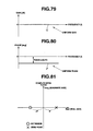
- Fig. 25 is a graph showing characteristics of a first variation of the weighting function ⁇ .
- the weighting function ⁇ is a linear function, and is a weighting function obtained by performing computational processing corresponding to position variations of each link member 21 a as shown below.
- ⁇ a ⁇ q i - q i_ ⁇ org , where ⁇ represents a negative definite value, qi represents each link position, and qi_org represents a link origin position.
- Fig. 26 is a graph showing characteristics of a second variation of the weighting function ⁇ .
- the weighting function ⁇ is a quadratic function, and is a weighting function obtained by performing computational processing corresponding to position variations of each link member 21 a as shown below.
- ⁇ a ⁇ q i - q i_ ⁇ org 2 , where, in this case, ⁇ represents a negative definite value.
- Fig. 27 is a graph showing characteristics of a third variation of the weighting function ⁇ .
- the weighting function ⁇ is a weighting function obtained by performing computational processing of partial differentiation corresponding to position variations of each link member 21 a as shown below.
- W i q i - q i_ ⁇ org / q i max - q i min 2
- ⁇ represents a negative definite value
- qi represents each link position
- qi_org represents a link origin position
- qi_max represents a link upper limit angle value
- qi_min represents a link lower limit angle value
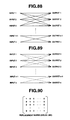
- Fig. 28 is a graph showing characteristics of a fourth variation of the weighting function ⁇ .
- the weighting function shown in Fig. 28 can be realized as a weighting function that approaches as much as possible the vicinity of the movable limit value by adding an offsetting value of ⁇ to Formula 22, to be described below, to newly set ⁇ and assuming ⁇ to be a positive definite value.
- ⁇ represents a positive definite value.
- Fig. 29 is a graph showing characteristics of a fifth variation of the weighting function ⁇ .
- the weighting function ⁇ may also be arranged to use an absolute value of a trigonometrical function such as that including the dashed line portion shown in the diagram as expressed by Formula 22.
- W i a ⁇ tan q i - q i_ ⁇ org , where, in this case, ⁇ represents a negative definite value.
- a weighting function that uses a singularity of the manipulator attitude is used for the weighting function ⁇ .
- a manipulability indicator M with respect to the Jacobian J may be defined as shown in Formula 23 below, whereby the manipulability indicator M may be replaced with the weighting function ⁇ .
- weighting functions for several types of attitude control have been shown, in some cases, weighting functions can be combined so that different weighting combinations are selectively performed for each link interval using shaft switching means to be described later.
- weighting functions shown in Figs. 25 to 29 or weighting functions using a manipulability indicator M such as those expressed by Formula 23 or Formula 24 can be stored for each table.
- the controller 5 (more specifically, the CPU 32) selects a weighting function based on any one of a plurality of tables, and performs computational processing of an angle of each link member 21a or each angle of each link member with respect to the entire manipulator.
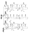
- Figs. 30 to 38 are related to the first embodiment of the present invention.
- Fig. 30 is a block diagram showing a specific configuration of the controller 5 of the endoscope apparatus 1; and Figs. 31 and 32 are diagrams describing attitude control of the insertion portion driving mechanism 20 that constitutes the bending portion 14, wherein Fig. 31 shows a state in which a distal end-side link member 21a1 is point-locked, and Fig. 32 shows a state in which point-locking the distal end-side link member 21a1 provides a subsequent-stage link member with redundancy.
- Fig. 33 is a block diagram showing a specific configuration of the point lock computing section 50 shown in Fig. 30 ; Fig.
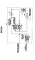
- Fig. 34 is a block diagram showing a specific configuration of the inverse kinematics computing section 52 shown in Fig. 33 ;
- Fig. 35 is a diagram explaining attitude control when only the distal end-side link member 21a1 is point-locked; and
- Fig. 36 is an explanatory diagram explaining attitude control when a fourth link member 21 a4 is further point-locked.
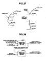
- Fig. 37 is an explanatory diagram explaining attitude control in a case where two locations are point-locked; and
- Fig. 38 is a block diagram showing an internal configuration of a controller in which the point lock computing section is provided at each link member 21 a.
- the controller 5 includes the servo controller 36A that performs attitude control of the bending portion 14 as described earlier.
- the servo controller 36A is provided with a point lock computing section 50 having computational processing functions of the control law computing section 36B.
- the servo controller 36 uses the point lock computing section 50 to compute respective angles of the plurality of link members 21 a so that a position and a direction designated by the operation command section 7 is maintained when a link member 21a1 designated by the operation command section 7 as well as other link members 22 contiguous to the link member 21a1 pass through the position, and based on the computation results, controls the driving section 10b to rotationally move the plurality of link members 21a.
- the servo controller 36 is also arranged so that when performing computational processing for determining the respective angles of the plurality of link members 21a using the point lock computing section 50, computational processing is performed by manually or automatically selecting any of respective tables storing weighting functions having characteristics such as those shown in Figs. 25 to 29 and by using a weighting function based on the table.
- distal end command value information such as a setting command value signal and the like including a servo command value signal at the distal end-side link member 21a1 and position F/B information such as a state quantity detection signal at the distal end-side link member 21a1 are supplied to the point lock computing section 50.
- the point lock computing section 50 Based on the supplied distal end command value information and position F/B information, the point lock computing section 50 performs computational processing at a distal end link root coordinate position calculating section 51 and an inverse kinematics computing section 52, to be described later, for obtaining a servo position command signal (including a joint torque command value signal) as a driving command value signal corresponding to each link member 21 a.
- the point lock computing section 50 computes respective angles of the plurality of link members 21 a so that a position and a direction designated by the operation command section 7 is maintained when a link member 21a1 designated by the operation command section 7 as well as other link members 22 contiguous to the link member 21a1 pass through the position, and outputs the computation results as a servo position command value signal to the driving section 10b.
- the distal end command value information and position F/B information used in the computational processing by the point lock computing section 40 represents an angle mutually formed by the plurality of link members 21a as well as a variation of the angle that are detected by a sensor 38 that is first detecting means.
- the bending portion 14 having the insertion portion driving mechanism 20 will be bent in a shape conforming to the shape of a tube cavity to which the bending portion 14 is inserted.
- Fig. 31 shows a state in which only the distal end-side link member 21a1 is point-locked at an instructed predetermined attitude state.
- the point lock computing section 50 When performing control to such an attitude state, if the joint member 21b1 of the distal end portion-side link member 21a1 is assumed to be point lock R1 as shown in Fig. 32 , the point lock computing section 50 performs computational processing of point lock coordinates of the point lock R1 to create a servo position command signal necessary for performing attitude control of the two-dimensional position and direction of the distal end-side link member 21a1.
- a link portion 20B constituted by a plurality of link members 21a2, 21a3 and 21a4 subsequent to the point lock R1 acquires redundancy through the above-described attitude control, and can now change to unregulated, arbitrary attitudes as represented by the dashed lines in the diagram.
- FIG. 33 A specific configuration of the point lock computing section 50 is shown in Fig. 33 .
- the point lock computing section 50 includes the distal end link root coordinate position calculating section 51 and the inverse kinematics computing section 52.
- Joint angle information of a link member 21a, distal end command value information that is position information of the distal end-side link member 21a1, and position F/B information are inputted to the distal end link root coordinate position calculating section 51. Based on the information, the distal end link root coordinate position calculating section 51 calculates a distal end link root coordinate position of the distal end-side link member 21a1, and outputs the calculation result to the inverse kinematics computing section 52.
- Distal end command value information and position F/B information from the distal end link root coordinate position calculating section 51 are inputted to the inverse kinematics computing section 52. Based on the information, the inverse kinematics computing section 52 performs computational processing of root coordinate positions of link members 21a subsequent to the distal end-side link member 21a1, and creates and outputs servo position command value signals for link members other than the distal end-side link member 21a1.
- the inverse kinematics computing section 52 includes: a mechanism parameter computing section 53; a forward kinematics computing section 54; a Jacobian computing section 55; a gain 56; a matrix computing section 57; and an integrating circuit 58.
- the mechanism parameter computing section 53 performs computational processing based on the position F/B information to create a distal end link offsetting value for adjusting and controlling the distal end-side link member 21a1 to a subtle attitude.
- a difference between the distal end link offsetting value and the distal end command value information is obtained, and a difference is once again obtained between the difference value and the command value F/B information computationally processed by the forward kinematics computing section 54. Accordingly, the difference value is supplied to the gain 56 as second-stage position command information.
- the gain 56 amplifies the supplied second-stage position command information and outputs the same to the matrix computing section 57.
- the Jacobian computing section 55 creates a Jacobian J by performing computational processing based on command value information, and outputs the same to the matrix computing section 57.
- the matrix computing section 57 Based on the supplied second stage position command information, the matrix computing section 57 performs matrix computation processing for determining an attitude (angle) of a link member 21a of the second stage and thereafter corresponding to the attitude state of the link member 21a, and after performing integration processing on the obtained computation result at the integrating circuit 58, outputs the same as a servo command value signal for the second and subsequent stages to the driving section 10b.
- the output of the integrating circuit 58 or, in other words, the servo command value signal for the second and subsequent stages is fed back to a deviation value of the distal end command value information and position F/B information via the Jacobian computing section 55 and the forward kinematics computing section 54. This is performed in consideration of minimizing occurrences of singular solutions when solving inverse kinematics.
- a link member 21a of the second and subsequent stages will be controlled so as to assume subtle attitudes in conjunction with attitude control of the distal end-side link member 21a1.
- Fig. 35 shows a bending state of the bending portion 14 on which attitude control is performed by the point lock computing section 50 according to the first embodiment.
- the point lock computing section 50 creates a servo position command value signal to point-lock the distal end-side link member 21a1 at the point lock coordinates (two-dimensional position and direction) of the point lock R1, and provides the servo position command value signal to the driving section 10b to control the same.
- the distal end-side link member 21a1 of the bending portion 14 is point-locked at the instructed attitude vector (two-dimensional position and direction) at point lock R1, as shown in Fig. 35 .
- the point lock computing section 50 computes respective angles of the plurality of link members 21 a so that a position and a direction designated by the operation command section 7 is maintained when a link member 21a1 designated by the operation command section 7 as well as other link members 21a contiguous to the link member 21a1 pass through the position, and based on the computation results, controls the driving section 10b so as to rotationally move the plurality of link members 21 a.
- the point lock computing section 50 When computationally processing the respective angles of the plurality of link members 21a, the point lock computing section 50 performs computational processing using a weighting function based on a weighting function table designated by the setting value command section 8. Consequently, forced attitudes of the plurality of link members 21a or the manipulator 20 can be eliminated, an angle necessary for enabling movement in a mobile range can be acquired for each of the plurality of link members 21a, and based on the computation results, rotational movement of each link member 21a is controlled.
- the endoscope apparatus 1 when inserting the insertion portion 9 into the large intestine, the operator inserts the insertion portion 9 having the bending portion 14 via the anus. Then, when the distal end portion 14 of the insertion portion 9 reaches the sigmoid colon segment, the servo controller 36A point-locks the distal end-side link member 21a1 to a two-dimensional position and direction designated by the operation command section 7.
- Fig. 36 is a diagram showing a bending state of the bending portion 14 in a case where attitude control is performed so that there are two point-locked locations
- Fig. 37 is an explanatory diagram explaining a computing method used by the point lock computing section 50 for designating two point-locked locations
- Fig. 38 is a block diagram showing a configuration of a controller required for designating and controlling a plurality of point-locked locations.
- a plurality of the point lock computing sections 50 (point lock computing sections 50A1 to 50An) is provided in correspondence to the plurality of link members 21a, whereby the point lock computing sections 50 are connected so that a servo command value signal for obtaining a subsequent-stage point lock coordinate position is inputtable to the point lock computing section 50 of the subsequent stage.
- the point lock computing section 50A2 corresponding to the subsequent-stage link member 21a2 acquires a servo position command value signal that is an output of the point lock computing section 50A1 as an input signal for computing a second point lock position.
- the servo controller 36A may be configured by, in a similar manner, subsequently providing point lock computing sections 50A3 to 50An in a quantity corresponding to the number of link members 21 a to be point-locked among the plurality of link members 21a.
- the point lock location of the joint member 21b3 (q3) is assumed to be a virtual distal end position, as shown in Fig. 37 .
- a link member 21a corresponding to q4 that has q3 as a virtual distal end position becomes the virtual distal end-side link member 21a.
- Designation of a link member 21a to be point-locked among the plurality of link members 21 a is to be performed at the operation command section 7.
- Fig. 36 shows a bending state of the bending portion 14 in a case where attitude control is performed so that there are two point-locked locations.
- the point lock computing sections 50A1 and 50A4 respectively create a servo position command value signal for point-locking the distal end-side link member 21a1 and the fourth-stage link member 21 a4 at point lock coordinate values of point lock R1 and point lock R2, and provide the signals to the driving section 10b to control the same.
- the distal end-side link member 21a1 of the bending portion 14 is point-locked at the instructed attitude vector (two-dimensional position and direction) at point lock R1.
- the fourth-stage link member 21 a4 is point-locked at the instructed attitude vector (two-dimensional position and direction) at point lock R1.
- the point lock computing sections 50A1 and 50A2 compute respective angles of the plurality of link members 21 a so that the position and a direction designated by the operation command section 7 are maintained when link members 21a1 and 2 1 a4 designated by the operation command section 7 as well as other link members 21 a respectively contiguous to the link members 21a1 and 21 a4 pass through the position, and based on the computation results, controls the driving section 10b so as to rotationally move the plurality of link members 21 a.
- the endoscope apparatus 1 when inserting the insertion portion 9 into the large intestine, the operator inserts the insertion portion 9 having the bending portion 14 via the anus. Then, when the distal end portion 14 of the insertion portion 9 reaches the sigmoid colon segment, the servo controller 36A point-locks the distal end-side link member 21a1 to a two-dimensional position and direction designated by the operation command section 7.
- the servo controller 36A point-locks the designated link member 21 a4 to a two-dimensional position and direction obtained by the point lock computing section 50A5.
- the bending portion 14 is to be inserted while performing bending movements into shapes conforming to the shape of the sigmoid colon segment.
- attitude control having redundancy is performed as described above.
- the present invention is not limited to this arrangement. Instead, the present invention may be configured so that a three-dimensional position and direction of an arbitrary link member 21 a are point-locked.
- control when withdrawing the insertion portion 9 from the inside of a tube cavity such as the large intestine into which the insertion portion 9 has been inserted, control may be performed so that, for example, attitude control of the entire bending portion 14 or a part of the link members 21a is released by suspending driving of the driving section 10b so that an unloaded free state (a state that enables free rotational movement) is attained. Consequently, the insertion portion 9 can be readily withdrawn from inside the tube cavity.
- the present invention may be configured by providing driving shaft selecting means 60 and driving shaft recognizing means 61 so that a link member 21 a for which attitude control is released to change to a free state is designated based on an operation by the operator.
- the driving shaft selecting means 60 is used by the operator to select a link member 21 a to be changed to a free state, and the selected operation signal is supplied to the driving shaft recognizing means 61. Based on the operation signal, the driving shaft recognizing means 61 recognizes position information based on the selected link member 21a, and outputs a control signal declaring the intent to release attitude control of the recognized link member 21a to the control law computing section 36B (refer to Fig. 16 ).
- control law computing section 36B performs attitude control of the link member 21a, and at the same time, controls the driving section 10b so that attitude control is released for link members 21 a based on the control signal. Consequently, the degree of freedom of the bending attitude of the bending portion 14 increases, and the manipulability of the insertion portion 9 can be further enhanced.
- an arbitrary link member 21a including the distal end-side link member among a plurality of link members 21 a constituting the bending portion 14 of the insertion portion 9 can be point-locked, and attitude control can be performed over the other link members so that arbitrary attitudes having redundancy can be taken, it is now possible to insert the bending portion 14 of the insertion portion 9 in a shape conforming to the interior shape of a tube cavity. As a result, advantageous effects such as improvement of insertability of the insertion portion can be achieved.
- the present embodiment is provided with an offset command inputting section 62 that changes the position or direction of the point-locked distal end-side link member 21a1 or an arbitrary link member 21a other than the link member 21a1 by only a preset quantity.
- the offset command inputting section 6 it is now possible to adjust the point-locked distal end-side link member 21a1 or an arbitrary link member 21a other than the link member 21a1 by subtly changing (offsetting) the position or the direction thereof.
- the offset command inputting section 62 is provided in the servo controller 36A, and creates and outputs offset command value information indicating whether an arbitrary link member 21a is to be offset by a preset quantity.
- the setting quantity of the offset command inputting section 62 may be arranged to be variable.
- the offset command value information is added to a servo command value signal, and then subjected to PD control such as proportional/differential control by the PD control section 40 as was described with reference to Fig. 12 to become an operation command value signal (driving signal) to be provided to the motor 27. Consequently, since the motor 27 is rotationally controlled based on an operation output-side signal to which an offset quantity has been added, the attitude (position or direction) of the designated link member 21 a will be subtly offset.
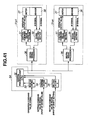
- the servo controller 36A may also be configured by combining the driving shaft selecting means 60 and the driving shaft recognizing means 61 shown in Fig. 39 with the offset command inputting section 62 shown in Fig. 40 . Such a configuration is shown in Fig. 41 .
- the command control section 5A having the servo controller 36A is arranged so that offset command value information from the offset command inputting section 62 is inputted to the inputting I/F 34 while a control signal such as shaft setting information from the driving shaft recognizing means 61 is inputted to the inputting I/F 35.
- the CPU 32 is to perform computational processing for controlling the attitude of each link member of the bending portion 14.
- Other configurations and advantageous effects are the same as those of the configuration shown in Fig. 10 .
- the bending portion 14 having the insertion portion driving mechanism 20 constituting a manipulator has been described as being provided at the insertion portion 9 of the endoscope 2
- the bending portion 14 may be arranged to be provided at an insertion portion of an endoscope insertion aiding device that aids the insertion of the insertion portion 9 into a tube cavity by allowing insertion of the insertion portion 9 of the endoscope 2.
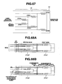
- Fig. 42 is a schematic configuration diagram showing a configuration of an insertion portion driving mechanism in which a load detecting section for detecting a load created by coming into contact with an intestinal wall is provided at each link member;
- Fig. 43 is a block diagram showing a dynamics computing section included in the load detecting section shown in Fig. 42 and the control law computing section 36B;
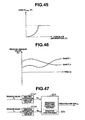
- Fig. 44 is a graph showing characteristics of a detection result from the load detecting section and a coefficient that determines a weighting function;
- Fig. 45 is a graph showing an example of characteristics that differs from those shown in Fig. 44 .
- Figs. 42 is a schematic configuration diagram showing a configuration of an insertion portion driving mechanism in which a load detecting section for detecting a load created by coming into contact with an intestinal wall is provided at each link member;
- Fig. 43 is a block diagram showing a dynamics computing section included in the load detecting section shown in Fig. 42 and the control law computing section 36B;
- Fig. 44 is
- Fig. 46 and 47 present a first variation of the second embodiment, wherein: Fig. 46 is a graph showing characteristics of a detection result from the load detecting section and time; and Fig. 47 is a block diagram showing a substantial block configuration for implementing the first variation of the second embodiment.
- Figs. 48 and 49 present a second variation of the second embodiment, wherein: Fig. 48 is a graph showing characteristics of a detection result from a displacement sensor used as a load detecting section and time; and Fig. 49 is a block diagram showing a substantial block configuration for implementing the second variation of the second embodiment.
- the second embodiment describes specific processing for automatically determining a weighting function that is an optimum parameter based on a detection result of a load detecting section 60, to be described later, in the case where, when inserting the bending portion 14 into a tube cavity, computational processing is performed using a weighting function on angles of a plurality of link members 21 constituting the bending portion 14 or on an angle of an arbitrary link member 21 among the plurality of link members 21. Otherwise, descriptions on points similar to the first embodiment described above will be omitted.
- the load detecting section 60 is respectively provided as load detecting means (second detecting means) at each link member 21a constituting the bending portion 14 of the insertion portion 9.
- the load detecting section 60 is constituted using, for example, a tension sensor such as a strain gauge, and is respectively provided in a covering tube (not shown) covering each link member 21a so as to be disposed at preset locations (for example, four locations when provided every 90 degrees) on the circumferential surface of each link member 21 a.
- the load detecting section 60 detects a force (also referred to as tension) created from coming into contact with the intestinal wall or the like, and outputs the detection result as force F/B information to the dynamics computing section 43A.
- a force also referred to as tension
- the dynamics computing section 43A is provided with a weighting switching computing section 62 as setting means that, based on the detection result from the load detecting section 60, creates a parameter value necessary for performing computational processing for determining a weighting function and performs computational processing of a weighting function in accordance with the parameter value.
- the weighting switching computing section 62 has weighting function tables 62a respectively storing, for example, the weighting functions shown in Figs. 25 to 29 or weighting functions using a manipulability indicator M such as those expressed by Formula 23 or Formula 24.
- the weighting function table 62a can also be arranged to be provided in the command control section 5A or the like instead of in the weighting switching computing section 62.
- the dynamics computing section 43A causes the weighting switching computing section 62 to perform computational processing on angles of the plurality of link members 21a using a weighting function based on position F/B information that is an angular displacement of each link member 21a, and outputs a weighted servo command value signal to the driving section 10b.
- the weighting switching computing section 62 creates a parameter value necessary for performing computational processing for determining a weighting function based on a detection result from the load detecting section 60.
- the weighting switching computing section 62 performs computational processing using a weighting function of any of the weighting function tables 62a preset by the operation command section 7 and the created parameter value.
- ⁇ - K NULL F ⁇ ⁇ q ⁇ t + ⁇ I - J # ⁇ J ⁇ t ⁇ q ⁇ t the weighting switching computing section 62 determines K NULL that is a parameter value from a change in (F) that is a detection result from the load detecting section 60 expressed in Formula 25.
- K NULL that is the parameter value increases until the value of the force FB information reaches a presetting value, and consistently takes a constant value after the setting value.
- K NULL . gain changes linearly in accordance with the force F/B information, and becomes a parameter value that saturates at a preset arbitrary threshold.
- the setting value of the threshold of the parameter value K NULL can also be inputted via the setting value command section 8.
- a weighting function value ⁇ is attained that realizes an attitude not subjected to the action of disturbance with respect to disturbances such as coming into contact with the intestinal wall.
- the weighting function parameter value K NULL may take the form of non-linear functions expressed by Formula 26 and Formula 27 below.
- the weighting switching computing section 62 is capable of obtaining an optimum weighting function through computational processing performed by changing parameter values when weighting an angle of each link member 21a and performing computational processing based on force F/B information from the load detecting section 60.
- a servo command value signal weighted in accordance with force F/B information from the load detecting section 60 can be obtained by the dynamics computing section 43A, thereby eliminating forced attitudes of an arbitrary link member 21a or the entire manipulator 20 and enabling movements within a mobile range.
- precise dynamics control may be implemented using force information feedback information on the state quantity detection signal by arranging as a load sensor for operating the bending portion 14.
- the endoscope apparatus 1 When inserting the insertion portion 9 into a tube cavity, the endoscope apparatus 1 according to the present embodiment is capable of performing insertion in a safer manner even when the bending portion 14 of the insertion portion 9 comes into contact with the intestinal wall or the like inside the tube cavity and the contact state continues.
- the present embodiment is arranged so that, when performing computational processing of weighting on angles of the plurality of link members 21a based on a detection result of the load detecting section 60, a weighting function for the entire manipulator 20 which takes time into consideration and also causes a link member 21 a that is in contact with the intestinal wall or the like to avoid contact is obtained.
- a weighting function for the entire manipulator 20 which takes time into consideration and also causes a link member 21 a that is in contact with the intestinal wall or the like to avoid contact is obtained.
- Figs. 46 and 47 describe a first variation of the second embodiment, wherein: Fig. 46 is a graph showing characteristics of a detection result from the load detecting section and time; and Fig. 47 is a block diagram showing a configuration of a substantial part including the weighting switching computing section in the dynamics computing section.
- the ordinate shown in Fig. 46 represents a tension sensor value (force F/B information) obtained from a tension sensor (strain gauge) that is the load detecting section; the abscissa represents time (t); and axes 1 and 2 respectively indicate first and second link members 21 a.
- the tension sensor value of the second link member 21 a2 from the load detecting section 60 decreases as time advances, while the tension sensor value of the first (distal end-side) link member 21a1 from the load detecting section 60 increases after reaching a given predetermined point in time.
- the present embodiment is arranged to perform computational processing to determine a weighting function capable of avoiding such a contact state based on the tension sensor value detected at that point even when a contact state of an arbitrary link member 21a with the intestinal wall continues.
- a weighting function that weights the entirety of the plurality of link members 21a or, in other words, the entire manipulator 20 is created instead of a weighting function for each of the link members 21a as was used in the second embodiment.
- temporal integration computing sections 61a1, 61a2, ..., 61 an respectively provided at each of the plurality of link members 21 a are arranged to be connected to the weighting function switching computing section 62A in the dynamics computing section 43.
- Tension sensor values F1, F2, ..., Fn from the load detecting section 60 provided at the respective link members 21a are respectively supplied to each of the temporal integration computing sections 61a1, 61a2,..., 61 an.
- the temporal integration computing section 61a1 performs temporal integration computation processing for obtaining an evaluation function using the supplied tension sensor value F1, and an obtained evaluation function SF1 is outputted to the weighting function switching computing section 62A.
- Temporal integration computation processing is performed in the same manner by the temporal integration computing sections 61a2,..., 61 an to respectively determine evaluation functions SF2, ..., SFn to be respectively outputted to the weighting function switching computing section 62A.
- the weighting function switching computing section 62 performs averaging according to the following formula (Formula 31) using the respectively supplied evaluation functions S FK to determine an evaluation function S SUM , and further, using the evaluation function S SUM , obtains a weighting function ⁇ for the entire manipulator 20 by performing computational processing based on Formula 32.
- Formulas 31 and 32 are provided below.
- S FK Weighting function ⁇ Fi l / S Fi / S SUM
- the weighting function tables 62a used in the above second embodiment may be provided in the weighting switching computing section 62A, whereby a weighting function in at least one of the weighting function tables and a weighting function ⁇ Fi obtained by the computational processing may be switchably used as needed. As a result, a wide range of bending control can be performed depending on the insertion state of the insertion portion 9.
- the present embodiment is not limited to such a configuration. Instead, it is also possible to obtain a weighting function for the entire manipulator 20 regardless of the availability of the tension sensor that is the load detecting section 60. Such a second variation will be presented below.
- Figs. 48 and 49 are for describing a second variation of the second embodiment, wherein: Fig. 48 is a graph showing characteristics of a detection result, from an actuator control block and time; and Fig. 49 is a block diagram showing a configuration of a substantial part including the weighting switching computing section in the dynamics computing section.
- the ordinate shown in Fig. 48 represents a displacement (P) of an angle by which each link member 21 a moves obtained from a sensor; the abscissa represents time (t); and axes 1 and 2 respectively indicate first and second link members 21 a.
- the displacement value (P) of the second link member 21 a2 from the sensor 38 decreases as time advances, while the displacement value (P) of the first (distal end-side) link member 21a1 from the sensor 38 increases after reaching a given predetermined point in time.
- the present embodiment is arranged to perform computational processing to determine a weighting function capable of avoiding such a contact state based on the displacement value detected at that point even when a contact state of an arbitrary link member 21 a with the intestinal wall continues.
- a weighting function that weights the entirety of the plurality of link members 2 1 a or, in other words, the entire manipulator 20 is created instead of a weighting function for each of the link members 21a as was used in the second embodiment.
- temporal integration computing sections 61A1, 61A2, ..., 61An respectively provided at each of the plurality of link members 21 a are arranged to be connected to the weighting function switching computing section 62B in the dynamics computing section 43.
- Displacement values P1, P2, ..., Pn from the sensor 38 in the actuator control block 31 provided in the respective link members 21 a are respectively supplied to each of the temporal integration computing sections 61A1, 61A2,..., 61An.
- the temporal integration computing section 61A1 performs temporal integration computation processing for obtaining an evaluation function using the supplied displacement value P1, and outputs an obtained evaluation function SP1 to the weighting function switching computing section 62B.
- Temporal integration computation processing is performed in the same manner by the temporal integration computing sections 61A2, ..., 61An to respectively determine evaluation functions SP2, ..., SPn to be outputted to the weighting function switching computing section 62B.
- the weighting function switching computing section 62B performs averaging according to Formula 34 below using the respectively supplied evaluation functions S PK to determine an evaluation function S SUM , and further, using the evaluation function S SUM , obtains a weighting function ⁇ i for the entire manipulator 20 by performing computational processing based on Formula 35.
- Formulas 34 and 35 are provided below.
- the weighting function tables 62a used in the above second embodiment may be provided in the weighting function switching computing sections 62A and 62B, whereby a weighting function in at least one of the weighting function tables and a weighting function ⁇ i obtained by the above-mentioned computational processing may be switchably used as needed. As a result, a wide range of bending control can be performed depending on the insertion state of the insertion portion 9.
- the distal end-side link member 21a1 among the plurality of link members 21 a constituting the bending portion 14 of the insertion portion 9 can be point-locked, and attitude control can be performed over the other link members 21a so that arbitrary attitudes having redundancy can be assumed, it is now possible to insert the bending portion 14 of the insertion portion 9 in a shape conforming to the interior shape of a tube cavity. As a result, advantageous effects such as improvement of insertability of the insertion portion can be achieved.
- the endoscope apparatus 1 enables automatic determination of an optimum weighting function based on a detection result of a load detecting section 60 in the case where, when inserting the bending portion 14 into a tube cavity, computational processing is performed using a weighting function on angles of a plurality of link members 21 a constituting the bending portion 14 or on an angle of an arbitrary link member 21a among the plurality of link members 21a. Consequently, since forced attitudes of the plurality of link members 2 1 a or the manipulator 20 can be eliminated and an angle necessary for enabling movement in a mobile range can be acquired for each of the plurality of link members 21a, it is now possible to perform insertion into a tube cavity in a smooth manner.
- the present invention is not limited to this example. Instead, the present invention may be configured so that a three-dimensional position and direction are point-locked.
- the bending portion 14 having the insertion portion driving mechanism 20 constituting a manipulator has been described as being provided at the insertion portion 9 of the endoscope 2
- the bending portion 14 may be arranged to be provided at an insertion portion of an endoscope insertion aiding device that aids the insertion of the insertion portion 9 into a tube cavity by allowing insertion of the insertion portion 9 of the endoscope 2.
- the present third embodiment primarily differs from the above first embodiment in that bending movement of the bending portion 14 is performed by respectively rotationally moving the plurality of link members 21 a by respectively pulling or relaxing a plurality of bending operation wires 130A (130A1, 130A2, ..., 130An). Otherwise, descriptions on points similar to the first embodiment described above will be omitted.
- Fig. 50 is a top view showing a configuration of a bending portion whose driving mechanism is constituted by a bending operation wire, a driving pulley and a free pulley;
- Fig. 51 is a side view showing a suspended state of a bending operation wire provided between respective link members of the bending portion shown in Fig. 50 ;
- Fig. 52 is a configuration diagram showing a configuration of a driving pulley provided with the driving shaft shown in Fig. 50 ;
- Fig. 53 is a top view showing a configuration of the free pulley shown in Fig. 50 .
- the present third embodiment is arranged so that the driving section 10b is disposed inside the operation section 10, and a plurality of motors 27 of the driving section 10b is connected through the inside of the insertion portion 9 to the respective bending operation wires 130A.
- the driving section 10b respectively rotationally moves the plurality of link members 21a1, 21a2, ..., 21an by pulling or relaxing the plurality of bending operation wires 130A1, 130A2, ..., 130An.
- the bending operation wires 130A1 to 130An are arranged to be connected to driving shafts of the motors 27 via gears and sprockets, not shown.
- the bending operation wires 130A1 to 130An are extended in the insertion portion 9, and proximal end portions thereof are suspended by a driving pulley 123 and a free pulley 125 of a rearmost end-side link member 21 an among the plurality of link members 21a1, 21a2, ..., 21 an.
- the respective intervals between the link member 21an and the other link members 21a1,.... 21a(n-1) are arranged to be suspended by other bending operation wires 131 a1, 131a2, ..., 131 am (where m is a natural number).
- the numbers of the link members 21 a and the joint members 21b are not limited to the configuration examples shown in the drawings, and configurations are also possible wherein the numbers thereof are increased or decreased in accordance with the intended use of the endoscope 2.
- the link member 21a1 is disposed on a most distal end-side of the distal end portion 13, and is arranged so that link members 21a2, 21a3,..., 21 an are sequentially connected to a rear end-side thereof.
- the joint members 21b1, 21b2, 21b3, ..., 21bn are also respectively disposed between the link members 21a in sequence from the distal end portion 13 side.
- FIG. 50 A specific configuration of the bending portion 14 is shown in Fig. 50 .
- the plurality of link members 21a1, 21a2, 21a3 and 21 a4 are respectively consecutively connected so as to be rotationally movable by the insertion portion driving mechanism 20 of the bending portion 14.
- the plurality of link members 21a1 to 21 a4 are respectively connected so as to be rotationally movable by a driving shaft 124 that is the joint members 21b to 21b4.
- the driving shaft 124 is a shaft member integrally configured with the driving pulley 123, to be described later.
- a potentiometer, not shown, is mounted as first detecting means on the driving shaft 124.
- the potentiometer is arranged to detect a rotational quantity of the driving shaft 124 and output the same as a state quantity detection signal of the link member 21 a to the controller 5 via a signal wire, not shown.
- the potentiometer as first detecting means may be configured so as to be provided on, for example, a sprocket (not shown) for transmitting the rotational force of a motor 27 provided on the driving section 10b side to a bending operation wire.
- Connecting grooves 122 for pivotally supporting so as to be rotationally movable and housing a connecting protruding portion 122A formed on a link member 21a of a subsequent stage are respectively provided on the plurality of link members 21a1 to 21 a4.
- the driving shaft 124 is fitted and fixed into a hole provided on the connecting protruding portion 122A in a state where the connecting protruding portion 122A is mounted on the connecting groove 122 of the subsequent-stage link member 21a to enable the link member 21a to be connected so as to be rotationally movable.
- a driving shaft 124 that pivotally supports the connecting groove 124 and the connecting protruding portion 122A of the second link member 2 1 a2 is fitted and fixed to the proximal end-side of the most distal end-side link member 21a1.
- a driving pulley 123 is integrally formed on the proximal end portion on one side of the driving shaft 124. The driving pulley 123 is arranged to be fixed to a lateral face of the distal end-side link member 21a1.
- the driving pulley 123 having the driving shaft 124 is arranged to create rotational force when the bending operation wire 131 a6 is suspended and, at the same time, either pulled or relaxed, and the driving shaft 124 is integrally provided to the lower side of the center of the driving pulley 123.
- the length of the driving shaft 124 of the driving pulley 123 is formed to be elongated in consideration of a required thickness when stacking the free pulleys 125, to be described later, in sequence from the distal end-side link member 21a1, the second-stage link member 21a2, the third-stage link member 21a3, and the fourth-stage link member 21a4.
- the bending operation wire 131a6 is suspended by a driving pulley 123 fixed to the distal end-side link member 21al.
- the other side of the bending operation wire 131 a6 is suspended by a free pulley 125 disposed on the same side of the second-stage link member 21a2 and which is pivotally supported so as to be rotationally movable by the driving shaft 124.
- the free pulley 125 two pulleys are annexed as shown in Figs. 50 and 53 , and is configured with a hole 125a into which the driving shaft 124 is inserted.
- the free pulley 125 is pivotally supported so as to be rotationally movable by the driving shaft 124 of the driving pulley 123 fixed to the other side of the second-stage link member 21a2.
- the two pulleys of the free pulley 125 respectively support the bending operation wires 131a6 and 131a4 from both the driving pulley 123 of the distal end-side link member 21a1 and the free pulley 125 provided at the third-stage link member 21a3.
- a driving pulley 123 is fixed to the opposite side of the free pulley 125 of the second-stage link member 21a2.
- the bending operation wire 131a5 is suspended by the driving pulley 123.
- the other side of the bending operation wire 131a5 is suspended by a free pulley 125 disposed on the same side of the third-stage link member 2 1 a3 and which is pivotally supported so as to be rotationally movable by the driving shaft 124.
- the bending operation wire 131a3 is suspended by the other pulley of the free pulley 125.
- the other side of the bending operation wire 131a3 is suspended by a free pulley 125 disposed on the same side of the fourth-stage link member 21 a4 and which is pivotally supported so as to be rotationally movable by the driving shaft 124.
- a driving pulley 123 is fixed via the free pulley 125 to the opposite side of the free pulley 125 of the third-stage link member 21a3.
- the bending operation wire 131a1 is suspended by the driving pulley 123.
- the other side of the bending operation wire 131a1 is suspended by a free pulley 125 disposed on the same side of the fourth-stage link member 21 a4 and which is pivotally supported so as to be rotationally movable by the driving shaft 124.
- the bending operation wire 131a2 is suspended by the other pulley of the free pulley pivotally supported so as to be rotationally movable by the driving pulley 123.
- the other side of the bending operation wire 131 a2 is suspended by a free pulley 125 disposed on the same side of the fourth-stage link member 21 a4 and which is pivotally supported so as to be rotationally movable by the driving shaft 124.
- Two free pulleys 125 respectively suspending the bending operation wires 131a1 and 131a4 to one of the pulleys are pivotally supported by the driving shaft 124 on one side of the fourth-stage link member 21a4.
- Bending operation wires 130A1 and 130A2 extended via the inside of the insertion portion 9 are arranged to be suspended by the two free pulleys 125.
- a free pulley 125 suspending the bending operation wire 130A3 to one of the pulleys is pivotally supported by the driving shaft 124 on the opposite side of the fourth-stage link member 21a4.
- a driving pulley 123 integrally configured with the driving shaft 125 is disposed on the outer side of the free pulley 125.
- the driving pulley 123 is fixed to the fourth-stage link member 21a4 via the free pulley 125.
- a bending operation wire 130A3 extended via the inside of the insertion portion 9 is arranged to be suspended by the free pulley 125.
- a bending operation wire 130A4 extended in the same manner via the inside of the insertion portion 9 is arranged to be suspended by the driving pulley 123.
- the bending operation wires 131a1 to 131a6 are arranged to be suspended in respective crossed states by the driving pulley 123 or the free pulley 125 between each corresponding link member 21a.
- the rotation of the free pulley 125 that is suspended by the bending operation wire 130A2 causes the bending operation wire 131a2 suspended by the free pulley 125 to be pulled.
- the rotational force is transmitted to the driving pulley 123 of the distal end-side link member 21a1 via the free pulley 125 of the third-stage link member 21 a3 by which the bending operation wire 131 a2 is suspended, the bending operation wire 131 a4, the free pulley 125 of the second-stage link member 21a2, and the bending operation wire 131 a6. Consequently, the rotation of the driving pulley 123 cases rotational movement of the distal end-side link member 21a4.
- an endoscope apparatus having a multi-joint link structure is arranged to bend the bending portion 14 by controlling pulling or relaxing of bending operation wires, there may be cases where bending movement is affected by interference from a bending operation wire between link members 21a. Such a problem will be described with reference to Figs. 50 , 54 and 55 .
- Figs. 54 to 56 are explanatory diagrams for explaining problem areas of a case where bending movements of a multi-link member 21a is performed by pulling or relaxing bending operation wires, wherein: Fig. 54 shows a state when a plurality of link members is not performing bending movements; Fig. 55 shows a state in which the distal end-side link member inadvertently bends due to interference when a second-stage link member is bent by 90 degrees; and Fig. 56 shows a state in which correction processing by 90 degrees in the opposite direction is performed by the controller according to the present invention from the state shown in Fig. 55 .
- Fig. 57 is a block line diagram showing a configuration of a servo controller in each actuator control block according to the present embodiment.
- arrows indicating the positions of the driving pulley 123 and the free pulley 125 in Figs. 54 and 55 are for explanatory purposes and indicate a direction of rotational movement of each link member.
- the shaded area on the left hand side of the diagrams indicate opposite side portions of each link member of the bending portion 14.
- the endoscope apparatus 1 is capable of performing correction control so as to cause a bending movement of the distal end-side link member 21a1 in the opposite direction (the direction of an arrow D shown in the diagram) by an angle corresponding to the bent angle (90 degrees).
- a schematic internal configuration of an actuator control block capable of such bending correction control is shown in Fig. 57 .
- the endoscope apparatus 1 includes actuator control blocks 31a1 to 31an corresponding to the respective link members 21a.
- a servo controller 36A is respectively provided at the actuator control blocks 31a1 to 31an.
- the servo controller 36A includes a PD control section 40.
- the present embodiment is further provided with a position command variation correcting section 160 that acquires a servo command value signal (including displacement information from the motor 27) supplied to the PD control section 40, calculates an opposite-direction position command variation correction quantity from the servo command value signal, and adds the opposite-direction position command variation correction quantity with the servo command value signal and supplies the sum to a PD control section 40 of a subsequent stage.
- PD control sections 40 of the respective stages are indicated by reference characters 40A1 to 40An assigned thereto, and position command variation correcting sections 160 of the respective stages are indicated by reference characters 160A1 to 160An assigned thereto. More specifically, in the present embodiment, as shown in Fig.
- the first position command variation correcting section 160A1 calculates a position command variation that is opposite in direction to the distal end-side link member 21a1 from the supplied servo command value signal and the displacement information of the motor 27, and outputs the same to the input side of the subsequent-stage second PD control section 40A2.
- a servo command value signal to which is added the position command variation from the first position command variation correcting section 160A1 is supplied to the second PD control section 40A2, which in turn creates an operation output value signal (that is a driving signal, and which is indicated in the diagram as an intermediate-side link member driving signal) through PD control such as proportional/differential control based on the servo command value signal, and provides the same to a corresponding motor 27.
- the second position command variation correcting section 160A2 calculates a position command variation that is opposite in direction to the second-stage link member 21a2 from the servo command value signal supplied to the second PD control section 40A2, and outputs the same to the input side of, for example, the third PD control section 40A3 of the subsequent stage.
- a servo command value signal to which is added the position command variation from the second position command variation correcting section 160A2 is supplied to the third PD control section 40A3, which in turn creates an operation output value signal (that is a driving signal, and which is indicated in the diagram as a furthest end-side link member driving signal) through PD control such as proportional/differential control based on the servo command value signal, and provides the same to a corresponding motor 27.
- a position command variation that is opposite in direction to the link member 21a is sequentially added to the servo command value signal of the subsequent-stage link member from the nearest end-side link member via intermediate-side link members towards the furthest end-side link member, whereby rotational control of the motor 27 is performed based on obtained driving signals.
- the servo controller 36A performs correction control so as to cause bending movement of the subsequent-stage link member 21 a2 in the opposite direction by an angle (90 degrees) corresponding to the angle by which the distal end-side link member 21a1 was bent. Then, in the same manner, the servo controller 36A performs correction control so as to cause bending movement of the subsequent-stage link member 21 a3 and thereafter in the opposite direction by an angle corresponding to the angle by which the previous-stage link member 21a was bent.
- the controller 5 is capable of further enhancing the insertability of the insertion portion 9 by performing stiffness control so as to vary the stiffness of the entire insertion portion 9 including the bending portion 14.
- Such a fourth embodiment is shown in Figs. 58 to 60 .
- Figs. 58 to 60 are related to the fourth embodiment, wherein: Fig. 58 is a configuration diagram showing a configuration of an entire endoscope apparatus according to the fourth embodiment; Fig. 59 is an explanatory diagram explaining characteristics of a bending portion when bending driving is performed thereon by a controller; and Fig. 60 is an explanatory diagram explaining characteristics of a bending portion when stiffness control is performed thereon by a controller according to the second embodiment.
- a description will be given on the assumption that an endoscope 2 is provided which is capable of bending the bending portion 14 in two directions, namely, upward and downward.
- an endoscope apparatus 1 includes a controller 5 similar to that of the third embodiment, an operation command section 7, a stiffness setting dial 207, and the endoscope 2.
- the endoscope 2 includes: two motors 227a and 227b that are the driving section 10b; two gears 261 a and 261 b for transmitting the rotational force of each of the motors 227a and 227b; sprockets 262a and 262b that meshes with the two gears 261a and 261b and rotates so as to respectively pull or relax bending operation wires 230a and 230b; a bending portion 14 in which the bending operation wires 230a and 230b are extended in an insertion portion 9 and which is bendable in two directions, namely, upward and downward, by the pulling or relaxing of the bending operation wires 230a and 230b; and a distal end portion 13.
- potentiometers that detect a rotational quantity of each motor 227a, 227b are provided at the sprockets 262a and 262b. Detection results from the potentiometers are arranged to be fed back to the controller 5.
- the stiffness setting dial 207 is operation means for setting a stiffness level of the bending portion 14 or the entire insertion portion 9 including the bending portion 14, and outputs a stiffness setting level signal based on an operation of the operator to the controller 5.
- the stiffness setting dial 207 is operated during bending control of the bending portion 14 based on an operation command value signal by the operation command section 7, stiffness of the bending portion 14 or the entire insertion portion 9 including the bending portion 14 performing a bending movement is controlled based on the stiffness setting level signal.
- Fig. 59 shows a state where downward bending driving is performed on the bending portion 14 by the controller 5 as a dynamic simplified model.
- the states of the bending operation wires (pulling wires) 230a and 230b are handled as spring models in which respective end points thereof are fixed to the distal end portion of the endoscope.
- load quantities applied to the bending operation wires 230a and 230b are simulated by the springs 200a and 200b.
- a force pulling the spring 200b on the bending operation wire 230b side exceeds a force pulling the spring 200a on the bending operation wire 230a side.
- the bending portion 14 bends downward.
- the motor 227a is rotationally controlled so that the force pulling the spring 200a of the bending operation wire 230a side becomes equal to the force pulling the spring 200b on the bending operation wire 230b side.
- both pulling wires 230a and 230b have end points fixed to the distal end portion of the endoscope according to the present embodiment, a compression force will be applied to the entire insertion portion of the endoscope as a result of the force pulling the spring 200a of the bending operation wire 230a side and the force pulling the spring 200b on the bending operation wire 230b side.
- the force will be applied while maintaining positions of the wires by adopting position control as the method of wire pulling control.
- the bending portion 14 assumes a stiffness state in which the bending shape thereof is retained.
- the entire insertion portion 9 will also attain stiffness.
- the stiffness setting dial 207 is arranged so that levels of forces respectively pulling the springs 200a and 200b on the sides of the bending operation wires 230a and 230b are switchable and settable in phases. Therefore, during bending driving, the controller 5 is able to perform control so that the stiffness level of the bending portion 14 or the entire insertion portion 9 including the bending portion 14 is appropriately varied.
- the stiffness of the bending portion 14 or the entire insertion portion 9 including the bending portion 14 can be controlled, insertability of the insertion portion 9 can be improved by performing stiffness control of the bending portion 14 or the entire insertion portion 9 during insertion.
- Figs. 61 to 65 are for explaining a first variation of the fourth embodiment, wherein: Fig. 61 is a configuration diagram showing a configuration of an entire endoscope apparatus according to a fourth variation; Fig. 62 is a block diagram showing a specific internal configuration of a servo controller; Fig. 63 is an explanatory diagram explaining characteristics of a bending portion when stiffness control is performed thereon by a controller according to the fourth embodiment; Fig. 64 is a block line diagram showing a bending control section shown in Fig. 62; and Fig. 65 is a block line diagram showing a control section for stiffness control shown in Fig. 62 .
- the stiffness setting dial 207 used in the above fourth embodiment has been deleted while tension sensors 263a and 263b are respectively provided which detect respective tension states of the bending operation wires 230a and 230b and output the same to the controller 5.
- the controller 5 acquires detection results by the tension sensors 263a and 263b or, in other words, tension F/B information, and when stiffness control is being performed, controls rotational driving of each of the motors 227a and 227b based on stiffness command information instructed by the operation command section 7 and the tension F/B information to perform stiffness control of the bending portion 14 or the entire insertion portion 9.
- the controller 5 is also capable of performing position command control of the bending portion 14 in the same manner as in the fourth embodiment, and, as a result, is capable of executing either one of the modes of position command control and stiffness command control.
- the operation command section 7 is provided with mode designating means (not shown) that designates a mode representing bending position command control and a mode representing stiffness command control and outputs designated mode command information.
- Mode command information from the mode designating means is to be outputted to the servo controller 36A in the controller 5.
- Fig. 62 shows a specific internal configuration of the servo controller 36A respectively provided at each motor 227a and 227b.
- the servo controller 36A includes: a mode discriminating section 270 that discriminates whether the current mode is the bending position command control mode or the stiffness command control mode based on mode command information from the mode designating means of the operation command section 7; a PID control section 271 (refer to Fig. 64 ) that is a bending control section that creates and outputs an operation output value signal (that is a driving signal and which is also referred to as a motor position command signal) for bending position command control which is necessary for executing the bending position command control mode based on position command information (servo command value signal) and position F/B information; a P control section 272 (refer to Fig.
- a control section for stiffness control that creates and outputs an operation output value signal (that is a driving signal and also referred to as a motor position command signal) for stiffness command control which is necessary for executing the stiffness command control mode based on stiffness command information and tension F/B information; and a switching section 264 that selectively outputs either one of an output of the PID control section 271 or an output of the P control section 272 based on the discrimination result of the mode discriminating section 270 and outputs the same to a relevant motor 227a, 227b.
- an operation output value signal that is a driving signal and also referred to as a motor position command signal
- the switching section 264 outputs a driving signal (motor position command signal) from the PID control section 271 that is a bending control section to the designated motor 227a or 227b.
- the PID control section 271 that is the bending control section creates and outputs a driving signal (also referred to as a motor position command signal) for bending position command control through PD control such as proportional/differential control based on position command information (servo command value signal) and position F/B information. Consequently, bending movement of the bending portion 14 based on position command information is caused when the driving signal for bending position command control is supplied to the designated motor 227a or 227b via the switching section 264 and driving of the motor 227a or 227b is controlled.
- a driving signal also referred to as a motor position command signal
- PD control such as proportional/differential control based on position command information (servo command value signal) and position F/B information.
- the switching section 264 outputs a driving signal (motor position command signal) from the P control section 272 that is a control section for stiffness control to the designated motor 227a or 227b.
- the P control section 272 that is the control section for stiffness control creates and outputs a driving signal (also referred to as a motor position command signal) for stiffness command control through P control such as proportional control based on stiffness command information supplied from the operation command section 7 and tension F/B information. Consequently, stiffness of the bending portion 14 is controlled in a state where the attitude (bending direction) thereof during bending driving is maintained as described with respect to the fourth embodiment when a driving signal for stiffness command control is supplied to the designated motor 227a or 227b via the switching section 264 to control driving and, at the same time, a driving signal for bending position command control is supplied to the other motor 227b or 227a.
- a driving signal for stiffness command control is supplied to the designated motor 227a or 227b via the switching section 264 to control driving and, at the same time, a driving signal for bending position command control is supplied to the other motor 227b or 227a.
- a driving signal for stiffness command control is supplied to the motor 227a to drive the same
- a driving signal for bending position command control is invariably supplied to the other motor 227b to drive the same.
- the bending portion 14 attains a state where stiffness is acquired while retaining the bending shape thereof in the same manner as in the fourth embodiment.
- Figs. 66 and 67 are diagrams explaining a second variation of the fourth embodiment, wherein: Fig. 66 is a configuration diagram showing a configuration of an entire endoscope apparatus according to the fourth variation; and Fig. 67 is an explanatory diagram explaining characteristics of a bending portion when stiffness control is performed thereon by a controller according to the second variation.
- Figs. 66 and 67 like components to the third and fourth embodiments and the first variation of the fourth embodiment are assigned like reference characters, and descriptions thereof will be omitted. Thus, only different parts will be described.
- the endoscope apparatus 1 combines the configurations of the second embodiment and the first variation, and is configured using a bending portion 14 having a multi-joint link structure approximately similar to that of the third embodiment.
- the controller 5 performs bending position command control and stiffness command control so that the bending portion 14 attains a stiffness state while retaining the bending direction (bending state) of the bending portion 14 during bending driving.
- the controller 5 is also capable of performing bending position command control and stiffness command control on an arbitrary designated link member 21a among a plurality of link members 21a.
- Characteristics of the bending portion 14 having a plurality of link members 21a of this case is shown in Fig. 67 .
- the bending portion 14 acquires characteristics represented by: two springs 200a and 200b indicating load quantities applied to two bending operation wires of the distal end-side link member 21a1; two springs 200c and 200d indicating load quantities applied to two bending operation wires of the second-stage link member 21a2; two springs 200e and 200f indicating load quantities applied to two bending operation wires of the third-stage link member 21 c; and two springs 200n and 200n indicating load quantities applied to two bending operation wires of a subsequent member 21 an.
- Fig. 67 is a physical model in which a plurality of springs counter each other, when actually attempting to perform stiffness command control of an arbitrary designated link member 21 a among a plurality of link members 2 1 a using the controller 5, interference from a bending operation wire, a driving pulley and a free pulley disposed between the link member 21a and a link member 21a consecutively connected to the link member 21a occurs, thereby causing bending of the distal end-side link member 21a1.
- a correction computing section that performs computational processing for correcting bending movement of the distal end-side link member 21a1 when stiffness command control is performed on an arbitrary link member 21a is provided at the servo controller 36A of the controller 5.
- Fig. 67 shows a principle model diagram
- Figs. 68A to 68C show effect principle diagrams. More specifically: Fig. 68A is a principle diagram of a bending portion for explaining effects; Fig. 68B shows a state in which slack has occurred at a wire due to the shortening of tortuous tube length as a result of the pulling of a wire at a first bending portion; and Fig. 68C shows a state in which slack has occurred at a wire due to the shortening of tortuous tube length of a second bending portion as a result of the pulling of a wire at the second bending portion.
- Fig. 68A let us assume that, for example, the pulling wire 200a (refer to Fig. 67 ) is pulled in order to drive the first bending portion.
- tortuous tube length is shortened due to wire pulling of the pulling wire 200a and , at the same time, a compression force is applied to the second bending portion side.
- the wire pathways of the pulling wires 200b and 200c are shortened and a wire slack occurs.
- driving affects bending portions other than the bending portion of which driving is desired.
- correction is to be performed on bending portions other than the desired bending portion.
- wire load detecting means 263 is respectively disposed for each bending operation wire, and prior to the driving of a desired stiffness setting bending portion, a setting value storing section 274 (refer to Fig. 69 ) that is means for storing a stiffness setting value other than the desired stiffness setting bending portion is incorporated.
- correction is performed by providing the setting value storing section 274 that stores data in addition to the respective inputting sections of position commands, stiffness commands and tension commands shown in the block line diagrams ( Figs. 62, 64 and 65 ) described above.
- stiffness setting of a desired bending portion is performed, and at the same time, a latch signal is activated at a driving section other than the desired bending portion to retain a value of a state prior to the stiffness setting.
- the setting value storing section 274 functions to pass command information to the control section 273 in real time.
- the correction computing section will also be able to perform computational processing for correcting bending movements of other link members 21a which are anticipated due to the execution of stiffness command control.
- the controller 5 is arranged so that, when performing stiffness command control of the bending portion 14 having a plurality of link members 21 a, stiffness command control is performed so as to satisfy the following stiffness condition.
- each link member 21a may be expressed as:
- the present invention is not limited to this arrangement. Instead, the bending portion 14 may be configured so that bending movement is enabled in four bending directions of upward, downward, leftward and rightward, and at the same time, a motor that is the driving section 10b and a bending operation wire are provided.
- the present invention is not limited to this example. Instead, the present invention may be configured so that a three-dimensional position and direction are point-locked.
- the bending portion 14 having the insertion portion driving mechanism constituting a manipulator has been described as being provided at the insertion portion 9 of the endoscope 2
- the bending portion 14 may be arranged to be provided at an insertion portion of an endoscope insertion aiding device that aids the insertion of the insertion portion 9 into a tube cavity by allowing insertion of the insertion portion 9 of the endoscope 2.
- Figs. 70 to 73 are diagrams explaining specific configurations and control operations of a servo controller according to the fifth embodiment of the present invention, wherein: Fig. 70 is a block diagram showing a kinematics computing section included in a servo controller; Fig. 71 is a block diagram showing an overall configuration of a servo controller provided at each actuator control block; Fig. 72 is a block line diagram of the control block shown in Fig. 71 ; and Fig. 73 is a block diagram showing a specific configuration of the control block shown in Fig. 71 .
- the present fifth embodiment primarily differs from the above first embodiment in that, with an endoscope 2 provided with a bending portion 14 having a multi-joint link structure, insertability of an insertion portion 9 is enhanced by controlling driving of the bending portion 14 so that an angle of a distal end-side link member 21a1 of the bending portion 14 sequentially shifts along proximal end-side link members 21a1 to 21 an. Otherwise, descriptions on points similar to the first embodiment described above will be omitted.
- a servo controller 36A connected to a command control section 5A according to the present fifth embodiment is arranged so that, when respectively controlling the rotational movement of each of the plurality of link members 21a1 to 21 an that constitute the bending portion 14, computational processing based on a dynamic control computing section, to be described later is performed.
- a dynamic control computing section 336B is provided at the servo controller 36A.
- the dynamic control computing section 336B By performing signal processing (filtering) of a temporal/frequency domain based on a supplied operation command value signal (command value information), the dynamic control computing section 336B creates an operation output value signal (driving signal) necessary for controlling the driving section 10b provided at the actuator control block 31.
- the servo controller 36A includes a control block 341 (first to nth control blocks 41a1 to 41 an).
- An operation command value signal including a servo command value signal at the distal end-side link member 21a1 is supplied to the control block 341.
- control block 341 Based on the supplied command value signal and a position F/B signal, the control block 341 performs computational processing for obtaining an actuator control command signal that is a joint torque command value signal corresponding to a link member 21a by the dynamic control computing section 336B, and outputs the signal to a corresponding driving section 10b and a subsequent-stage control block 341.
- First to nth actuator control command signals outputted from the control block 341 is arranged to be connected to command displacement information shown in Fig. 72 .
- the PD control section 40 is used to perform PD control such as known proportional/differential control to create the actuator control command signal (driving signal), which is then supplied to the motor 27 to rotationally control the same.
- the number of provided servo controllers 36A corresponds to the number of the first to nth actuator control blocks 31a1 to 31 an. Therefore, the controller 5 includes a plurality of control blocks 341 a to 341 an whose number corresponds to the number of the first to nth actuator control blocks 31a1 to 31an.
- the first control block 341a corresponding to the distal end-side link member 21a1 is connected to the command control section 5A (refer to Fig. 9 ).
- a second control block 341a2 corresponding to the second-stage link member 21a2 and to which is inputted an output signal (first actuator control command signal) of the first control block 341a1 is connected to the first control block 341a1.
- a third control block 341a3 (not shown) corresponding to the third-stage link member 21 a3 and to which is inputted an output signal (second actuator control command signal) of the second control block 341 a2 is connected to the second control block 341a2.
- an n-1st control block 341a(n-1) corresponding to the n-1st-stage link member 21a(n-1) is connected so as to acquire an output signal of a previous-stage control block 341
- a nth control block 341an corresponding to the nth-stage link member 21an is connected so as to acquire an output signal of the previous-stage n-1st control block 341a(n-1).
- the operation command value signal is for instructing a joint angle (angle) formed by the distal end-side link member 21a1 and a link member 21 a2 contiguous to the link member 21a1.
- the first to nth actuator control command signals are for instructing joint angles (angles) formed by a corresponding link member 21 a and a link member 21a consecutive thereto.
- an operation command value signal (mainly of an angle) that drives the distal end-side link member 21a1 can be transmitted sequentially along a time series to link members 21a on the subsequent stage side.
- Fig. 73 shows a specific block configuration of the plurality of first to nth control blocks 341.
- control block 341 is configured to include a sample and hold circuit 342 and a storage element 343.
- the sample and hold circuit 342 samples the supplied operation command value signal, and holds the sampled operation command value signal for a presetting time before outputting the same to the storage element 343.
- the storage element 343 is storage means that temporarily stores the supplied operation command value signal, and when an operation command value signal is newly supplied, outputs the stored operation command value signal as an actuator control command signal.
- a plurality of first to nth sample and hold circuits 342a1 to 342an is connected to a plurality of storage elements 343a1 to 343an as shown in Fig. 73 .
- an operation command value signal of the distal end-side link member 21a1 is first sampled by the first sample and hold circuit 341a1, whereby the sampled operation command value signal is held for a presetting time and outputted to the storage element 343a1.
- the operation command value signal When the operation command value signal is supplied to the storage element 343a1, the operation command value signal is temporarily stored in the storage element 343a1. An operation command value signal already stored is supplied as a first actuator control command value signal to the motor 27 corresponding to the distal end-side link member 21a1 of the driving section 10b and to the second sample and hold circuit 342a2 of the second-stage that is the subsequent stage.
- rotational control of the motor 27 based on the first actuator control command value signal causes the distal end-side link member 21a1 to rotationally move by an angle based on the operation command value signal.
- the first actuator control command value signal is sampled by the second sample and hold circuit 342a2, whereby the sampled operation command value signal is held for a presetting time and outputted to the storage element 343a2.
- the operation command value signal When the operation command value signal is supplied to the storage element 343a2, the operation command value signal is temporarily stored in the storage element 343a2.
- An operation command value signal already stored is supplied as a second actuator control command value signal to the motor 27 corresponding to the second-stage link member 21a2 of the driving section 10b and to the third sample and hold circuit 342a3 (not shown) of the third-stage (not shown) that is the subsequent stage.
- rotational control of the motor 27 based on the second actuator control command value signal causes the second-stage link member 21a2 to rotationally move after the lapse of the time preset by the second sample and hold circuit 342a2 by an angle based on the operation command value signal or, in other words, the same angle as the distal end-side link member 21a1.
- an actuator control command signal of the previous stage is similarly sampled by the third-stage link member 21a2, ..., the n-1st-stage link member 21a(n-1), and the nth t-stage link member 21an, whereby, after a lapse of a presetting time, the actuator control command signal is supplied to a corresponding motor 27 via the storage element 343.
- the respective link members 21 a rotationally move in sequence by the same angle as the distal end-side link member 21a1 at each presetting time along a time series.
- the bending portion 14 performs a bending movement such that the angle of the distal end-side link member 21a1 sequentially shifts along the plurality of proximal end-side link members 21a2 to 21an consecutive thereto in a time series for each sample and hold time (presetting time).
- the endoscope apparatus 1 when inserting the insertion portion 9 into the large intestine, the operator inserts the insertion portion 9 via the anus. Then, when the distal end portion 13 of the insertion portion 9 reaches the sigmoid colon segment, the servo controller 36A performs bending movement of the distal end-side link member 21a1 so that a spatial direction (angle) designated by the operation command section 7 is assumed.
- the second-stage link member 21a2 contiguous to the distal end-side link member 21a1 After the lapse of a preset setting time (hold time), the second-stage link member 21a2 contiguous to the distal end-side link member 21a1 performs a bending movement in the same direction (angle) as the distal end-side link member 21a1.
- the third-stage link member 21 a3 and the plurality of link members subsequent thereto similarly perform bending movement so as to sequentially shift in the same direction (angle) as the distal end-side link member along a time series at each setting time.
- the bending portion 14 will be inserted while performing bending movements such that, in association to an insertion operation, the angle of the distal end-side link member 21a1 sequentially shifts from the distal end-side to the proximal end-side so as to conform to the shape of the sigmoid colon segment.
- the plurality of link members 21 a constituting the bending portion 14 performs bending movements so that the angle of the distal end-side link member 21a1 sequentially shifts at each setting time towards the proximal end-side link members 21a2 to 21 an.
- the angle of the distal end-side link member 21a1 it also is possible to designate an arbitrary link member 21a (also referred to as an object axis) whose angle is to be shifted.
- the setting time (hold time) can also be set arbitrarily.
- Such a first variation of the fifth embodiment is shown in Fig. 74 .
- Fig. 74 is a block diagram showing the first variation of the fifth embodiment.
- a controller 5 As shown in Fig. 74 , a controller 5 according to the first variation is provided with: a shaft selecting section 344 as selecting means; a hold time setting section 345 as time changing means; an offset quantity selecting section 346; and a setting section 347.
- the shaft selecting section 344 designates a shaft or, in other words, an arbitrary link member 21a whose angle is to be subjected to shift control, and outputs a designation signal to the setting section 347.
- a shaft whose angle is to be shifted is no longer limited to that of the distal end-side link member 21a1, and the angle of another arbitrary shaft (link member 21 a) can be shifted.
- the hold time setting section 345 is capable of arbitrarily setting sample and hold times (setting times) of the first to nth sample and hold circuits 342a1 to 342an, and outputs a setting time that has been set to the setting section 347. In other words, by providing the hold time setting section 345, it is now possible to freely set a movement travel time among the respective link members 21a in which shifting is sequentially performed in a time series from the distal end-side to the proximal end-side.
- the hold time (setting time) may be set long by the hold time setting section 345.
- the hold time (setting time) may be set short by the hold time setting section 345.
- the offset quantity selecting section 346 selects a quantity in which the direction of the link member 21a selected by the shaft selecting section 344 or the link member 21a that is preset by the operation command section 7 is to be changed, and outputs an offset command value signal to the setting section 347.
- the offset quantity selecting section 346 when changing the direction of the designated link member 21a, it is now possible to perform adjustment by subtly changing (offsetting) the direction of the designated link member 21 a by only the quantity based on the offset command value signal.
- a designation signal from the shaft selecting section 344, a setting signal from the hold time setting section 345 and an offset command value signal from the offset quantity selecting section 346 are supplied to the setting section 347 which then performs setting based on the control signals.
- the setting section 347 sets a link member 21 a based on the designation signal as a link member 21 a from which shift control is to be started.
- the setting section 347 sets a hold time of a relevant sample and hold circuit 342 so as to match a hold time based on the setting section.
- the setting section 347 performs setting so that the direction of the designated link member is changed by only the quantity based on the offset command value signal.
- insertability can be further enhanced by taking the insertion quantity or, in other words, the operation quantity of the insertion portion 9 into consideration.
- a second variation of the fifth embodiment is shown in Fig. 75 .
- Fig. 75 is a block diagram showing the second variation of the fifth embodiment.
- an operation quantity change detecting section 50 is provided at the controller 5 according to the second variation.
- the operation quantity change detecting section 350 receives an operation command value signal with respect to the distal end-side link member 21a1 as an input from the command control section 5A, detects an operation quantity of the distal end-side link member 21a1 from the operation command value signal, and outputs a detection result as a data updating signal for updating data of the sample and hold circuit 342 to the first to nth sample and hold circuits 342a1 to 342an.
- the first to nth sample and hold circuits 342a1 to 342an simultaneously update their respective data. Therefore, when the operation quantity of the distal end-side link member 21a1 changes, the first to nth sample and hold circuits 342a1 to 342an update data at a speed in accordance to the operation quantity.
- the present second variation is arranged so that, when the operation quantity of the distal end-side link member 21a1 changes, shift control is sequentially performed on the plurality of link members 21a contiguous to the distal end-side link member 21a1 in accordance to the variation in operation quantity.
- Fig. 76 is a block diagram showing a specific configuration of the operation quantity change detecting section shown in Fig. 75
- Fig. 77 is a block diagram showing a configuration in which a blind bandwidth setting section is provided at the operation quantity change detecting section shown in Fig. 75 .
- the operation quantity change detecting section 350 includes: a variation calculating section 351 that calculates an operation variation of the distal end-side link member 21a1 from an operation command value signal; and a detecting range section 352 that outputs a data updating signal by performing detection from a calculation result of the variation calculating section 351 at a preset detecting level.
- the detecting range section 352 is capable of arbitrarily setting a detecting level.
- Such a configuration enables a detecting level of an operation variation of the distal end-side link member 21a1 by the detecting range section 352 to be arbitrarily set. Therefore, it is now possible to prevent shift control from being intentionally performed on the bending portion 14, thereby enhancing safety.
- a dead bandwidth setting section 353 capable of arbitrarily setting a dead bandwidth of a detecting range of the detecting range section 352 shown in Fig. 76 may be provided.
- the operator when it is desirable to narrow down the dead bandwidth of a detecting range of the detecting range section 352, the operator operates the dead bandwidth setting section 353 to perform setting so that the dead bandwidth is narrowed down as is the case of the detecting range section 352 indicated in the direction of the arrow shown in the diagram. Obviously, it is also possible to conversely widen the dead bandwidth of the detecting range section 352.
- the present invention is not limited to this arrangement, and the operation quantity change detecting section 350 may instead be provided in the operation command section 7.
- Figs. 78 to 83 are related to a sixth embodiment.
- Fig. 78 is a block diagram showing an overall configuration of a servo controller provided at each actuator control block.
- Fig. 79 is a graph showing characteristics of gain and frequency of an input/output signal of the control block shown in Fig. 78 .
- Fig. 80 is a graph showing characteristics of phase and frequency of an input/output signal of the control block shown in Fig. 78 .
- Figs. 81 and 82 are explanatory diagrams for obtaining the frequency characteristics shown in Figs. 79 and 80 , wherein: Fig.
- Fig. 81 is a diagram showing a state in which an extremum and a zero point on a real axis of a complex open plane are set to be symmetrical with respect to an imaginary axis; and Fig. 82 is a diagram showing a state in which positive and negative extrema and zero points on a real axis of a complex open plane are set to be symmetrical with respect to an imaginary axis.
- Fig. 83 is a block diagram showing a filter section included in the first control block shown in Fig. 78 .
- a controller 5 includes a command control section 5A and first to nth actuator control blocks 31a1 to 31 an in the same manner as in the fifth embodiment.
- a plurality of first to nth control blocks 441A1 to 441An (hereinafter also collectively referred to as control block 441) are provided at the first to nth actuator control blocks 31a1 to 31 an.
- the first to nth control blocks 441A1 to 441An respectively include a filter section 454 (refer to Fig. 83 ) for shifting the phase of an inputted actuator control command signal.
- the filter section 454 has filter characteristics in that gain of input/output signals is constant and output is provided having a preset phase lag. More specifically, as shown in Fig. 83 , by performing computational processing using a rational function (S-P/S+P, where S represents a Laplace operator and P represents an extremum (zero point)) of a complex open plane on an input signal, the filter section 454 obtains an output signal whose gain is constant and which has a preset phase lag.
- S-P/S+P a rational function
- a gain G of an input/output signal of each control block 441 is not dependent on a frequency f of the signal and is uniform.
- the phase lag P0 of the input/output signals is, as shown in Fig. 80 , not dependent on a frequency f of the signal and is uniform.
- the filter section 454 will acquire filter characteristics in that gain of input/output signals is constant and output is provided having a preset phase lag.
- the sixth embodiment may be configured so that an extremum/zero point setting section 455 is provided as a phase changing means capable of adjusting and setting a phase lag quantity of an input/output signal from the filter section 454 of each of the first to nth control blocks 441A1 to 441 An.
- the extremum/zero point setting section 455 varies the phase lag quantity of output signals of the first to nth control blocks 441A1 to 441An by changing and setting an extremum and a zero point that determine filter characteristics of the filter section 454.
- the phase lag quantity can be changed arbitrarily.
- an arbitrary link member 21a also referred to as an object axis
- Such a second variation of the sixth embodiment is shown in Fig. 85 .
- Fig. 85 is a block diagram showing the second variation of the sixth embodiment.
- a controller 5 As shown in Fig. 85 , a controller 5 according to the sixth variation is provided with a shaft selecting section 444A, an offset selecting section 456, and an extremum/zero point selecting section 455A.
- the shaft selecting section 444A designates a shaft or, in other words, an arbitrary link member 21a whose phase lag quantity is to be changed, and outputs a designation signal to a setting section 447A. In other words, providing the shaft selecting section 444A enables selection of an arbitrary shaft (link member 21a) whose phase lag quantity is to be changed.
- the offset selecting section 456 selects a quantity in which the direction of the link member 21a selected by the shaft selecting section 444A or the link member 21a that is preset by the operation command section 7 is to be changed, and outputs an offset command value signal to the setting section 447A.
- the offset selecting section 456, when changing the direction of the designated link member 21a it is now possible to perform adjustment by subtly changing (offsetting) the direction of the designated link member 21 a by only the quantity based on the offset command value signal.
- the extremum/zero point selecting section 455A is capable of arbitrarily setting a phase lag quantity of output signals of the first to nth control blocks 441A1 to 441 An by changing and setting an extremum and a zero point that determine filter characteristics of the filter section 454, and outputs a set setting signal to the setting section 447A.
- the extremum/zero point selecting section 455A it is now possible to freely set a movement travel time among the respective link members 21 a in which shifting is performed based on the phase lag of the input/output signal from the distal end-side to the proximal end-side.
- the phase lag quantity from the filter section 454 should be set to increase by the extremum/zero point selecting section 455A.
- the phase lag quantity from the filter section 454 should be set to decrease.
- Such settings may be made on a filter section 454 corresponding to a link member 21 a selected by the shaft selecting section 444A. This enables shift control to be performed over a wide range.
- a designation signal from the shaft selecting section 444A, an offset command value signal from the offset selecting section 456 and a setting signal from the extremum/zero point selecting section 455A is supplied to the setting section 447A which then performs setting based on the control signals.
- the setting section 447A sets a link member 2 1 a based on the designation signal as a link member 21 a whose phase lag quantity is to be changed. Further, when an offset command value signal is supplied from the offset selecting section 456, the setting section 447A performs setting so that the direction of the designated link member 21 a is changed by only the quantity based on the offset command value signal.
- a phase lag quantity of a relevant filter section 454 is set so as to match a phase lag quantity based on the setting signal.
- the shaft selecting section 444A may be arranged to also designate a link member 21a (also referred to as an object axis) from which shifting of an angle is commenced using a phase lag quantity.
- Fig. 86 is a block diagram showing an overall configuration of a servo controller provided at each actuator control block, according to a seventh embodiment of the present invention.
- Figs. 87 to 91 present a variation of the seventh embodiment, wherein: Fig. 87 is a block diagram showing an overall configuration of a servo controller provided with setting means for setting a shift pathway; Fig. 88 is an explanatory diagram for explaining channels settable by a channel setting section shown in Fig. 87 ; Fig. 89 is a diagram showing an example of an input/output signal of the channel setting section; Fig. 90 is a diagram showing a replacement matrix used during channel setting by the channel setting section; and Fig. 91 is a diagram showing an example of a channel setting set by the channel setting section.
- An endoscope apparatus 1 according to the seventh embodiment is a modification of the endoscope apparatus according to the fifth embodiment and is capable of designating a link member 21 a from which shift control is to be commenced, and is configured so that an arbitrary link member 21a that shifts the angle of the designated link member 21a is selectable.
- the overall configuration of the servo controller 36A according to the present embodiment is approximately the same as the block configuration shown in Fig. 71 , with the exception of the servo controller 36A according to the present embodiment being provided with a shaft selection setting section 457 and a plurality of switches Sa1 to San and S1a1 to S1an provided at each sample and hold circuit 342 (342a1 to 342an).
- an operation command value signal inputted to the first sample and hold circuit 342a1 is supplied to the subsequent-stage second sample and hold circuit 342a2 and the switch Sa2 via the switch Sa1.
- the switch S1a1 is provided on the output side of a storage element 343a1, and when the switch S1a1 is switched on, an output signal from the first sample and hold circuit 342a1 is outputted as a first actuator control command signal via the storage element 343a1.
- An operation command value signal inputted to the second sample and hold circuit 342a2 is supplied to the subsequent-stage third sample and hold circuit 342a3 (not shown) and the switch Sa3 (not shown) via the switch Sa2.
- the switch S1a2 is provided on the output side of a storage element 343a2, and when the switch S1a2 is switched on, an output signal from the second sample and hold circuit 342a2 is outputted as a second actuator control command signal via the storage element 343a2.
- a switch San is connected in a similar manner to a sample and hold circuit 342an corresponding to a subsequent-stage link member 21a, and a similar switch S1an is also connected to the output side of a storage element 343an of the sample and hold circuit 342an.
- the switch Sa1 and the switch S1a1 correspond to the distal end-side link member 21al; the switch Sa2 and the switch S1a2 correspond to the subsequent-stage second link member 21a2; and subsequently, in the same manner, the switch San and the switch S1an are provided so as to correspond to the nth-stage link member 21 an.
- the shaft selection setting section 4457 sets a link member 21a at which shift control is to be commenced, and is also capable of setting an arbitrary link member 21a that shifts the angle of the set link member 21a.
- the shaft selection setting section 457 is also arranged to control switching of the switches Sa1 to San and switches S1a1 to S1an based on the set setting contents.
- the shaft selection setting section 457 performs control so that the switch Sa corresponding to the set link member 21a is switched off and the switch S1a provided on the side of the storage element 343 corresponding to the set link member 21 a is switched on.
- the shaft selection setting section 457 performs control so that a switch Sa corresponding to a link member 21a that has not been set is switched on and operation command value information is transmitted to a subsequent stage, and at the same time, a switch S1a provided on the side of the storage element 343 corresponding to the set link member 21 a is switched off to suspend output of an actuator control command signal.
- the shaft selection setting section 457 can perform control so that the angle of the second link member 21a2 shifts along the fourth to nth link members 21a4 to 21 an. Consequently, the insertability of the insertion portion 9 can be even more enhanced than that with the fifth embodiment.
- the seventh embodiment may be configured so that a channel setting section 460 to be connected to a network setting section 461 is provided at the output side of a storage element 343 corresponding to each link member 21 a, and an order in which shift control is to be performed is changed by the channel setting section 460 based on a setting signal set by the network setting section 461.
- the channel setting section 460 changes an output pathway (also referred to as a channel) of an output signal of each storage element 343a1 to 343an based on a setting signal set by the network setting section 461 or, in other words, a setting signal indicating an order in which shift control is to be performed.
- the channel setting section 460 is capable of arranging input 1 to be outputted by any of output 1 that is a first actuator control command signal, output 2 that is a second actuator control command signal, and output 3 that is a third actuator control command signal.
- the channel setting section 460 is capable of arranging input 2 to be outputted by any of output 1 that is the first actuator control command signal, output 2 that is the second actuator control command signal, and output 3 that is the third actuator control command signal.
- input 3, ..., input n can also be outputted via any of the output pathways (channels).
- the channel setting section 460 in the case where software for changing an output pathway is used, the channel can be changed by using a replacement matrix as shown in Fig. 90 based on a setting signal from the network setting section 461.
- Fig. 91 shows an example of a channel setting set by the channel setting section 460.
- Figs. 92 to 94 relate to an eighth embodiment of the present invention, wherein: Fig. 92 is an explanatory diagram for explaining basic shifting control; Fig. 93 is an explanatory diagram for explaining shifting control based on relative displacement according to the eighth embodiment; and Fig. 94 is a block diagram showing an overall configuration of a servo controller provided at each actuator control block according to the eighth embodiment.
- Fig. 95 is a block diagram showing a specific configuration of the relative displacement converting section shown in Fig. 94 .
- Fig. 96 represents a first variation of the eighth embodiment, and is an explanatory diagram for explaining another shifting control based on relative displacement; and
- Fig. 97 represents a second variation of the eighth embodiment, and is a block diagram showing an overall configuration of a controller 5 and peripheral devices of the controller 5.
- the endoscope apparatus 1 is arranged so that an angle of a designated link member 21a is sequentially shift-controlled along subsequent stage-side link members 21 a.
- the angle of the distal end-side link member 21a1 is 45 degrees and that the angle of 45 degrees is sequentially shift-controlled along subsequent stage-side link members 21a2 to 21a7. Since the angle of 45 degrees that is to be shifted is an absolute travel distance, in the event that the angle of 45 degrees reaches the most proximal end-side link member 21a7, the attitude of the bending portion 14 will change in a procedure such as that shown in Fig. 92 .
- the present embodiment also enables angles of the respective link members 21a to be controlled based on relative travel distances obtained based on angular displacements of link members 21 a along which an angle is to be shifted.
- the overall configuration of a servo controller 36A according to the present embodiment is approximately similar to the block configuration shown in Fig. 71 according to the fifth embodiment with the exception of the servo controller 36A according to the present embodiment being provided with a shaft selecting section 444B and a plurality of relative travel distance converting sections 462a1 to 462an respectively provided on the output side of a plurality of storage elements 343a1 to 343an corresponding to the plurality of link members 21a.
- the shaft selecting section 444B is capable of respectively controlling the on/off states of the plurality of relative travel distance converting sections 462a1 to 462an.
- the shaft selecting section 444B is also capable of designating a link member 21a that performs shift control based on an absolute travel distance (hereinafter referred to as the absolute travel distance shift mode) similar to the fifth embodiment and which is shown in Fig. 92 , and a ink member 21 a that performs shift control based on an relative travel distance, to be described later (hereinafter referred to as the relative travel distance shift mode).
- the shaft selecting section 444B switches off a relative travel distance converting section 462 on a corresponding output pathway, and causes an output signal from a storage element 463 to be outputted without modification as an actuator control command signal.
- the shaft selecting section 444B switches on a relative travel distance converting section 462 on a corresponding output pathway, applies relative travel distance conversion processing on an output signal from a storage element 343, and causes the same to be outputted as an actuator control command signal.
- the on/off state of the relative travel distance converting section 462 is controlled by the shaft selecting section 444B, and the relative travel distance converting section 462 is, for example, a differential circuit that applies relative travel distance conversion processing on an actuator control signal that is an input signal.
- FIG. 94 A specific configuration of the relative travel distance converting section 462 (relative travel distance converting sections 462a1 to 462an) is shown in Fig. 94 .
- the relative travel distance converting section 462 includes: a relative travel distance converting circuit 463 that acquires a command value signal from a storage element 343 and calculates an angular relative travel distance (relative displacement) with respect to the command value signal; a relative travel distance storing section 464 that temporarily stores and outputs an output signal of the relative travel distance converting circuit 463; a converting section 465 that converts the relative travel distance from the relative travel distance storing section 464 into the opposite direction; and a sample and hold circuit 466 that samples the output signal of the converting section 465 over a set sampling time and feeds back the same to the relative travel distance converting circuit 463.
- switching on the relative travel distance converting section 462 causes a corresponding link member 21 a to be controlled so as to first rotationally move by an angle based on an operation command value signal, and then rotationally move by an angle that is the traveled relative travel distance (relative displacement) so as to return to its original angle.
- the relative travel distance converting sections 462a1 to 462an shown in Fig. 94 are switched on.
- the distal end-side link member 21a1 first rotationally moves by an angle based on an operation command value signal as described above and then returns to its original angle.
- the second-stage link member 21a2 moves in a similar manner.
- subsequent-stage link members 21a3 to 21a7 sequentially move in a similar manner.
- the bending portion 14 performs bending movements as though the angle of the distal end-side link member 21a1 migrates without modification towards the proximal end-side.
- the bending portion 14 perform bending movements (locomotion movement) as though a link member 2 1 a that has rotationally moved by an angle based on an operation command value signal sequentially performs parallel translation towards the proximal end-side.
- the present embodiment may be configured so that, as means for instructing the execution of a bending movement pattern of the bending portion 14, instead of operation by the operation command section 7 such as a joystick, as illustrated by the second variation shown in Fig. 97 , "automatic control by a preset operation pattern" may be performed by providing an inputting section 470 and a pattern command value creating section 471.
- an endoscope apparatus 1 is further provided with: the inputting section 470 that is an inputting I/F that selects what bending movement waveform will be employed when performing shift control of a designated angle; the pattern command value creating section 471 that creates a pattern signal based on the bending movement waveform selected by the inputting section 470 and outputs the same to the CPU 32 shown in Fig. 10 ; and a communication I/F 472 connected to the CPU 32 and which is capable of communicating with other operation devices in a hospital or with a communication device for performing a remote operation from outside of the hospital.
- the bending portion 14 when sinusoidal wave is selected by the inputting section 470, the bending portion 14 will perform bending movements such that the designated angle sequentially shifts as though a sinusoidal wave.
- triangular wave is selected by the inputting section 470
- the bending portion 14 will perform bending movements such that the designated angle sequentially shifts as though tracing the respective sides of a triangle.
- rectangular wave is selected by the inputting section 470
- the bending portion 14 will perform bending movements such that the designated angle sequentially shifts as though a rectangular wave.
- An arbitrary waveform other than those described above may be inputted at the inputting section 470.
- the bending portion 14 having the insertion portion driving mechanism constituting a manipulator has been described as being provided at the insertion portion 9 of the endoscope 2
- the bending portion 14 may be arranged to be provided at an insertion portion of an endoscope insertion aiding device that aids the insertion of the insertion portion 9 into a tube cavity by allowing insertion of the insertion portion 9 of the endoscope 2.
Landscapes
- Health & Medical Sciences (AREA)
- Life Sciences & Earth Sciences (AREA)
- Surgery (AREA)
- Engineering & Computer Science (AREA)
- Physics & Mathematics (AREA)
- Optics & Photonics (AREA)
- Heart & Thoracic Surgery (AREA)
- Animal Behavior & Ethology (AREA)
- Pathology (AREA)
- Radiology & Medical Imaging (AREA)
- Biophysics (AREA)
- Biomedical Technology (AREA)
- Veterinary Medicine (AREA)
- Medical Informatics (AREA)
- Molecular Biology (AREA)
- Nuclear Medicine, Radiotherapy & Molecular Imaging (AREA)
- General Health & Medical Sciences (AREA)
- Public Health (AREA)
- Mechanical Engineering (AREA)
- Signal Processing (AREA)
- Astronomy & Astrophysics (AREA)
- General Physics & Mathematics (AREA)
- Endoscopes (AREA)
- Instruments For Viewing The Inside Of Hollow Bodies (AREA)
Abstract
Claims (18)
- Appareil médical de commande comprenant :un dispositif médical (1) ayant une partie de flexion (14) dans laquelle une pluralité d'éléments de liaison (21a1, 21a2, 21a3, ..., 21an) sont respectivement consécutivement prévus de manière à être mobiles en rotation sur un côté d'extrémité distale d'une partie d'insertion (9) destinée à être insérée dans un sujet devant être examiné ;un moyen d'entraînement (105) pour causer des mouvements de flexion de la partie de flexion (14) en déplaçant respectivement en rotation la pluralité d'éléments de liaison (21a1, 21a2, 21a3, ..., 21an) ;un moyen de désignation (7) qui désigne au moins un quelconque des éléments de liaison (21a1, 21a2, 21a3, ..., 21an) parmi la pluralité d'éléments de liaison et désigne une position et une direction de l'élément de liaison ; etun moyen de commande (5) qui calcule des angles respectifs de la pluralité d'éléments de liaison (21a1, 21a2, 21a3, ..., 21an), et sur la base des résultats de calcul, commande le moyen d'entraînement (105) pour déplacer en rotation la pluralité d'éléments de liaison (21al, 21a2, 21a3, ..., 21an) de manière à ce que, lorsque la partie de flexion (14) du dispositif médical se déplace, la position et la direction désignées par le moyen de désignation (7) sont maintenues lorsque l'élément de liaison (21a1, 21a2, 21a3, ..., 21an) désigné par le moyen de désignation (7), ainsi que d'autres éléments de liaison contigus à l'élément de liaison, passent par la position, caractérisé parun moyen de fixation (62) qui, lors de calcul d'angles formés entre des éléments de liaison respectivement adjacents parmi la pluralité d'éléments de liaison (21a1, 21a2, 21a3, ..., 21an), fixe un paramètre pour faire en sorte que des angles formés par des éléments de liaison adjacents tombent dans une plage autorisée prédéfinie, dans lequelle moyen de désignation (7) désigne la position et la direction d'un élément de liaison du côté d'extrémité la plus distale parmi la pluralité d'éléments de liaison, etle moyen de commande (5) calcule les angles respectifs de la pluralité d'éléments de liaison (21a1, 21a2, 21a3, ..., 21an) sur la base du paramètre fixé par le moyen de fixation (62) de manière à ce que, lorsque la partie de flexion (14) du dispositif médical se déplace, la position et la direction désignées par le moyen de désignation (7) sont maintenues lorsque l'élément de liaison du côté d'extrémité la plus distale et d'autres éléments de liaison contigus à l'élément de liaison, passent par la position, et sur la base des résultats de calcul, commande le moyen d'entraînement (105) pour déplacer en rotation la pluralité d'éléments de liaison (21a1, 21a2, 21a3, ..., 21an).
- Appareil médical de commande selon la revendication 1, comprenant :un premier moyen de détection (23) qui détecte des angles mutuellement formés par la pluralité d'éléments de liaison (21a1, 21a2, 21a3, ..., 21an) et des déplacements des angles, dans lequelle moyen de commande (5) utilise un résultat de détection par le premier moyen de détection (23) pour calculer des angles respectifs formés par des éléments de liaison (21a1, 21a2, 21a3, ..., 21an) adjacents parmi la pluralité d'éléments de liaison (21a1, 21a2, 21a3, ..., 21an), et sur la base du résultat de calcul, commande le moyen d'entraînement (105) pour déplacer en rotation la pluralité d'éléments de liaison (21a1, 21a2, 21a3, ..., 21an).
- Appareil médical de commande selon la revendication 1 ou 2, dans lequel
des éléments de liaison désignés par le moyen de désignation (7) sont au moins deux éléments parmi la pluralité d'éléments de liaison (21a1, 21a2, 21a3, ..., 21an), à savoir ledit élément de liaison du côté d'extrémité la plus distale et un élément de liaison autre que l'élément de liaison du côté d'extrémité la plus distale. - Appareil médical de commande selon l'une quelconque des revendications 1 à 3, dans lequel
le moyen de désignation (7) inclut un moyen de changement (345) qui ne change la position ou la direction d'un élément de liaison (21a1, 21a2, 21a3, ..., 21an) désigné par le moyen de désignation (7) que d'une quantité prédéfinie. - Appareil médical de commande selon l'une quelconque des revendications 1 à 4, dans lequel
le moyen de commande (5) fait en sorte que la totalité ou une partie de la pluralité d'éléments de liaison (21a1, 21a2, 21a3, ..., 21an) se déplacent librement en rotation en suspendant l'entraînement par le moyen d'entraînement (105). - Appareil médical de commande selon la revendication 5, dans lequel
le moyen de désignation (7) inclut un moyen de sélection (60) pour sélectionner un élément de liaison devant être déplacé librement en rotation, et
le moyen de commande (5) fait en sorte que seul l'élément de liaison sélectionné par le moyen de sélection (60) est déplacé librement en rotation. - Appareil médical de commande selon l'une des revendications 1 à 6, comprenant :un deuxième moyen de détection (60) qui détecte des forces respectivement appliquées à la pluralité d'éléments de liaison pour chaque élément de liaison (21a1, 21a2, 21a3, ..., 21an), dans lequelle moyen de commande (5) utilise un résultat de détection par le deuxième moyen de détection (60) pour changer le paramètre, calcule des angles respectifs formés par des éléments de liaison adjacents parmi la pluralité d'éléments de liaison (21a1, 21a2, 21a3, ..., 21an) sur la base du paramètre changé, et sur la base du résultat de calcul, commande le moyen d'entraînement pour déplacer en rotation la pluralité d'éléments de liaison (21a1, 21a2, 21a3, ..., 21an).
- Appareil médical de commande selon l'une des revendications 1 à 6, comprenant :un premier moyen de détection (23) qui détecte des angles mutuellement formés par la pluralité d'éléments de liaison (21a1, 21a2, 21a3, ..., 21an) et des déplacements des angles, dans lequelle moyen de commande (5) change le paramètre en fonction d'un résultat de détection par le premier moyen de détection (23), calcule des angles respectifs formés par des éléments de liaison adjacents parmi la pluralité d'éléments de liaison (21a1, 21a2, 21a3, ..., 21an) sur la base du paramètre changé, et sur la base du résultat de calcul, commande le moyen d'entraînement (105) pour déplacer en rotation la pluralité d'éléments de liaison (21a1, 21a2, 21a3, ..., 21an).
- Appareil médical de commande selon la revendication 1, dans lequel
le dispositif médical inclut une partie de flexion (14) dans laquelle une pluralité d'éléments de liaison (21a1, 21a2, 21a3, ..., 21an) destinés à être respectivement connectés à une pluralité de fils d'opération de flexion (230a, 230b) sont consécutivement prévus de manière à être respectivement mobiles en rotation sur un côté d'extrémité distale d'une partie d'insertion (9) destinée à être insérée dans un sujet devant être examiné ;
le moyen d'entraînement (10b) cause des mouvements de flexion de la partie de flexion (14) en déplaçant respectivement en rotation la pluralité d'éléments de liaison (21a1, 21a2, 21a3, ..., 21an) en tirant ou relâchant respectivement les fils d'opération de flexion (230a, 230b). - Appareil médical de commande selon la revendication 9, comprenant :un premier moyen de détection (23) qui détecte des angles mutuellement formés par la pluralité d'éléments de liaison (21a1, 21a2, 21a3, ..., 21an) et des déplacements des angles, dans lequelle moyen de commande (5) utilise un résultat de détection par le premier moyen de détection (23) pour calculer des angles respectifs formés par des éléments de liaison adjacents parmi la pluralité d'éléments de liaison (21a1, 21a2, 21a3, ..., 21an), et sur la base du résultat de calcul, commande le moyen d'entraînement (10b) pour déplacer en rotation la pluralité d'éléments de liaison (21al, 21a2, 21a3, ..., 21an).
- Appareil médical de commande selon la revendication 10, dans lequel :lorsque l'élément de liaison du côté d'extrémité la plus distale change pour une direction qui est différente de la direction désignée par le moyen de désignation (7), le moyen de commande (5) utilise un résultat de détection par le premier moyen de détection (23) pour calculer des angles respectifs formés par des éléments de liaison adjacents parmi la pluralité d'éléments de liaison (21a1, 21a2, 21a3, ..., 21an) contigus à l'élément de liaison du côté d'extrémité la plus distale de manière à ce qu'un mouvement de rotation soit effectué juste de la quantité changée dans la direction opposée à la direction pour laquelle l'élément de liaison du côté d'extrémité la plus distale a changé, et sur la base du résultat de calcul, commande le moyen d'entraînement (10b) pour déplacer en rotation la pluralité d'éléments de liaison (21al, 21a2, 21a3, ..., 21an).
- Appareil médical de commande selon l'une quelconque des revendications 9 à 11, dans lequel
la pluralité de fils d'opération de flexion (230a, 230b) inclut un premier et un deuxième fils d'opération de flexion (230a, 230b) pour faire respectivement en sorte que la partie de flexion (14) se déplace en rotation dans au moins deux directions, et le moyen de commande (15) fait apparaître une rigidité dans la partie de flexion (14) en commandant, après un mouvement de flexion de la partie de flexion (14) dans les deux directions, le moyen d'entraînement (10b) de manière à ce qu'une force tirant le premier fil d'opération de flexion (230a) devienne égale à une force tirant le deuxième fil d'opération de flexion (230b). - Appareil médical de commande selon la revendication 1, dans lequel
le moyen de désignation (7) est adapté à désigner un angle spatial formé par un élément de liaison du côté d'extrémité la plus distale de la partie d'insertion (9) et un élément de liaison connecté à l'élément de liaison du côté d'extrémité la plus distale parmi la pluralité d'éléments de liaison (21a1, 21a2, 21a3, ..., 21an) ; et
le moyen de commande (5) est adapté à commander le moyen d'entraînement (10b) pour déplacer en rotation la pluralité d'éléments de liaison (21a1, 21a2, 21a3, ..., 21an) de manière à ce que l'angle spatial formé par l'élément de liaison du côté d'extrémité la plus distale de la partie d'insertion (9) et l'élément de liaison connecté à l'élément de liaison du côté d'extrémité la plus distale migre du côté d'extrémité distale vers un côté d'extrémité proximale de manière à prendre séquentiellement des angles formés par des éléments de liaison adjacents. - Appareil médical de commande selon la revendication 13, comprenant un moyen de changement de temps (345) qui change des temps de migration respectifs sur lesquels un angle spatial formé entre l'élément de liaison du côté d'extrémité la plus distale et l'élément de liaison connecté à l'élément de liaison du côté d'extrémité la plus distale migre du côté d'extrémité distale vers le côté d'extrémité proximale de manière à prendre séquentiellement un angle formé par des éléments de liaison adjacents.
- Appareil médical de commande selon la revendication 14, dans lequel le moyen de changement de temps (345) retarde une phase d'un signal de commande pour faire en sorte que l'élément de liaison du côté d'extrémité la plus distale se déplace en rotation de l'angle spatial formé entre l'élément de liaison du côté d'extrémité la plus distale et l'élément de liaison connecté à l'élément de liaison du côté d'extrémité la plus distale afin de changer des temps de migration respectifs sur lesquels le signal de valeur de commande migre séquentiellement le long de la pluralité d'éléments de liaison de côté d'extrémité proximale connectés à l'élément de liaison du côté d'extrémité la plus distale.
- Appareil médical de commande selon l'une quelconque des revendications 13 à 15, comprenant un moyen de sélection (344) pour sélectionner un élément de liaison qui migre séquentiellement de l'angle spatial formé par un élément de liaison du côté d'extrémité la plus distale désigné par le moyen de désignation (7) et un élément de liaison connecté à l'élément de liaison du côté d'extrémité la plus distale.
- Appareil médical de commande selon l'une quelconque des revendications 13 à 16, dans lequel après l'écoulement d'un temps prédéterminé après que l'angle spatial formé par un élément de liaison du côté d'extrémité la plus distale et un élément de liaison connecté à l'élément de liaison du côté d'extrémité la plus distale a migré, le moyen de commande (5) commande le moyen d'entraînement (10b) de manière à ce que la pluralité d'éléments de liaison (21a1, 21a2, 21a3, ..., 21an) soient respectivement déplacés en rotation de façon à prendre une direction opposée.
- Appareil médical de commande selon l'une quelconque des revendications 1 à 17, dans lequel le dispositif médical est un endoscope (1) ayant une partie de flexion (14) sur le côté d'extrémité distale de la partie d'insertion (9).
Applications Claiming Priority (5)
| Application Number | Priority Date | Filing Date | Title |
|---|---|---|---|
| JP2005214729A JP4754899B2 (ja) | 2005-07-25 | 2005-07-25 | 医療用制御装置 |
| JP2005214727A JP4754898B2 (ja) | 2005-07-25 | 2005-07-25 | 医療用制御装置 |
| JP2005214726A JP4823597B2 (ja) | 2005-07-25 | 2005-07-25 | 医療用制御装置 |
| JP2005214728A JP4839036B2 (ja) | 2005-07-25 | 2005-07-25 | 医療用制御装置 |
| PCT/JP2006/314398 WO2007013350A1 (fr) | 2005-07-25 | 2006-07-20 | Contrôleur médical |
Publications (3)
| Publication Number | Publication Date |
|---|---|
| EP1908389A1 EP1908389A1 (fr) | 2008-04-09 |
| EP1908389A4 EP1908389A4 (fr) | 2011-03-02 |
| EP1908389B1 true EP1908389B1 (fr) | 2012-01-25 |
Family
ID=37683251
Family Applications (1)
| Application Number | Title | Priority Date | Filing Date |
|---|---|---|---|
| EP06768326A Not-in-force EP1908389B1 (fr) | 2005-07-25 | 2006-07-20 | Appareille de controle medical |
Country Status (4)
| Country | Link |
|---|---|
| US (1) | US8523765B2 (fr) |
| EP (1) | EP1908389B1 (fr) |
| KR (1) | KR20080028959A (fr) |
| WO (1) | WO2007013350A1 (fr) |
Families Citing this family (36)
| Publication number | Priority date | Publication date | Assignee | Title |
|---|---|---|---|---|
| US9510911B2 (en) * | 1999-09-17 | 2016-12-06 | Intuitive Surgical Operations, Inc. | System and methods for managing multiple null-space objectives and SLI behaviors |
| US10029367B2 (en) * | 1999-09-17 | 2018-07-24 | Intuitive Surgical Operations, Inc. | System and method for managing multiple null-space objectives and constraints |
| US20090012533A1 (en) * | 2007-04-23 | 2009-01-08 | Hansen Medical, Inc. | Robotic instrument control system |
| JP2010035768A (ja) * | 2008-08-04 | 2010-02-18 | Olympus Medical Systems Corp | 能動駆動式医療機器 |
| JP5139194B2 (ja) * | 2008-08-06 | 2013-02-06 | オリンパスメディカルシステムズ株式会社 | 能動医療機器システム |
| CN102341057B (zh) * | 2009-11-10 | 2014-03-05 | 奥林巴斯医疗株式会社 | 多关节机械手装置以及具有该装置的内窥镜系统 |
| CN102470003B (zh) | 2009-12-10 | 2014-08-06 | 奥林巴斯医疗株式会社 | 医疗用机械手 |
| EP2517613B1 (fr) * | 2010-03-17 | 2016-10-19 | Olympus Corporation | Système d'endoscope |
| WO2011152140A1 (fr) * | 2010-05-31 | 2011-12-08 | オリンパスメディカルシステムズ株式会社 | Dispositif de détection de forme d'endoscope et procédé pour détecter la forme de la partie insérée d'un endoscope |
| US9101379B2 (en) | 2010-11-12 | 2015-08-11 | Intuitive Surgical Operations, Inc. | Tension control in actuation of multi-joint medical instruments |
| JP5766940B2 (ja) * | 2010-12-01 | 2015-08-19 | オリンパス株式会社 | 管状挿入システム |
| US9572481B2 (en) | 2011-05-13 | 2017-02-21 | Intuitive Surgical Operations, Inc. | Medical system with multiple operating modes for steering a medical instrument through linked body passages |
| WO2013018404A1 (fr) * | 2011-08-01 | 2013-02-07 | オリンパスメディカルシステムズ株式会社 | Dispositif d'affichage de configuration de tube d'insertion |
| JP6012950B2 (ja) * | 2011-10-14 | 2016-10-25 | オリンパス株式会社 | 湾曲動作システム |
| CN103732364B (zh) * | 2012-03-15 | 2016-04-27 | 奥林巴斯株式会社 | 机械手装置 |
| JP6075991B2 (ja) * | 2012-07-31 | 2017-02-08 | オリンパス株式会社 | 医療用マニピュレータおよび処置具交換方法 |
| EP2969407B1 (fr) | 2013-03-15 | 2022-11-02 | Intuitive Surgical Operations, Inc. | Système de gestion de multiples objectifs de zone morte et de comportements sli |
| JP5802866B2 (ja) * | 2013-06-18 | 2015-11-04 | オリンパス株式会社 | 挿入装置 |
| WO2015042453A1 (fr) * | 2013-09-20 | 2015-03-26 | Canon U.S.A., Inc. | Appareil de commande pour dispositif mû par un tendon |
| US20150099926A1 (en) * | 2013-10-03 | 2015-04-09 | Endochoice, Inc. | Endoscope with Integrated Sensors |
| JP6129087B2 (ja) | 2014-01-14 | 2017-05-17 | オリンパス株式会社 | 関節機構、マニピュレータおよびマニピュレータシステム |
| US9836637B2 (en) | 2014-01-15 | 2017-12-05 | Google Llc | Finger print state integration with non-application processor functions for power savings in an electronic device |
| JP6165080B2 (ja) * | 2014-02-21 | 2017-07-19 | オリンパス株式会社 | マニピュレータシステムの初期化方法 |
| JP6700669B2 (ja) * | 2015-04-07 | 2020-05-27 | キヤノン株式会社 | 制御方法、ロボット装置、プログラム、記録媒体、及び物品の製造方法 |
| WO2017066253A1 (fr) | 2015-10-15 | 2017-04-20 | Canon U.S.A., Inc. | Instrument médical orientable |
| WO2017073198A1 (fr) * | 2015-10-27 | 2017-05-04 | オリンパス株式会社 | Dispositif d'insertion |
| WO2017109986A1 (fr) * | 2015-12-25 | 2017-06-29 | オリンパス株式会社 | Dispositif d'insertion de tube souple |
| WO2017161564A1 (fr) * | 2016-03-25 | 2017-09-28 | 深圳市亚泰光电技术有限公司 | Procédé de verrouillage d'endoscope |
| CN106113039B (zh) * | 2016-07-08 | 2018-06-15 | 深圳市优必选科技有限公司 | 舵机锁位控制方法及舵机 |
| US11292123B2 (en) * | 2016-08-22 | 2022-04-05 | Canon Kabushiki Kaisha | Continuum robot, modification method of kinematic model of continuum robot, and control method of continuum robot |
| WO2018134898A1 (fr) * | 2017-01-17 | 2018-07-26 | オリンパス株式会社 | Système tubulaire souple et procédé de calcul d'informations de détection de force |
| US11278366B2 (en) | 2017-04-27 | 2022-03-22 | Canon U.S.A., Inc. | Method for controlling a flexible manipulator |
| US11007641B2 (en) | 2017-07-17 | 2021-05-18 | Canon U.S.A., Inc. | Continuum robot control methods and apparatus |
| JP7346598B2 (ja) | 2020-01-16 | 2023-09-19 | オリンパス株式会社 | 内視鏡システム、および内視鏡システムの情報処理方法 |
| CN111184497B (zh) * | 2020-04-08 | 2020-07-17 | 上海安翰医疗技术有限公司 | 胶囊内窥镜控制方法及系统 |
| GB2617408A (en) * | 2022-04-08 | 2023-10-11 | Aker Medhat | A colonoscope device |
Family Cites Families (17)
| Publication number | Priority date | Publication date | Assignee | Title |
|---|---|---|---|---|
| US4930494A (en) * | 1988-03-09 | 1990-06-05 | Olympus Optical Co., Ltd. | Apparatus for bending an insertion section of an endoscope using a shape memory alloy |
| US5159249A (en) * | 1989-05-16 | 1992-10-27 | Dalila Megherbi | Method and apparatus for controlling robot motion at and near singularities and for robot mechanical design |
| US4999553A (en) * | 1989-12-28 | 1991-03-12 | The United States Of America As Represented By The Administrator Of The National Aeronautics And Space Administration | Method and apparatus for configuration control of redundant robots |
| GB9018660D0 (en) * | 1990-08-24 | 1990-10-10 | Imperial College | Probe system |
| JP2845255B2 (ja) | 1993-01-28 | 1999-01-13 | 富士写真光機株式会社 | 内視鏡の湾曲操作装置 |
| JP2917263B2 (ja) | 1993-01-29 | 1999-07-12 | 富士写真光機株式会社 | 内視鏡の接続システム |
| US6858005B2 (en) * | 2000-04-03 | 2005-02-22 | Neo Guide Systems, Inc. | Tendon-driven endoscope and methods of insertion |
| US6610007B2 (en) * | 2000-04-03 | 2003-08-26 | Neoguide Systems, Inc. | Steerable segmented endoscope and method of insertion |
| US6743239B1 (en) * | 2000-05-25 | 2004-06-01 | St. Jude Medical, Inc. | Devices with a bendable tip for medical procedures |
| JP2004283618A (ja) * | 2000-10-02 | 2004-10-14 | Olympus Corp | 内視鏡 |
| US20060041188A1 (en) * | 2003-03-25 | 2006-02-23 | Dirusso Carlo A | Flexible endoscope |
| US20040193014A1 (en) * | 2003-03-26 | 2004-09-30 | Olympus Optical Co., Ltd. | Electric bending endoscope |
| US8118732B2 (en) * | 2003-04-01 | 2012-02-21 | Boston Scientific Scimed, Inc. | Force feedback control system for video endoscope |
| JP2005126843A (ja) * | 2003-10-22 | 2005-05-19 | Olympus Corp | 織物構造体、及び内視鏡 |
| EP2446803A1 (fr) * | 2004-06-25 | 2012-05-02 | Carnegie-Mellon University | Suiveur orientable de dispositif guideur |
| US20060069310A1 (en) * | 2004-09-30 | 2006-03-30 | Couvillon Lucien A Jr | Programmable brake control system for use in a medical device |
| US20060178562A1 (en) * | 2005-02-10 | 2006-08-10 | Usgi Medical Inc. | Apparatus and methods for obtaining endoluminal access with a steerable guide having a variable pivot |
-
2006
- 2006-07-20 KR KR1020087001916A patent/KR20080028959A/ko not_active Abandoned
- 2006-07-20 WO PCT/JP2006/314398 patent/WO2007013350A1/fr not_active Ceased
- 2006-07-20 EP EP06768326A patent/EP1908389B1/fr not_active Not-in-force
-
2008
- 2008-01-24 US US12/019,375 patent/US8523765B2/en not_active Expired - Fee Related
Also Published As
| Publication number | Publication date |
|---|---|
| EP1908389A1 (fr) | 2008-04-09 |
| EP1908389A4 (fr) | 2011-03-02 |
| KR20080028959A (ko) | 2008-04-02 |
| US8523765B2 (en) | 2013-09-03 |
| WO2007013350A1 (fr) | 2007-02-01 |
| US20080221592A1 (en) | 2008-09-11 |
Similar Documents
| Publication | Publication Date | Title |
|---|---|---|
| EP1908389B1 (fr) | Appareille de controle medical | |
| US12089909B2 (en) | Tension control in actuation of jointed instruments | |
| US11712798B2 (en) | Systems and methods for controlling a robotic manipulator or associated tool | |
| US11679499B2 (en) | Systems and methods for controlling a robotic manipulator or associated tool | |
| JP7517815B2 (ja) | マルチジョイント医療器具の作動における張力制御 | |
| JP7361886B2 (ja) | 手術ロボット及びそのロボットアームの制御方法、制御装置 | |
| EP2568910B1 (fr) | Commande de force motrice dans un instrument médical procurant des mesures de position | |
| EP2280662B1 (fr) | Détection de forces et de couple dans un bras de réglage de robot chirurgical | |
| US20170049298A1 (en) | Multi-link modular continuum robotic endoscope system | |
| EP2213221A1 (fr) | Système de dispositif thérapeutique et système de manipulateur | |
| CN100566652C (zh) | 医疗用控制装置 | |
| JP4754899B2 (ja) | 医療用制御装置 | |
| JP4839036B2 (ja) | 医療用制御装置 | |
| JP4754898B2 (ja) | 医療用制御装置 |
Legal Events
| Date | Code | Title | Description |
|---|---|---|---|
| PUAI | Public reference made under article 153(3) epc to a published international application that has entered the european phase |
Free format text: ORIGINAL CODE: 0009012 |
|
| 17P | Request for examination filed |
Effective date: 20080121 |
|
| AK | Designated contracting states |
Kind code of ref document: A1 Designated state(s): DE FR GB |
|
| RBV | Designated contracting states (corrected) |
Designated state(s): DE FR GB |
|
| DAX | Request for extension of the european patent (deleted) | ||
| RBV | Designated contracting states (corrected) |
Designated state(s): DE FR GB |
|
| A4 | Supplementary search report drawn up and despatched |
Effective date: 20110202 |
|
| RIC1 | Information provided on ipc code assigned before grant |
Ipc: A61B 1/00 20060101AFI20070410BHEP |
|
| GRAP | Despatch of communication of intention to grant a patent |
Free format text: ORIGINAL CODE: EPIDOSNIGR1 |
|
| RIC1 | Information provided on ipc code assigned before grant |
Ipc: A61B 1/00 20060101AFI20110720BHEP |
|
| RTI1 | Title (correction) |
Free format text: MEDICAL CONTROLL APPARATUS |
|
| GRAS | Grant fee paid |
Free format text: ORIGINAL CODE: EPIDOSNIGR3 |
|
| GRAA | (expected) grant |
Free format text: ORIGINAL CODE: 0009210 |
|
| AK | Designated contracting states |
Kind code of ref document: B1 Designated state(s): DE FR GB |
|
| REG | Reference to a national code |
Ref country code: GB Ref legal event code: FG4D |
|
| REG | Reference to a national code |
Ref country code: DE Ref legal event code: R096 Ref document number: 602006027326 Country of ref document: DE Effective date: 20120322 |
|
| PLBE | No opposition filed within time limit |
Free format text: ORIGINAL CODE: 0009261 |
|
| STAA | Information on the status of an ep patent application or granted ep patent |
Free format text: STATUS: NO OPPOSITION FILED WITHIN TIME LIMIT |
|
| 26N | No opposition filed |
Effective date: 20121026 |
|
| REG | Reference to a national code |
Ref country code: DE Ref legal event code: R097 Ref document number: 602006027326 Country of ref document: DE Effective date: 20121026 |
|
| GBPC | Gb: european patent ceased through non-payment of renewal fee |
Effective date: 20120720 |
|
| REG | Reference to a national code |
Ref country code: FR Ref legal event code: ST Effective date: 20130329 |
|
| PG25 | Lapsed in a contracting state [announced via postgrant information from national office to epo] |
Ref country code: FR Free format text: LAPSE BECAUSE OF NON-PAYMENT OF DUE FEES Effective date: 20120731 Ref country code: GB Free format text: LAPSE BECAUSE OF NON-PAYMENT OF DUE FEES Effective date: 20120720 |
|
| REG | Reference to a national code |
Ref country code: DE Ref legal event code: R082 Ref document number: 602006027326 Country of ref document: DE Representative=s name: WUESTHOFF & WUESTHOFF, PATENTANWAELTE PARTG MB, DE Ref country code: DE Ref legal event code: R081 Ref document number: 602006027326 Country of ref document: DE Owner name: OLYMPUS CORPORATION, JP Free format text: FORMER OWNER: OLYMPUS MEDICAL SYSTEMS CORP., TOKIO/TOKYO, JP |
|
| PGFP | Annual fee paid to national office [announced via postgrant information from national office to epo] |
Ref country code: DE Payment date: 20170711 Year of fee payment: 12 |
|
| REG | Reference to a national code |
Ref country code: DE Ref legal event code: R119 Ref document number: 602006027326 Country of ref document: DE |
|
| PG25 | Lapsed in a contracting state [announced via postgrant information from national office to epo] |
Ref country code: DE Free format text: LAPSE BECAUSE OF NON-PAYMENT OF DUE FEES Effective date: 20190201 |