EP1907754B1 - Procédé et installation de combustion de gaz combustible pauvre, sans soutien, à l'aide d'un brûleur et brûleur associé - Google Patents
Procédé et installation de combustion de gaz combustible pauvre, sans soutien, à l'aide d'un brûleur et brûleur associé Download PDFInfo
- Publication number
- EP1907754B1 EP1907754B1 EP06794220.1A EP06794220A EP1907754B1 EP 1907754 B1 EP1907754 B1 EP 1907754B1 EP 06794220 A EP06794220 A EP 06794220A EP 1907754 B1 EP1907754 B1 EP 1907754B1
- Authority
- EP
- European Patent Office
- Prior art keywords
- mixture
- flow
- air
- combustion
- burner
- Prior art date
- Legal status (The legal status is an assumption and is not a legal conclusion. Google has not performed a legal analysis and makes no representation as to the accuracy of the status listed.)
- Not-in-force
Links
Images

Classifications
-
- F—MECHANICAL ENGINEERING; LIGHTING; HEATING; WEAPONS; BLASTING
- F23—COMBUSTION APPARATUS; COMBUSTION PROCESSES
- F23C—METHODS OR APPARATUS FOR COMBUSTION USING FLUID FUEL OR SOLID FUEL SUSPENDED IN A CARRIER GAS OR AIR
- F23C6/00—Combustion apparatus characterised by the combination of two or more combustion chambers or combustion zones, e.g. for staged combustion
- F23C6/04—Combustion apparatus characterised by the combination of two or more combustion chambers or combustion zones, e.g. for staged combustion in series connection
- F23C6/045—Combustion apparatus characterised by the combination of two or more combustion chambers or combustion zones, e.g. for staged combustion in series connection with staged combustion in a single enclosure
-
- F—MECHANICAL ENGINEERING; LIGHTING; HEATING; WEAPONS; BLASTING
- F23—COMBUSTION APPARATUS; COMBUSTION PROCESSES
- F23D—BURNERS
- F23D14/00—Burners for combustion of a gas, e.g. of a gas stored under pressure as a liquid
- F23D14/46—Details
- F23D14/62—Mixing devices; Mixing tubes
- F23D14/64—Mixing devices; Mixing tubes with injectors
-
- F—MECHANICAL ENGINEERING; LIGHTING; HEATING; WEAPONS; BLASTING
- F23—COMBUSTION APPARATUS; COMBUSTION PROCESSES
- F23G—CREMATION FURNACES; CONSUMING WASTE PRODUCTS BY COMBUSTION
- F23G7/00—Incinerators or other apparatus for consuming industrial waste, e.g. chemicals
- F23G7/06—Incinerators or other apparatus for consuming industrial waste, e.g. chemicals of waste gases or noxious gases, e.g. exhaust gases
-
- F—MECHANICAL ENGINEERING; LIGHTING; HEATING; WEAPONS; BLASTING
- F23—COMBUSTION APPARATUS; COMBUSTION PROCESSES
- F23C—METHODS OR APPARATUS FOR COMBUSTION USING FLUID FUEL OR SOLID FUEL SUSPENDED IN A CARRIER GAS OR AIR
- F23C2201/00—Staged combustion
- F23C2201/20—Burner staging
-
- F—MECHANICAL ENGINEERING; LIGHTING; HEATING; WEAPONS; BLASTING
- F23—COMBUSTION APPARATUS; COMBUSTION PROCESSES
- F23C—METHODS OR APPARATUS FOR COMBUSTION USING FLUID FUEL OR SOLID FUEL SUSPENDED IN A CARRIER GAS OR AIR
- F23C2900/00—Special features of, or arrangements for combustion apparatus using fluid fuels or solid fuels suspended in air; Combustion processes therefor
- F23C2900/06043—Burner staging, i.e. radially stratified flame core burners
-
- F—MECHANICAL ENGINEERING; LIGHTING; HEATING; WEAPONS; BLASTING
- F23—COMBUSTION APPARATUS; COMBUSTION PROCESSES
- F23D—BURNERS
- F23D2900/00—Special features of, or arrangements for burners using fluid fuels or solid fuels suspended in a carrier gas
- F23D2900/14—Special features of gas burners
- F23D2900/14002—Special features of gas burners of premix or non premix types, specially adapted for the combustion of low heating value [LHV] gas
Definitions
- the invention relates to a method for producing the combustion of a lean fuel gas without auxiliary support flame, by means of a burner comprising a combustion nose on a central axis, in which a mixture of combustible gas is created and of combustion air rotating around the central axis, in front of the combustion nose.
- It also relates to a burner structure, in particular of high power, for the implementation of the method and any gas combustion installation using this burner.
- poor gas means any gas of low heating value (ICP) less than 138 kJ (3000 Kcal) per m 3 and in particular any very poor gas which has a PCI less than 4200 kJ (1000 Kcal) and which relates more particularly to the subject of the present invention.
- ICP low heating value
- the poor or residual gas burners generally comprise different fuel fluid supply ducts at the nose of the burner, the ducts being configured, in particular in coaxial form, so as to produce one or more fuel rings centered on the axis of the burner.
- combustible fluids are generally distributed in a flow of combustion air or in the periphery of the latter.
- combustion air is generally distributed from a box common to the different burners and rotated by adjustable shutters of the outside by means of return organs and connecting rods.
- This combustion air is generally brought to the nose of the burner (so-called combustion thereafter) in one flow, or two.
- These burners generally comprise gas distribution pipes rich in peripheral ring and accessory tubes (ignition burner, flame control tube, ...) which disturb the rotation of the air flow.
- the instability of the flames produced causes significant pressure variations in the furnace, which generates vibrations of the structure of the boilers or installations concerned.
- the burners always require a support flame, representing 10 to 20% of the total power of the burner, to ensure the stability of the main flame and ensure the safety of the installation.
- EN 746-2 operating standards require supporting flame systems in the burners.
- the object of the invention is to solve the above disadvantages.
- a preferred basic principle of the process is to fragment as much as possible the amount of air required for combustion and to incorporate it as soon as possible and as closely as possible into the combustible gas stream (or vice versa), improving the mixing by jets impacts at high speed, creating turbulence and setting the mixture in maximum rotation to reduce the axial speed of the mixture and ensure the compactness and continuity of combustion.
- the lean gas is rotated by fins and the particular flow of the combustion air fraction brought to the periphery at the outlet of the burner.
- the invention consists of breaking up the combustion air and progressively incorporating selected quantities into the lean gas stream according to a method as described in claim 1.
- the method therefore consists in producing an air-fuel premix (outside the flammability limit), preferably in the burner body and supplying the burner nozzle with only the additional air on either side of the burner. this mixture by the very high velocity jets (greater than 80 m / s) by taking the sandwich gas.
- the invention also relates to a burner for lean fuel gas according to the subject of claim 9.
- the burner is configured to split a stream of air into at least one pre-mix air stream, and a complementary air stream comprising at least one central complementary air stream and / or or an additional peripheral air flow.
- the invention also relates to a combustion plant of a fuel gas implementing the method or comprising at least one burner according to the invention.
- the installation uses or comprises at least two burners configured so as to mesh in a common sense with the overall rotational movement resulting from their mixing flow in front of the combustion nose.
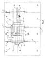
- FIG. 1 To the figure 1 is shown a plant 1 for the combustion of lean fuel gas using a burner 2 arranged between four main parts ZA, ZB, ZC, ZD separated by three walls 3, 4, 5.
- the parts represent, respectively, a combustion zone ZA where combustion is carried out, a zone ZB containing or in communication with the combustible lean gas, a zone ZC containing or in communication with combustion air, a zone ZD external to the combustion zone. installation accessible to people.
- the flammability of this gas occurs when there is 35% to 73% of gas in the mixture.
- the burner comprises a combustion nose 6 opening into zone A of the hearth; the nose is centered on a central axis X which is in this case, the main axis of the burner to the extent that it has a general shape of revolution around this axis.
- the burner also comprises supply means for this nose, which are able to eject a flow of air and fuel gas in rotation about a central axis centered on the combustion nose.
- This nose constituting the front end of the burner, is intended to receive in front of or on it, on the left of the figure, a flow of combustible gas and air combustion which is rotated about the central axis, with supply means of this nose provided for this purpose, which is described later.
- the burner also comprises a central box 7 connected to the nose and upstream of it (with respect to the direction of flow flow), arranged in the zone ZB between the walls 3 and 4, and having at least one opening 8 opening in this zone ZB.
- zone ZC In the zone ZC is a rear end 7B of the burner connected to the box 7, upstream thereof, and having at least one access for at least one combustion air inlet of the zone ZC.
- the method may comprise a first step in which a flow of air for combustion is split into at least one pre-mix air stream and a complementary air stream.
- the complementary air consists of at least one central air flow and / or a peripheral air flow.
- both the central and peripheral air flow are used for greater efficiency and flexibility of use and the split is effected by different air inlets at the rear of the burner or flow path. the air in the burner.
- the burner is configured to divide the air coming from the space ZC into several streams. It comprises several arrivals or access on its rear end: a central access 9 to receive a central air flow inlet, a peripheral access 10 to receive a peripheral air inlet, and at least a main access 10A to receive an arrival premix air. Other accesses can be added as indicated later.
- this division step could be done differently, for example by external pipes outside the burner, and each of the air flows could be brought by these independent and external pipes.
- a premix flow containing a mixture of premix air and fuel gas, rotating around the central axis, is ejected in front of the combustion nose.
- the premix stream being non-flammable to the extent that it is mixed at a rate remote from the flammability ranges, for example greater than a flammability threshold.
- a 100% lean gas rate is increased to a rate of 80-85% of gas (in the gas + air mixture) while the flammability limits are 30 to 73%. % of gas in the mixture.
- the burner in the example described, is configured to carry out premixing beforehand inside itself, in this case in a space 16 called pre-mixing of the box 7.
- This rotation is preferably also carried out in the box upstream of the combustion nose.
- the pre-mixing air accesses 10A mentioned above open into the caisson as well as the access ports 8 of fuel gas so that a premix can be carried out with the aid of mixing means 11 described later.
- the mixture is carried out at a level 5 to 20% higher than the flammability threshold with an insufficient air ratio (proportions ranging from 78 to 95% of gas in the mixture) .
- the process could be implemented by performing a premix with an insufficient fuel gas content in the same proportions of 5 to 20% or with different proportions for particular applications of bio gas or VOC burns.
- the complementary flow is ejected at the center of the premix flow through the central complementary air flow and / or around the pre-mix flow via the air flow. additional peripheral, so as to reach the flammability threshold at the combustion nose.
- the ejection of the complementary flow takes place both at the center and at the periphery so as to achieve a better final mixture.
- the burner is configured to open the crown-shaped pre-mix flow 12 located between a central pipe 13 and the periphery 14 of the front end of the box.
- the pre-mix flow is obtained by incorporating premix air into combustible gas.
- the burner comprises the incorporation means 11 mentioned above which inject air into the fuel gas.
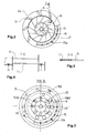
- the incorporation is carried out directly in a chamber of the box having a premix space 16 ( figure 2 ) delimited between a central pipe 13 and an inner wall 31 of the box.
- the burner may comprise injection means comprising nozzles 17 or high-flow directional calibrated orifices arranged in the profiled means of incorporation 11 and oriented towards the premix space 16 at the level of the openings 8.
- the gas located near and around the lights 8 is driven by the depression generated by the air jets at the outlet of the nozzles directed by the orientation of the jets and mixed by the turbulence of the jets.
- a rotation of the mixing is also initiated at this level in the premix space by the orientation of the air jets.
- These injection means preferably have a steady state.
- the incorporating means comprises pre-mixing air injection means arranged to realize air incorporation parallel to the central axis and directing the pre-mix flow towards the combustion nose.
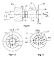
- These injection means have a progressive regime according to the power level used and can be formed, as in the illustrated example, of tubes 21 around orifices 22 in the wall 23 of the rear end of the burner ( Fig. 3 , 10, 11 ). These tubes preferably have different lengths and are five in the example. They extend inside the premix space from air inlets or orifices 22 disposed on the wall 23 or rear face of the burner.
- the orifices 22 are preferably closed by valves (not shown) operable by calibrated springs or electrical controls.
- the valves can be arranged on the orifices with or without tubes.
- the tubes make it possible, on the one hand, to prevent the respective flows from being disturbed and, on the other hand, to bring air to different points with a guarantee of its distribution.
- the orifices have a size determined so as to avoid being too massively within the flammability limits, and that there are locally favorable conditions for combustion that would deteriorate the burner.
- the central complementary air flow is ejected in rotation in front of the combustion nose and in divergent flow to penetrate the premix flow and the peripheral complementary air flow is ejected in convergent flow and in strong spiral rotation.
- the burner is configured in the example with a conical deflector 18 at the outlet of the central pipe 13 and fins 19 in the pipe which put the central air flow in rotation.
- Other equivalent means may also be suitable, for example, calibrated directional or oriented openings in a partition wall.
- the central air is divergent with an apex angle of 60 to 180 ° or 30 to 90 ° with respect to the burner axis.
- This ejection thus produced makes it possible to obtain good penetration of the air into the premix so as to best complete the missing air ratio.
- the central air flow of the example has previously penetrated the inlet 9 in the inner pipe of the pipe 13, in the annular space around the central pole 51.
- this central air may have another function explained later, which is to supply its ejection base a rich gas which would be distributed in a ring around the central air during its use during starts.
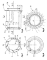
- the burner is configured with injection nozzles 20a, 20b disposed on a ring 14 of the end or front face of the box 26a.
- the nozzles are oriented both tangentially to a circle centered on the central axis and facing forward. The spiral rotation is obtained by this double inclination of the nozzles.
- peripheral air envelops the flow of lean gas and accentuates the rotation. It is distributed at high speed and optimizes the mixture.
- the nozzles 20a, 20b are fed by the peripheral pre-ejection space 30 located in a double wall of the box at the front of the box, itself fed by the arrival means 10A formed in the vicinity of the rear end 26b of the box.
- the burner box is a burner box
- nozzles are in fact exit holes formed in the ring, one of whose functions is to close the front end of the double wall of the box; the other rear end of the double wall being closed by a wall 23B.
- These holes communicate with the pre-ejection space 30 of the double wall and open out through an inner wall of the box; the nozzles are disposed on the ring being offset with respect to the radial axis R of the box and inclined forwardly relative to a plane perpendicular to the box.
- the nozzles are offset and inclined in different ways alternately.
- the proposed angles are specific to this burner power, but would inevitably be modified for another size of burner. These angles are determined so that the jets of the consecutive orifices do not disturb, and they do not come to strike the end of the tube 13 nor hinder the flow of fluids leaving the gas ring contained between 13 and 56, nor the complementary central air diverges.
- This diverging cone must almost "mesh" with the convergent peripheral complementary jet whose angle is the most closed (here 15 °). The angle of the next orifice is more open in order to continue the work of the previous orifice further in the rotation.
- a first series of nozzles (20a) can be inclined from 5 ° to 45 ° forwards, (15 ° preferred in the embodiment) and from 30 to 65 ° with respect to the radial axis (R), (44 ° preferred in the example) and a second series of nozzles (20b) inclined 25 to 65 ° forward (45 ° preferred in the example), and 30 to 70 ° relative to the axis radial (53 ° preferred in the example).
- the box may also include orifices 55 disposed on the inner wall 25 at the pre-ejection chamber 30. These orifices make it possible to feed the fin device 37 from the chamber 30 to improve the poor air / gas mixture. between the fins.
- the central tube is a central tube
- a central tube 13 intended to be mounted centered on the central axis, is dimensioned to extend longitudinally between the two ends of the box and put them in communication.
- the central pole The central pole:
- the central pole 51 is intended to be disposed in the central tube 13 and centered on the central axis.
- the burner also has a second fin device 19 disposed within and adjacent the front of the central tube.
- the fins are fixed in the example on the central pole 51 which passes through the central tube; they are intended to extend from the surface of the pole 50 to the inner wall 52 of the central tube.
- the burner may also comprise a "burning cone" 18 forming a deflector located downstream of the central tube and spaced from it so as to effect a exhaust diverging from the central air flow.
- the burning cone is disposed at the front end of the axial pole 51.
- the gas is ejected at the end of the pole at a divergent angle defined by a series of calibrated orifices 54 arranged in a ring around the conical baffle 18 which allows ejection of this gas on a maximum circumference.
- the conical baffle may be a deflector 18b having a peripheral serration 52, and having central orifices 53 opening into the conduit of the central pole.
- the burner is sized to receive, in normal operation, a complementary flow ejection at a very high speed greater than 100 m / s while the premix flow is ejected at a speed of 40 to 80 m / s.
- the burner may comprise a rich gas supply.
- the rich gas is pressurized at the periphery of the central tube directly into the premix space.
- the rich gas is distributed around the central tube so as to mix intimately with the premix.
- the tube portion 56 may extend to the end of the central tube 13 forming a central double wall 56B so as to eject the rich gas directly to the combustion nose around the central air.
- the rich gas is always brought under pressure but in the central pole. It is ejected, at a defined divergent angle, by a series of calibrated orifices 53 arranged in a ring around a particular device (deflector with peripheral serrations 52) which makes it possible to eject this gas on a maximum circumference, so that the jets Rich gas originates as close to the combustion air, and have a maximum pulse by striking the poor gas flow.
- An ignition flame is provided in front of the nose of the burner via a guide tube of the ignition burner 60 ( Fig. 1 ).
- the permanent air circuit is then activated by a pump (not shown) which blows combustion air at the rear of the burner by putting the air supply box ZC under pressure.
- a fraction of the combustion air enters the double wall 27 of the box ( Fig. 6 ) through the inlet orifices 10 for example rectangular and formed in the annular wall 23B closing the double wall on the back; while another fraction directly enters the double box to the nozzles 20a, 20b.
- the beams are pressurized and combustion air escapes from the nozzles tangentially ( Fig. 7 ) to a circle centered on the central axis and towards the fins of the first device for rotating.
- the flue gas which may be under slight pressure (generally less than (0.02 bar (200 mm CE)) enters transversely into the box under a driving effect of the air jets at the openings 8 between the beams 11 the turbulence effects premixing or stirring in the pre-mixing space 16 of the box at the inlet of the fin device ( Fig. 7 ) in particular by inflection against the inflection wall 31.
- the beams also open into the pre-ejection chamber 30 of peripheral air, they contribute to conduct air in addition to that conveyed by the interior of the double wall inflection or guide 24, 25.
- the combustion air also enters through the inlet 9 of the central tube 13 ( Fig. 10, 11 ) and opens directly at the nose 6 after having passed into the space between the fins of the second fin device 19 ( Fig. 2 ) where he takes a turning motion.
- This air spring in front of the nose divergently through the conical deflector 18 placed in front.
- the peripheral air is ejected from the chamber 30 ( fig.9 , 14-16 ) in the form of two vortices via the peripheral nozzles 20a, 20b in front of the combustion nose
- the directions of rotation of the different air flows may be contrary to that of the pre-mix flow but preferably in the same direction.
- Air can also come from the back of the box 36 through orifices 10A2 and enrich the premix.
- air can escape from the box from the pre-ejection chamber 30 through orifices 55 formed in the bottom wall of the box and penetrates radially into the fin device 37 between the fins. This improves the mixing of the gas mixture with the air.
Landscapes
- Engineering & Computer Science (AREA)
- Mechanical Engineering (AREA)
- General Engineering & Computer Science (AREA)
- Environmental & Geological Engineering (AREA)
- Chemical & Material Sciences (AREA)
- Combustion & Propulsion (AREA)
- Gas Burners (AREA)
- Pre-Mixing And Non-Premixing Gas Burner (AREA)
Priority Applications (1)
| Application Number | Priority Date | Filing Date | Title |
|---|---|---|---|
| PL06794220T PL1907754T3 (pl) | 2005-07-26 | 2006-07-26 | Sposób i instalacja do spalania ubogiego paliwa gazowego, bez wsparcia, za pomocą palnika i związany z tym palnik |
Applications Claiming Priority (2)
| Application Number | Priority Date | Filing Date | Title |
|---|---|---|---|
| FR0507964A FR2889292B1 (fr) | 2005-07-26 | 2005-07-26 | Procede et installation de combustion sans soutien de gaz combustible pauvre a l'aide d'un bruleur et bruleur associe |
| PCT/FR2006/001821 WO2007012755A1 (fr) | 2005-07-26 | 2006-07-26 | Procédé et installation de combustion de gaz combustible pauvre, sans soutien, à l'aide d'un brûleur et brûleur associé |
Publications (2)
| Publication Number | Publication Date |
|---|---|
| EP1907754A1 EP1907754A1 (fr) | 2008-04-09 |
| EP1907754B1 true EP1907754B1 (fr) | 2013-10-23 |
Family
ID=36228640
Family Applications (1)
| Application Number | Title | Priority Date | Filing Date |
|---|---|---|---|
| EP06794220.1A Not-in-force EP1907754B1 (fr) | 2005-07-26 | 2006-07-26 | Procédé et installation de combustion de gaz combustible pauvre, sans soutien, à l'aide d'un brûleur et brûleur associé |
Country Status (8)
| Country | Link |
|---|---|
| US (1) | US20080227040A1 (pl) |
| EP (1) | EP1907754B1 (pl) |
| CN (1) | CN101297160B (pl) |
| EA (1) | EA012937B1 (pl) |
| ES (1) | ES2443116T3 (pl) |
| FR (1) | FR2889292B1 (pl) |
| PL (1) | PL1907754T3 (pl) |
| WO (1) | WO2007012755A1 (pl) |
Families Citing this family (17)
| Publication number | Priority date | Publication date | Assignee | Title |
|---|---|---|---|---|
| US8555646B2 (en) * | 2009-01-27 | 2013-10-15 | General Electric Company | Annular fuel and air co-flow premixer |
| EP2233836B1 (de) | 2009-03-23 | 2015-07-29 | Siemens Aktiengesellschaft | Drallerzeuger, Verfahren zum Vermeiden von Flammenrückschlag in einem Brenner mit wenigstens einem Drallerzeuger und Brenner |
| EP2643635A1 (en) * | 2010-11-26 | 2013-10-02 | Bekaert Combustion Technology B.V. | Burner with secondary axial flow elements |
| EP2479491B1 (en) | 2011-01-20 | 2014-03-26 | Fortum OYJ | Method and burner for burning lean gas in a power plant boiler |
| FR3011911B1 (fr) | 2013-10-14 | 2015-11-20 | Cogebio | Bruleur de gaz pauvre |
| JP2017520738A (ja) | 2014-04-09 | 2017-07-27 | ゼネラル・エレクトリック・カンパニイ | 燃焼ライナの補修方法及び装置 |
| FR3030689B1 (fr) * | 2014-12-23 | 2016-12-23 | Air Liquide | Oxy-bruleur pour gaz combustible a bas pouvoir calorifique et son utilisation |
| CN106838863B (zh) * | 2016-11-29 | 2020-05-08 | 中冶南方都市环保工程技术股份有限公司 | 采用低热值煤气发电的方法 |
| EP3364105B1 (en) | 2017-02-16 | 2019-11-27 | Vysoké ucení Technické v Brne | Burner for low calorific fuels |
| CN110848667B (zh) * | 2019-09-25 | 2021-05-28 | 西安交通大学 | 一种低热值含氮燃气燃烧系统及方法 |
| CN110822417B (zh) * | 2019-10-29 | 2024-06-25 | 陕西工业职业技术学院 | 一种燃气工业锅炉全预混脱硝系统及控制方法 |
| CN111578270B (zh) * | 2020-05-26 | 2022-08-23 | 中国中材海外科技发展有限公司 | 一种水泥窑尾用低氮燃烧装置 |
| CN114088872B (zh) * | 2020-12-18 | 2024-03-08 | 北京科技大学 | 一种湍流灭火分区实验装置 |
| CN112684099B (zh) * | 2020-12-18 | 2022-09-09 | 郑州大学 | 一种组装式湍流火焰熄灭装置 |
| CN115468164A (zh) * | 2022-09-01 | 2022-12-13 | 芜湖精塑实业有限公司 | 一种低氮燃烧器 |
| CN116554928B (zh) * | 2023-05-11 | 2023-12-22 | 广州美东能源有限公司 | 一种用于替代天然气的lpg混空制备工艺 |
| CN120252031B (zh) * | 2025-05-15 | 2025-11-11 | 中山市跃龙厨房电器有限公司 | 一种设有节能型组件的灶具 |
Family Cites Families (38)
| Publication number | Priority date | Publication date | Assignee | Title |
|---|---|---|---|---|
| US3125043A (en) * | 1964-03-17 | Method of removing volatile constituents | ||
| US1779647A (en) * | 1927-11-23 | 1930-10-28 | Int Comb Eng Corp | Burner |
| US2113619A (en) * | 1934-06-15 | 1938-04-12 | Saint-Jacques Eugene Camille | Furnace for the agglomeration of pulverulent materials |
| US2120785A (en) * | 1935-03-12 | 1938-06-14 | Saint-Jacques Eugene Camille | Furnace for treating pulverulent materials |
| US2338623A (en) * | 1941-01-30 | 1944-01-04 | Crowe John Marshall | Burner structure |
| US2935127A (en) * | 1954-09-16 | 1960-05-03 | Owens Corning Fiberglass Corp | Apparatus for burning fluid combustible mixtures |
| US2952310A (en) * | 1955-02-22 | 1960-09-13 | Shell Dev | Burning of regenerator flue gas |
| US3009513A (en) * | 1956-12-24 | 1961-11-21 | Oxy Catalyst Inc | Treatment of waste gas streams |
| US3229746A (en) * | 1964-06-22 | 1966-01-18 | Foster Wheeler Corp | Heat recovery apparatus and method suitable for lean concentrations of a burnable gas |
| US3368605A (en) * | 1966-02-03 | 1968-02-13 | Zink Co John | Burner assembly for lean fuel gases |
| BE755352A (nl) * | 1969-09-05 | 1971-03-01 | Shell Int Research | Verbrandingsinrichting voor gasvormige brandstof |
| US4218426A (en) * | 1976-04-09 | 1980-08-19 | Continental Carbon Company | Method and apparatus for the combustion of waste gases |
| US4257762A (en) * | 1978-09-05 | 1981-03-24 | John Zink Company | Multi-fuel gas burner using preheated forced draft air |
| US4281983A (en) * | 1979-04-06 | 1981-08-04 | John Zink Company | Premix burner system for low BTU gas fuel |
| US4323343A (en) * | 1980-02-04 | 1982-04-06 | John Zink Company | Burner assembly for smokeless combustion of low calorific value gases |
| US4551090A (en) * | 1980-08-25 | 1985-11-05 | L. & C. Steinmuller Gmbh | Burner |
| US4402666A (en) * | 1980-12-09 | 1983-09-06 | John Zink Company | Forced draft radiant wall fuel burner |
| US4483832A (en) * | 1982-03-30 | 1984-11-20 | Phillips Petroleum Company | Recovery of heat values from vitiated gaseous mixtures |
| US4559009A (en) * | 1982-08-06 | 1985-12-17 | Hauck Manufacturing Company | Aggregate dryer burner |
| JPS6086312A (ja) * | 1983-10-19 | 1985-05-15 | Daido Steel Co Ltd | 微粉炭バ−ナ− |
| JPS6091126A (ja) * | 1983-10-25 | 1985-05-22 | Babcock Hitachi Kk | 低カロリ−ガスバ−ナ |
| US4602571A (en) * | 1984-07-30 | 1986-07-29 | Combustion Engineering, Inc. | Burner for coal slurry |
| FR2569825B1 (fr) * | 1984-09-04 | 1988-12-09 | Totalgaz Cie Fse | Bruleur a melange prealable integre et a flamme pilote integree |
| US4645449A (en) * | 1985-05-06 | 1987-02-24 | John Zink Company | Methods and apparatus for burning fuel with low nox formation |
| US4604048A (en) * | 1985-05-06 | 1986-08-05 | John Zink Company | Methods and apparatus for burning fuel with low NOx formation |
| US4725223A (en) * | 1986-09-22 | 1988-02-16 | Maxon Corporation | Incinerator burner assembly |
| US4859173A (en) * | 1987-09-28 | 1989-08-22 | Exxon Research And Engineering Company | Low BTU gas staged air burner for forced-draft service |
| US4915619A (en) * | 1988-05-05 | 1990-04-10 | The Babcock & Wilcox Company | Burner for coal, oil or gas firing |
| US4836772A (en) * | 1988-05-05 | 1989-06-06 | The Babcock & Wilcox Company | Burner for coal, oil or gas firing |
| JP2755603B2 (ja) * | 1988-07-29 | 1998-05-20 | 財団法人電力中央研究所 | ガスタービン燃焼器 |
| FR2656676B1 (fr) * | 1989-12-28 | 1994-07-01 | Inst Francais Du Petrole | Bruleur industriel a combustible liquide a faible emission d'oxyde d'azote, ledit bruleur generant plusieurs flammes elementaires et son utilisation. |
| JP2524025B2 (ja) * | 1991-09-24 | 1996-08-14 | 株式会社神戸製鋼所 | 低カロリ―ガスの燃焼バ―ナ構造およびその燃焼方法 |
| DE19627203C2 (de) * | 1996-07-05 | 2000-11-09 | Loesche Gmbh | Brenner |
| DE19736902A1 (de) * | 1997-08-25 | 1999-03-04 | Abb Research Ltd | Brenner für einen Wärmeerzeuger |
| DE59810551D1 (de) * | 1998-08-19 | 2004-02-12 | Alstom Switzerland Ltd | Brenner zum Betrieb einer Brennkammer |
| US6733278B1 (en) * | 2002-08-22 | 2004-05-11 | David P. Welden | Variable heat output burner assembly |
| AU2003253274A1 (en) * | 2003-07-25 | 2005-02-14 | Ansaldo Energia S.P.A. | Gas turbine burner |
| US8794960B2 (en) * | 2004-02-25 | 2014-08-05 | John Zink Company, Llc | Low NOx burner |
-
2005
- 2005-07-26 FR FR0507964A patent/FR2889292B1/fr not_active Expired - Fee Related
-
2006
- 2006-07-26 ES ES06794220.1T patent/ES2443116T3/es active Active
- 2006-07-26 WO PCT/FR2006/001821 patent/WO2007012755A1/fr not_active Ceased
- 2006-07-26 EA EA200800437A patent/EA012937B1/ru not_active IP Right Cessation
- 2006-07-26 CN CN2006800272090A patent/CN101297160B/zh not_active Expired - Fee Related
- 2006-07-26 US US11/996,587 patent/US20080227040A1/en not_active Abandoned
- 2006-07-26 PL PL06794220T patent/PL1907754T3/pl unknown
- 2006-07-26 EP EP06794220.1A patent/EP1907754B1/fr not_active Not-in-force
Also Published As
| Publication number | Publication date |
|---|---|
| PL1907754T3 (pl) | 2014-05-30 |
| WO2007012755A1 (fr) | 2007-02-01 |
| FR2889292B1 (fr) | 2015-01-30 |
| ES2443116T3 (es) | 2014-02-17 |
| CN101297160B (zh) | 2011-07-20 |
| FR2889292A1 (fr) | 2007-02-02 |
| EP1907754A1 (fr) | 2008-04-09 |
| US20080227040A1 (en) | 2008-09-18 |
| EA200800437A1 (ru) | 2008-08-29 |
| CN101297160A (zh) | 2008-10-29 |
| EA012937B1 (ru) | 2010-02-26 |
Similar Documents
| Publication | Publication Date | Title |
|---|---|---|
| EP1907754B1 (fr) | Procédé et installation de combustion de gaz combustible pauvre, sans soutien, à l'aide d'un brûleur et brûleur associé | |
| EP2153130B1 (fr) | Procede de combustion a bas nox pour la fusion du verre et injecteur mixte | |
| EP1144915B1 (fr) | Appareil de type torchere et procede pour la combustion de gaz | |
| FR2648184A1 (fr) | Injecteur de carburant double, notamment pour turbomoteur | |
| EP1031790B1 (fr) | Perfectionnements apportés aux brûleurs à flamme plate | |
| FR2706985A1 (pl) | ||
| WO2015055916A1 (fr) | Brûleur de gaz pauvre | |
| EP0099828A2 (fr) | Dispositif pour la combustion de fluides combustibles avec induction d'air | |
| CA2657537C (fr) | Bruleur et procede pour la mise en oeuvre alternee d'une oxycombustion et d'une aerocombustion | |
| EP3105506B1 (fr) | Module de brûleur en veine | |
| EP0926434A1 (fr) | Brûleur à faible émission d'oxyde d'azote avec circuit de gaz recyclé | |
| KR101272380B1 (ko) | 펠릿연료 연소장치 | |
| BE1024784A1 (fr) | Procédé de combustion de combustible dans une chambre de combustion tubulaire | |
| FR2804748A1 (fr) | Perfectionnement aux bruleurs a gaz pour le chauffage d'un gaz circulant dans un conduit | |
| EP3234462B1 (fr) | Dispositif de combustion comprenant une enceinte de combustion a parois dites « froides », chaudière et four comportant un tel dispositif | |
| FR2570473A1 (fr) | Perfectionnements aux bruleurs a gaz a ecoulement parallele comportant une rosace et un moyeu d'accrochage de flamme concernant les bruleurs a gaz et l'alimentation independante en air central | |
| FR2670801A1 (fr) | Dispositif d'allumage d'un lit de melange de materiaux tels que du minerai et du coke. | |
| EP2314921A2 (fr) | Procédé de fonctionnement d'une chaudière | |
| FR3066553A1 (fr) | Injecteur central a tourbillonneurs radiaux | |
| WO2025032142A1 (fr) | Bruleur, notamment pour section de prechauffage a flamme directe de ligne continue de traitement d'une bande metallique | |
| KR101457301B1 (ko) | 펠릿연료 예비연소장치 | |
| FR2685447A1 (fr) | Bruleur perfectionne a grille ainsi qu'installation de chauffage equipee d'un tel bruleur. | |
| FR2686681A1 (fr) | Bruleur industriel polycombustibles de grande puissance. | |
| FR2877074A1 (fr) | Dispositif de combustion pour ensemble comprenant une turbine a gaz et une chaudiere a recuperation | |
| BE564790A (pl) |
Legal Events
| Date | Code | Title | Description |
|---|---|---|---|
| PUAI | Public reference made under article 153(3) epc to a published international application that has entered the european phase |
Free format text: ORIGINAL CODE: 0009012 |
|
| 17P | Request for examination filed |
Effective date: 20080215 |
|
| AK | Designated contracting states |
Kind code of ref document: A1 Designated state(s): AT BE BG CH CY CZ DE DK EE ES FI FR GB GR HU IE IS IT LI LT LU LV MC NL PL PT RO SE SI SK TR |
|
| 17Q | First examination report despatched |
Effective date: 20100428 |
|
| DAX | Request for extension of the european patent (deleted) | ||
| GRAP | Despatch of communication of intention to grant a patent |
Free format text: ORIGINAL CODE: EPIDOSNIGR1 |
|
| INTG | Intention to grant announced |
Effective date: 20130605 |
|
| GRAS | Grant fee paid |
Free format text: ORIGINAL CODE: EPIDOSNIGR3 |
|
| GRAA | (expected) grant |
Free format text: ORIGINAL CODE: 0009210 |
|
| AK | Designated contracting states |
Kind code of ref document: B1 Designated state(s): AT BE BG CH CY CZ DE DK EE ES FI FR GB GR HU IE IS IT LI LT LU LV MC NL PL PT RO SE SI SK TR |
|
| REG | Reference to a national code |
Ref country code: GB Ref legal event code: FG4D Free format text: NOT ENGLISH |
|
| REG | Reference to a national code |
Ref country code: CH Ref legal event code: EP |
|
| REG | Reference to a national code |
Ref country code: AT Ref legal event code: REF Ref document number: 637815 Country of ref document: AT Kind code of ref document: T Effective date: 20131115 |
|
| REG | Reference to a national code |
Ref country code: IE Ref legal event code: FG4D Free format text: LANGUAGE OF EP DOCUMENT: FRENCH |
|
| REG | Reference to a national code |
Ref country code: DE Ref legal event code: R096 Ref document number: 602006038970 Country of ref document: DE Effective date: 20131219 |
|
| REG | Reference to a national code |
Ref country code: ES Ref legal event code: FG2A Ref document number: 2443116 Country of ref document: ES Kind code of ref document: T3 Effective date: 20140217 |
|
| REG | Reference to a national code |
Ref country code: NL Ref legal event code: VDEP Effective date: 20131023 |
|
| REG | Reference to a national code |
Ref country code: AT Ref legal event code: MK05 Ref document number: 637815 Country of ref document: AT Kind code of ref document: T Effective date: 20131023 |
|
| REG | Reference to a national code |
Ref country code: LT Ref legal event code: MG4D |
|
| PG25 | Lapsed in a contracting state [announced via postgrant information from national office to epo] |
Ref country code: NL Free format text: LAPSE BECAUSE OF FAILURE TO SUBMIT A TRANSLATION OF THE DESCRIPTION OR TO PAY THE FEE WITHIN THE PRESCRIBED TIME-LIMIT Effective date: 20131023 Ref country code: SE Free format text: LAPSE BECAUSE OF FAILURE TO SUBMIT A TRANSLATION OF THE DESCRIPTION OR TO PAY THE FEE WITHIN THE PRESCRIBED TIME-LIMIT Effective date: 20131023 Ref country code: FI Free format text: LAPSE BECAUSE OF FAILURE TO SUBMIT A TRANSLATION OF THE DESCRIPTION OR TO PAY THE FEE WITHIN THE PRESCRIBED TIME-LIMIT Effective date: 20131023 Ref country code: LT Free format text: LAPSE BECAUSE OF FAILURE TO SUBMIT A TRANSLATION OF THE DESCRIPTION OR TO PAY THE FEE WITHIN THE PRESCRIBED TIME-LIMIT Effective date: 20131023 Ref country code: IS Free format text: LAPSE BECAUSE OF FAILURE TO SUBMIT A TRANSLATION OF THE DESCRIPTION OR TO PAY THE FEE WITHIN THE PRESCRIBED TIME-LIMIT Effective date: 20140223 |
|
| PG25 | Lapsed in a contracting state [announced via postgrant information from national office to epo] |
Ref country code: AT Free format text: LAPSE BECAUSE OF FAILURE TO SUBMIT A TRANSLATION OF THE DESCRIPTION OR TO PAY THE FEE WITHIN THE PRESCRIBED TIME-LIMIT Effective date: 20131023 Ref country code: CY Free format text: LAPSE BECAUSE OF FAILURE TO SUBMIT A TRANSLATION OF THE DESCRIPTION OR TO PAY THE FEE WITHIN THE PRESCRIBED TIME-LIMIT Effective date: 20131023 Ref country code: LV Free format text: LAPSE BECAUSE OF FAILURE TO SUBMIT A TRANSLATION OF THE DESCRIPTION OR TO PAY THE FEE WITHIN THE PRESCRIBED TIME-LIMIT Effective date: 20131023 |
|
| REG | Reference to a national code |
Ref country code: PL Ref legal event code: T3 |
|
| PG25 | Lapsed in a contracting state [announced via postgrant information from national office to epo] |
Ref country code: PT Free format text: LAPSE BECAUSE OF FAILURE TO SUBMIT A TRANSLATION OF THE DESCRIPTION OR TO PAY THE FEE WITHIN THE PRESCRIBED TIME-LIMIT Effective date: 20140224 |
|
| REG | Reference to a national code |
Ref country code: DE Ref legal event code: R097 Ref document number: 602006038970 Country of ref document: DE |
|
| PG25 | Lapsed in a contracting state [announced via postgrant information from national office to epo] |
Ref country code: EE Free format text: LAPSE BECAUSE OF FAILURE TO SUBMIT A TRANSLATION OF THE DESCRIPTION OR TO PAY THE FEE WITHIN THE PRESCRIBED TIME-LIMIT Effective date: 20131023 |
|
| REG | Reference to a national code |
Ref country code: CH Ref legal event code: NV Representative=s name: MICHELI AND CIE SA, CH |
|
| PG25 | Lapsed in a contracting state [announced via postgrant information from national office to epo] |
Ref country code: SK Free format text: LAPSE BECAUSE OF FAILURE TO SUBMIT A TRANSLATION OF THE DESCRIPTION OR TO PAY THE FEE WITHIN THE PRESCRIBED TIME-LIMIT Effective date: 20131023 Ref country code: RO Free format text: LAPSE BECAUSE OF FAILURE TO SUBMIT A TRANSLATION OF THE DESCRIPTION OR TO PAY THE FEE WITHIN THE PRESCRIBED TIME-LIMIT Effective date: 20131023 |
|
| PLBE | No opposition filed within time limit |
Free format text: ORIGINAL CODE: 0009261 |
|
| STAA | Information on the status of an ep patent application or granted ep patent |
Free format text: STATUS: NO OPPOSITION FILED WITHIN TIME LIMIT |
|
| PG25 | Lapsed in a contracting state [announced via postgrant information from national office to epo] |
Ref country code: DK Free format text: LAPSE BECAUSE OF FAILURE TO SUBMIT A TRANSLATION OF THE DESCRIPTION OR TO PAY THE FEE WITHIN THE PRESCRIBED TIME-LIMIT Effective date: 20131023 |
|
| 26N | No opposition filed |
Effective date: 20140724 |
|
| REG | Reference to a national code |
Ref country code: DE Ref legal event code: R097 Ref document number: 602006038970 Country of ref document: DE Effective date: 20140724 |
|
| PG25 | Lapsed in a contracting state [announced via postgrant information from national office to epo] |
Ref country code: SI Free format text: LAPSE BECAUSE OF FAILURE TO SUBMIT A TRANSLATION OF THE DESCRIPTION OR TO PAY THE FEE WITHIN THE PRESCRIBED TIME-LIMIT Effective date: 20131023 |
|
| REG | Reference to a national code |
Ref country code: IE Ref legal event code: MM4A |
|
| PG25 | Lapsed in a contracting state [announced via postgrant information from national office to epo] |
Ref country code: IE Free format text: LAPSE BECAUSE OF NON-PAYMENT OF DUE FEES Effective date: 20140726 |
|
| PG25 | Lapsed in a contracting state [announced via postgrant information from national office to epo] |
Ref country code: BG Free format text: LAPSE BECAUSE OF FAILURE TO SUBMIT A TRANSLATION OF THE DESCRIPTION OR TO PAY THE FEE WITHIN THE PRESCRIBED TIME-LIMIT Effective date: 20131023 |
|
| REG | Reference to a national code |
Ref country code: FR Ref legal event code: PLFP Year of fee payment: 11 |
|
| PG25 | Lapsed in a contracting state [announced via postgrant information from national office to epo] |
Ref country code: GR Free format text: LAPSE BECAUSE OF FAILURE TO SUBMIT A TRANSLATION OF THE DESCRIPTION OR TO PAY THE FEE WITHIN THE PRESCRIBED TIME-LIMIT Effective date: 20140124 |
|
| PG25 | Lapsed in a contracting state [announced via postgrant information from national office to epo] |
Ref country code: TR Free format text: LAPSE BECAUSE OF FAILURE TO SUBMIT A TRANSLATION OF THE DESCRIPTION OR TO PAY THE FEE WITHIN THE PRESCRIBED TIME-LIMIT Effective date: 20131023 Ref country code: HU Free format text: LAPSE BECAUSE OF FAILURE TO SUBMIT A TRANSLATION OF THE DESCRIPTION OR TO PAY THE FEE WITHIN THE PRESCRIBED TIME-LIMIT; INVALID AB INITIO Effective date: 20060726 |
|
| REG | Reference to a national code |
Ref country code: FR Ref legal event code: PLFP Year of fee payment: 12 |
|
| PGFP | Annual fee paid to national office [announced via postgrant information from national office to epo] |
Ref country code: LU Payment date: 20170725 Year of fee payment: 12 |
|
| PGFP | Annual fee paid to national office [announced via postgrant information from national office to epo] |
Ref country code: RO Payment date: 20170503 Year of fee payment: 7 Ref country code: CZ Payment date: 20170720 Year of fee payment: 12 Ref country code: DE Payment date: 20170727 Year of fee payment: 12 Ref country code: ES Payment date: 20170801 Year of fee payment: 12 Ref country code: IT Payment date: 20170725 Year of fee payment: 12 Ref country code: MC Payment date: 20170706 Year of fee payment: 12 Ref country code: CH Payment date: 20170727 Year of fee payment: 12 |
|
| PGFP | Annual fee paid to national office [announced via postgrant information from national office to epo] |
Ref country code: PL Payment date: 20170706 Year of fee payment: 12 Ref country code: BE Payment date: 20170727 Year of fee payment: 12 |
|
| REG | Reference to a national code |
Ref country code: FR Ref legal event code: PLFP Year of fee payment: 13 |
|
| PGFP | Annual fee paid to national office [announced via postgrant information from national office to epo] |
Ref country code: FR Payment date: 20180726 Year of fee payment: 13 |
|
| REG | Reference to a national code |
Ref country code: DE Ref legal event code: R119 Ref document number: 602006038970 Country of ref document: DE |
|
| REG | Reference to a national code |
Ref country code: CH Ref legal event code: PL |
|
| GBPC | Gb: european patent ceased through non-payment of renewal fee |
Effective date: 20180726 |
|
| PG25 | Lapsed in a contracting state [announced via postgrant information from national office to epo] |
Ref country code: MC Free format text: LAPSE BECAUSE OF NON-PAYMENT OF DUE FEES Effective date: 20180731 Ref country code: LU Free format text: LAPSE BECAUSE OF NON-PAYMENT OF DUE FEES Effective date: 20180726 |
|
| REG | Reference to a national code |
Ref country code: BE Ref legal event code: MM Effective date: 20180731 |
|
| PG25 | Lapsed in a contracting state [announced via postgrant information from national office to epo] |
Ref country code: CZ Free format text: LAPSE BECAUSE OF NON-PAYMENT OF DUE FEES Effective date: 20180726 Ref country code: CH Free format text: LAPSE BECAUSE OF NON-PAYMENT OF DUE FEES Effective date: 20180731 Ref country code: DE Free format text: LAPSE BECAUSE OF NON-PAYMENT OF DUE FEES Effective date: 20190201 Ref country code: GB Free format text: LAPSE BECAUSE OF NON-PAYMENT OF DUE FEES Effective date: 20180726 Ref country code: LI Free format text: LAPSE BECAUSE OF NON-PAYMENT OF DUE FEES Effective date: 20180731 |
|
| PG25 | Lapsed in a contracting state [announced via postgrant information from national office to epo] |
Ref country code: BE Free format text: LAPSE BECAUSE OF NON-PAYMENT OF DUE FEES Effective date: 20180731 |
|
| PG25 | Lapsed in a contracting state [announced via postgrant information from national office to epo] |
Ref country code: IT Free format text: LAPSE BECAUSE OF NON-PAYMENT OF DUE FEES Effective date: 20180726 |
|
| REG | Reference to a national code |
Ref country code: ES Ref legal event code: FD2A Effective date: 20190917 |
|
| PG25 | Lapsed in a contracting state [announced via postgrant information from national office to epo] |
Ref country code: ES Free format text: LAPSE BECAUSE OF NON-PAYMENT OF DUE FEES Effective date: 20180727 |
|
| PG25 | Lapsed in a contracting state [announced via postgrant information from national office to epo] |
Ref country code: PL Free format text: LAPSE BECAUSE OF NON-PAYMENT OF DUE FEES Effective date: 20180726 |
|
| PG25 | Lapsed in a contracting state [announced via postgrant information from national office to epo] |
Ref country code: FR Free format text: LAPSE BECAUSE OF NON-PAYMENT OF DUE FEES Effective date: 20190731 |