EP1907671B1 - Gasturbinenschaufelkranz - Google Patents
Gasturbinenschaufelkranz Download PDFInfo
- Publication number
- EP1907671B1 EP1907671B1 EP06764202A EP06764202A EP1907671B1 EP 1907671 B1 EP1907671 B1 EP 1907671B1 EP 06764202 A EP06764202 A EP 06764202A EP 06764202 A EP06764202 A EP 06764202A EP 1907671 B1 EP1907671 B1 EP 1907671B1
- Authority
- EP
- European Patent Office
- Prior art keywords
- platform
- blade
- gas turbine
- vane
- root
- Prior art date
- Legal status (The legal status is an assumption and is not a legal conclusion. Google has not performed a legal analysis and makes no representation as to the accuracy of the status listed.)
- Not-in-force
Links
- 239000000919 ceramic Substances 0.000 claims description 4
- 238000001816 cooling Methods 0.000 description 6
- 238000002485 combustion reaction Methods 0.000 description 5
- 206010016256 fatigue Diseases 0.000 description 4
- 230000000694 effects Effects 0.000 description 3
- 230000035508 accumulation Effects 0.000 description 2
- 238000009825 accumulation Methods 0.000 description 2
- 239000000463 material Substances 0.000 description 2
- 230000007704 transition Effects 0.000 description 2
- 238000005260 corrosion Methods 0.000 description 1
- 230000007797 corrosion Effects 0.000 description 1
- 230000003111 delayed effect Effects 0.000 description 1
- 238000009826 distribution Methods 0.000 description 1
- 230000014759 maintenance of location Effects 0.000 description 1
- 238000004519 manufacturing process Methods 0.000 description 1
- 229940028444 muse Drugs 0.000 description 1
- GMVPRGQOIOIIMI-DWKJAMRDSA-N prostaglandin E1 Chemical compound CCCCC[C@H](O)\C=C\[C@H]1[C@H](O)CC(=O)[C@@H]1CCCCCCC(O)=O GMVPRGQOIOIIMI-DWKJAMRDSA-N 0.000 description 1
- 208000024891 symptom Diseases 0.000 description 1
- 239000012720 thermal barrier coating Substances 0.000 description 1
- 230000000930 thermomechanical effect Effects 0.000 description 1
- 238000009827 uniform distribution Methods 0.000 description 1
- 238000011144 upstream manufacturing Methods 0.000 description 1
Images


Classifications
-
- F—MECHANICAL ENGINEERING; LIGHTING; HEATING; WEAPONS; BLASTING
- F01—MACHINES OR ENGINES IN GENERAL; ENGINE PLANTS IN GENERAL; STEAM ENGINES
- F01D—NON-POSITIVE DISPLACEMENT MACHINES OR ENGINES, e.g. STEAM TURBINES
- F01D5/00—Blades; Blade-carrying members; Heating, heat-insulating, cooling or antivibration means on the blades or the members
- F01D5/30—Fixing blades to rotors; Blade roots ; Blade spacers
- F01D5/3007—Fixing blades to rotors; Blade roots ; Blade spacers of axial insertion type
-
- F—MECHANICAL ENGINEERING; LIGHTING; HEATING; WEAPONS; BLASTING
- F01—MACHINES OR ENGINES IN GENERAL; ENGINE PLANTS IN GENERAL; STEAM ENGINES
- F01D—NON-POSITIVE DISPLACEMENT MACHINES OR ENGINES, e.g. STEAM TURBINES
- F01D11/00—Preventing or minimising internal leakage of working-fluid, e.g. between stages
- F01D11/005—Sealing means between non relatively rotating elements
- F01D11/006—Sealing the gap between rotor blades or blades and rotor
- F01D11/008—Sealing the gap between rotor blades or blades and rotor by spacer elements between the blades, e.g. independent interblade platforms
-
- F—MECHANICAL ENGINEERING; LIGHTING; HEATING; WEAPONS; BLASTING
- F05—INDEXING SCHEMES RELATING TO ENGINES OR PUMPS IN VARIOUS SUBCLASSES OF CLASSES F01-F04
- F05D—INDEXING SCHEME FOR ASPECTS RELATING TO NON-POSITIVE-DISPLACEMENT MACHINES OR ENGINES, GAS-TURBINES OR JET-PROPULSION PLANTS
- F05D2240/00—Components
- F05D2240/80—Platforms for stationary or moving blades
-
- F—MECHANICAL ENGINEERING; LIGHTING; HEATING; WEAPONS; BLASTING
- F05—INDEXING SCHEMES RELATING TO ENGINES OR PUMPS IN VARIOUS SUBCLASSES OF CLASSES F01-F04
- F05D—INDEXING SCHEME FOR ASPECTS RELATING TO NON-POSITIVE-DISPLACEMENT MACHINES OR ENGINES, GAS-TURBINES OR JET-PROPULSION PLANTS
- F05D2250/00—Geometry
- F05D2250/70—Shape
- F05D2250/71—Shape curved
- F05D2250/711—Shape curved convex
-
- F—MECHANICAL ENGINEERING; LIGHTING; HEATING; WEAPONS; BLASTING
- F05—INDEXING SCHEMES RELATING TO ENGINES OR PUMPS IN VARIOUS SUBCLASSES OF CLASSES F01-F04
- F05D—INDEXING SCHEME FOR ASPECTS RELATING TO NON-POSITIVE-DISPLACEMENT MACHINES OR ENGINES, GAS-TURBINES OR JET-PROPULSION PLANTS
- F05D2250/00—Geometry
- F05D2250/70—Shape
- F05D2250/71—Shape curved
- F05D2250/712—Shape curved concave
Definitions
- the invention relates to a gas turbine blade having a profiled in cross-section blade root, followed successively by a platform and thereon a longitudinally curved blade profile, wherein the blade root extends in the longitudinal direction of the blade profile and the platform has two longitudinally extending curved longitudinal platform edges.
- the invention relates to a platform element for a gas turbine blade ring of a gas turbine, with a profiled platform foot and a platform plate having two curved longitudinal edges and in which the platform plate and the platform foot extend in a longitudinal direction.
- the invention relates to a support structure for mounting arranged in a ring gas turbine blades, in which blade holding grooves are provided, in each of which the blade root of the gas turbine blade can be inserted.
- the invention relates to a gas turbine blade ring for a gas turbine having a support structure and with gas turbine blades and the use of such a gas turbine blade ring.
- Gas turbine blades with straight blade roots and platforms as well as curved blade profiles are known from the prior art.
- the pressure-side and suction-side platforms run with widely varying platform overhangs.
- platform overhangs For example, on the pressure side, in the middle region between leading edge and trailing edge, such gas turbine blades on large overhangs, which are steadily smaller towards the trailing edge and leading edge. These large overhangs are poorly coolable and reduce the fatigue life of the gas turbine blade.
- a turbine blade assembly for a gas turbine known.
- the gas turbine blade having a straight blade root is positively inserted in a retaining groove provided on the outer circumference of a turbine disk.
- the gas turbine blades only have platform stubs whose longitudinal edges are curved in the axial direction of the turbine. Between two adjacent gas turbine blades, a separate platform is connected to the turbine disk by means of an additional support. Due to the comparatively lightweight, because platformless gas turbine blade radial extension of the blade profiles is possible.
- each platform element by means of a separate holding element or a separate holder to be attached to the turbine disk muse.
- Another turbine blade assembly is of the WO 01/59263 known.
- the object of the invention is to specify a simplified system for fastening gas turbine blades and platform elements to a support structure for forming a gas turbine blade ring for a gas turbine.
- the object directed to the system is achieved by providing a gas turbine blade ring with the features of claim 1.
- the simplified system is composed at least of a support structure with axially curved retaining grooves, are fixed to the gas turbine blades with analogous to the retaining grooves curved blade roots.
- the system includes further retaining grooves in the support structure for attachment of Platform elements with correspondingly convex or concave curved longitudinal edges.
- the gas turbine blades are mounted in the support structure to a gas turbine blade ring.
- vane holding grooves are provided into which the vane feet of the gas turbine blade are insertable, the vane holding grooves corresponding to the vane roots of the gas turbine blades, i. H.
- Each blade retaining groove is curved (curved) in the longitudinal direction or in the axial direction in the same way as the blade root and profiled in cross-section.
- platform elements are mounted in the same manner as the gas turbine blade. Due to the use of approximately platformless gas turbine blades in the support structure, in each case a platform retention groove is provided in the support structure between two adjacent blade retaining grooves, which are arched to an identical extent as the platform feet. In this platform holding grooves, the platform elements are inserted in a direction of their curvature corresponding movement direction, since both the longitudinal edges of the platform elements and the platform longitudinal edges of the platform of the gas turbine blade and their (platform and blade) feet are curved in the same direction.
- a particularly small platform of the gas turbine blade is achieved in that the suction-side and / or pressure-side platform overhang is designed as a platform stub with a comparatively short platform width.
- the gas turbine blade is almost platformless, which significantly simplifies their structural design.
- the simplification leads to a cost reduction in the design of the gas turbine blade and in their manufacture.
- the invention is based on the recognition that the platform base and the blade root of the gas turbine blade as well as their retaining grooves of the support structure must be similarly shaped in the longitudinal direction or axial direction in order to achieve a particularly simple, even individual assembly.
- the platform longitudinal edges are curved in the axial direction
- the blade root extends in a straight line in the axial direction. Since the gas turbine blade thereof known is inserted in a purely translational movement due to the rectilinear blade root, and whose platform longitudinal edges are curved, the intermediate platform elements must be radially introduced into their operating position, then with an additional, mounted in a rectilinear direction of movement bracket on the rotor disk to be attached.
- the platform foot is now shaped such that it runs convexly or concavely in accordance with the platform longitudinal edges. All geometric surfaces influencing the assembly are then curved in the same direction, so that all components forming the gas turbine blade ring can be individually assembled in a direction of movement corresponding to their curvature.
- Compliance with this geometric condition also allows the provision of gas turbine blades with a pressure-side platform and a suction-side platform, each along the profile wall has an approximately equal platform width as a platform overhang.
- the platform width is the distance from the pressure-side or suction-side profile wall to the nearest platform longitudinal edge.
- the almost constant platform width allows one much easier and more efficient cooling of the platform. This results in a more uniform distribution of temperature along the platform during use in a gas turbine, which in turn prolongs the life of the gas turbine due to lower material stresses.
- the gas turbine blade according to the invention has a blade root surface on which all curvature lines extending in the longitudinal direction extend parallel to the curved platform longitudinal edges on a circular arc.
- the suction-side and the pressure-side blade root surfaces could also be curved in such a way that the blade root becomes sharpened from an oncoming-edged end face to a downstream-edged end face, i. wedge-shaped shrinking its cross section in the longitudinal direction, tapers.
- such a gas turbine blade would be pressed into a correspondingly shaped retaining a support structure due to the thrust forces occurring in the hot gas and axially fixed.
- a suction-side or pressure-side platform projection projects from the suction-side profile wall to the suction-side platform longitudinal edge and / or from the pressure-side profile wall to the pressure-side platform longitudinal edge, whose platform width is approximately constant over 30% of its longitudinal length. Due to the almost constant platform width, the transition of platform and blade profile is in operation more uniform thermal and mechanical stresses. Such a designed platform is particularly good and uniformly cool and avoids non-uniform, because substantially different width wide platform projections along the blade profile. In addition, due to the now uniformized stresses, an increase in the fatigue life can be achieved.
- the gas turbine blade is designed as a gas turbine blade, the blade root is formed in cross-section dovetailed, hammer-shaped or fir-tree-like.
- the preferably cast gas turbine blade is coolable.
- the platform foot is shaped in the longitudinal direction in such a way that all the longitudinally extending curvature lines of the platform foot surface extend parallel to the longitudinal edges on a circular arc.
- the platform foot is thus curved to the same extent as the blade root of the gas turbine blade. Both feet thus have identical circular arcs or radii, so that each element can be mounted individually in the support structure.
- this consists at least partially of ceramic.
- the platform cooling can be reduced thereby, which has an efficiency-enhancing effect on a gas turbine equipped therewith.
- the support structure is designed as a rotor disk, in which the blade retaining grooves are provided in the axial direction of the rotor disk extending in its outer periphery.
- the upstream and / or pressure-side platform or their overhangs Due to the approximately constant width of the upstream and / or pressure-side platform or their overhangs, they can be cooled easier and more efficiently.
- the use of Cooling air can be reduced.
- the saved cooling air can be supplied in the stationary gas turbine to increase the efficiency of the combustion.
- the platform element is provided as a ceramic or with a ceramic thermal barrier coating, it may even be possible to dispense with the platform cooling, which has an efficiency-increasing effect on a gas turbine equipped therewith.
- FIG. 1 shows a gas turbine 1 in a longitudinal partial section. It has inside a rotatably mounted about a rotation axis 2 rotor 3, which is also referred to as a turbine runner. Along the rotor 3 successive an intake 4, a compressor 5, a toroidal annular combustion chamber 6 with a plurality of rotationally symmetrical to each other arranged burners 7, a turbine unit 8 and an exhaust housing 9.
- the annular combustion chamber 6 forms a combustion chamber 17 which communicates with an annular hot gas channel 18.
- There four successive turbine stages 10 form the turbine unit 8. Each turbine stage 10 is formed of two blade rings.
- one row of guide vanes 13 follows one out Gas turbine blades 15 formed row 14.
- the vanes 12 are attached to the stator, whereas the gas turbine blades 15 of a row 14 are mounted by means of a turbine disk 19 on the rotor 3.
- a generator or a working machine (not shown) is coupled.
- FIG. 2 shows a gas turbine blade according to the invention designed as a gas turbine blade 50 with a blade root 52, on which a platform 54 and a blade profile 56 is successively provided.
- the blade profile 56 is curved in the longitudinal direction L, ie in the installed position in a gas turbine 1 in the axial direction A.
- the blade profile 56 is not shown in its full height, but it ends comparatively close to the platform 54th
- the blade profile 56 has a pressure-side profile wall 62 and a suction-side profile wall 64, which extend from a front edge 66 of the blade profile 56 to a trailing edge 68.
- the hot gas 11 flows around the gas turbine blade 50. It flows along the profile walls 62, 64, from the front edge 66 in the direction of the trailing edge 68.
- the platform 54 is curved along the longitudinal direction L, the longitudinal edges 55 of the platform 54 do not run in a straight line but on an arc.
- the suction side platform longitudinal edge 55a is convex and the pressure side platform longitudinal edge 55b is concavely curved.
- the platform 54 has, in each case in the region of the front edge 66 and in the region of the rear edge 68, a cross-platform transverse edge 53 running transversely on the front side.
- the blade root 52 is curved in the same manner as the longitudinal edges 55 of the platform 54.
- the suction-side blade root surface 72b is longitudinal curved convexly and the pressure-side blade root surface 72a in the longitudinal direction concave.
- the blade root 52 is also shaped in the embodiment shown in such a way that all extending in the longitudinal direction L lines of curvature 70 of Schaufelfußober Design 72 extend parallel to the platform longitudinal edge 55 on a circular arc.
- the curved lines 70 of the platform longitudinal edges 55 and of the blade root 52 can run on a circular arc, so that they are particularly easy to insert into a support structure 80 (FIG. FIG. 4 ) can be successively inserted into blade holding grooves 82.
- thermomechanical tension reducing platform overhangs 75 that extend approximately uniformly along the longitudinal axis L over at least 30% of the length of the platform 54 (longitudinally), both on the suction side and on the pressure side.
- An inventive platform element 74 is in a perspective view in FIG FIG. 3 shown.
- the platform element 74 has a platform plate 76 and a platform foot 78, both of which extend in the longitudinal direction L.
- the platform plate 76 of the platform element 74 has a platform longitudinal edge 79a that is convexly curved in the longitudinal direction L, and a concavely curved platform longitudinal edge 79b.
- the platform foot 78 is curved to the platform longitudinal edges 79 in the longitudinal direction L correspondingly.
- Like all longitudinally L extending curvature lines 70 of the Schaufelfußober Design 72 of the gas turbine blade 50 according to the invention all extend in the longitudinal direction L.
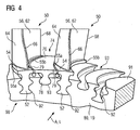
- FIG. 4 shows a perspective view of a section of a gas turbine blade ring 90 according to the invention for a gas turbine 1.
- the gas turbine blade ring 90 is held by a support structure 80, in particular a rotor disk 19.
- a support structure 80 in particular a rotor disk 19.
- profiled retaining grooves are provided in the axial direction A, relative to the axis of rotation of the rotor 3.
- the retaining grooves serve to receive and secure gas turbine blades 50 and platform elements 74 according to the present invention.
- the retaining grooves provided for attaching gas turbine blades 50 have the blade retaining grooves 92 profiled in a fir-tree cross section, whereas the platform retaining grooves 93 provided for holding and securing platform elements 74 are dovetail-shaped in cross-section are formed or may have other foot shapes.
- Each blade root 52 is seated in the blade retaining groove 92 in a positive fit, as well as each platform root 78 in the platform retaining groove 93.
- Both the blade retaining grooves 92 and the platform retaining grooves 93 are curved in the axial direction A in such a way that their axial direction A extending curvature lines of the groove surface run parallel on a circular arc and thereby correspond to the curvature of the blade root 52 and the platform foot 78.
- a more consistent platform width can generally be provided on both sides of the blade profile, i. on the suction side and on the pressure side.
- the pressure-side as well as the suction-side platform overhangs can thus be approximately the same size and thus comparatively symmetrical, which avoids one-sided platform overhangs and correspondingly locally varying mass accumulations. Varying mass accumulations have a negative effect on the voltage distributions and thus on the service life of the gas turbine blade.
- the unilaterally occurring in sections platform overhangs are difficult to cool, which also has a negative impact on the life of the gas turbine blade. Fatigue symptoms appear delayed.
- the design with curved blade root and curved platform longitudinal edges can be a design simplification of the gas turbine blade and thus a more efficient cooling brought about, which advantageously also allows the introduction of provided between the gas turbine blades platform elements or intermediate platforms.
Landscapes
- Engineering & Computer Science (AREA)
- Mechanical Engineering (AREA)
- General Engineering & Computer Science (AREA)
- Turbine Rotor Nozzle Sealing (AREA)
- Engine Equipment That Uses Special Cycles (AREA)
- Low-Molecular Organic Synthesis Reactions Using Catalysts (AREA)
Priority Applications (1)
| Application Number | Priority Date | Filing Date | Title |
|---|---|---|---|
| PL06764202T PL1907671T3 (pl) | 2005-07-25 | 2006-07-19 | Wieniec łopatkowy turbiny gazowej |
Applications Claiming Priority (3)
| Application Number | Priority Date | Filing Date | Title |
|---|---|---|---|
| US70235805P | 2005-07-25 | 2005-07-25 | |
| US11/214,303 US7300253B2 (en) | 2005-07-25 | 2005-08-29 | Gas turbine blade or vane and platform element for a gas turbine blade or vane ring of a gas turbine, supporting structure for securing gas turbine blades or vanes arranged in a ring, gas turbine blade or vane ring and the use of a gas turbine blade or vane ring |
| PCT/EP2006/064400 WO2007012587A1 (de) | 2005-07-25 | 2006-07-19 | Gasturbinenschaufel und plattformelement für einen gasturbinenschaufelkranz, tragstruktur zu deren befestigung, gasturbinenschaufelkranz und seine verwendung |
Publications (2)
| Publication Number | Publication Date |
|---|---|
| EP1907671A1 EP1907671A1 (de) | 2008-04-09 |
| EP1907671B1 true EP1907671B1 (de) | 2008-12-31 |
Family
ID=37054737
Family Applications (1)
| Application Number | Title | Priority Date | Filing Date |
|---|---|---|---|
| EP06764202A Not-in-force EP1907671B1 (de) | 2005-07-25 | 2006-07-19 | Gasturbinenschaufelkranz |
Country Status (9)
| Country | Link |
|---|---|
| US (1) | US7300253B2 (pl) |
| EP (1) | EP1907671B1 (pl) |
| JP (1) | JP2009503330A (pl) |
| CN (1) | CN101233299B (pl) |
| AT (1) | ATE419451T1 (pl) |
| DE (1) | DE502006002518D1 (pl) |
| ES (1) | ES2317560T3 (pl) |
| PL (1) | PL1907671T3 (pl) |
| WO (1) | WO2007012587A1 (pl) |
Cited By (1)
| Publication number | Priority date | Publication date | Assignee | Title |
|---|---|---|---|---|
| US9482099B2 (en) | 2010-01-16 | 2016-11-01 | Mtu Aero Engines Gmbh | Rotor blade for a turbomachine and turbomachine |
Families Citing this family (45)
| Publication number | Priority date | Publication date | Assignee | Title |
|---|---|---|---|---|
| US7931442B1 (en) * | 2007-05-31 | 2011-04-26 | Florida Turbine Technologies, Inc. | Rotor blade assembly with de-coupled composite platform |
| US8408874B2 (en) * | 2008-04-11 | 2013-04-02 | United Technologies Corporation | Platformless turbine blade |
| CH700001A1 (de) | 2008-11-20 | 2010-05-31 | Alstom Technology Ltd | Laufschaufelanordnung, insbesondere für eine gasturbine. |
| US8235663B2 (en) * | 2008-12-11 | 2012-08-07 | General Electric Company | Article and ultrasonic inspection method and system therefor |
| US20100166561A1 (en) * | 2008-12-30 | 2010-07-01 | General Electric Company | Turbine blade root configurations |
| US8277190B2 (en) * | 2009-03-27 | 2012-10-02 | General Electric Company | Turbomachine rotor assembly and method |
| US8192166B2 (en) * | 2009-05-12 | 2012-06-05 | Siemens Energy, Inc. | Tip shrouded turbine blade with sealing rail having non-uniform thickness |
| US8322977B2 (en) * | 2009-07-22 | 2012-12-04 | Siemens Energy, Inc. | Seal structure for preventing leakage of gases across a gap between two components in a turbine engine |
| US8292583B2 (en) * | 2009-08-13 | 2012-10-23 | Siemens Energy, Inc. | Turbine blade having a constant thickness airfoil skin |
| US8356975B2 (en) * | 2010-03-23 | 2013-01-22 | United Technologies Corporation | Gas turbine engine with non-axisymmetric surface contoured vane platform |
| US9976433B2 (en) | 2010-04-02 | 2018-05-22 | United Technologies Corporation | Gas turbine engine with non-axisymmetric surface contoured rotor blade platform |
| US8657579B2 (en) | 2010-08-27 | 2014-02-25 | General Electric Company | Blade for use with a rotary machine and method of assembling same rotary machine |
| US8527241B2 (en) | 2011-02-01 | 2013-09-03 | Siemens Energy, Inc. | Wireless telemetry system for a turbine engine |
| US8599082B2 (en) | 2011-02-01 | 2013-12-03 | Siemens Energy, Inc. | Bracket assembly for a wireless telemetry component |
| CH704825A1 (de) * | 2011-03-31 | 2012-10-15 | Alstom Technology Ltd | Turbomaschinenrotor. |
| US8827643B2 (en) * | 2011-10-26 | 2014-09-09 | General Electric Company | Turbine bucket platform leading edge scalloping for performance and secondary flow and related method |
| US8967973B2 (en) * | 2011-10-26 | 2015-03-03 | General Electric Company | Turbine bucket platform shaping for gas temperature control and related method |
| US9303531B2 (en) | 2011-12-09 | 2016-04-05 | General Electric Company | Quick engine change assembly for outlet guide vanes |
| US20130149127A1 (en) * | 2011-12-09 | 2013-06-13 | General Electric Company | Structural Platforms for Fan Double Outlet Guide Vane |
| US9303520B2 (en) | 2011-12-09 | 2016-04-05 | General Electric Company | Double fan outlet guide vane with structural platforms |
| US9033669B2 (en) | 2012-06-15 | 2015-05-19 | General Electric Company | Rotating airfoil component with platform having a recessed surface region therein |
| FR2994211B1 (fr) * | 2012-08-03 | 2018-03-30 | Safran Aircraft Engines | Aube mobile de turbine |
| EP2971523B1 (en) * | 2013-03-10 | 2018-11-14 | Rolls-Royce Corporation | Attachment feature of a gas turbine engine blade having a curved profile |
| EP2971736B1 (en) | 2013-03-13 | 2019-07-10 | Rolls-Royce Corporation | Interblade metal platform for ceramic matrix composite turbine blades |
| WO2014204542A2 (en) * | 2013-04-01 | 2014-12-24 | United Technologies Corporation | Lightweight blade for gas turbine engine |
| US9670781B2 (en) * | 2013-09-17 | 2017-06-06 | Honeywell International Inc. | Gas turbine engines with turbine rotor blades having improved platform edges |
| US9896946B2 (en) * | 2013-10-31 | 2018-02-20 | General Electric Company | Gas turbine engine rotor assembly and method of assembling the same |
| FR3014942B1 (fr) * | 2013-12-18 | 2016-01-08 | Snecma | Aube, roue a aubes et turbomachine ; procede de fabrication de l'aube |
| FR3018849B1 (fr) * | 2014-03-24 | 2018-03-16 | Safran Aircraft Engines | Piece de revolution pour un rotor de turbomachine |
| EP3303773B1 (en) * | 2015-06-02 | 2019-03-27 | Siemens Aktiengesellschaft | Attachment system for a turbine airfoil usable in a gas turbine engine |
| FR3048719B1 (fr) * | 2016-03-14 | 2018-03-02 | Safran Aircraft Engines | Redresseur de flux pour turbomachine avec plateformes integrees et rapportees |
| US10428661B2 (en) | 2016-10-26 | 2019-10-01 | Roll-Royce North American Technologies Inc. | Turbine wheel assembly with ceramic matrix composite components |
| US10358922B2 (en) * | 2016-11-10 | 2019-07-23 | Rolls-Royce Corporation | Turbine wheel with circumferentially-installed inter-blade heat shields |
| US10557350B2 (en) * | 2017-03-30 | 2020-02-11 | General Electric Company | I beam blade platform |
| FR3066531B1 (fr) * | 2017-05-19 | 2019-05-03 | Safran Aircraft Engines | Aube en materiau composite et a plateforme integree pour une turbomachine d'aeronef |
| US10724390B2 (en) | 2018-03-16 | 2020-07-28 | General Electric Company | Collar support assembly for airfoils |
| US10767498B2 (en) | 2018-04-03 | 2020-09-08 | Rolls-Royce High Temperature Composites Inc. | Turbine disk with pinned platforms |
| US10890081B2 (en) | 2018-04-23 | 2021-01-12 | Rolls-Royce Corporation | Turbine disk with platforms coupled to disk |
| US10577961B2 (en) | 2018-04-23 | 2020-03-03 | Rolls-Royce High Temperature Composites Inc. | Turbine disk with blade supported platforms |
| FR3085992B1 (fr) | 2018-09-14 | 2020-12-11 | Safran Aircraft Engines | Aube de roue mobile de turbine comportant un pied de forme curviligne |
| DE102020216436A1 (de) * | 2020-12-21 | 2022-06-23 | MTU Aero Engines AG | Rotorscheibe und Laufschaufel für eine Flugtriebwerk-Gasturbinen-Verdichter- oder Turbinenstufe |
| FR3130907B1 (fr) * | 2021-12-17 | 2023-11-10 | Safran Aircraft Engines | Rotor de turbine et plateforme pour un tel rotor. |
| CN116537888A (zh) * | 2022-01-25 | 2023-08-04 | 中国联合重型燃气轮机技术有限公司 | 透平静叶、透平静叶环、透平和燃气轮机 |
| FR3140649B1 (fr) * | 2022-10-07 | 2025-04-11 | Safran Aircraft Engines | Disque pour une turbine de turbomachine d’aeronef |
| US12352175B2 (en) * | 2023-07-04 | 2025-07-08 | Rolls-Royce Plc | Annulus filler for a gas turbine engine |
Family Cites Families (13)
| Publication number | Priority date | Publication date | Assignee | Title |
|---|---|---|---|---|
| US1719415A (en) * | 1927-09-14 | 1929-07-02 | Westinghouse Electric & Mfg Co | Turbine-blade attachment |
| US1793468A (en) * | 1929-05-28 | 1931-02-24 | Westinghouse Electric & Mfg Co | Turbine blade |
| US2669383A (en) * | 1951-02-06 | 1954-02-16 | A V Roe Canada Ltd | Rotor blade |
| US3986793A (en) * | 1974-10-29 | 1976-10-19 | Westinghouse Electric Corporation | Turbine rotating blade |
| US4767275A (en) * | 1986-07-11 | 1988-08-30 | Westinghouse Electric Corp. | Locking pin system for turbine curved root side entry closing blades |
| JP2506577Y2 (ja) * | 1989-08-22 | 1996-08-14 | 石川島播磨重工業株式会社 | プラットフォ―ム付圧縮機用動翼 |
| US5017091A (en) * | 1990-02-26 | 1991-05-21 | Westinghouse Electric Corp. | Free standing blade for use in low pressure steam turbine |
| GB2280478A (en) * | 1993-07-31 | 1995-02-01 | Rolls Royce Plc | Gas turbine sealing assemblies. |
| FR2715968B1 (fr) * | 1994-02-10 | 1996-03-29 | Snecma | Rotor à plates-formes rapportées entre les aubes. |
| US5435693A (en) * | 1994-02-18 | 1995-07-25 | Solar Turbines Incorporated | Pin and roller attachment system for ceramic blades |
| JP4502517B2 (ja) * | 1999-03-24 | 2010-07-14 | シーメンス アクチエンゲゼルシヤフト | 流体機械の案内羽根及び案内羽根リング |
| EP1124038A1 (de) | 2000-02-09 | 2001-08-16 | Siemens Aktiengesellschaft | Turbinenschaufelanordnung |
| US6739837B2 (en) * | 2002-04-16 | 2004-05-25 | United Technologies Corporation | Bladed rotor with a tiered blade to hub interface |
-
2005
- 2005-08-29 US US11/214,303 patent/US7300253B2/en not_active Expired - Fee Related
-
2006
- 2006-07-19 CN CN2006800273303A patent/CN101233299B/zh not_active Expired - Fee Related
- 2006-07-19 PL PL06764202T patent/PL1907671T3/pl unknown
- 2006-07-19 WO PCT/EP2006/064400 patent/WO2007012587A1/de not_active Ceased
- 2006-07-19 ES ES06764202T patent/ES2317560T3/es active Active
- 2006-07-19 AT AT06764202T patent/ATE419451T1/de not_active IP Right Cessation
- 2006-07-19 JP JP2008523322A patent/JP2009503330A/ja active Pending
- 2006-07-19 DE DE502006002518T patent/DE502006002518D1/de active Active
- 2006-07-19 EP EP06764202A patent/EP1907671B1/de not_active Not-in-force
Cited By (1)
| Publication number | Priority date | Publication date | Assignee | Title |
|---|---|---|---|---|
| US9482099B2 (en) | 2010-01-16 | 2016-11-01 | Mtu Aero Engines Gmbh | Rotor blade for a turbomachine and turbomachine |
Also Published As
| Publication number | Publication date |
|---|---|
| JP2009503330A (ja) | 2009-01-29 |
| EP1907671A1 (de) | 2008-04-09 |
| CN101233299A (zh) | 2008-07-30 |
| US20070020102A1 (en) | 2007-01-25 |
| DE502006002518D1 (de) | 2009-02-12 |
| WO2007012587A1 (de) | 2007-02-01 |
| PL1907671T3 (pl) | 2009-06-30 |
| US7300253B2 (en) | 2007-11-27 |
| ATE419451T1 (de) | 2009-01-15 |
| CN101233299B (zh) | 2011-06-15 |
| ES2317560T3 (es) | 2009-04-16 |
Similar Documents
| Publication | Publication Date | Title |
|---|---|---|
| EP1907671B1 (de) | Gasturbinenschaufelkranz | |
| EP2725194B1 (de) | Turbinenrotorschaufel einer Gasturbine | |
| DE10210866C5 (de) | Leitschaufelbefestigung in einem Strömungskanal einer Fluggasturbine | |
| DE69932966T2 (de) | Leitschaufelanordnung für eine Turbomaschine | |
| EP2320030B1 (de) | Rotor mit Laufschaufel für eine axial durchströmte Turbomaschine | |
| EP2179143B1 (de) | Spaltkühlung zwischen brennkammerwand und turbinenwand einer gasturbinenanlage | |
| EP2260180B1 (de) | Leitschaufel für eine gasturbine | |
| EP2003292A2 (de) | Schaufeldeckband mit Überstand | |
| EP2304186A1 (de) | Axialturbomaschine mit geringen spaltverlusten | |
| EP3176370A1 (de) | Leitschaufelcluster für eine strömungsmaschine | |
| EP2723988B1 (de) | Verfahren zum profilieren einer ersatzschaufel als ein ersatzteil für eine altschaufel für eine axialströmungsmaschine | |
| EP3161325A1 (de) | Diffuser für radialverdichter | |
| EP1690011B1 (de) | Rotor für einen verdichter | |
| EP2846000B1 (de) | Turbinenleitrad einer Gasturbine | |
| DE102019135335A1 (de) | Hybrid-laufschaufeln für turbinentriebwerke | |
| DE102016124147B4 (de) | Innenkühlkonfigurationen in Turbinenrotorschaufeln | |
| EP2811117A2 (de) | Deckbandanordnung für eine Strömungsmaschine | |
| EP3309359B1 (de) | Laufschaufelbaugruppe für ein triebwerk | |
| WO2009059580A1 (de) | Gasturbinenbauteil und verdichter mit einem solchen bauteil | |
| EP1653049B1 (de) | Leitschaufelring einer Strömungsmaschine und zugehöriges Modifikationsverfahren | |
| EP3997310B1 (de) | Leitschaufelsegment mit stützabschnittsrippe | |
| CH702203A1 (de) | Rotor für eine axial durchströmte turbomaschine sowie laufschaufel für einen solchen rotor. | |
| DE10352789B4 (de) | Gasturbine | |
| EP1783325B1 (de) | Befestigungsanordnung eines Rohres an einer Umfangsfläche | |
| EP4168655A1 (de) | Modularer düsenring für eine turbinenstufe einer strömungsmaschine |
Legal Events
| Date | Code | Title | Description |
|---|---|---|---|
| PUAI | Public reference made under article 153(3) epc to a published international application that has entered the european phase |
Free format text: ORIGINAL CODE: 0009012 |
|
| 17P | Request for examination filed |
Effective date: 20080115 |
|
| AK | Designated contracting states |
Kind code of ref document: A1 Designated state(s): AT BE BG CH CY CZ DE DK EE ES FI FR GB GR HU IE IS IT LI LT LU LV MC NL PL PT RO SE SI SK TR |
|
| RIN1 | Information on inventor provided before grant (corrected) |
Inventor name: IRMISCH, STEFAN Inventor name: BEECK, ALEXANDER, RALPH |
|
| GRAP | Despatch of communication of intention to grant a patent |
Free format text: ORIGINAL CODE: EPIDOSNIGR1 |
|
| RTI1 | Title (correction) |
Free format text: GAS-TURBINE BLADE RING |
|
| GRAS | Grant fee paid |
Free format text: ORIGINAL CODE: EPIDOSNIGR3 |
|
| GRAA | (expected) grant |
Free format text: ORIGINAL CODE: 0009210 |
|
| AK | Designated contracting states |
Kind code of ref document: B1 Designated state(s): AT BE BG CH CY CZ DE DK EE ES FI FR GB GR HU IE IS IT LI LT LU LV MC NL PL PT RO SE SI SK TR |
|
| REG | Reference to a national code |
Ref country code: CH Ref legal event code: EP Ref country code: GB Ref legal event code: FG4D Free format text: NOT ENGLISH |
|
| REG | Reference to a national code |
Ref country code: CH Ref legal event code: NV Representative=s name: SIEMENS SCHWEIZ AG |
|
| REF | Corresponds to: |
Ref document number: 502006002518 Country of ref document: DE Date of ref document: 20090212 Kind code of ref document: P |
|
| REG | Reference to a national code |
Ref country code: IE Ref legal event code: FG4D Free format text: LANGUAGE OF EP DOCUMENT: GERMAN |
|
| REG | Reference to a national code |
Ref country code: ES Ref legal event code: FG2A Ref document number: 2317560 Country of ref document: ES Kind code of ref document: T3 |
|
| PG25 | Lapsed in a contracting state [announced via postgrant information from national office to epo] |
Ref country code: LV Free format text: LAPSE BECAUSE OF FAILURE TO SUBMIT A TRANSLATION OF THE DESCRIPTION OR TO PAY THE FEE WITHIN THE PRESCRIBED TIME-LIMIT Effective date: 20081231 Ref country code: SI Free format text: LAPSE BECAUSE OF FAILURE TO SUBMIT A TRANSLATION OF THE DESCRIPTION OR TO PAY THE FEE WITHIN THE PRESCRIBED TIME-LIMIT Effective date: 20081231 Ref country code: FI Free format text: LAPSE BECAUSE OF FAILURE TO SUBMIT A TRANSLATION OF THE DESCRIPTION OR TO PAY THE FEE WITHIN THE PRESCRIBED TIME-LIMIT Effective date: 20081231 |
|
| REG | Reference to a national code |
Ref country code: PL Ref legal event code: T3 |
|
| PG25 | Lapsed in a contracting state [announced via postgrant information from national office to epo] |
Ref country code: RO Free format text: LAPSE BECAUSE OF FAILURE TO SUBMIT A TRANSLATION OF THE DESCRIPTION OR TO PAY THE FEE WITHIN THE PRESCRIBED TIME-LIMIT Effective date: 20081231 Ref country code: LT Free format text: LAPSE BECAUSE OF FAILURE TO SUBMIT A TRANSLATION OF THE DESCRIPTION OR TO PAY THE FEE WITHIN THE PRESCRIBED TIME-LIMIT Effective date: 20081231 Ref country code: EE Free format text: LAPSE BECAUSE OF FAILURE TO SUBMIT A TRANSLATION OF THE DESCRIPTION OR TO PAY THE FEE WITHIN THE PRESCRIBED TIME-LIMIT Effective date: 20081231 |
|
| REG | Reference to a national code |
Ref country code: IE Ref legal event code: FD4D |
|
| PG25 | Lapsed in a contracting state [announced via postgrant information from national office to epo] |
Ref country code: CZ Free format text: LAPSE BECAUSE OF FAILURE TO SUBMIT A TRANSLATION OF THE DESCRIPTION OR TO PAY THE FEE WITHIN THE PRESCRIBED TIME-LIMIT Effective date: 20081231 Ref country code: IS Free format text: LAPSE BECAUSE OF FAILURE TO SUBMIT A TRANSLATION OF THE DESCRIPTION OR TO PAY THE FEE WITHIN THE PRESCRIBED TIME-LIMIT Effective date: 20090430 Ref country code: PT Free format text: LAPSE BECAUSE OF FAILURE TO SUBMIT A TRANSLATION OF THE DESCRIPTION OR TO PAY THE FEE WITHIN THE PRESCRIBED TIME-LIMIT Effective date: 20090601 Ref country code: SE Free format text: LAPSE BECAUSE OF FAILURE TO SUBMIT A TRANSLATION OF THE DESCRIPTION OR TO PAY THE FEE WITHIN THE PRESCRIBED TIME-LIMIT Effective date: 20090331 |
|
| PG25 | Lapsed in a contracting state [announced via postgrant information from national office to epo] |
Ref country code: SK Free format text: LAPSE BECAUSE OF FAILURE TO SUBMIT A TRANSLATION OF THE DESCRIPTION OR TO PAY THE FEE WITHIN THE PRESCRIBED TIME-LIMIT Effective date: 20081231 |
|
| PG25 | Lapsed in a contracting state [announced via postgrant information from national office to epo] |
Ref country code: DK Free format text: LAPSE BECAUSE OF FAILURE TO SUBMIT A TRANSLATION OF THE DESCRIPTION OR TO PAY THE FEE WITHIN THE PRESCRIBED TIME-LIMIT Effective date: 20081231 Ref country code: IE Free format text: LAPSE BECAUSE OF FAILURE TO SUBMIT A TRANSLATION OF THE DESCRIPTION OR TO PAY THE FEE WITHIN THE PRESCRIBED TIME-LIMIT Effective date: 20081231 |
|
| PLBE | No opposition filed within time limit |
Free format text: ORIGINAL CODE: 0009261 |
|
| STAA | Information on the status of an ep patent application or granted ep patent |
Free format text: STATUS: NO OPPOSITION FILED WITHIN TIME LIMIT |
|
| 26N | No opposition filed |
Effective date: 20091001 |
|
| PG25 | Lapsed in a contracting state [announced via postgrant information from national office to epo] |
Ref country code: BG Free format text: LAPSE BECAUSE OF FAILURE TO SUBMIT A TRANSLATION OF THE DESCRIPTION OR TO PAY THE FEE WITHIN THE PRESCRIBED TIME-LIMIT Effective date: 20090331 |
|
| BERE | Be: lapsed |
Owner name: SIEMENS A.G. Effective date: 20090731 |
|
| PG25 | Lapsed in a contracting state [announced via postgrant information from national office to epo] |
Ref country code: MC Free format text: LAPSE BECAUSE OF NON-PAYMENT OF DUE FEES Effective date: 20090731 |
|
| REG | Reference to a national code |
Ref country code: FR Ref legal event code: ST Effective date: 20100331 |
|
| PG25 | Lapsed in a contracting state [announced via postgrant information from national office to epo] |
Ref country code: FR Free format text: LAPSE BECAUSE OF NON-PAYMENT OF DUE FEES Effective date: 20090731 |
|
| PG25 | Lapsed in a contracting state [announced via postgrant information from national office to epo] |
Ref country code: BE Free format text: LAPSE BECAUSE OF NON-PAYMENT OF DUE FEES Effective date: 20090731 |
|
| PG25 | Lapsed in a contracting state [announced via postgrant information from national office to epo] |
Ref country code: GR Free format text: LAPSE BECAUSE OF FAILURE TO SUBMIT A TRANSLATION OF THE DESCRIPTION OR TO PAY THE FEE WITHIN THE PRESCRIBED TIME-LIMIT Effective date: 20090401 |
|
| PG25 | Lapsed in a contracting state [announced via postgrant information from national office to epo] |
Ref country code: AT Free format text: LAPSE BECAUSE OF NON-PAYMENT OF DUE FEES Effective date: 20090719 |
|
| PG25 | Lapsed in a contracting state [announced via postgrant information from national office to epo] |
Ref country code: LU Free format text: LAPSE BECAUSE OF NON-PAYMENT OF DUE FEES Effective date: 20090719 |
|
| PG25 | Lapsed in a contracting state [announced via postgrant information from national office to epo] |
Ref country code: HU Free format text: LAPSE BECAUSE OF FAILURE TO SUBMIT A TRANSLATION OF THE DESCRIPTION OR TO PAY THE FEE WITHIN THE PRESCRIBED TIME-LIMIT Effective date: 20090701 |
|
| PG25 | Lapsed in a contracting state [announced via postgrant information from national office to epo] |
Ref country code: TR Free format text: LAPSE BECAUSE OF FAILURE TO SUBMIT A TRANSLATION OF THE DESCRIPTION OR TO PAY THE FEE WITHIN THE PRESCRIBED TIME-LIMIT Effective date: 20081231 |
|
| PG25 | Lapsed in a contracting state [announced via postgrant information from national office to epo] |
Ref country code: CY Free format text: LAPSE BECAUSE OF FAILURE TO SUBMIT A TRANSLATION OF THE DESCRIPTION OR TO PAY THE FEE WITHIN THE PRESCRIBED TIME-LIMIT Effective date: 20081231 |
|
| PGFP | Annual fee paid to national office [announced via postgrant information from national office to epo] |
Ref country code: PL Payment date: 20130624 Year of fee payment: 8 |
|
| PGFP | Annual fee paid to national office [announced via postgrant information from national office to epo] |
Ref country code: ES Payment date: 20130807 Year of fee payment: 8 Ref country code: DE Payment date: 20130918 Year of fee payment: 8 Ref country code: NL Payment date: 20130708 Year of fee payment: 8 |
|
| PGFP | Annual fee paid to national office [announced via postgrant information from national office to epo] |
Ref country code: GB Payment date: 20130710 Year of fee payment: 8 |
|
| PGFP | Annual fee paid to national office [announced via postgrant information from national office to epo] |
Ref country code: IT Payment date: 20130726 Year of fee payment: 8 |
|
| PGFP | Annual fee paid to national office [announced via postgrant information from national office to epo] |
Ref country code: CH Payment date: 20131010 Year of fee payment: 8 |
|
| REG | Reference to a national code |
Ref country code: DE Ref legal event code: R119 Ref document number: 502006002518 Country of ref document: DE |
|
| REG | Reference to a national code |
Ref country code: NL Ref legal event code: V1 Effective date: 20150201 |
|
| REG | Reference to a national code |
Ref country code: CH Ref legal event code: PL |
|
| GBPC | Gb: european patent ceased through non-payment of renewal fee |
Effective date: 20140719 |
|
| PG25 | Lapsed in a contracting state [announced via postgrant information from national office to epo] |
Ref country code: NL Free format text: LAPSE BECAUSE OF NON-PAYMENT OF DUE FEES Effective date: 20150201 |
|
| PG25 | Lapsed in a contracting state [announced via postgrant information from national office to epo] |
Ref country code: CH Free format text: LAPSE BECAUSE OF NON-PAYMENT OF DUE FEES Effective date: 20140731 Ref country code: IT Free format text: LAPSE BECAUSE OF NON-PAYMENT OF DUE FEES Effective date: 20140719 Ref country code: DE Free format text: LAPSE BECAUSE OF NON-PAYMENT OF DUE FEES Effective date: 20150203 Ref country code: LI Free format text: LAPSE BECAUSE OF NON-PAYMENT OF DUE FEES Effective date: 20140731 |
|
| REG | Reference to a national code |
Ref country code: DE Ref legal event code: R119 Ref document number: 502006002518 Country of ref document: DE Effective date: 20150203 |
|
| PG25 | Lapsed in a contracting state [announced via postgrant information from national office to epo] |
Ref country code: GB Free format text: LAPSE BECAUSE OF NON-PAYMENT OF DUE FEES Effective date: 20140719 |
|
| REG | Reference to a national code |
Ref country code: ES Ref legal event code: FD2A Effective date: 20150902 |
|
| PG25 | Lapsed in a contracting state [announced via postgrant information from national office to epo] |
Ref country code: ES Free format text: LAPSE BECAUSE OF NON-PAYMENT OF DUE FEES Effective date: 20140720 |
|
| REG | Reference to a national code |
Ref country code: PL Ref legal event code: LAPE |
|
| PG25 | Lapsed in a contracting state [announced via postgrant information from national office to epo] |
Ref country code: PL Free format text: LAPSE BECAUSE OF NON-PAYMENT OF DUE FEES Effective date: 20140719 |