EP1906592A1 - Configuration basée sur un réseau collaboratif pour systèmes d'automatisation distribués - Google Patents
Configuration basée sur un réseau collaboratif pour systèmes d'automatisation distribués Download PDFInfo
- Publication number
- EP1906592A1 EP1906592A1 EP07115135A EP07115135A EP1906592A1 EP 1906592 A1 EP1906592 A1 EP 1906592A1 EP 07115135 A EP07115135 A EP 07115135A EP 07115135 A EP07115135 A EP 07115135A EP 1906592 A1 EP1906592 A1 EP 1906592A1
- Authority
- EP
- European Patent Office
- Prior art keywords
- automation
- configuration
- devices
- configuration tool
- gateway
- Prior art date
- Legal status (The legal status is an assumption and is not a legal conclusion. Google has not performed a legal analysis and makes no representation as to the accuracy of the status listed.)
- Granted
Links
- 238000000034 method Methods 0.000 claims description 41
- 239000003550 marker Substances 0.000 claims description 19
- 230000008859 change Effects 0.000 claims description 9
- 238000012544 monitoring process Methods 0.000 claims description 3
- 230000003993 interaction Effects 0.000 abstract description 3
- 230000006870 function Effects 0.000 description 36
- 238000004891 communication Methods 0.000 description 22
- 230000008569 process Effects 0.000 description 11
- 238000010586 diagram Methods 0.000 description 10
- 238000003860 storage Methods 0.000 description 10
- 238000004519 manufacturing process Methods 0.000 description 8
- 238000013500 data storage Methods 0.000 description 7
- 238000005516 engineering process Methods 0.000 description 7
- 238000012545 processing Methods 0.000 description 7
- 238000004590 computer program Methods 0.000 description 4
- 230000000977 initiatory effect Effects 0.000 description 4
- RYGMFSIKBFXOCR-UHFFFAOYSA-N Copper Chemical compound [Cu] RYGMFSIKBFXOCR-UHFFFAOYSA-N 0.000 description 2
- 230000008901 benefit Effects 0.000 description 2
- 229910052802 copper Inorganic materials 0.000 description 2
- 239000010949 copper Substances 0.000 description 2
- 239000000835 fiber Substances 0.000 description 2
- 238000007726 management method Methods 0.000 description 2
- 230000005055 memory storage Effects 0.000 description 2
- 238000012986 modification Methods 0.000 description 2
- 230000004048 modification Effects 0.000 description 2
- 230000002093 peripheral effect Effects 0.000 description 2
- 230000001360 synchronised effect Effects 0.000 description 2
- 230000004075 alteration Effects 0.000 description 1
- 238000001514 detection method Methods 0.000 description 1
- 230000009977 dual effect Effects 0.000 description 1
- 239000012530 fluid Substances 0.000 description 1
- 239000000446 fuel Substances 0.000 description 1
- 230000036541 health Effects 0.000 description 1
- 230000010354 integration Effects 0.000 description 1
- 238000013507 mapping Methods 0.000 description 1
- 230000003287 optical effect Effects 0.000 description 1
- 239000013307 optical fiber Substances 0.000 description 1
- 238000003825 pressing Methods 0.000 description 1
- 230000000750 progressive effect Effects 0.000 description 1
- 238000005086 pumping Methods 0.000 description 1
- 238000012546 transfer Methods 0.000 description 1
- 238000012800 visualization Methods 0.000 description 1
Images


Classifications
-
- H—ELECTRICITY
- H04—ELECTRIC COMMUNICATION TECHNIQUE
- H04L—TRANSMISSION OF DIGITAL INFORMATION, e.g. TELEGRAPHIC COMMUNICATION
- H04L41/00—Arrangements for maintenance, administration or management of data switching networks, e.g. of packet switching networks
- H04L41/08—Configuration management of networks or network elements
- H04L41/085—Retrieval of network configuration; Tracking network configuration history
- H04L41/0853—Retrieval of network configuration; Tracking network configuration history by actively collecting configuration information or by backing up configuration information
-
- H—ELECTRICITY
- H04—ELECTRIC COMMUNICATION TECHNIQUE
- H04L—TRANSMISSION OF DIGITAL INFORMATION, e.g. TELEGRAPHIC COMMUNICATION
- H04L41/00—Arrangements for maintenance, administration or management of data switching networks, e.g. of packet switching networks
- H04L41/02—Standardisation; Integration
- H04L41/0246—Exchanging or transporting network management information using the Internet; Embedding network management web servers in network elements; Web-services-based protocols
- H04L41/0253—Exchanging or transporting network management information using the Internet; Embedding network management web servers in network elements; Web-services-based protocols using browsers or web-pages for accessing management information
-
- H—ELECTRICITY
- H04—ELECTRIC COMMUNICATION TECHNIQUE
- H04L—TRANSMISSION OF DIGITAL INFORMATION, e.g. TELEGRAPHIC COMMUNICATION
- H04L41/00—Arrangements for maintenance, administration or management of data switching networks, e.g. of packet switching networks
- H04L41/08—Configuration management of networks or network elements
- H04L41/0803—Configuration setting
- H04L41/0813—Configuration setting characterised by the conditions triggering a change of settings
-
- H—ELECTRICITY
- H04—ELECTRIC COMMUNICATION TECHNIQUE
- H04L—TRANSMISSION OF DIGITAL INFORMATION, e.g. TELEGRAPHIC COMMUNICATION
- H04L41/00—Arrangements for maintenance, administration or management of data switching networks, e.g. of packet switching networks
- H04L41/22—Arrangements for maintenance, administration or management of data switching networks, e.g. of packet switching networks comprising specially adapted graphical user interfaces [GUI]
Definitions
- Modem automation typically consists of distributed systems that are often quite complex. This creates an additional burden on system engineers who must change production processes to meet ever changing manufacturing guidelines. These changing guidelines are frequently caused by rapid changes in markets that make great demands on the flexibility of the manufacturing systems. In these situations, progressive automation helps to further improve productivity, while preserving reliability and product quality. But the automation evolution continuously requires more logic and processing capabilities from production lines. The control systems, therefore, must also continuously grow in size and complexity. To keep the designs flexible and manageable, the intelligence is often distributed into so-called smart devices, for example, directly into sensors and actuators.
- Distributed systems allow controlling algorithms to be split into ever smaller and simpler parts, with components that can be inexpensively reused for other tasks.
- Sensor data can now be processed within the smart devices themselves instead of transferring it to a central controlling unit. This may also help reduce real-time communications between the automation devices, allowing further advancements in the automation processes.
- the ever increasing complexity of distributed automation also increases the level of sophistication required to configure the processes, often beyond the capabilities of lesser skilled operators and requiring complex and expensive control software.
- a configuration tool provides a user interface that interacts with a gateway to remotely configure and/or monitor automation devices in an automation network.
- the configuration tool employs a self-contained software application (e.g ., applet) that can be utilized for presentation and configuration interactions within a common web browser.
- the configuration tool can be based on open standards and implemented for small devices and/or for heterogeneous automation networks.
- the configuration tool can provide a list of automation devices to a system engineer via a workstation and standard software (e.g ., a PC with a browser).
- the configuration tool interacts with automation devices to obtain their configurable parameters and/or send configuration commands.
- the configuration tool and the automation network devices are based on Java and IEC 61499, respectively.
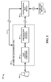
- FIG. 1 is a block diagram of an automation configuration tool in
- a component is intended to refer to a computer-related entity, either hardware, a combination of hardware and software, software, or software in execution.
- a component may be, but is not limited to being, a process running on a processor, a processor, an object, an executable, a thread of execution, a program, and / or a computer.
- an application running on a server and the server can be a computer component.
- One or more components may reside within a process and / or thread of execution and a component may be localized on one computer and / or distributed between two or more computers.
- the subject matter may be implemented as a method, apparatus, or article of manufacture using standard programming and / or engineering techniques to produce software, firmware, hardware, or any combination thereof.
- article of manufacture (or alternatively, “computer program product”) as used herein is intended to encompass a computer program accessible from any computer-readable device, carrier, or media.
- an automation configuration tool can utilize, for example, standard personal computer (PC) systems to perform configuration of distributed automation systems without requiring additional software to be installed.
- Parameterization of the configuration device itself can occur automatically by retrieving data from an explorable automation network, saving substantial effort and time for an automation system integrator.
- the parametric data can be stored locally with an automation device, with a configuration gateway/server, and/or in a remote location accessible by the automation configuration tool.
- the automation configuration tool can also remotely configure automation devices via an automation configuration gateway.
- FIG. 1 illustrates an instance 100 of an automation configuration tool 102 that interfaces with a user 104 and an automation device 106 via an automation configuration gateway 108.
- the automation configuration gateway 108 serves the automation configuration tool 102 and provides a communication link between the automation configuration tool 102 and the automation device 106.
- the automation configuration tool 102 is comprised of an automation configuration applet that is a self-contained software application that can run within a Web browser. Thus, the automation configuration tool 102 does not require an automation system integrator to load additional software on a computing device in order to utilize the automation configuration tool 102.
- the configuration applet can employ, for example, Sun Microsystems JavaTM code to perform configuration tasks within the Web browser.
- the automation configuration tool 102 can reside remotely to the automation configuration gateway 108 and/or the automation device 106.
- the automation configuration tool 102 can configure and/or monitor multiple devices via the automation configuration gateway 108.
- Communications between the automation configuration tool 102, the automation configuration gateway 108, and the automation device 106 can be a local area network (LAN) and/or a wide area network (WAN), the Internet and/or an intranet, and/or other wired and/or wireless communications and the like.
- FIG. 2 Another instance 200 of an automation configuration tool 202 is shown in FIG. 2.
- the automation configuration tool 202 interfaces with a user 204 and automation devices 206 via an automation configuration web server 208.
- the automation configuration tool 202 utilizes a user interface component 210 and a configuration gateway interface 212.
- the configuration gateway interface 212 establishes communications with a configuration gateway hosted by the configuration web server 208 to allow communications between the user interface component 210 and the automation devices 206.
- the user interface component 210 displays data, controls, configuration parameters, and/or other parameters to the user 204. The displayed information can be influenced/guided by the automation devices 206 themselves.
- the automation configuration tool 202 is served up by the configuration web server 208 (denoted by line 214).
- the initiation of the automation configuration tool 202 is typically accomplished via a web browser with web page information served by the configuration web server 208. This allows the user 204 to select the automation configuration tool 202 for use via a web browser.
- the configuration web server 208 typically provides a separate instantiation of a configuration gateway for each instantiation of the automation configuration tool 202. This allows multiple automation configuration tools to operate independently of each other to interact with automation devices 206. Communications between the automation configuration tool 202, the automation configuration gateway 208, and the automation device 206 can be a local area network (LAN) and/or a wide area network (WAN), the Internet and/or an intranet, and/or other wired and/or wireless communications and the like.
- LAN local area network
- WAN wide area network
- the Internet and/or an intranet
- the above tools can also be utilized in standard-based systems such as, for example, IEC 61499 compliant automation systems.
- the automation configuration tool can display various types of parameters and offer possibilities to change them appropriately for each system. These parameters can be displayed in a general way, i.e ., by the use of editable text fields, which display the value.
- the device itself can choose an appropriate appearance from a library of possible human-machine interface (HMI) IEC 61499 function blocks, which can be provided by, for example, a function block runtime environment (FBRT) (developed by James H. Christensen) for display purposes.
- HMI human-machine interface
- FBRT function block runtime environment
- a configuration marker function block can be utilized. This function block can also contain information about a preferred appearance of a parameter.
- the configuration marker is described in further detail infra.
- An example structure 300 is illustrated in FIG. 3.
- An automation configuration tool in this example, is a configuration applet 302 that runs on a PC system 304.
- the configuration applet 302 is based on a Java coded applet that is included in an HTML web-page served by an HTTP-server 306 that is part of a configuration web server 308.
- the configuration web server 308 is also used to execute an IEC 61499 remote device 310, which can be accessed by the configuration applet 302 via, for example, a TCP/IP connection.
- Management commands sent from the configuration applet 302 to the remote device 310 cause it to instantiate an automation configuration gateway 312.
- the configuration applet 302 disconnects from the remote device 310 to build a new connection to the freshly created automation configuration gateway 312.
- This gateway 312 provides the interface to forward, for example, extensible markup language (XML) commands from the configuration applet 302 to the device 310, which is configured, for example, via TCP/IP connections. It also includes the network exploration application to inform the configuration applet 302 about present devices 314 on an automation network 316.
- the configuration applet 302 and/or the automation configuration gateway 312 can be constructed according to IEC 61499 function block structures. Multiple configuration access can be established because each configuration applet can create its own automation configuration gateway instance to access an automation system. Thus, instances disclosed herein provide platform-independent configuration tools that are available without the need of additional program installations on hosted computing devices.
- a configuration marker can be utilized.
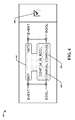
- a configuration marker function block can be used to mark data and event inputs of selected function blocks and, by a differentiated type structure of the marker function blocks, to define the appearance of the configurable data input. For example, function blocks which are designated as a special type are considered as configurable. The type name of these function blocks can begin with, for example, a "CONF_M " string and their structure as illustration 400 depicts in FIG. 4.
- FIG. 4 also illustrates a graphical representation 408 of the configuration marker for a Boolean parameter.
- the graphical representation 408 can also be constructed of other graphical user interface (GUI) elements such as knob, sliders, and/or pointers and the like, depending on the type of data.
- GUI graphical user interface
- a service interface function block 402 performs a mapping of the data input value 404 (CONNIVAL) to the data output 406 (CONNOVAL), which is connected to a specific data input, which is configurable.
- CONNIVAL data input value
- CONNOVAL data output 406
- the remaining string of the configuration marker's type name can be utilized to define the appearance of a configuration parameter.
- this string can refer to an HMI function block of the FBRT library, which selects it for display.
- a function block supporting the configuration marker can process a changed value in several ways.
- One way is to connect the data output CONNOVAL of the configuration marker function block to this function block as shown in the left part 502 (without autonomous event creation on parameter change) of the illustration 500 of FIG. 5. The value is then processed every time the algorithm of the function block needs it.
- Another way is to connect the data and the event output of the configuration marker function block to this function block according to the right part 504 (with autonomous event creation on parameter change) of FIG. 5.
- Each time a user downloads values from a configuration applet to a resource the configuration marker function blocks are restarted. The resulting event can be used to notify a connected function block that a possible change of a parameter value could have occurred.
- a configuration applet 602 shown in an illustration 600 of FIG. 6 can access automation device 604 by navigating through gateway 1 606, gateway 2 608, and gateway 3 610 for example. This substantially increases the flexibility of the configuration applet 602 and increases its configuration capabilities by extending its reach to multiple automation networks. Selection of various gateways and/or automation devices via a configuration tool is described in further detail infra.
- the configuration tool represents an HMI which allows access to automation networks by the use of the previously described gateways.
- instances of configuration tools disclosed herein can include several functions such as, for example, configuration gateway initiation and/or connection, listing of automation network devices, and/or detailed device exploration and parameterization and the like.
- a configuration applet can be based on a modular structure to enable easy implementation of these functions into other applications and/or to extend the provided functionality with new ones.
- a configuration gateway sends a list of device identifiers from detected automation devices on request by a configuration applet.
- the list could include IDs of standard-compliant devices (e.g., IEC 61499 compliant devices) and non-compliant ones.
- the non-compliant devices typically cannot be configured and, therefore, often need to be specially marked.
- the displayed list can consist of standard conforming and non-conforming devices and can even include additional information about them. For example, a name of a device, if available, can give information about the type of tasks it fulfills.
- the list can also be further enhanced by using, for example, a prefixed plus character ("+") to identify devices which are configuration gateways.
- a user can also choose to list devices which are in an adjacent network and the like.
- the resulting display can be organized in a "tree-structure," as shown in an illustration 700 in FIG. 7 (a parameter display of a device and its resources).
- a prefixed "(nc)" string can indicate that the device is not conforming to a standard and is therefore not explorable (see FIG. 7).
- An automation device can be selected from a list and explored in more detail, which can result in a display of some or all configurable parameters it provides.
- These parameters can be recognized, for example, by means of a configuration marker function block, which stores the name and the type of the configurable parameter. Its appearance can be defined by the type of the configuration marker, which the developer of the device can define, because each configuration marker type can refer to an HMI function block in a class library of an FBRT.
- Parameters can be listed in order of the resources they are included in as shown in an illustration 800 in FIG. 8. For example, parameters responsible for direct automation device configuration can be listed first, followed by the parameters embedded into the resources.
- HMI function blocks that are responsible for an appropriate display of configuration parameters can also be utilized to change a value according to the user's needs.
- the download of the new parameter values to an automation device can be accomplished for a whole resource by, for example, pressing an appropriate "download" button 802 (see FIG. 8) and/or some other similar control and the like.
- the parameter values of this resource are queried again and displayed. Errors that occurred while attempting to display or download parameters and values can be displayed directly next to a parameter.
- HMI function blocks like check-boxes, slide-bars, choice and text fields, and/or buttons and the like can be utilized for displaying parameters and/or configuration controls. It is possible to develop new types of HMI input components and add them to an HMI class library.
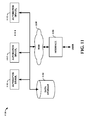
- FIG. 9 is an illustration of an example HMI 900 for a configuration tool disclosed herein.
- Various function blocks 902-906 are utilized to display communication parameters, device lists, and display parameters.
- a communication control function block 902 can be utilized to construct and release connections to a configuration gateway and/or provide an interface to the configuration gateway for other resources. It connects to a remote device on a configuration web server from which a configuration applet is served and instantiates a configuration gateway on this device. When this is achieved, it can disconnect from the remote device and connect to the generated configuration gateway.
- a device list function block 904 can be utilized to display detected automation devices of a configurable automation network and/or to permit a user to interact with them.
- a device display function block 906 can be utilized to construct detailed configuration views of selected automation devices, to display configurable parameters, and/or to manipulate the configurable parameters and the like.
- FIG. 10 illustrates a typical automation system 1000 for reference.
- the automation system 1000 is comprised of one or more automation device(s) 1002 (AUTOMATION DEVICE 1 through AUTOMATION DEVICE N , where N is an integer from one to infinity), data storage 1004 and interface 1006.
- Automation device(s) 1002 can include any one of a plurality of industrial, commercial and/or entertainment processes and machines such as programmable logic controllers (PLCs), pumps providing fluid transport and other processes, fans, conveyor systems, compressors, gear boxes, motion control and detection devices, sensors, screw pumps, and mixers, as well as hydraulic and pneumatic machines driven by motors.
- PLCs programmable logic controllers
- Such motors can be combined with other components, such as valves, pumps, furnaces, heaters, chillers, conveyor rollers, fans, compressors, gearboxes, and the like, as well as with appropriate motor drives to form industrial machines and actuators.
- an electric motor could be combined with a motor drive providing variable electrical power to the motor, as well as with a pump, whereby the motor rotates the pump shaft to create a controllable pumping system.
- Data storage 1004 provides a storage location for housing data relating to automation device(s) 1002 including but not limited to device description, location, and mechanical condition, energy or fuel consumption, completed cycles, horsepower, average RPM, efficiency rating, as well as data from sensors regarding device health and / or performance.
- the data storage 1004 can be integrated or federated and linked by a communication system.
- Interface 1006 is operable to connect users with a network of automation devices 1002 and / or data storage 1004 via a wire (e.g ., twisted pair, coaxial cable, optical fiber, Ethernet, USB (Universal Serial Bus), FireWire) or wirelessly ( e.g. , using IEEE 802.11a and / or IEEE 802.11b standards, Bluetooth technology, satellite).
- Interface 1006 facilitates monitoring, extracting, transmitting, and otherwise interacting with automation device(s) 1002 and associated data.
- a user such as, for example, a device operator can connect to data storage 1004 and automation devices 1002 over a local area network (LAN) utilizing a variety of LAN technologies, including Fiber Distributed Data Interface (FDDI), Copper Distributed Data Interface (CDDI), Ethernet/IEEE 802.3, Token Ring/IEEE 802.5, physical connection topologies such as bus, tree, ring, and star, and the like.
- FDDI Fiber Distributed Data Interface
- CDDI Copper Distributed Data Interface
- Ethernet/IEEE 802.3 Ethernet/IEEE 802.3
- Token Ring/IEEE 802.5 physical connection topologies such as bus, tree, ring, and star, and the like.
- communications between networked devices such as automation devices 1002, data storage 1004, and interface 1006 need not be limited to those devices connected locally to a network. Local networked devices can also communicate to and from remote devices.
- FIG. 11 is substantially the same as system 1000 except that a user employs interface 1106 to interact with automation devices 1102 and data storage 1104 remotely over a wide area network (WAN) 1108.
- WANs 1108 are communication networks that span a large geographic area (e.g., nationwide, worldwide) and generally consist of the several interconnected local area networks (LANs) and metropolitan area networks (MANs). The largest WAN 1108 in existence today is the Internet.
- WAN technologies include, but are not limited to, point-to-point links, circuit switching networks like Integrated Services Digital Networks (ISDN) and variations thereon, packet switching networks, T1 networks, and Digital Subscriber Lines (DSL).
- ISDN Integrated Services Digital Networks
- DSL Digital Subscriber Lines
- the embodiments may be described in the general context of computer-executable instructions, such as program modules, executed by one or more components.
- program modules include routines, programs, objects, data structures, etc., that perform particular tasks or implement particular abstract data types.
- functionality of the program modules may be combined or distributed as desired in various instances of the embodiments.
- FIG. 12 a flow diagram of a method 1200 of configuring automation control systems in accordance with an aspect of an embodiment is shown.
- the method 1200 starts 1202 by employing a self-contained software application that operates within a web browser to interact with a configuration gateway and provide a human-machine interface for automation device configuration 1204.
- the self-contained software application is served up by a configuration web server along with an HTML web page.
- the configuration web server can also provide the configuration gateway that the self-contained software application interacts with.
- the self-contained software application can included, but is not limited to, a configuration applet based on Sun Microsystems JavaTM code and the like.
- an automation system engineer is not required to load additional software on a computing device just to configure automation devices.
- the engineer can configure automation devices in a remote fashion by initiating a web page served by the configuration web server and initiating the self-contained software application.
- Function specific device parameters for the automation devices in an automation network are then configured and/or monitored via the self-contained software application 1206, ending the flow 1208.
- the parameters are typically obtained from remote locations via one or more configuration gateways. The flexibility of utilizing multiple gateways allows the self-contained software application to communication with multiple automation networks and their devices.
- FIG. 13 another flow diagram of a method 1300 of configuring automation control systems in accordance with an aspect of an embodiment is depicted.
- the method 1300 starts 1302 by employing a self-contained software application functioning within a web browser and interacting with a configuration gateway 1304.
- the self-contained software application can included, but is not limited to, a configuration applet based on Sun Microsystems JavaTM code and the like.
- Device-assisted formatted configuration information is then displayed to a user based on, at least in part, data obtained from at least one automation device via the configuration gateway 1306, ending the flow 1308.
- the self-contained software application can display configurable parameters utilizing provided information.
- the provided information can originate directly from an automation device and/or from another source such as, for example, a configuration web server and the like, including from the configuration gateway.
- the storing of the configuration data can reside in other locations accessible by the self-contained software application as well.
- Some instances, such as IEC 61499 compliant devices can employ a configuration marker to facilitate in determining how parameters should be displayed and what aspects can be configured and the like.
- FIG. 14 and the following discussion is intended to provide a brief, general description of a suitable computing environment 1400 in which the various aspects of the embodiments can be implemented. While the embodiments have been described above in the general context of computer-executable instructions of a computer program that runs on a local computer and / or remote computer, those skilled in the art will recognize that the embodiments can also be implemented in combination with other program modules. Generally, program modules include routines, programs, components, data structures, etc., that perform particular tasks and / or implement particular abstract data types.
- inventive methods can be practiced with other computer system configurations, including single-processor or multi-processor computer systems, minicomputers, mainframe computers, as well as personal computers, handheld computing devices, microprocessor-based and / or programmable consumer electronics, and the like, each of which can operatively communicate with one or more associated devices.
- the illustrated aspects of the embodiments can also be practiced in distributed computing environments where certain tasks are performed by remote processing devices that are linked through a communications network. However, some, if not all, aspects of the embodiments can be practiced on stand-alone computers.
- program modules can be located in local and / or remote memory storage devices.
- a component is intended to refer to a computer-related entity, either hardware, a combination of hardware and software, software, or software in execution.
- a component can be, but is not limited to, a process running on a processor, a processor, an object, an executable, a thread of execution, a program, and a computer.
- an application running on a server and / or the server can be a component.
- a component can include one or more subcomponents.
- an exemplary environment 1410 for implementing various aspects of the invention includes a computer 1412.
- the computer 1412 includes a processing unit 1414, a system memory 1416, and a system bus 1418.
- the system bus 1418 couples system components including, but not limited to, the system memory 1416, to the processing unit 1414.
- the processing unit 1414 can be any of various available processors. Dual microprocessors and other multiprocessor architectures also can be employed as the processing unit 1414.
- the system bus 1418 can be any of several types of bus structure(s) including the memory bus or memory controller, a peripheral bus or external bus, and/or a local bus using any variety of available bus architectures including, but not limited to, 16-bit bus, Industrial Standard Architecture (ISA), Micro-Channel Architecture (MSA), Extended ISA (EISA), Intelligent Drive Electronics (IDE), VESA Local Bus (VLB), Peripheral Component Interconnect (PCI), Universal Serial Bus (USB), Advanced Graphics Port (AGP), Personal Computer Memory Card International Association bus (PCMCIA), and Small Computer Systems Interface (SCSI).
- ISA Industrial Standard Architecture
- MSA Micro-Channel Architecture
- EISA Extended ISA
- IDE Intelligent Drive Electronics
- VLB VESA Local Bus
- PCI Peripheral Component Interconnect
- USB Universal Serial Bus
- AGP Advanced Graphics Port
- PCMCIA Personal Computer Memory Card International Association bus
- SCSI Small Computer Systems Interface
- the system memory 1416 includes volatile memory 1420 and nonvolatile memory 1422.
- the basic input/output system (BIOS) containing the basic routines to transfer information between elements within the computer 1412, such as during start-up, is stored in nonvolatile memory 1422.
- nonvolatile memory 1422 can include read only memory (ROM), programmable ROM (PROM), electrically programmable ROM (EPROM), electrically erasable ROM (EEPROM), or flash memory.
- Volatile memory 1420 includes random access memory (RAM), which acts as external cache memory.
- RAM is available in many forms such as synchronous RAM (SRAM), dynamic RAM (DRAM), synchronous DRAM (SDRAM), double data rate SDRAM (DDR SDRAM), enhanced SDRAM (ESDRAM), Synchlink DRAM (SLDRAM), and direct Rambus RAM (DRRAM).
- SRAM synchronous RAM
- DRAM dynamic RAM
- SDRAM synchronous DRAM
- DDR SDRAM double data rate SDRAM
- ESDRAM enhanced SDRAM
- SLDRAM Synchlink DRAM
- DRRAM direct Rambus RAM
- Disk storage 1424 includes, but is not limited to, devices like a magnetic disk drive, floppy disk drive, tape drive, Jaz drive, Zip drive, LS-100 drive, flash memory card, or memory stick.
- disk storage 1424 can include storage media separately or in combination with other storage media including, but not limited to, an optical disk drive such as a compact disk ROM device (CD-ROM), CD recordable drive (CD-R Drive), CD rewritable drive (CD-RW Drive) or a digital versatile disk ROM drive (DVD-ROM).
- an optical disk drive such as a compact disk ROM device (CD-ROM), CD recordable drive (CD-R Drive), CD rewritable drive (CD-RW Drive) or a digital versatile disk ROM drive (DVD-ROM).
- a removable or non-removable interface is typically used such as interface 1426.
- Fig 14 describes software that acts as an intermediary between users and the basic computer resources described in suitable operating environment 1410.
- Such software includes an operating system 1428.
- Operating system 1428 which can be stored on disk storage 1424, acts to control and allocate resources of the computer system 1412.
- System applications 1430 take advantage of the management of resources by operating system 1428 through program modules 1432 and program data 1434 stored either in system memory 1416 or on disk storage 1424. It is to be appreciated that the present invention can be implemented with various operating systems or combinations of operating systems.
- Input devices 1436 include, but are not limited to, a pointing device such as a mouse, trackball, stylus, touch pad, keyboard, microphone, joystick, game pad, satellite dish, scanner, TV tuner card, digital camera, digital video camera, web camera, and the like. These and other input devices connect to the processing unit 1414 through the system bus 1418 via interface port(s) 1438.
- Interface port(s) 1438 include, for example, a serial port, a parallel port, a game port, and a universal serial bus (USB).
- Output device(s) 1440 use some of the same type of ports as input device(s) 1436.
- a USB port may be used to provide input to computer 1412 and to output information from computer 1412 to an output device 1440.
- Output adapter 1442 is provided to illustrate that there are some output devices 1440 like monitors, speakers, and printers, among other output devices 1440 that require special adapters.
- the output adapters 1442 include, by way of illustration and not limitation, video and sound cards that provide a means of connection between the output device 1440 and the system bus 1418. It should be noted that other devices and/or systems of devices provide both input and output capabilities such as remote computer(s) 1444.
- Computer 1412 can operate in a networked environment using logical connections to one or more remote computers, such as remote computer(s) 1444.
- the remote computer(s) 1444 can be a personal computer, a server, a router, a network PC, a workstation, a microprocessor based appliance, a peer device or other common network node and the like, and typically includes many or all of the elements described relative to computer 1412. For purposes of brevity, only a memory storage device 1446 is illustrated with remote computer(s) 1444.
- Remote computer(s) 1444 is logically connected to computer 1412 through a network interface 1448 and then physically connected via communication connection 1450.
- Network interface 1448 encompasses communication networks such as local-area networks (LAN) and wide-area networks (WAN).
- LAN technologies include Fiber Distributed Data Interface (FDDI), Copper Distributed Data Interface (CDDI), Ethernet/IEEE 802.3, Token Ring/IEEE 802.5 and the like.
- WAN technologies include, but are not limited to, point-to-point links, circuit switching networks like Integrated Services Digital Networks (ISDN) and variations thereon, packet switching networks, and Digital Subscriber Lines (DSL).
- ISDN Integrated Services Digital Networks
- DSL Digital Subscriber Lines
- Communication connection(s) 1450 refers to the hardware/software employed to connect the network interface 1448 to the bus 1418. While communication connection 1450 is shown for illustrative clarity inside computer 1412, it can also be external to computer 1412.
- the hardware/software necessary for connection to the network interface 1448 includes, for exemplary purposes only, internal and external technologies such as, modems including regular telephone grade modems, cable modems and DSL modems, ISDN adapters, and Ethernet cards.
- FIG. 15 is another block diagram of a sample computing environment 1500 with which embodiments can interact.
- the system 1500 further illustrates a system that includes one or more client(s) 1502.
- the client(s) 1502 can be hardware and / or software ( e.g ., threads, processes, computing devices).
- the system 1500 also includes one or more server(s) 1504.
- the server(s) 1504 can also be hardware and / or software ( e.g ., threads, processes, computing devices).
- One possible communication between a client 1502 and a server 1504 can be in the form of a data packet adapted to be transmitted between two or more computer processes.
- the system 1500 includes a communication framework 1508 that can be employed to facilitate communications between the client(s) 1502 and the server(s) 1504.
- the client(s) 1502 are connected to one or more client data store(s) 1510 that can be employed to store information local to the client(s) 1502.
- the server(s) 1504 are connected to one or more server data store(s) 1506 that can be employed to store information local to the server(s) 1504.
- a data packet transmitted between two or more computer components that facilitates configuration of automation systems is comprised of, at least in part, information routed through a configuration gateway and relayed between a configuration applet running on a web browser and/or an automation device connected to an automation network.
- systems and / or methods of the embodiments can be utilized in automation configuration tool facilitating computer components and non-computer related components alike. Further, those skilled in the art will recognize that the systems and / or methods of the embodiments are employable in a vast array of electronic related technologies, including, but not limited to, computers, servers and / or handheld electronic devices, and the like.
- a configuration tool provides a user interface that interacts with a gateway to remotely configure and/or monitor automation devices in an automation network.
- the configuration tool employs a self-contained software application (e.g ., applet) that can be utilized for presentation and configuration interactions within a common web browser.
- the configuration tool can be based on open standards and implemented with small devices and/or with heterogeneous automation networks.
- the configuration tool can provide a list of automation devices to a system engineer via a workstation and standard software (e . g ., a PC with a browser).
- the configuration tool interacts with automation devices to obtain their configurable parameters and/or send configuration commands.
- the configuration tool and the automation network devices are based on Java and IEC 61499, respectively.
Applications Claiming Priority (1)
| Application Number | Priority Date | Filing Date | Title |
|---|---|---|---|
| US11/536,898 US8683017B2 (en) | 2006-09-29 | 2006-09-29 | Web-based configuration of distributed automation systems |
Publications (2)
| Publication Number | Publication Date |
|---|---|
| EP1906592A1 true EP1906592A1 (fr) | 2008-04-02 |
| EP1906592B1 EP1906592B1 (fr) | 2017-12-27 |
Family
ID=38941854
Family Applications (1)
| Application Number | Title | Priority Date | Filing Date |
|---|---|---|---|
| EP07115135.1A Active EP1906592B1 (fr) | 2006-09-29 | 2007-08-28 | Configuration basée sur le web de systèmes d'automatisation distribués |
Country Status (3)
| Country | Link |
|---|---|
| US (1) | US8683017B2 (fr) |
| EP (1) | EP1906592B1 (fr) |
| CN (1) | CN101154106B (fr) |
Cited By (5)
| Publication number | Priority date | Publication date | Assignee | Title |
|---|---|---|---|---|
| WO2009104036A1 (fr) * | 2008-02-19 | 2009-08-27 | Abb Research Limited | Architecture de client léger pour un poste de travail d'ingénierie dans un système d'automatisation |
| CN101593112B (zh) * | 2009-06-23 | 2012-05-23 | 中兴通讯股份有限公司 | 一种自适应显示终端产品配套软件页面的方法及系统 |
| CN103414570A (zh) * | 2013-09-05 | 2013-11-27 | 厦门鼎运软件有限公司 | 一种远程密码管控的方法 |
| EP3739849A1 (fr) * | 2019-05-17 | 2020-11-18 | Valmet Automation Oy | Accès à distance de système d'automatisation |
| WO2024013101A1 (fr) | 2022-07-11 | 2024-01-18 | Phoenix Contact Gmbh & Co.Kg | Procédé et dispositif de fonctionnement pour échanger des données |
Families Citing this family (16)
| Publication number | Priority date | Publication date | Assignee | Title |
|---|---|---|---|---|
| US8990768B2 (en) * | 2008-09-30 | 2015-03-24 | Rockwell Automation Technologies, Inc. | Software object property return method and system |
| US8155761B2 (en) * | 2009-07-23 | 2012-04-10 | Fisher-Rosemount Systems, Inc. | Process control system with integrated external data sources |
| WO2013137884A1 (fr) * | 2012-03-15 | 2013-09-19 | Schneider Electric Industries Sas | Gestion des adresses de dispositifs dans un système de régulation d'automation |
| CN103634138B (zh) * | 2012-08-27 | 2016-12-28 | 阿里巴巴集团控股有限公司 | 分布式调度的远程管理与运维方法及其系统 |
| US9558286B2 (en) | 2012-12-06 | 2017-01-31 | At&T Intellectual Property I, L.P. | Methods, systems, and products for generating mashups |
| DE102013107905A1 (de) * | 2013-07-24 | 2015-01-29 | Endress + Hauser Process Solutions Ag | Feldbuszugriffseinheit und Verfahren zum Betreiben derselben |
| US10671030B2 (en) * | 2013-12-06 | 2020-06-02 | Siemens Schweiz Ag | Web-based interaction with building automation |
| US10085328B2 (en) | 2014-08-11 | 2018-09-25 | RAB Lighting Inc. | Wireless lighting control systems and methods |
| US10039174B2 (en) | 2014-08-11 | 2018-07-31 | RAB Lighting Inc. | Systems and methods for acknowledging broadcast messages in a wireless lighting control network |
| US10531545B2 (en) | 2014-08-11 | 2020-01-07 | RAB Lighting Inc. | Commissioning a configurable user control device for a lighting control system |
| US9883567B2 (en) | 2014-08-11 | 2018-01-30 | RAB Lighting Inc. | Device indication and commissioning for a lighting control system |
| DE102014119515A1 (de) | 2014-12-23 | 2016-06-23 | Endress + Hauser Wetzer Gmbh + Co Kg | Verfahren zum Betreiben eines Feldgerätes sowie Anordnung umfassend ein Feldgerät |
| CN107947970B (zh) * | 2017-11-16 | 2018-09-11 | 国网山东省电力公司临沂供电公司 | 一种利用图形化管理特定类型网络配置命令的方法 |
| WO2020193280A1 (fr) * | 2019-03-28 | 2020-10-01 | Inventio Ag | Procédé et système de mise en service d'une passerelle de communication |
| CN110795024B (zh) * | 2019-10-12 | 2021-03-26 | 北京四方继保自动化股份有限公司 | 一种基于xml的保护设备通用人机交互系统及方法 |
| DE102022117153A1 (de) | 2022-07-11 | 2024-01-11 | Phoenix Contact Gmbh & Co. Kg | Verfahren und Bediengerät zum Austauschen von Daten |
Citations (2)
| Publication number | Priority date | Publication date | Assignee | Title |
|---|---|---|---|---|
| WO1998053581A1 (fr) | 1997-05-19 | 1998-11-26 | Coactive Networks, Inc. | Systeme serveur et procede permettant de connecter des reseaux de commande et des dispositifs a entree/sortie directes par l'intermediaire du world wide web |
| WO2003079126A1 (fr) | 2002-03-14 | 2003-09-25 | Schneider Automation Inc. | Systeme et procede donnant acces a des dispositifs dans le reseau d'automatisation d'une usine |
Family Cites Families (24)
| Publication number | Priority date | Publication date | Assignee | Title |
|---|---|---|---|---|
| US7035898B1 (en) * | 1997-09-10 | 2006-04-25 | Schneider Automation Inc. | System for programming a factory automation device using a web browser |
| US6282454B1 (en) * | 1997-09-10 | 2001-08-28 | Schneider Automation Inc. | Web interface to a programmable controller |
| US6201996B1 (en) * | 1998-05-29 | 2001-03-13 | Control Technology Corporationa | Object-oriented programmable industrial controller with distributed interface architecture |
| JP2000047857A (ja) * | 1998-07-27 | 2000-02-18 | Yamatake Corp | イベント駆動型ファンクションブロックのプログラミング方法とプログラム記録媒体 |
| US7017116B2 (en) * | 1999-01-06 | 2006-03-21 | Iconics, Inc. | Graphical human-machine interface on a portable device |
| US6718533B1 (en) * | 1999-02-26 | 2004-04-06 | Real-Time Innovations, Inc. | Method for building a real-time control system with mode and logical rate |
| US6477435B1 (en) * | 1999-09-24 | 2002-11-05 | Rockwell Software Inc. | Automated programming system for industrial control using area-model |
| JP2001282655A (ja) * | 2000-03-28 | 2001-10-12 | Canon Inc | ネットワークデバイス管理方法、装置、および記憶媒体 |
| AUPQ808700A0 (en) | 2000-06-09 | 2000-07-06 | Honeywell Limited | Human-machine interface |
| US7290030B2 (en) * | 2001-07-13 | 2007-10-30 | Rockwell Automation Technologies, Inc. | Internet object based interface for industrial controller |
| US20030105535A1 (en) * | 2001-11-05 | 2003-06-05 | Roman Rammler | Unit controller with integral full-featured human-machine interface |
| US7054922B2 (en) * | 2001-11-14 | 2006-05-30 | Invensys Systems, Inc. | Remote fieldbus messaging via Internet applet/servlet pairs |
| US7165226B2 (en) * | 2002-08-23 | 2007-01-16 | Siemens Aktiengesellschaft | Multiple coupled browsers for an industrial workbench |
| JP3930404B2 (ja) | 2002-09-09 | 2007-06-13 | 三菱重工業株式会社 | 自律分散型システム及びその通信方法 |
| US20040230328A1 (en) | 2003-03-21 | 2004-11-18 | Steve Armstrong | Remote data visualization within an asset data system for a process plant |
| US20040210664A1 (en) * | 2003-04-17 | 2004-10-21 | Schneider Automation Inc. | System and method for transmitting data |
| US20050043620A1 (en) * | 2003-08-20 | 2005-02-24 | Siemens Medical Solutions Usa, Inc. | Diagnostic medical ultrasound system communication network architecture and method |
| US7324856B1 (en) * | 2003-09-25 | 2008-01-29 | Rockwell Automation Technologies, Inc. | Autogeneration of code via human-machine interfaces (HMI) and self-building HMI |
| US20050155043A1 (en) * | 2004-01-08 | 2005-07-14 | Schulz Kurt S. | Human-machine interface system and method for remotely monitoring and controlling a machine |
| JP2007536634A (ja) * | 2004-05-04 | 2007-12-13 | フィッシャー−ローズマウント・システムズ・インコーポレーテッド | プロセス制御システムのためのサービス指向型アーキテクチャ |
| EP1674954A1 (fr) * | 2004-12-21 | 2006-06-28 | Siemens Aktiengesellschaft | Sytème et procédé de réutilisation des données de conception |
| US7418305B2 (en) * | 2005-02-09 | 2008-08-26 | Siemens Corporate Research, Inc. | Method of generating a component of a component-based automation system |
| US7706895B2 (en) * | 2005-02-25 | 2010-04-27 | Rockwell Automation Technologies, Inc. | Reliable messaging instruction |
| US20080080543A1 (en) * | 2006-09-28 | 2008-04-03 | Rockwell Automation Technologies, Inc. | Network switch with controller i/o capability |
-
2006
- 2006-09-29 US US11/536,898 patent/US8683017B2/en active Active
-
2007
- 2007-08-28 EP EP07115135.1A patent/EP1906592B1/fr active Active
- 2007-09-28 CN CN2007101623387A patent/CN101154106B/zh active Active
Patent Citations (2)
| Publication number | Priority date | Publication date | Assignee | Title |
|---|---|---|---|---|
| WO1998053581A1 (fr) | 1997-05-19 | 1998-11-26 | Coactive Networks, Inc. | Systeme serveur et procede permettant de connecter des reseaux de commande et des dispositifs a entree/sortie directes par l'intermediaire du world wide web |
| WO2003079126A1 (fr) | 2002-03-14 | 2003-09-25 | Schneider Automation Inc. | Systeme et procede donnant acces a des dispositifs dans le reseau d'automatisation d'une usine |
Non-Patent Citations (2)
| Title |
|---|
| LUMPP T ET AL: "Virtual Java devices. Integration of fieldbus based systems in the Internet", INDUSTRIAL ELECTRONICS SOCIETY, 1998. IECON '98. PROCEEDINGS OF THE 24TH ANNUAL CONFERENCE OF THE IEEE AACHEN, GERMANY 31 AUG.-4 SEPT. 1998, NEW YORK, NY, USA,IEEE, US, vol. 1, 31 August 1998 (1998-08-31), pages 176 - 181, XP010308211, ISBN: 0-7803-4503-7 * |
| LUMPP, T ET AL.: "Virtual Java devices. Integration of fieldbus-based systems in the Internet", INDUSTRIAL ELECTRONICS SOCIETY, 1998. IECON '98, PROCEEDINGS OF THE 24TH ANNUAL CONFERENCE OF THE IEEE, vol. 1, 31 August 1998 (1998-08-31), pages 176 - 181, XP010308211, DOI: doi:10.1109/IECON.1998.723972 |
Cited By (6)
| Publication number | Priority date | Publication date | Assignee | Title |
|---|---|---|---|---|
| WO2009104036A1 (fr) * | 2008-02-19 | 2009-08-27 | Abb Research Limited | Architecture de client léger pour un poste de travail d'ingénierie dans un système d'automatisation |
| CN101593112B (zh) * | 2009-06-23 | 2012-05-23 | 中兴通讯股份有限公司 | 一种自适应显示终端产品配套软件页面的方法及系统 |
| CN103414570A (zh) * | 2013-09-05 | 2013-11-27 | 厦门鼎运软件有限公司 | 一种远程密码管控的方法 |
| EP3739849A1 (fr) * | 2019-05-17 | 2020-11-18 | Valmet Automation Oy | Accès à distance de système d'automatisation |
| US11435724B2 (en) | 2019-05-17 | 2022-09-06 | Valmet Automation Oy | Automation system remote access |
| WO2024013101A1 (fr) | 2022-07-11 | 2024-01-18 | Phoenix Contact Gmbh & Co.Kg | Procédé et dispositif de fonctionnement pour échanger des données |
Also Published As
| Publication number | Publication date |
|---|---|
| CN101154106B (zh) | 2012-11-28 |
| EP1906592B1 (fr) | 2017-12-27 |
| US20080082637A1 (en) | 2008-04-03 |
| US8683017B2 (en) | 2014-03-25 |
| CN101154106A (zh) | 2008-04-02 |
Similar Documents
| Publication | Publication Date | Title |
|---|---|---|
| US8683017B2 (en) | Web-based configuration of distributed automation systems | |
| US8028045B2 (en) | Web-based configuration server for automation systems | |
| EP1531373B1 (fr) | Procédé et méthode d'automatisation industrielle avec une interface dynamique de navigation | |
| EP1873634A2 (fr) | Cadre IHM pour plates-formes d'ingénierie de systèmes d'automatisation extensibles | |
| US11467720B2 (en) | Systems and methods for automatically populating a display area with historized process parameters | |
| EP3165977B1 (fr) | Téléchargement et enregistrement automatiques de fichiers de description de dispositifs | |
| EP1873633A2 (fr) | Visualisation IHM d'automatisation utilisant des blocs fonctionnels IUG | |
| EP2889709A2 (fr) | Dispositif d'automatisation industrielle avec éditeur et visualisation mobile d'objet graphique | |
| EP1691245A1 (fr) | Automatisation sur base de composants | |
| US7650198B2 (en) | Automation system unified data access for disparate data sources | |
| US20060095855A1 (en) | HMI reconfiguration method and system | |
| EP2357541B1 (fr) | Bloc de fonction macro pour logique intégrée au niveau d'un dispositif d'encapsulation | |
| CN205959050U (zh) | 一体机控制装置 | |
| US20230393547A1 (en) | Human-machine execution system applied to manufacturing | |
| US20170168474A1 (en) | Robot control device and communication system having communication function for communicating with programmable logic controller | |
| US10802458B2 (en) | System for building an industrial control program from device type classes having device specific instructions | |
| Kafader | Motion Control for Newbies. | |
| Dehner | Controller embeds programming efficiency: Selecting the right controller and accompanying programming software adds efficiency to the controller programming process | |
| Burns | Mechatronic motion control sets Industrie 4.0 in motion: machine design will simplify and enhance operations, driving initiatives forward | |
| Richtr et al. | Remote control the robot using web service | |
| Burns | Mechatronic motion control sets Industrie 4.0 in motion: mechatronic machine design will simplify and enhance operations, driving Industrie 4.0 initiatives forward |
Legal Events
| Date | Code | Title | Description |
|---|---|---|---|
| PUAI | Public reference made under article 153(3) epc to a published international application that has entered the european phase |
Free format text: ORIGINAL CODE: 0009012 |
|
| AK | Designated contracting states |
Kind code of ref document: A1 Designated state(s): AT BE BG CH CY CZ DE DK EE ES FI FR GB GR HU IE IS IT LI LT LU LV MC MT NL PL PT RO SE SI SK TR |
|
| AX | Request for extension of the european patent |
Extension state: AL BA HR MK YU |
|
| 17P | Request for examination filed |
Effective date: 20080805 |
|
| AKX | Designation fees paid |
Designated state(s): DE FR GB |
|
| 17Q | First examination report despatched |
Effective date: 20120925 |
|
| GRAP | Despatch of communication of intention to grant a patent |
Free format text: ORIGINAL CODE: EPIDOSNIGR1 |
|
| RIC1 | Information provided on ipc code assigned before grant |
Ipc: H04L 12/24 20060101ALI20170713BHEP Ipc: H04L 12/26 20060101AFI20170713BHEP |
|
| INTG | Intention to grant announced |
Effective date: 20170810 |
|
| GRAS | Grant fee paid |
Free format text: ORIGINAL CODE: EPIDOSNIGR3 |
|
| GRAA | (expected) grant |
Free format text: ORIGINAL CODE: 0009210 |
|
| AK | Designated contracting states |
Kind code of ref document: B1 Designated state(s): DE FR GB |
|
| REG | Reference to a national code |
Ref country code: GB Ref legal event code: FG4D |
|
| REG | Reference to a national code |
Ref country code: DE Ref legal event code: R096 Ref document number: 602007053519 Country of ref document: DE |
|
| REG | Reference to a national code |
Ref country code: FR Ref legal event code: PLFP Year of fee payment: 12 |
|
| REG | Reference to a national code |
Ref country code: DE Ref legal event code: R097 Ref document number: 602007053519 Country of ref document: DE |
|
| PLBE | No opposition filed within time limit |
Free format text: ORIGINAL CODE: 0009261 |
|
| STAA | Information on the status of an ep patent application or granted ep patent |
Free format text: STATUS: NO OPPOSITION FILED WITHIN TIME LIMIT |
|
| 26N | No opposition filed |
Effective date: 20180928 |
|
| REG | Reference to a national code |
Ref country code: DE Ref legal event code: R079 Ref document number: 602007053519 Country of ref document: DE Free format text: PREVIOUS MAIN CLASS: H04L0012260000 Ipc: H04L0043000000 |
|
| P01 | Opt-out of the competence of the unified patent court (upc) registered |
Effective date: 20230404 |
|
| PGFP | Annual fee paid to national office [announced via postgrant information from national office to epo] |
Ref country code: GB Payment date: 20230720 Year of fee payment: 17 |
|
| PGFP | Annual fee paid to national office [announced via postgrant information from national office to epo] |
Ref country code: FR Payment date: 20230720 Year of fee payment: 17 Ref country code: DE Payment date: 20230720 Year of fee payment: 17 |