EP1906507A1 - Dispositif modulaire pour charger des batteries - Google Patents
Dispositif modulaire pour charger des batteries Download PDFInfo
- Publication number
- EP1906507A1 EP1906507A1 EP06020498A EP06020498A EP1906507A1 EP 1906507 A1 EP1906507 A1 EP 1906507A1 EP 06020498 A EP06020498 A EP 06020498A EP 06020498 A EP06020498 A EP 06020498A EP 1906507 A1 EP1906507 A1 EP 1906507A1
- Authority
- EP
- European Patent Office
- Prior art keywords
- charging
- charger
- accumulators
- magnetic
- connection
- Prior art date
- Legal status (The legal status is an assumption and is not a legal conclusion. Google has not performed a legal analysis and makes no representation as to the accuracy of the status listed.)
- Withdrawn
Links
Images


Classifications
-
- H—ELECTRICITY
- H02—GENERATION; CONVERSION OR DISTRIBUTION OF ELECTRIC POWER
- H02J—CIRCUIT ARRANGEMENTS OR SYSTEMS FOR SUPPLYING OR DISTRIBUTING ELECTRIC POWER; SYSTEMS FOR STORING ELECTRIC ENERGY
- H02J7/00—Circuit arrangements for charging or depolarising batteries or for supplying loads from batteries
- H02J7/0013—Circuit arrangements for charging or depolarising batteries or for supplying loads from batteries acting upon several batteries simultaneously or sequentially
-
- H—ELECTRICITY
- H02—GENERATION; CONVERSION OR DISTRIBUTION OF ELECTRIC POWER
- H02J—CIRCUIT ARRANGEMENTS OR SYSTEMS FOR SUPPLYING OR DISTRIBUTING ELECTRIC POWER; SYSTEMS FOR STORING ELECTRIC ENERGY
- H02J7/00—Circuit arrangements for charging or depolarising batteries or for supplying loads from batteries
- H02J7/0042—Circuit arrangements for charging or depolarising batteries or for supplying loads from batteries characterised by the mechanical construction
Definitions
- the present invention relates to a device for charging a rechargeable battery according to the preamble of claim 1.
- Devices for charging accumulators are known from the prior art, which have a plurality of terminals or contact devices, so that a plurality of accumulators can be connected simultaneously to a device for charging accumulators and optionally also simultaneously chargeable, see, for example, the patent application US 2001/0020838 A1 ,
- charging devices are very large, cumbersome to handle and consume a lot of space. If a user has only a few devices operated with accumulators, it may be the case that the number of contact devices is higher than the number of accumulators to be charged, ie the charging device is dimensioned too large.
- the present invention is therefore based on the object to provide an improved device for charging batteries without the above-mentioned disadvantages.
- the inventive device for charging accumulators hereinafter also referred to as a charger, comprises at least one electrical contact device for connecting a battery, a first, with the contact device electrically connected connecting device for connecting the charger to a power source and a second connecting device, which is electrically connected to the first connecting device and which is designed so that it is electrically connectable to a second device for charging batteries, so that the second device for charging Accumulators via the second connection device with the power source is electrically connected.
- a modular charger is thus created, which the user can build up and expand according to his needs and the number of accumulators.
- the advantage lies in the fact that the chargers are not only mechanically connected to each other, but that they are also electrically connected to each other, so that multiple chargers can only be supplied with a power cable.
- the first connection device of each charger is designed so that it can be optionally connected to a power source or to another charger. This eliminates the need to provide two separate connection device.
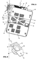
- FIG. 1 shows a charger 1 according to the invention with an outer housing 19 in which two electrical contact devices 2, 2 'are arranged.
- the number of contact devices 2, 2 ' is purely exemplary, so that the charger can of course also have only one or more than two contact devices.
- Each of the two Contact devices 2, 2 ' comprises a first recess 23 and a second recess 24, each in the form of a recess, which have different diameters and shapes. As a result of these different shapes, accumulators having different external shapes can be connected to the charger 1 and charged.
- Recess 24 is substantially rectangular in shape, while recess 24 has a rounded, substantially oval shape.
- Recess 24 is arranged in recess 23, so that the contact devices 2, 2 'have a stepped construction.
- a narrow web 25 each surrounds three sides of the two contact devices 2, 2 '.
- the accumulator 100 consists of a housing 95, which is preferably made of plastic and which encloses a body 99, which is at least partially insertable into the recess 23, and an extension 98, which is at least partially insertable into the recess 24.
- a housing 95 which is preferably made of plastic and which encloses a body 99, which is at least partially insertable into the recess 23, and an extension 98, which is at least partially insertable into the recess 24.
- the housing 95 one or more rechargeable battery cells 96 are accommodated.
- extension 98 a plurality of capacitors 94 for covering short-term power peaks and a plurality of electrical contacts 97, for example contact sockets, are arranged on a printed circuit board 93. Lines connect the printed circuit board 93 to the battery cells 96,
- One aspect of the invention relates to the non-contact detection of different accumulators, in particular by means of magnetic sensors (see below). It may be necessary that the accumulators are provided with one or more magnetic elements, as shown by way of example in Figure 5. Magnetic element 90 is received in extension 98 in a bore 92. In order to ensure the clearest possible detection of one or more magnetic parameters, such as the magnetic field strength or the polarity, the magnetic element 90 is mounted as close to the surface of the accumulator 100 and / or projects the magnetic element 90 at least partially into the housing wall of the housing 95 in, so that the housing wall in this area has a smaller wall thickness 95A than in other housing sections.
- the magnetic element 90 can also break through the housing wall, wherein it is then preferably contained in a separate chamber, which is not connected to the interior of the accumulator, so that no contaminants can penetrate into the accumulator.
- the magnetic element 90 can be designed as a magnetizable coil or as a permanent magnet.
- the contact devices 2, 2 'furthermore comprise two electrical contact elements 26, 27, for example in the form of contact pins, which can be connected or connected to a current source 4 via a first connecting device 3. About these two contact elements 26. 27, which was added to the terminal 1 in the contact sockets 97 when connecting the battery 100, the recharging of the battery cells 96 of the accumulator 100 takes place in a well-known catfish.
- a third electrical contact element 28, also exemplified as a contact pin, serves to monitor the temperature of the accumulator 100 during the charging process.
- a temperature sensor is preferably arranged in the interior of the accumulator 100.
- the temperature sensor When connecting the accumulator 100 to the charger 1, the temperature sensor is connected via contact 28 with a temperature evaluation circuit in the interior of the charger 1.
- the temperature evaluation circuit evaluates the signals received from the temperature sensor and responds to the exceeding of a first temperature threshold value or to falling below a second temperature threshold value, for example by emitting an acoustic or visual warning or by interrupting the charging process. In this way, the charging of the accumulator 100 outside a desired temperature range and thus any damage to the accumulator 100 is prevented.
- the temperature sensor is designed as a resistor in the accumulator 100, whose first end is connected to contact 28 and whose second end is connected to ground.
- the contact elements 26, 27 are connected to a charging circuit arranged inside the charging device 1.
- the charging circuit prepares the current flowing from the current source 4 via the first connecting device 3 to the contacts 26, 27 such that it is suitable for charging the accumulators 100, for example by rectifying the charging current, transformation to that from the accumulator 100 required voltage or setting the required amperage.
- the charger 1 preferably has on its front side a display 29 to inform the user about different operating conditions, operating parameters or other relevant data.
- the display 29 is formed in FIGS. 1 and 4 as a light-emitting display which comprises a plurality of illumination means, preferably light-emitting diodes (LEDs).
- LEDs light-emitting diodes
- other known display devices such as LCD displays can be used.
- touch screen can be used.
- buttons can also be used for entering or selecting parameters.
- Display 29 comprises several display areas: A first area 30 with three LEDs indicates that the charger 1 is ready for operation.
- a second region 31, 31 ' is assigned to the respective contact devices 2, 2' and preferably includes an error indicator 32, 32 ', which indicates, for example, the connection of a broken accumulator or a malfunction of the contact devices 2, 2', and a fill level indicator 33, 33 'for showing the progress of the charging process.
- Display 29 is connected in a known manner to circuits inside the charger which receive and process measured values and sensor signals from sensors, detectors, measuring circuits or circuits and correspondingly switch the LEDs of the display areas 30-33, 33 'on or off.
- the charger 1 has a first connection device 3 and a second connection device 5.
- the charger 1 is used to connect the charger 1 and all consumers contained therein, in particular the contact devices 2, 2 'with a power source 4 and is disposed in an opening of the housing 19.
- the second connection device 5 is electrically connected to the first connection device 3 and the housing 19 is also accommodated in an opening.
- the second connection device 5 is designed such that it is electrically connectable to a second device for charging accumulators 1 '(see FIG. 6), so that the second device for charging accumulators 1' via the second connection device 5 is electrically connected to the current source 4 is connectable.
- the first connection device 3 comprises a plurality of step-shaped electrical contacts 6, the second connection device 5 a plurality of sleeve-shaped contacts 7.
- both connection devices 3. 5 can of course consist of all other known forms of contacts, such as pin or socket-shaped contacts, from Spring contacts or from plan contacts. If alternating current is used as the current source 4, the two connection devices 3, 5 have three contacts, which are designed as L, N and PE contacts.
- FIG. 6 schematically shows the connection of two devices for charging accumulators 1, 1 '.
- the charger 1 ' corresponds in construction and function to the charger 1 of Figures 1 and 2, preferably at least the construction of the charger 1' Identical to the charger 1. For reasons of clarity, only one contact device 2 was shown in both chargers 1, 1 '.
- Charger 1 is detachably connected via the first connection device 3 to a power source 4, here in the form of the general power supply network.
- the first connecting device 3, 3 'of each charger 1, 1' is designed so that it can be connected optionally to the power source 4 or to another charger.
- Three lines 34, 35, 36 which are designed as L, N and PE lines, connect the first connection device 3 with the second connection device 5.
- the second connection device 5 is detachably connected to the first connection device 3 'of the charger 1' so that the power supply of the second charger 1 'via the connecting devices 3, 5 and the lines 34-36 takes place.
- the charging circuit (not shown), which may include, among other things, a switching power supply or a transformer.
- Charger 1 ' has three lines 34', 35 ', 36' and a second connection device 5 ', so that another charger can be connected to this charger 1'. In this way, an arbitrarily long chain of chargers can be joined together Power supply Each charger is connected to the previous chargers, ie between the power source 4 and the charger. Each charger is thus the same supply voltage available.
- 38, 38 ' which connect the contact device 2 and optionally further contact devices to the first connection device 3, 3' and the current source 4.
- electrical fuses 39 for current limiting and a switch 40 for opening / closing the connection of the contact device 2 with the connecting device 3 are provided on the lines 37, 37 ', 38, 38'.
- the seemssvordchtitch 3, 3 ', 5, 5' formed so that the joining of the connecting devices 3, 3 ', 5, 5' is a mechanical, in particular a positive or non-positive connection, particularly preferably a plug connection between the first and second device for charging accumulators 1, 1 'can be produced, so that an additional effort is necessary to separate the two chargers 1, 1'.
- the connecting devices 3, 3 ', 5, 5' thus additionally serve as mechanical connecting elements. This will be more advantageous Way an improved cohesion between the chargers 1, 1 'achieved and it can be handled as a unit several interconnected chargers.
- this also makes it possible to provide a connection between the chargers 1, 1 ', in which no outside of the chargers 1, 1' extending cables or lines are needed.
- one of the two connecting devices 3, 5, preferably the second connecting device 5 as a projection, plug or plug element 8 and the other of the two connecting devices 3, 5, preferably the first connecting device 3 as a return, bush or hollow plug-in receptacle 9 for receiving the projection 8 is formed.
- Projection 8 and recess 9 can have specific shapes, for example, be designed as a polygon to increase the mechanical cohesion.
- Plug member 8 and receptacle 9 can be designed as independent, at least partially made of plastic components which are inserted into openings of the housing 19 and secured therein.
- the housing 19 preferably has a projection 11 and a recess 10, wherein one of the two connection devices 3, 5, preferably the second connection device 5 on the projection 11 and the other of the two horrsvorsiichtitch 3, 5, preferably the first connection devices is arranged on the recess 10.
- the recess 10 and the protrusion 11 may be shaped identically or differently, have very different shapes, for example curved, angular or angled shapes, and may be provided on different areas of the housing 19, for example on one of the side walls 42, 43 or on the top and bottom 46 of the housing Charger 1, 1 '.
- a space-saving arrangement is understood in particular to mean an arrangement in which the chargers 1, 1 'have only a small distance from each other or parts of the housings 19 of two chargers 1, 1 touch one another and / or for the connection the chargers 1, 1' no additional, outside the chargers 1, 1 'extending cables or lines are needed.
- the space-saving arrangement of the chargers 1, 1 comprises both their arrangement next to each other, one behind the other and one above the other.
- the first connecting device 3 is arranged at a recess 10, which by a step 41 in a side wall 42 of the housing 19 is formed.
- the side wall 42 thus has over a portion of its length in the region of the step 41 a substantially straight, lower wall portion 42A and a curved or curved, facing away from the lower wall portion 42A upper wall portion 42B.
- the second connection device 5 is arranged on the side wall 42 opposite the side wall 43 of the charger 1 on a projection 11.
- Projection 11 is also formed by a step 44 such that side wall 43 has a substantially straight, lower wall portion 43A and a curved or curved upper wall portion 43B facing away from lower wall portion 43A.
- Projection 11 and recess 10 are thus formed substantially complementary, so that when joining two chargers 1,1 'they intermesh fluently and compactly.
- a plurality of ventilation slots 47 are provided on the rear wall 45 and the bottom 46 of the charger 1.
- An operating element 48 on the rear wall 45 serves to switch the charging device 1 on and off and is connected to the switch 40.
- a first connection device 12 and a second connection device 13 are provided on the underside 46 of the charger.
- the Ranvorrlchtept 12, 13 are used for the mechanical connection of the chargers 1.1 ', they can be designed for example as a plug and / or as a screw connection.
- Connecting element 14 consists of a body 49, which may be elongated, round, rectangular or multi-sided, for example, and serves as a plug-in element which can be inserted into the connecting device 12 designed as a hollow plug-in receptacle, which has substantially the same shape as body 49.
- To the body 49 includes a base 50, which is formed from a frame 51 and an extension 52 having a bore 53. Extension 52 is shaped so that it can be used in connection device 13 and fastened to the charger, for example by means of a screw which passes through the bore 53 and can be screwed into a further bore 54 with internal thread in the charger 1.
- Each charger 1 is associated with a connecting element 14, which is insertable into the Anschlußvorricbtung 12, wherein the connecting device 12 is mounted on the underside 46 of the charger 1 that at least a portion of the extension 52 with the bore 53 via the side wall 42, 43 of the Charger 1 protrudes. If this charger 1 is now connected to a further charger 1 ', extension 52 can be screwed to the connection device 13 of the charger 1'. If the connecting devices 3, 3 ', 5, 5' are also designed as mechanical connecting elements, it is clearly to be ensured that the distances between the first connecting device 3, 3 'and the first connecting device 12 and between the second connecting device 5, 5' and the second connection device 13 are the same.
- the body 49 is formed by connecting element 14 as a hollow body with a cavity 55.
- Cavity 55 has substantially the same shape as the male member 8 of the second connection device 5 and the inner dimensions of the cavity 55 correspond approximately to the outer dimensions of the male member 8.
- Connecting element 14 can thus placed on male member 8 and 44 at level through hole 53 and another hole screwed with internal thread in step 44.
- Connecting element 14 thus additionally serves as a protective cap for the plug member 8, as long as this plug-in member 8 is still no plug-in receptacle 9 of a first connection device 3 'of another charger 1' is connected. If a further charger 1 'is connected, connecting element 14 must be removed from plug-in member 8 and can be used immediately for the mechanical connection of the two chargers 1, 1'.
- FIG. 4 shows, in a partial sectional view, a section through the contact device 2 and underlying areas of the charger 1.
- the contact devices 2, 2 ' are designed such that they are connected or connectable to a power source 4 and that batteries 100 with different charging requirements can be connected .
- the rechargeable batteries with different charging requirements may, for example, require different charging methods or different types of charging currents, in particular different voltages and / or currents. You can, as already described above, additionally be shaped differently.
- Contact device 2 has a housing portion 19 ', which is part of the housing 19 of the charger 1. A part of the housing 19 'forms the bottom 56 of the contact device 2 and the receptacle 24. Below the bottom 56 in the interior of the Charger 1, at least one magnetic sensor 16, 17 is arranged. The one or more magnetic sensors 16, 17 are part of a non-contact identification device 15 for the detection of accumulators with different charging requirements.
- the one or more magnetic sensors 16, 17, which may be formed, for example, as Hall sensors or Rsed contacts, determine in the detection of the accumulator one or more ere magnetic parameters of one or more magnetic elements which are connected to the accumulator.
- FIG. 5 shows by way of example such an accumulator 100 with a magnetic element 90.
- the detected magnetic parameters may preferably be the magnetic polarity, the magnetic field strength or the magnetic field direction. Accordingly, as magnetic sensors 16, 17, sensors are used which detect the presence of a magnetic field or the magnetic polarity or the magnetic field strength or the field direction.
- the distance between the at least one magnetic element 90 and the at least one magnetic sensor 16, 17 should be as small as possible during the identification process.
- the at least one magnetic sensor 16, 17 is arranged as close as possible to the bottom of 56 of the contact device 2.
- the housing 19 'of the contact device 2 has a housing wall 20 with at least a region of a first wall thickness 21 and with a region of a second, smaller wall thickness 22, wherein the at least one magnetic sensor 16, 17 substantially in the region of the second, smaller wall thickness 22 is arranged.
- the structure of the contact device 2 'and optionally further contact devices of the charger 1 and the arrangement of the at least one magnetic sensor 16, 17 are similar to the described construction of the contact device. 2
- a charging circuit is further provided, which is connected to the identificdtionsvofnchtung 15.
- the at least one magnetic sensor 16, 17 can thus forward an identlflkationssignel to the charging circuit upon detection of a magnetic parameter, which processes the charging circuit and uses to detect the different, connectable types of accumulator. If the charging circuit has recognized the accumulator connected to the contact device 2, 2 ', it determines the charging requirement (s) required for this accumulator. It then loads the accumulator according to this charging request, for example with that for this accumulator appropriate charging method or with the appropriate charging current.
- the charging requirements for the different accumulator types can be stored in a memory which is arranged in or connected to the charger 1.
- the identification device 15 directly switches the parameters of the charging circuit, which advantageously requires no microcontroller and no memory.
- a magnetic sensor 16, 17 or a plurality of magnifying sensors 16, 17 of the same or different type can be arranged. If only one magnetic sensor 16, 17 is present, which emits an identification signal in the presence of a magnetic field, then two types of accumulator can be distinguished, one of the two accumulators being provided with a magnetic element and the other accumulator carrying no magnetic element. If the charging circuit receives an identification signal, for example when the magnetic field is detected, it charges the accumulator according to first charging requirements, if it does not receive an identification signal, it charges the accumulator in accordance with second charging requests.
- two accumulators can likewise be distinguished, one of the two accumulators containing a magnetic element whose south pole is directed toward the magnetic sensor 16, 17 when the accumulator is connected to the contact device 2, 2 ', and the second accumulator contains a magnetic element whose north pole is directed to the magnetic sensor 16, 17 when the accumulator is connected to the contact device 2, 2'. If the charger has a plurality of sensors, it is again possible to detect a plurality of types of accumulators in which each sensor emits an identification signal if the polarity of the magnetic element assigned to it is recognizable to it.
- a magnetic sensor 16, 17 is used, which is designed to emit an identification signal as a function of the detected magnetic field strength.
- the advantage of such a sensor is that it has different magnetic field strengths can detect, so that only a sensor is required to distinguish multiple batteries and the accumulators each require only one magnetic element, each magnetic element has a different field strength.
- each contact device 2, 2 ' with a plurality of field strength sensors and each accumulator with a plurality of magnetic elements.
- the magnetic sensor 16, 17 may be designed to emit an identification signal as a function of the detected field direction.
- This type of sensor detects different orientations of field directions, so that here too only one sensor is needed to distinguish between several accumulators.
- a magnet element which is aligned differently on each accumulator is sufficient so that its field direction differs.
- each contact device 2, 2 ' with a plurality of field direction sensors and each accumulator with a plurality of magnetic elements.
- the term magnetic sensor means both individual sensors, for example a Hall sensor or a reed contact, as well as the combination of a plurality of individual sensors into a functional unit, so that they can detect the above-mentioned magnetic parameters.
- the distance between the magnetic sensor 16, 17 and the associated magnetic element of Accumulators smaller than the distance between two adjacent magnetic elements or between two adjacent magnetic sensors 16, 17.
- the distance between a magnetic sensor and its associated magnetic element should preferably be less than 5.0 mm, more preferably equal to or less than 3.0 mm.
- the distance between two magnetic elements and correspondingly between two magnetic sensors 16, 17 should preferably be greater than 8.0 mm, particularly preferably greater than 16.0 mm.
- the magnetic sensors 16, 17 are mounted inside the charger on a carrier device 18, preferably on a circuit board.
- the board is made of carrier and supported elements 57 so that it is located in the immediate vicinity of the bottom 56 of the contact device 2.
- the charging circuit is arranged on the Stromervorrlchtung 18.
- Particularly preferred are further circuits of the charger 1, for example a temperature evaluation circuit for monitoring the temperature of the accumulator 100 or circuits for operating the LEDs of the display 29, and the LEDs of the display 29 are arranged on the support device 18.
- the invention is not limited to the described embodiments, but includes all possible embodiments that do not change the basic, analogous operating principle of the invention. So it is of course also possible to provide a charger having both an identification device to determine a magnetic parameter of a magnet of a battery, as well as an identification device, the change of a magnetic parameter of a magnet is the part of the charging device to recognize.
- the magnetic sensors can also be designed in a known manner so that they continuously emit a signal and that they, if they detect a magnetic parameter, interrupt the Slgnalabgabe, so that according to the invention under the term "identification signal” and the interruption of a continuously pending signal or the "not getting a signal” is understood.
- even subordinate chargers can be connected to each other, for example chargers with a different number of contact devices, with differently shaped or differently sized contact devices, chargers applying different charging methods, etc. It is essential that the connecting devices are designed such that the chargers can be connected to each other, so that the power supply of a charger via the previously arranged charger and thus by a common energy source.
Landscapes
- Engineering & Computer Science (AREA)
- Power Engineering (AREA)
- Charge And Discharge Circuits For Batteries Or The Like (AREA)
Priority Applications (1)
| Application Number | Priority Date | Filing Date | Title |
|---|---|---|---|
| EP06020498A EP1906507A1 (fr) | 2006-09-29 | 2006-09-29 | Dispositif modulaire pour charger des batteries |
Applications Claiming Priority (1)
| Application Number | Priority Date | Filing Date | Title |
|---|---|---|---|
| EP06020498A EP1906507A1 (fr) | 2006-09-29 | 2006-09-29 | Dispositif modulaire pour charger des batteries |
Publications (1)
| Publication Number | Publication Date |
|---|---|
| EP1906507A1 true EP1906507A1 (fr) | 2008-04-02 |
Family
ID=37635840
Family Applications (1)
| Application Number | Title | Priority Date | Filing Date |
|---|---|---|---|
| EP06020498A Withdrawn EP1906507A1 (fr) | 2006-09-29 | 2006-09-29 | Dispositif modulaire pour charger des batteries |
Country Status (1)
| Country | Link |
|---|---|
| EP (1) | EP1906507A1 (fr) |
Cited By (2)
| Publication number | Priority date | Publication date | Assignee | Title |
|---|---|---|---|---|
| NL1038133C2 (nl) * | 2010-07-29 | 2012-01-31 | Martinus Josephus Hanenberg | Inrichting voor het houden van een mobiele telefoon met de mogelijkheid om een of meerdere houders te koppelen terwijl de mobiele telefoon of de mobiele telefoons tegelijkertijd elektrisch opgeladen worden via een stopcontact. |
| DE102008058926B4 (de) | 2008-11-25 | 2022-03-03 | Küster Holding GmbH | Elektromotorische Antriebseinheit für Stellantriebe in Kraftfahrzeug |
Citations (4)
| Publication number | Priority date | Publication date | Assignee | Title |
|---|---|---|---|---|
| US3696283A (en) * | 1970-04-15 | 1972-10-03 | John W Ackley | Modular battery charger |
| EP0485769A2 (fr) * | 1990-11-15 | 1992-05-20 | BSG-Schalttechnik GmbH & Co. KG | Chargeur pour batteries rechargeables |
| US5963014A (en) * | 1998-07-15 | 1999-10-05 | E. Lead Electronic Co., Ltd. | Serially connected charger |
| US6204632B1 (en) * | 1999-09-08 | 2001-03-20 | Selfcharge | Apparatus for charging multiple batteries |
-
2006
- 2006-09-29 EP EP06020498A patent/EP1906507A1/fr not_active Withdrawn
Patent Citations (4)
| Publication number | Priority date | Publication date | Assignee | Title |
|---|---|---|---|---|
| US3696283A (en) * | 1970-04-15 | 1972-10-03 | John W Ackley | Modular battery charger |
| EP0485769A2 (fr) * | 1990-11-15 | 1992-05-20 | BSG-Schalttechnik GmbH & Co. KG | Chargeur pour batteries rechargeables |
| US5963014A (en) * | 1998-07-15 | 1999-10-05 | E. Lead Electronic Co., Ltd. | Serially connected charger |
| US6204632B1 (en) * | 1999-09-08 | 2001-03-20 | Selfcharge | Apparatus for charging multiple batteries |
Cited By (2)
| Publication number | Priority date | Publication date | Assignee | Title |
|---|---|---|---|---|
| DE102008058926B4 (de) | 2008-11-25 | 2022-03-03 | Küster Holding GmbH | Elektromotorische Antriebseinheit für Stellantriebe in Kraftfahrzeug |
| NL1038133C2 (nl) * | 2010-07-29 | 2012-01-31 | Martinus Josephus Hanenberg | Inrichting voor het houden van een mobiele telefoon met de mogelijkheid om een of meerdere houders te koppelen terwijl de mobiele telefoon of de mobiele telefoons tegelijkertijd elektrisch opgeladen worden via een stopcontact. |
Similar Documents
| Publication | Publication Date | Title |
|---|---|---|
| EP1906506B1 (fr) | Dispositif pour charger des accumulateurs | |
| DE10338082A1 (de) | Anzeigeschaltung für die Batterieladung | |
| DE102013207357A1 (de) | Zellkontaktierungssystem für eine elektrochemische Vorrichtung | |
| EP2885800B1 (fr) | Groupe de construction pour un ensemble de fusibles de commutateurs avec dispositif de mesure et porte-fusible pour un groupe de construction ou un ensemble de fusibles de commutateurs | |
| DE102008021407A1 (de) | Batterieüberwachungssystem | |
| DE112014003362T5 (de) | Elektrogerät, einen Elektrostecker mit unverletzlichen Ablesemitteln umfassend, und elektrisches System mit einem solchen Gerät | |
| WO2012084394A1 (fr) | Appareil de terrain comprenant une unité de batterie | |
| EP3560044A1 (fr) | Élément de connexion, boîtier émetteur muni de l'élément de connexion inséré dedans et procédé de production dudit élément de connexion | |
| EP2828672B1 (fr) | Capteur électronique pour batterie | |
| EP1906507A1 (fr) | Dispositif modulaire pour charger des batteries | |
| DE10312483B4 (de) | Lichtbogenverhinderungseinrichtung | |
| EP0263391B1 (fr) | Dispositif pour recevoir, préparer, exploiter et transmettre des signaux électriques | |
| EP0344479A1 (fr) | Indicateur optique de l'état de marche d'un conducteur d'un réseau électrique, qui est inaccessible à cause d'une isolation ou d'un revêtement | |
| DE102021108004B4 (de) | Ladevorrichtung für ein Elektrofahrzeug | |
| EP3402032B1 (fr) | Système d'inspection et/ou de maintenance avec une interface électrique | |
| EP3025827A1 (fr) | Coffret d'outil dote de plusieurs stations de charge | |
| DE102009017807A1 (de) | Ionisator | |
| DE102014009821A1 (de) | Mehrpoliger Kabelverbinder, dessen Komponenten, und deren Herstellung | |
| LU501225B1 (de) | Steckverbinder mit Sensorelement zur Erfassung eines Kriechstroms, Anordnung mit zwei Steckverbindern und Verfahren zur Erkennung eines Kriechstroms in einem Steckverbinder | |
| DE60118431T2 (de) | Elektrischer pol für einen niederspannungs-unterbrecherschalter | |
| EP2913882B1 (fr) | Système de surveillance de batterie, système de batterie avec système de surveillance de batterie et procédé de fonctionnement du système de batterie | |
| DE102020100443B4 (de) | Stromsensor zum Messen eines einzuspeisenden Stroms mit asymmetrisch magnetfelddurchdrungenen Magnetflusssensoren | |
| DE4203304A1 (de) | Alarmanlage mit fremdspannungssteckern zur versorgung und sicherung elektrisch betriebener geraete | |
| EP1280390A2 (fr) | Clé électronique pour véhicule | |
| DE112011100713B4 (de) | Vorrichtung zur lösbaren Befestigung eines Widerstands |
Legal Events
| Date | Code | Title | Description |
|---|---|---|---|
| PUAI | Public reference made under article 153(3) epc to a published international application that has entered the european phase |
Free format text: ORIGINAL CODE: 0009012 |
|
| AK | Designated contracting states |
Kind code of ref document: A1 Designated state(s): AT BE BG CH CY CZ DE DK EE ES FI FR GB GR HU IE IS IT LI LT LU LV MC NL PL PT RO SE SI SK TR |
|
| AX | Request for extension of the european patent |
Extension state: AL BA HR MK YU |
|
| AKX | Designation fees paid | ||
| REG | Reference to a national code |
Ref country code: DE Ref legal event code: 8566 |
|
| STAA | Information on the status of an ep patent application or granted ep patent |
Free format text: STATUS: THE APPLICATION IS DEEMED TO BE WITHDRAWN |
|
| 18D | Application deemed to be withdrawn |
Effective date: 20081003 |