EP1905631A1 - Safety brake device for the panel of a sliding roof - Google Patents
Safety brake device for the panel of a sliding roof Download PDFInfo
- Publication number
- EP1905631A1 EP1905631A1 EP06020258A EP06020258A EP1905631A1 EP 1905631 A1 EP1905631 A1 EP 1905631A1 EP 06020258 A EP06020258 A EP 06020258A EP 06020258 A EP06020258 A EP 06020258A EP 1905631 A1 EP1905631 A1 EP 1905631A1
- Authority
- EP
- European Patent Office
- Prior art keywords
- brake
- brake element
- safety
- cover
- coupling part
- Prior art date
- Legal status (The legal status is an assumption and is not a legal conclusion. Google has not performed a legal analysis and makes no representation as to the accuracy of the status listed.)
- Granted
Links
Images

Classifications
-
- B—PERFORMING OPERATIONS; TRANSPORTING
- B60—VEHICLES IN GENERAL
- B60J—WINDOWS, WINDSCREENS, NON-FIXED ROOFS, DOORS, OR SIMILAR DEVICES FOR VEHICLES; REMOVABLE EXTERNAL PROTECTIVE COVERINGS SPECIALLY ADAPTED FOR VEHICLES
- B60J7/00—Non-fixed roofs; Roofs with movable panels, e.g. rotary sunroofs
- B60J7/02—Non-fixed roofs; Roofs with movable panels, e.g. rotary sunroofs of sliding type, e.g. comprising guide shoes
Definitions
- the invention relates to a safety brake device of a sunroof cover, which is movable along vehicle-fixed guides, with at least one brake element coupled to the cover, which along an associated guide in normal operation together with the cover is moved longitudinally.
- Such safety braking devices are intended to block the extended or at least partially opened cover in the event of an accident abruptly before a large relative displacement to the vehicle. These safety braking devices must respond quickly and above all provide failure-free trip safety.
- a generic safety brake device is from the DE 103 25 327 B3 known, in which a predetermined breaking point is provided in a drive train between the drive and the cover, which is sheared off from a high acceleration value and thus breaks the connection between the cover and drive to release the lid and bring it into engagement with the braking device.
- the invention provides a braking device that can be more easily adapted to the desired release force than that described in the prior art.
- a coupling part which can be moved with the cover and produces a connection between the cover and the brake element is provided in the brake element protrudes and shifts in an abrupt acceleration of the cover relative to the guide in the brake element and this deformed so that the brake element and guide jam.
- the brake element does not break in two parts, but the brake element is so plastically or, preferably, elastically deformed by the protruding into its interior coupling part outwardly, that there is a jamming between the brake element and guide.
- the deadlock does not necessarily have to lead to an exclusively frictional jamming. It is also possible that the guide has recesses into which the deformed part of the braking element extends, so that it can also come to a positive engagement during braking or blocking.
- the coupling part is attached directly to a drive means, in particular a drive cable, of the lid.
- the brake element directly or indirectly the drive means in a guide for the drive means (usually the cable guide) is stuck. It is possible to let the brake element protrude to the drive means. Alternatively, the brake element could displace the coupling member so that it clamps the drive means in its guide.
- the brake element may be useful to provide with a dual function by being a sliding carriage for controlling the movement of the lid at the same time. These slides or sliding slide in the guide rails and control in particular the lever and / or scenes, the raising movement of the lid.
- the preferred embodiment provides that the coupling part has a laterally protruding into the brake element driver section. This driver section then ensures the deformation of the brake element.
- the deformation is achieved, for example, in that the brake element in the vehicle longitudinal direction before and / or behind a driver portion of the coupling part, which projects into the brake element, at least one extension.
- This extension extends in the horizontal displacement of the driver section. This means nothing else than that this extension of the movement of the coupling part due to the inertial forces in an accident in the Way is, so that the driver portion presses against the extension and this and thus deforms the outer wall of the brake member to the outside.
- a good clamping is achieved in that the brake element in front of and / or behind a driver portion of the coupling part, which projects into the brake element, has two opposite extensions, e.g. an upper and a lower extension, so that the braking element is deformed in two opposite directions.
- the coupling part protrude into the brake element such that a clamping in the horizontal direction, transverse to the vehicle longitudinal axis occurs.
- the recess in the brake element is, for example, a slot which is narrowed by at least one extension in front of at least one axial end of the slot in the direction of travel. Behind this extension, the slot widens again.
- the height of the recess in the brake element corresponds in particular to the height of the projecting into the recess MitEnglishabitess the coupling part. Even so, rattling noises are avoided. Furthermore, a good alignment of brake element and coupling part is ensured.
- the coupling part may have a brake rib on its outside facing the guide. This brake rib is located in particular in the region of an extension.
- restoring forces can be formed even without additional parts, e.g. after a full braking are necessary to restore the initial position of the coupling part to the brake element, as may already occur in a full braking a certain clamping effect or should.
- FIG. 1 shows a vehicle roof 10, in particular a roof module, which is provided with a movable cover 12 which can expose and close a roof opening corresponding to the large roof 12 located below it.
- the vehicle roof 10 may be a sliding lift-roof in which the lid may optionally be exposed at its trailing edge and slid under the fixed roof skin behind it, or e.g. a spoiler roof, where the lid can be exposed and moved over the rear, fixed roof skin.
- the lid 12 is guided in lateral guides 14, as is common in the prior art.
- guided sliding carriage 16 are preferably provided in the lid, with which the cover 12 is coupled directly or indirectly and control the movement of the lid in the vertical and horizontal directions, for example via lever or slide guides.
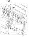
- FIG. 2 shows a U-shaped guide 14.
- this guide 14 runs a sliding carriage 16, which consists of plastic material, preferably even exclusively of plastic material.
- This sliding carriage 16 is elongated and has a link K, via which the opening movement of the lid 12 is controlled at its rear edge.
- the guide 14 has at the upper ends of its two legs an F-shaped configuration, so that on each two rails 17, a left and right guide 18 and 19 results, in each of which an extension 20 of the slide 16 projects. For the left guide 18 of the corresponding boom is not visible.
- the sliding carriage 16 has in the region of its upper end a molded attachment, which is referred to as a braking element 22.
- the brake element 22 may be integral with the sliding carriage 16, so form part of the same, or the sliding carriage 16 may be made in several pieces, wherein a part forms the brake element 22.
- the brake element 22 also protrudes at least partially between the rails 17 of the guide 19th
- a horizontally extending elongated slot 24 in the brake element 22 serves to receive a coupling part 26, which is directly connected to a drive means 28 in the form of a rope, which is guided in a corresponding cable guide 30 pressure-rigid in the guide 14.
- This drive means 28 is driven by an electric motor and moves all sliding carriage, which are responsible for controlling the movement of the lid 12.
- the coupling part 26 is molded in particular from plastic and directly onto the drive means 28.
- a metal version is of course possible.
- a driver portion 32 from which is adapted in its height H and its shape the height H of the slot 24, projects into this and almost completely fills it.
- the slot 24 is narrowed by vertical and integrally formed on top of the brake element 22 extensions 34 project with rounded or trapezoidal cross-section in the slot 24 and thus the displacement of the driver portion 32 from above and below.
- these extensions 34 are spaced from the axial direction in the direction of travel of the elongated hole 24, so that the slot 24 expands once again between the extensions 34 and the corresponding axial end to its original height.
- the driver portion 32 has axially rounded ends, which may also be wedge-shaped.
- the brake element 22 in the region of the extensions 34 has upwardly projecting brake ribs 36.
- braking devices are provided in the rest.
- the brake element 22 may be either itself, e.g. via a boom or via the coupling part 26, exert a lateral force on the drive means 28 so that it is clamped in the cable guide 30 in an accident.
- the elongated hole 24 or the extensions 34 could be seen in plan view describe an outwardly tapered wedge, wherein the driver portion 32 would also be designed as, in plan view, triangular wedge. In a relative movement then the brake element 22 would bulge on the one hand up and down due to the displacement of the driver portion 32, and on the other hand, the cam portion 32 would be urged due to the wedge in the direction of cable guide 30 to clamp the rope therein.
Abstract
Description
Die Erfindung betrifft eine Sicherheits-Bremsvorrichtung eines Schiebedachdeckels, der längs fahrzeugfester Führungen verfahrbar ist, mit wenigstens einem mit dem Deckel gekoppelten Bremselement, das längs einer zugeordneten Führung im Normalbetrieb zusammen mit dem Deckel längs verfahrbar ist.The invention relates to a safety brake device of a sunroof cover, which is movable along vehicle-fixed guides, with at least one brake element coupled to the cover, which along an associated guide in normal operation together with the cover is moved longitudinally.
Solche Sicherheits-Bremsvorrichtungen sollen den ausgefahrenen oder zumindest teilweise geöffneten Deckel bei einem Unfall abrupt vor einer großen Relativverschiebung zum Fahrzeug blockieren. Diese Sicherheits-Bremsvorrichtungen müssen schnell ansprechen und vor allem eine ausfallfreie Auslösesicherheit bieten.Such safety braking devices are intended to block the extended or at least partially opened cover in the event of an accident abruptly before a large relative displacement to the vehicle. These safety braking devices must respond quickly and above all provide failure-free trip safety.
Eine gattungsgemäße Sicherheits-Bremsvorrichtung ist aus der
Die Erfindung schafft eine Bremsvorrichtung, die noch einfacher auf die gewünschte Auslösekraft abgestimmt werden kann als die im Stand der Technik beschriebene.The invention provides a braking device that can be more easily adapted to the desired release force than that described in the prior art.
Hierzu ist bei einer Sicherheits-Bremsvorrichtung der eingangs genannten Art ein mit dem Deckel verfahrbares, eine Verbindung zwischen Deckel und Bremselement herstellendes Koppelungsteil vorgesehen, das in das Bremselement hineinragt und sich bei einer abrupten Beschleunigung des Deckels relativ zur Führung in dem Bremselement verschiebt und dieses so verformt, daß sich Bremselement und Führung verklemmen. Bei der erfindungsgemäßen Bremsvorrichtung bricht das Bremselement nicht in zwei Teile, vielmehr wird das Bremselement durch das in sein Inneres hineinragende Koppelungsteil nach außen so plastisch oder, vorzugsweise, elastisch verformt, daß es zu einer Verklemmung zwischen Bremselement und Führung kommt.For this purpose, in the case of a safety brake device of the type mentioned above, a coupling part which can be moved with the cover and produces a connection between the cover and the brake element is provided in the brake element protrudes and shifts in an abrupt acceleration of the cover relative to the guide in the brake element and this deformed so that the brake element and guide jam. In the brake device according to the invention, the brake element does not break in two parts, but the brake element is so plastically or, preferably, elastically deformed by the protruding into its interior coupling part outwardly, that there is a jamming between the brake element and guide.
Die Verklemmung mußt nicht zwingend zu einer ausschließlich reibschlüssigen Verklemmung führen. Es ist nämlich auch möglich, daß die Führung Vertiefungen aufweist, in die sich der verformte Teil des Bremselements erstreckt, so daß es bei der Bremsung bzw. Blockierung auch zu einem Formschluß kommen kann.The deadlock does not necessarily have to lead to an exclusively frictional jamming. It is also possible that the guide has recesses into which the deformed part of the braking element extends, so that it can also come to a positive engagement during braking or blocking.
Vorzugsweise ist das Koppelungsteil unmittelbar an einem Antriebsmittel, insbesondere einem Antriebsseil, des Deckels angebracht.Preferably, the coupling part is attached directly to a drive means, in particular a drive cable, of the lid.
Um die Verbindung zwischen dem Koppelungsteil und dem Antriebsmittel bei aktivierter Bremsvorrichtung nicht zu hohen Belastungen zu unterwerfen, ist optional angedacht, daß das Bremselement direkt oder indirekt das Antriebsmittel in einer Führung für das Antriebsmittel (normalerweise die Seilführung) klemmt. Dabei ist es möglich, das Bremselement bis zum Antriebsmittel ragen zu lassen. Alternativ könnte das Bremselement das Koppelungsteil verschieben, so daß dieses das Antriebsmittel in seiner Führung klemmt.In order not to subject the connection between the coupling part and the drive means with activated braking device to high loads, it is optionally contemplated that the brake element directly or indirectly the drive means in a guide for the drive means (usually the cable guide) is stuck. It is possible to let the brake element protrude to the drive means. Alternatively, the brake element could displace the coupling member so that it clamps the drive means in its guide.
Ferner kann es sinnvoll sein, das Bremselement mit einer Doppelfunktion zu versehen, indem es gleichzeitig ein Gleitschlitten zur Bewegungssteuerung des Deckels ist. Diese Gleitschlitten oder Gleitelemente gleiten in den Führungsschienen und steuern insbesondere über Hebel und/oder Kulissen die Ausstellbewegung des Deckels.Furthermore, it may be useful to provide the brake element with a dual function by being a sliding carriage for controlling the movement of the lid at the same time. These slides or sliding slide in the guide rails and control in particular the lever and / or scenes, the raising movement of the lid.
Die bevorzugte Ausführungsform sieht vor, daß das Koppelungsteil einen seitlich in das Bremselement ragenden Mitnehmerabschnitt aufweist. Dieser Mitnehmerabschnitt sorgt dann für die Verformung des Bremselements.The preferred embodiment provides that the coupling part has a laterally protruding into the brake element driver section. This driver section then ensures the deformation of the brake element.
Die Verformung wird z.B. dadurch erreicht, daß das Bremselement in Fahrzeuglängsrichtung vor und/oder hinter einem Mitnehmerabschnitt des Koppelungsteils, der in das Bremselement hineinragt, wenigstens einen Fortsatz aufweist. Dieser Fortsatz erstreckt sich in den horizontalen Verschiebeweg des Mitnehmerabschnitts. Das bedeutet nichts anderes als daß dieser Fortsatz der Bewegung des Koppelungsteils aufgrund der Trägheitskräfte bei einem Unfall im Wege steht, so daß der Mitnehmerabschnitt gegen den Fortsatz drückt und diesen und damit die Außenwandung des Bremselements nach außen deformiert.The deformation is achieved, for example, in that the brake element in the vehicle longitudinal direction before and / or behind a driver portion of the coupling part, which projects into the brake element, at least one extension. This extension extends in the horizontal displacement of the driver section. This means nothing else than that this extension of the movement of the coupling part due to the inertial forces in an accident in the Way is, so that the driver portion presses against the extension and this and thus deforms the outer wall of the brake member to the outside.
Eine gute Klemmung wird dadurch erreicht, daß das Bremselement vor und/oder hinter einem Mitnehmerabschnitt des Koppelungsteils, welcher in das Bremselement hineinragt, zwei gegenüberliegende Fortsätze aufweist, z.B. einen oberen und einen unteren Fortsatz, so daß das Bremselement in zwei entgegengesetzte Richtungen verformt wird. Alternativ kann das Koppelungsteil derart in das Bremselement hineinragen, daß eine Klemmung in horizontaler Richtung, quer zur Fahrzeuglängsachse, erfolgt.A good clamping is achieved in that the brake element in front of and / or behind a driver portion of the coupling part, which projects into the brake element, has two opposite extensions, e.g. an upper and a lower extension, so that the braking element is deformed in two opposite directions. Alternatively, the coupling part protrude into the brake element such that a clamping in the horizontal direction, transverse to the vehicle longitudinal axis occurs.
Wenn der Fortsatz unmittelbar an den Mitnehmerabschnitt angrenzt, wird die Relativbewegung zwischen Bremselement und Koppelungsteil sehr gering. Darüber hinaus werden Klappergeräusche bei normalem Fahrbetrieb verhindert.If the extension immediately adjacent to the driver portion, the relative movement between the brake element and coupling part is very low. In addition, rattling noises are prevented during normal driving.
Die Ausnehmung im Bremselement ist beispielsweise ein Langloch, welches vor wenigstens einem in Fahrtrichtung axialen Ende des Langlochs durch den wenigstens einen Fortsatz eingeengt wird. Hinter diesem Fortsatz weitet sich das Langloch wieder auf.The recess in the brake element is, for example, a slot which is narrowed by at least one extension in front of at least one axial end of the slot in the direction of travel. Behind this extension, the slot widens again.
Die Höhe der Ausnehmung im Bremselement entspricht insbesondere der Bauhöhe des in die Ausnehmung hineinragenden Mitnehmabschnitts des Koppelungsteils. Auch damit werden Klappergeräusche vermieden. Ferner ist eine gute Ausrichtung von Bremselement und Koppelungsteil sichergestellt.The height of the recess in the brake element corresponds in particular to the height of the projecting into the recess Mitnehmabschnitts the coupling part. Even so, rattling noises are avoided. Furthermore, a good alignment of brake element and coupling part is ensured.
Um die Klemmwirkung zu verbessern, kann das Koppelungsteil auf seiner der Führung zugewandten Außenseite eine Bremsrippe aufweisen. Diese Bremsrippe liegt insbesondere im Bereich eines Fortsatzes.In order to improve the clamping effect, the coupling part may have a brake rib on its outside facing the guide. This brake rib is located in particular in the region of an extension.
Eine leichte Herstellbarkeit des Bremselements wird erreicht, wenn dieses aus Kunststoff ausgebildet ist. Bei dieser Ausführung lassen sich auch ohne Zusatzteile Rückstellkräfte bilden, die z.B. nach einer Vollbremsung nötig sind, um die Ausgangslage des Koppelungsteils zum Bremselement wieder herzustellen, da möglicherweise bereits bei einer Vollbremsung eine gewisse Klemmwirkung auftreten kann oder soll.Easy manufacturability of the braking element is achieved if this is made of plastic. In this embodiment, restoring forces can be formed even without additional parts, e.g. after a full braking are necessary to restore the initial position of the coupling part to the brake element, as may already occur in a full braking a certain clamping effect or should.
Weitere Merkmale und Vorteile der Erfindung ergeben sich aus der nachfolgenden Beschreibung und aus den nachfolgenden Zeichnungen, auf die Bezug genommen wird. In den Zeichnungen zeigen:
- Figur 1 eine Draufsicht auf ein Fahrzeugschiebedach mit einem Deckel, der über eine erfindungsgemäße Sicherheits-Bremsvorrichtung gesichert ist, und
- Figur 2 eine perspektivische Schnittansicht durch die Führung eines Deckels im Bereich der erfindungsgemäßen Bremsvorrichtung.
- Figure 1 is a plan view of a vehicle sunroof with a lid which is secured by a safety brake device according to the invention, and
- 2 shows a perspective sectional view through the guide of a cover in the region of the braking device according to the invention.
In Figur 1 ist ein Fahrzeugdach 10, insbesondere ein Dachmodul, dargestellt, das mit einem verfahrbaren Deckel 12 versehen ist, der eine dem Deckel 12 entsprechend große, unter ihm liegende Dachöffnung freilegen und schließen kann.FIG. 1 shows a
Das Fahrzeugdach 10 kann ein Schiebe-Hebe-Dach sein, bei dem der Deckel an seiner Hinterkante wahlweise ausgestellt und unter die hinter ihm liegende feste Dachhaut verschoben werden kann, oder z.B. ein Spoilerdach, bei dem der Deckel ausgestellt und über die hintere, feststehende Dachhaut verschoben werden kann.The
Der Deckel 12 wird in seitlichen Führungen 14 geführt, wie es im Stand der Technik üblich ist. Hierzu sind vorzugsweise im Deckel geführte Gleitschlitten 16 vorgesehen, mit denen der Deckel 12 direkt oder indirekt gekoppelt ist und die beispielsweise über Hebel- oder Kulissenführungen die Bewegung des Deckels in vertikaler und horizontaler Richtung steuern.The
In Figur 2 ist eine U-förmige Führung 14 dargestellt. In dieser Führung 14 läuft ein Gleitschlitten 16, der aus Kunststoffmaterial besteht, vorzugsweise sogar ausschließlich aus Kunststoffmaterial. Dieser Gleitschlitten 16 ist langgestreckt und hat eine Kulisse K, über die die Ausstellbewegung des Deckels 12 an seinem hinteren Rand gesteuert wird.FIG. 2 shows a U-shaped
Die Führung 14 hat an den oberen Enden ihrer beiden Schenkel eine F-förmige Gestalt, so daß sich über je zwei Schienen 17 eine linke und rechte Führung 18 bzw. 19 ergibt, in die jeweils ein Ausläufer 20 des Gleitschlittens 16 ragt. Für die linke Führung 18 ist der entsprechende Ausleger nicht zu sehen.The
Der Gleitschlitten 16 hat im Bereich seines oberen Endes einen angeformten Aufsatz, der als Bremselement 22 bezeichnet wird. Das Bremselement 22 kann einstückig mit dem Gleitschlitten 16 ausgeführt sein, also Teil desselben bilden, oder der Gleitschlitten 16 kann mehrstückig ausgeführt sein, wobei ein Teil das Bremselement 22 bildet.The sliding
Das Bremselement 22 ragt ebenfalls zumindest teilweise zwischen die Schienen 17 der Führung 19.The
Ein in horizontaler Richtung gestreckt verlaufendes Langloch 24 im Bremselement 22 dient zur Aufnahme eines Koppelungsteils 26, das unmittelbar mit einem Antriebsmittel 28 in Form eines Seiles verbunden ist, welches in einer entsprechenden Seilführung 30 drucksteif in der Führung 14 geführt wird. Dieses Antriebsmittel 28 wird durch einen Elektromotor angetrieben und bewegt sämtliche Gleitschlitten, die für die Steuerung der Bewegung des Deckels 12 verantwortlich sind.A horizontally extending
Das Koppelungsteil 26 ist insbesondere aus Kunststoff und unmittelbar auf das Antriebsmittel 28 angespritzt. Auch eine Metallausführung ist natürlich möglich. Vom Koppelungsteil 26 steht seitlich ein Mitnehmerabschnitt 32 ab, der in seiner Höhe H und seiner Form der Höhe H des Langlochs 24 angepaßt ist, in dieses ragt und es fast komplett ausfüllt. In Fahrtrichtung R vor und hinter dem Mitnehmerabschnitt 32 wird das Langloch 24 verengt, indem von oben und unten vertikale, einstückig an das Bremselement 22 angeformte Fortsätze 34 mit gerundetem oder trapezförmigem Querschnitt in das Langloch 24 und damit den Verschiebeweg des Mitnehmerabschnitts 32 ragen. Diese Fortsätze 34 sind aber von den in Fahrtrichtung axialen Enden des Langlochs 24 beabstandet, so daß sich das Langloch 24 jeweils zwischen den Fortsätzen 34 und dem entsprechenden axialen Ende noch einmal zu seiner ursprünglichen Höhe aufweitet. Der Mitnehmerabschnitt 32 hat axial abgerundete Enden, die aber auch keilförmig verlaufen können.The
Die in Figur 2 gezeigte Anordnung mit der Führung 14, dem Gleitschlitten 16 und seinem Bremselement 22 sowie dem Koppelungsteil 26 bildet eine Sicherheits-Bremsvorrichtung für den Deckel 12. Diese Bremsvorrichtung soll bei einem Unfall den Deckel 12 relativ zur Führung 14 lagesichern.The arrangement shown in Figure 2 with the
Im nicht ausgelöstem Zustand der Bremsvorrichtung, bei ganz normalem Fahrbetrieb und auch während der Ausstell- und Verfahrbewegungen des Deckels 12 liegen die Fortsätze 34 an dem Mitnehmerabschnitt 32 an.In the non-triggered state of the braking device, during normal driving and also during the raising and traversing movements of the
Bei einem Unfall (insbesondere Frontalaufprall oder Heckaufprall), oder gegebenenfalls auch bei einer Vollbremsung kommt es aufgrund der großen trägen Masse des Deckels 12 bei feststehendem Antriebsmittel 26 und feststehendem Gleitschlitten 16 zu einer Relativbewegung zwischen diesen Teilen. Der Deckel 12 nimmt dabei das Antriebsmittel 28 und dieses wiederum das Koppelungsteil 26 mit. Der Mitnehmabschnitt 32 fährt gegen die Fortsätze 34 auf der entsprechenden Seite und schiebt sich zwischen diese. Dadurch wird das Bremselement 22 in vertikaler Richtung, vorzugsweise plastisch, verformt und beult nach oben und nach unten aus. Dadurch verklemmt sich das Bremselement 22 in der rechten Führung 19, so daß keine weitere Bewegung des Gleitschlittens 16 und damit auch des Deckels 12 mehr möglich ist.In an accident (especially frontal impact or rear impact), or possibly even during full braking, it comes due to the large inertial mass of the
Zur Verbesserung der Klemmwirkung besitzt das Bremselement 22 im Bereich der Fortsätze 34 nach oben ragende Bremsrippen 36. An den beiden seitlichen Führungen 14 sind im übrigen Bremsvorrichtungen vorgesehen.To improve the clamping action, the
Wenn die Belastung zwischen dem Antriebsmittel 28 und dem Koppelungsteil 26 beim Blockieren des Bremselementes 22 zu hoch werden sollte, könnte das Antriebsmittel 28 samt Deckel ungebremst durchrutschen. Deshalb ist auf die Verbindung zwischen Antriebsmittel 28 und Koppelungsteil 26 besonders zu achten. Als zusätzliche Sicherung kann das Bremselement 22 entweder selbst, z.B. über einen Ausleger oder über das Koppelungsteil 26, eine seitliche Kraft auf das Antriebsmittel 28 ausüben, so daß dieses in der Seilführung 30 bei einem Unfall geklemmt wird. Hierzu könnten beispielsweise das Langloch 24 oder die Fortsätze 34 in Draufsicht gesehen einen nach außen zulaufenden Keil beschreiben, wobei der Mitnehmerabschnitt 32 ebenfalls als, in Draufsicht, dreiecksförmiger Keil ausgeführt wäre. Bei einer Relativbewegung würde dann das Bremselement 22 einerseits nach oben und unten aufgrund der Verschiebung des Mitnehmerabschnitts 32 ausbauchen, und auf der anderen Seite würde der Mitnehmerabschnitt 32 aufgrund des Keils in Richtung Seilführung 30 gedrängt werden, um das Seil darin zu klemmen.If the load between the drive means 28 and the
Auch wäre es möglich, den Mitnehmerabschnitt 32 über ein Art Kulisse mit dem Bremselement 32 zu koppeln, so daß eine seitliche Verschiebung des Bremselements 22 relativ zum Koppelungsteil 26 zusätzlich zur Verklemmung des Bremselements 22 in der Führung 19 erfolgt. Diese seitliche Verschiebung kann dann dazu führen, daß das Bremselement 22 z.B. über einen in die Seilführung 30 hineinragenden Fortsatz das Antriebsmittel 28 in der Seilführung 30 klemmt oder daß der Mitnehmerabschnitt 32 mit dem Rest des Koppelungsteils 26 in Richtung Seilführung 30 gedrückt wird, um das Antriebsmittel 28 in der Seilführung 30 zu verkeilen oder verklemmen.It would also be possible to couple the
- 1010
- Fahrzeugdachvehicle roof
- 1212
- Deckelcover
- 14, 18, 1914, 18, 19
- Führungguide
- 1616
- GleitschlittenSliding carriage
- 1717
- Schienenrails
- 2020
- Ausläuferoffshoot
- 2222
- Bremselementbraking element
- 2424
- LanglochLong hole
- 2626
- Koppelungsteilcoupling part
- 2828
- Antriebsmitteldrive means
- 3030
- Seilführungcable guide
- 3232
- Mitnehmerabschnittdriver portion
- 3434
- Fortsätzeprojections
- 3636
- Bremsrippenribs
Claims (15)
wenigstens einem mit dem Deckel (12) gekoppelten Bremselement (22), das längs einer zugeordneten Führung (14, 18, 19) im Normalbetrieb zusammen mit dem Deckel (12) längsverfahrbar ist,
gekennzeichnet durch
ein mit dem Deckel (12) verfahrbares, eine Verbindung zwischen Deckel (12) und Bremselement herstellendes Koppelungsteil (26),
das in das Bremselement (22) hineinragt und sich bei einer abrupten Beschleunigung des Deckels (12) relativ zur Führung (14, 18, 19) in dem Bremselement (22) verschiebt und dieses so verformt, daß sich Bremselement (22) und Führung (14, 18, 19) verklemmen.Safety brake device of a sliding roof cover (12), which is movable along vehicle-fixed guides, with
at least one brake element (22) coupled to the cover (12) and longitudinally displaceable along an associated guide (14, 18, 19) in normal operation together with the cover (12),
marked by
a coupling part (26) which can be moved with the cover (12) and produces a connection between the cover (12) and the brake element,
which projects into the brake element (22) and shifts in an abrupt acceleration of the cover (12) relative to the guide (14, 18, 19) in the brake element (22) and this deformed so that the brake element (22) and guide ( 14, 18, 19) jam.
Priority Applications (4)
| Application Number | Priority Date | Filing Date | Title |
|---|---|---|---|
| EP06020258A EP1905631B1 (en) | 2006-09-27 | 2006-09-27 | Safety brake device for the panel of a sliding roof |
| DE502006006804T DE502006006804D1 (en) | 2006-09-27 | 2006-09-27 | Safety brake device of a sliding roof cover |
| US11/845,800 US7523983B2 (en) | 2006-09-27 | 2007-08-28 | Safety braking device of a sliding roof cover |
| CNA2007101513300A CN101152832A (en) | 2006-09-27 | 2007-09-25 | Safety brake device for the panel of a sliding roof |
Applications Claiming Priority (1)
| Application Number | Priority Date | Filing Date | Title |
|---|---|---|---|
| EP06020258A EP1905631B1 (en) | 2006-09-27 | 2006-09-27 | Safety brake device for the panel of a sliding roof |
Publications (2)
| Publication Number | Publication Date |
|---|---|
| EP1905631A1 true EP1905631A1 (en) | 2008-04-02 |
| EP1905631B1 EP1905631B1 (en) | 2010-04-21 |
Family
ID=37769823
Family Applications (1)
| Application Number | Title | Priority Date | Filing Date |
|---|---|---|---|
| EP06020258A Expired - Fee Related EP1905631B1 (en) | 2006-09-27 | 2006-09-27 | Safety brake device for the panel of a sliding roof |
Country Status (4)
| Country | Link |
|---|---|
| US (1) | US7523983B2 (en) |
| EP (1) | EP1905631B1 (en) |
| CN (1) | CN101152832A (en) |
| DE (1) | DE502006006804D1 (en) |
Cited By (3)
| Publication number | Priority date | Publication date | Assignee | Title |
|---|---|---|---|---|
| DE102011102895A1 (en) * | 2011-05-31 | 2012-12-06 | GM Global Technology Operations LLC (n. d. Gesetzen des Staates Delaware) | Retaining device, shading system, motor vehicle and method for this |
| DE102015104788A1 (en) * | 2015-03-27 | 2016-09-29 | Webasto SE | Arrangement for a motor vehicle |
| DE102015115285A1 (en) | 2015-09-10 | 2017-03-16 | Webasto SE | Arrangement for a movable roof element for a motor vehicle and system for a motor vehicle |
Families Citing this family (3)
| Publication number | Priority date | Publication date | Assignee | Title |
|---|---|---|---|---|
| CN102806833A (en) * | 2011-06-02 | 2012-12-05 | 解志磊 | Power unit of new-energy coach |
| DE102011112262A1 (en) | 2011-09-02 | 2013-03-07 | GM Global Technology Operations LLC (n. d. Gesetzen des Staates Delaware) | Locking device for a sliding roof arrangement of a motor vehicle |
| DE102014009810B3 (en) * | 2014-07-03 | 2015-12-17 | Webasto SE | Vehicle roof with a lid for selectively opening and closing a roof opening |
Citations (3)
| Publication number | Priority date | Publication date | Assignee | Title |
|---|---|---|---|---|
| EP1044837A2 (en) | 1999-04-14 | 2000-10-18 | CTS Fahrzeug-Dachsysteme GmbH | Vehicle roof provided with a slidable roof element |
| DE10325327B3 (en) * | 2003-06-04 | 2005-03-10 | Webasto Ag Fahrzeugtechnik | Vehicle roof with aperture and cover for ventilation has intended break point between drive and cover, which breaks at set acceleration value |
| DE102004003911A1 (en) * | 2004-01-27 | 2005-08-18 | Adam Opel Ag | Braking element for locking sunshade in road vehicle in place is L-shaped with pivot in corner of L-shape and has profiled surface jamming against profiled surface of guide rail |
Family Cites Families (5)
| Publication number | Priority date | Publication date | Assignee | Title |
|---|---|---|---|---|
| DE2940565C2 (en) * | 1979-10-06 | 1984-07-12 | Webasto-Werk W. Baier GmbH & Co, 8035 Gauting | Sunroof for automobiles |
| DE4031552C2 (en) * | 1990-10-05 | 1994-04-28 | Daimler Benz Ag | Safety device for vehicles, in particular for motor vehicles |
| DE19756020C1 (en) * | 1997-12-17 | 1999-01-07 | Webasto Karosseriesysteme | Sun roof for motor vehicle |
| DE19836849C1 (en) * | 1998-08-14 | 2000-03-09 | Daimler Chrysler Ag | Roof arrangement |
| DE10245929A1 (en) * | 2002-09-30 | 2004-04-08 | Arvinmeritor Gmbh | Assembly consisting of at least one guide rail and a slide, in particular for a sun blind in a motor vehicle |
-
2006
- 2006-09-27 DE DE502006006804T patent/DE502006006804D1/en active Active
- 2006-09-27 EP EP06020258A patent/EP1905631B1/en not_active Expired - Fee Related
-
2007
- 2007-08-28 US US11/845,800 patent/US7523983B2/en not_active Expired - Fee Related
- 2007-09-25 CN CNA2007101513300A patent/CN101152832A/en active Pending
Patent Citations (3)
| Publication number | Priority date | Publication date | Assignee | Title |
|---|---|---|---|---|
| EP1044837A2 (en) | 1999-04-14 | 2000-10-18 | CTS Fahrzeug-Dachsysteme GmbH | Vehicle roof provided with a slidable roof element |
| DE10325327B3 (en) * | 2003-06-04 | 2005-03-10 | Webasto Ag Fahrzeugtechnik | Vehicle roof with aperture and cover for ventilation has intended break point between drive and cover, which breaks at set acceleration value |
| DE102004003911A1 (en) * | 2004-01-27 | 2005-08-18 | Adam Opel Ag | Braking element for locking sunshade in road vehicle in place is L-shaped with pivot in corner of L-shape and has profiled surface jamming against profiled surface of guide rail |
Cited By (5)
| Publication number | Priority date | Publication date | Assignee | Title |
|---|---|---|---|---|
| DE102011102895A1 (en) * | 2011-05-31 | 2012-12-06 | GM Global Technology Operations LLC (n. d. Gesetzen des Staates Delaware) | Retaining device, shading system, motor vehicle and method for this |
| DE102015104788A1 (en) * | 2015-03-27 | 2016-09-29 | Webasto SE | Arrangement for a motor vehicle |
| DE102015115285A1 (en) | 2015-09-10 | 2017-03-16 | Webasto SE | Arrangement for a movable roof element for a motor vehicle and system for a motor vehicle |
| WO2017041970A1 (en) * | 2015-09-10 | 2017-03-16 | Webasto SE | Arrangement for a movable roof element for a motor vehicle and system for a motor vehicle |
| US10421342B2 (en) | 2015-09-10 | 2019-09-24 | Webasto SE | Arrangement for a movable roof element for a motor vehicle and system for a motor vehicle |
Also Published As
| Publication number | Publication date |
|---|---|
| US7523983B2 (en) | 2009-04-28 |
| DE502006006804D1 (en) | 2010-06-02 |
| US20080073944A1 (en) | 2008-03-27 |
| EP1905631B1 (en) | 2010-04-21 |
| CN101152832A (en) | 2008-04-02 |
Similar Documents
| Publication | Publication Date | Title |
|---|---|---|
| EP3482024B1 (en) | Handle device with a surface-flush handle | |
| EP1802510B1 (en) | Adjustable steering column pertaining to a motor vehicle | |
| EP1747117B1 (en) | Blind system comprising a braked sliding element | |
| DE602005000502T2 (en) | Vehicle pedal support | |
| EP2171189B1 (en) | Locking device for the bonnet of a motor vehicle | |
| EP3157800B1 (en) | Steering column for a motor vehicle | |
| EP2512899A1 (en) | Steering column for a motor vehicle | |
| WO2010094050A1 (en) | Steering column for a motor vehicle | |
| EP1905631B1 (en) | Safety brake device for the panel of a sliding roof | |
| EP3774496A1 (en) | Steering column for a motor vehicle | |
| EP1433687A2 (en) | Steering column | |
| DE102007056277A1 (en) | Hinge for engine bonnet of motor vehicle i.e. passenger car, has straight-line guide section fastened to bonnet-sided fastening section and inserted into body-sided fastening section in slidingly movable manner | |
| EP3401143A1 (en) | Drive system for a moveable roof section of a motor vehicle spoiler roof module | |
| DE102016220532A1 (en) | Steering column with energy absorption device for a motor vehicle | |
| DE10201899A1 (en) | Reverse shift prevention mechanism for automotive control pedals | |
| DE102017107034A1 (en) | Steering column with energy absorption device | |
| DE102011117798A1 (en) | Safety device for use in vehicle i.e. motor car, to receive collision force during head-on collision, has crash element positively held at vehicle column in direction transverse to longitudinal extension of element during event of crash | |
| DE102006051488A1 (en) | sunroof | |
| DE102018208535A1 (en) | Energy absorption device for a steering column, steering column and a method for operating a steering column | |
| EP3347222B1 (en) | Vehicle roof comprising a mobile roof element | |
| DE102017110868A1 (en) | steering column assembly | |
| WO2017041970A1 (en) | Arrangement for a movable roof element for a motor vehicle and system for a motor vehicle | |
| DE102009021579A1 (en) | Steering column for a motor vehicle | |
| DE10343399B3 (en) | Steering column unit for motor vehicle has steering column connected to bracket via bracket slide and has operating element to release and lock clamps | |
| DE102011115403A1 (en) | Safety device for vehicle i.e. passenger car, has cable whose end is automatically connected with vehicle body or with front flap before or during starting of transferring of front flap from closed position to lifted position |
Legal Events
| Date | Code | Title | Description |
|---|---|---|---|
| PUAI | Public reference made under article 153(3) epc to a published international application that has entered the european phase |
Free format text: ORIGINAL CODE: 0009012 |
|
| AK | Designated contracting states |
Kind code of ref document: A1 Designated state(s): AT BE BG CH CY CZ DE DK EE ES FI FR GB GR HU IE IS IT LI LT LU LV MC NL PL PT RO SE SI SK TR |
|
| AX | Request for extension of the european patent |
Extension state: AL BA HR MK YU |
|
| 17P | Request for examination filed |
Effective date: 20080930 |
|
| 17Q | First examination report despatched |
Effective date: 20081107 |
|
| AKX | Designation fees paid |
Designated state(s): DE FR NL |
|
| GRAP | Despatch of communication of intention to grant a patent |
Free format text: ORIGINAL CODE: EPIDOSNIGR1 |
|
| GRAS | Grant fee paid |
Free format text: ORIGINAL CODE: EPIDOSNIGR3 |
|
| GRAA | (expected) grant |
Free format text: ORIGINAL CODE: 0009210 |
|
| AK | Designated contracting states |
Kind code of ref document: B1 Designated state(s): DE FR NL |
|
| REF | Corresponds to: |
Ref document number: 502006006804 Country of ref document: DE Date of ref document: 20100602 Kind code of ref document: P |
|
| REG | Reference to a national code |
Ref country code: NL Ref legal event code: T3 |
|
| PLBE | No opposition filed within time limit |
Free format text: ORIGINAL CODE: 0009261 |
|
| STAA | Information on the status of an ep patent application or granted ep patent |
Free format text: STATUS: NO OPPOSITION FILED WITHIN TIME LIMIT |
|
| RAP2 | Party data changed (patent owner data changed or rights of a patent transferred) |
Owner name: ROOF SYSTEMS GERMANY GMBH |
|
| 26N | No opposition filed |
Effective date: 20110124 |
|
| PGFP | Annual fee paid to national office [announced via postgrant information from national office to epo] |
Ref country code: FR Payment date: 20121001 Year of fee payment: 7 |
|
| PGFP | Annual fee paid to national office [announced via postgrant information from national office to epo] |
Ref country code: NL Payment date: 20120924 Year of fee payment: 7 |
|
| REG | Reference to a national code |
Ref country code: NL Ref legal event code: V1 Effective date: 20140401 |
|
| REG | Reference to a national code |
Ref country code: FR Ref legal event code: ST Effective date: 20140530 |
|
| PG25 | Lapsed in a contracting state [announced via postgrant information from national office to epo] |
Ref country code: NL Free format text: LAPSE BECAUSE OF NON-PAYMENT OF DUE FEES Effective date: 20140401 Ref country code: FR Free format text: LAPSE BECAUSE OF NON-PAYMENT OF DUE FEES Effective date: 20130930 |
|
| PGFP | Annual fee paid to national office [announced via postgrant information from national office to epo] |
Ref country code: DE Payment date: 20150922 Year of fee payment: 10 |
|
| REG | Reference to a national code |
Ref country code: DE Ref legal event code: R119 Ref document number: 502006006804 Country of ref document: DE |
|
| PG25 | Lapsed in a contracting state [announced via postgrant information from national office to epo] |
Ref country code: DE Free format text: LAPSE BECAUSE OF NON-PAYMENT OF DUE FEES Effective date: 20170401 |