EP1905619A2 - Vehicle suspension - Google Patents
Vehicle suspension Download PDFInfo
- Publication number
- EP1905619A2 EP1905619A2 EP07253793A EP07253793A EP1905619A2 EP 1905619 A2 EP1905619 A2 EP 1905619A2 EP 07253793 A EP07253793 A EP 07253793A EP 07253793 A EP07253793 A EP 07253793A EP 1905619 A2 EP1905619 A2 EP 1905619A2
- Authority
- EP
- European Patent Office
- Prior art keywords
- cylinder head
- head portion
- detecting means
- vehicle
- wheel
- Prior art date
- Legal status (The legal status is an assumption and is not a legal conclusion. Google has not performed a legal analysis and makes no representation as to the accuracy of the status listed.)
- Granted
Links
Images





Classifications
-
- F—MECHANICAL ENGINEERING; LIGHTING; HEATING; WEAPONS; BLASTING
- F16—ENGINEERING ELEMENTS AND UNITS; GENERAL MEASURES FOR PRODUCING AND MAINTAINING EFFECTIVE FUNCTIONING OF MACHINES OR INSTALLATIONS; THERMAL INSULATION IN GENERAL
- F16F—SPRINGS; SHOCK-ABSORBERS; MEANS FOR DAMPING VIBRATION
- F16F9/00—Springs, vibration-dampers, shock-absorbers, or similarly-constructed movement-dampers using a fluid or the equivalent as damping medium
- F16F9/32—Details
- F16F9/3207—Constructional features
- F16F9/3235—Constructional features of cylinders
- F16F9/3242—Constructional features of cylinders of cylinder ends, e.g. caps
-
- B—PERFORMING OPERATIONS; TRANSPORTING
- B62—LAND VEHICLES FOR TRAVELLING OTHERWISE THAN ON RAILS
- B62K—CYCLES; CYCLE FRAMES; CYCLE STEERING DEVICES; RIDER-OPERATED TERMINAL CONTROLS SPECIALLY ADAPTED FOR CYCLES; CYCLE AXLE SUSPENSIONS; CYCLE SIDECARS, FORECARS, OR THE LIKE
- B62K25/00—Axle suspensions
- B62K25/04—Axle suspensions for mounting axles resiliently on cycle frame or fork
-
- F—MECHANICAL ENGINEERING; LIGHTING; HEATING; WEAPONS; BLASTING
- F16—ENGINEERING ELEMENTS AND UNITS; GENERAL MEASURES FOR PRODUCING AND MAINTAINING EFFECTIVE FUNCTIONING OF MACHINES OR INSTALLATIONS; THERMAL INSULATION IN GENERAL
- F16F—SPRINGS; SHOCK-ABSORBERS; MEANS FOR DAMPING VIBRATION
- F16F9/00—Springs, vibration-dampers, shock-absorbers, or similarly-constructed movement-dampers using a fluid or the equivalent as damping medium
- F16F9/32—Details
- F16F9/3292—Sensor arrangements
Definitions
- the groove portion 25c for arrangement of the electrical wiring 22d of the detection device 22 is provided on the lower cylinder head portion 25 whereby the upper cylinder head portion 17 can be fixed to the lower cylinder head portion 25 in a state, in which the electrical wiring 22d is arranged in the groove portion 25c of the lower cylinder head portion 25, after the detection portion 22a of the detection device 22 is inserted into the threaded hole 25a of the lower cylinder head portion 25, so that it is possible to readily perform the work of laying the electrical wiring 22d. Thereby, it is possible to further effectively achieve an improvement in workability at the time of assembly.
- the bladder 62 made of rubber is provided to partition a gas chamber 61d and an oil chamber 61c in the reservoir tank 61 of a rear suspension 60.
- the rear suspension 60 is an example of "suspension device" in the invention.
- the detection device 63 is constructed to be mounted from inside the cylinder portion 64.
- a conical washer 67 is arranged between the C-ring 66 and the flange portion 63b to push the detection device 63 against the lower cylinder head portion 65.
- the detection device 63 is an example of "detecting means” in the invention and the lower cylinder head portion 65 is an example of “cylinder head portion” and “first cylinder head portion” in the invention.
- the conical washer 67 is an example of "push member” in the invention.
Landscapes
- Engineering & Computer Science (AREA)
- General Engineering & Computer Science (AREA)
- Mechanical Engineering (AREA)
- Axle Suspensions And Sidecars For Cycles (AREA)
- Vehicle Body Suspensions (AREA)
- Fluid-Damping Devices (AREA)
Abstract
Description
- The present invention relates to a vehicle, and more particular, to a vehicle provided with a suspension device. The invention also relates to a suspension device for a vehicle.
- Conventionally, there is known a vehicle provided with a hydraulic shock absorber (see, for example, Japanese Utility Model Registration
No. 2585398 Patent Document 1 discloses a vehicle provided with a hydraulic shock absorber, which comprises a bracket for mounting of the hydraulic shock absorber on a vehicle body, a piston rod mounted to the bracket, an electric motor provided in the piston rod, and a length of electrical wiring, which connects between the electric motor and a switch outside the suspension device. The wiring is passed through a through-hole, which extends through the bracket from an upper portion thereof to a side thereof while bending therein, to thereby connect between the electric motor and the switch. - The vehicle disclosed in
Patent Document 1 described above has a disadvantage that the wiring is difficult to pass through a through-hole since the bracket is provided with the through-hole, which extends in the bracket from an upper portion thereof to a side thereof while bending therein. Therefore, there is caused a problem of a decrease in workability at the time of assembly. - One object of an embodiment of the invention is to provide a vehicle provided with a suspension device, which is capable of achieving an improvement in workability at the time of assembly.
- In one aspect of the invention, there is provided a vehicle comprising a wheel, a vehicle body, a suspension device provided between the wheel and the vehicle body to include a damping mechanism, which damps a telescopic force generated when the wheel and the vehicle body move relative to each other, a cylinder body, which accommodates therein the damping mechanism, and a cylinder head portion mounted to the cylinder body, and detecting means, one end portion of which is arranged in the cylinder body and which serves to detect a telescopic state when the wheel and the vehicle body move relative to each other, and wherein the cylinder head portion includes a first cylinder head portion, which closes an end of the cylinder body and which is provided a hole, through which the detecting means passes, and a second cylinder head portion including a mount mounted to one of the wheel and the vehicle body, and fixed to the first cylinder head portion in a manner to cover another portion of the detecting means.
- With the vehicle in one aspect, the cylinder head portion mounted to the cylinder body includes the first cylinder head portion, which closes an end of the cylinder body and which is provided with a hole, into which the detecting means may be inserted during assembly, and a second cylinder head portion fixed to the first cylinder head portion in a manner to cover the other portion of the detecting means, the second cylinder head portion can be fixed to the first cylinder head portion after the detecting means is inserted into the hole of the first cylinder head portion when the detecting means is to be mounted, in a state, in which the other portion of the detecting means is arranged between the first cylinder head portion and the second cylinder head portion. Thereby, there is no need of providing a through-hole, through which the electrical wiring of the detecting means usually provided on the other portion of the detecting means should extend, on the second cylinder head portion. Thereby, unlike the case where a through-hole, through which the electrical wiring of the detecting means should extend, is provided on the whole cylinder head portion composed of the first cylinder head portion and the second cylinder head portion, it is not necessary to perform the work of passing the electrical wiring of the detecting means through a through-hole of the second cylinder head portion, so that it is possible to correspondingly achieve an improvement in workability at the time of assembly.
- With the vehicle in one aspect, preferably, the detecting means includes a detection portion and electrical wiring connected to the detection portion and arranged to extend outside the suspension device, and the electrical wiring is covered by the second cylinder head portion. With such construction, it is possible to readily arrange the electrical wiring so as to have the same covered by the second cylinder head portion.
- With the vehicle in one aspect, preferably, the first cylinder head portion and the second cylinder head portion are fixed together by a plurality of fixing members, such as screw members. With such construction, it is possible to readily and firmly fix the first cylinder head portion and the second cylinder head portion together.
- In this case, preferably, the screw member locations are arranged to be unsymmetrical with respect to a central axis of the cylinder body. With such construction, it is possible to inhibit the second cylinder head portion from being arranged in a position except a predetermined mount position on the first cylinder head portion, so that the second cylinder head portion can be made liable to be arranged in a predetermined mount position on the first cylinder head portion. Thereby, it is possible to further achieve an improvement in workability at the time of assembly.
- In a vehicle, in which the screw members location are arranged to be unsymmetrical with respect to a central axis of the cylinder body, preferably, the first cylinder head portion and the second cylinder head portion are fixed together by three or more screw members and the three or more screw members are arranged so that at least one spacing out of the spacings of the mutually adjacent screw members locations is different from the other spacings. With such construction, it is possible to readily inhibit the second cylinder head portion from being arranged in a position except a predetermined mount position on the first cylinder head portion.
- With the vehicle in one aspect, preferably, a positioning member for positioning of the second cylinder head portion relative to the first cylinder head portion is provided on at least one of the first cylinder head portion and the second cylinder head portion. With such construction, it is possible to readily arrange the second cylinder head portion in a predetermined mount position on the first cylinder head portion. Thereby, it is possible to further achieve an improvement in workability at the time of assembly.
- With the vehicle in one aspect, preferably, a flange portion having a larger, external shape or dimension than that of the remaining portion of the detecting means is provided on the other end of the detection portion of the detecting means. With such construction, the flange portion having a larger, external shape than that of the remaining portion of the detecting means can be inhibited from being inserted into the hole when the detecting means is inserted into the hole of the first cylinder head portion from outside, so that it is possible to inhibit the whole detecting means from entering the hole. Thereby, it is possible to further achieve an improvement in workability at the time of assembly.
- In a vehicle, in which the flange portion is provided on the other end of the detection portion of the detecting means, preferably, a recess, which accommodates therein the flange portion having a larger, external shape than that of the remaining portion of the detecting means, is provided on at least one of the first cylinder head portion and the second cylinder head portion. With such construction, the flange portion having a larger, external shape than that of the remaining portion of the detecting means can be arranged in a recess on at least one of the first cylinder head portion and the second cylinder head portion, so that it is possible to fix the second cylinder head portion to the first cylinder head portion in a manner to cover the other end side of the detection portion of the detecting means. Thereby, it is possible to achieve an improvement in workability at the time of assembly.
- With the vehicle in one aspect, preferably, a groove portion, in which the electrical wiring of the detecting means is arranged, is provided on the first cylinder head portion. With such construction, the second cylinder head portion can be fixed to the first cylinder head portion in a state, in which the electrical wiring is arranged in the groove portion of the first cylinder head portion, after the detecting means is inserted into the hole of the first cylinder head portion, so that it is possible to readily perform the work of laying the electrical wiring. Thereby, it is possible to further effectively achieve an improvement in workability at the time of assembly. In other aspect a groove portion may be provided in the second cylinder head portion.
- With the vehicle in one aspect, preferably, the detecting means includes a first thread portion on an outer periphery of that portion thereof, which is inserted into the insertion hole, the insertion hole of the first cylinder head portion includes a second thread portion, which engages with the first thread portion, and the first thread portion of the detecting means is screwed to the second thread portion of the insertion hole whereby the first thread portion is fixed to the first cylinder head portion. With such construction, the detecting means can be readily fixed to the first cylinder head portion whereby it is possible to achieve an improvement in workability at the time of assembly.
- With the vehicle in one aspect, preferably, the suspension device further includes a push member, which pushes the detecting means against at least one of the first cylinder head portion and the second cylinder head portion. With such construction, the detecting means can be pushed against and fixed to at least one of the first cylinder head portion and the second cylinder head portion, so that it is possible to inhibit the detecting means from shifting after assembly.
- With the vehicle in one aspect, preferably, a sealing member is provided between the insertion hole of the first cylinder head portion and the detecting means. With such construction, it is possible to inhibit an oil in the cylinder body from leaking outside from the insertion hole of the first cylinder head portion.
- With the vehicle in one aspect, preferably, the suspension device further includes a rod portion mounted to the other of the side of the wheel and the side of the vehicle body and extending into the cylinder body, and a piston portion mounted to that portion of the rod portion, which extends into the cylinder body, and the detecting means functions to detect relative positions of that predetermined portion of the detection portion, which is arranged in the cylinder body, and at least one of the rod portion and the piston portion. With such construction, it is possible to use the detecting means to readily detect a telescopic state when the wheel and the vehicle body move relative to each other.
- With the vehicle in one aspect, preferably, the wheel comprises a rear wheel and the suspension device includes a rear suspension arranged between the rear wheel and the vehicle body. In this manner, when the suspension device in one aspect is applied to a rear suspension, it is possible to obtain a vehicle provided with a rear suspension, which is capable of achieving an improvement in workability at the time of assembly.
- The mount of the second cylinder head portion may be mounted to one of a side of the wheel and a side of the vehicle body, or in other aspects may be mounted centrally to one of the wheel or the vehicle.
- In another aspect of the invention there is provided a suspension device for a vehicle having a wheel and a body and being adapted for damping forces generated by relative movement between the wheel and the body, the suspension device including a damping mechanism, a cylinder body, which accommodates the damping mechanism, and a cylinder head portion mounted to the cylinder body, and
detecting means, one end portion of which is arranged in the cylinder body for detecting a condition of the damping mechanism, and
wherein the cylinder head portion includes
a first cylinder head portion, which closes an end of the cylinder body and which is provided with a hole, through which a portion of the detecting means extends, and
a second cylinder head portion including a mount adapted for mounting to one of the wheel and the vehicle body, and fixed to the first cylinder head portion in a manner to cover another portion of the detecting means. - In yet another aspect of the invention there is provided a vehicle comprising a wheel, a vehicle body, a suspension device provided between the wheel and the vehicle body to include a damping mechanism, which damps a telescopic force generated when the wheel and the vehicle body move relative to each other, a cylinder body, which accommodates therein the damping mechanism, and a cylinder head portion mounted to the cylinder body, and detecting means, one end of which is arranged in the cylinder body and which serves to detect a telescopic state when the wheel and the vehicle body move relative to each other, and wherein the cylinder head portion includes a first cylinder head portion, which closes an end of the cylinder body and which is provided with an insertion hole, into which the detecting means is inserted, and a second cylinder head portion including a mount mounted to one of a side of the wheel and a side of the vehicle body, and fixed to the first cylinder head portion in a manner to cover the other end side of the detecting means.
- An embodiment of the invention will be described below with reference to the drawings.
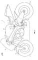
- Fig. 1 is a side view showing a whole construction of a motorcycle according to an embodiment of the invention.
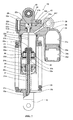
- Fig. 2 is a cross sectional view taken along the line 100-100 in Fig. 4.
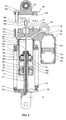
- Fig. 3 is a cross sectional view taken along the line 200-200 in Fig. 4.
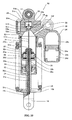
- Fig. 4 is a plan view illustrating a construction of a rear suspension of a motorcycle according to a first embodiment of the invention.
- Fig. 5 is a view illustrating the process of mounting a detection device to the rear suspension of the motorcycle according to the first embodiment of the invention.
- Fig. 6 is a view illustrating the process of mounting a detection device to the rear suspension of the motorcycle according to the first embodiment of the invention.
- Fig. 7 is a cross sectional view illustrating a construction of a rear suspension of a motorcycle according to a second embodiment of the invention.
- Fig. 8 is a plan view illustrating the construction of the rear suspension of the motorcycle according to the second embodiment of the invention.
- Fig. 9 is a view illustrating the process of mounting a detection device to the rear suspension of the motorcycle according to the second embodiment of the invention.
- Fig. 10 is a cross sectional view illustrating a construction of a rear suspension of a motorcycle according to a third embodiment of the invention.
- Fig. 11 is a plan view illustrating the construction of the rear suspension of the motorcycle according to the third embodiment of the invention.
- Fig. 12 is a view illustrating the process of mounting a detection device to the rear suspension of the motorcycle according to the third embodiment of the invention.
- Fig. 13 is a view illustrating a construction of a rear suspension of a motorcycle according to a fourth embodiment of the invention.
- Fig. 1 is a side view showing a whole construction of a motorcycle according to a first embodiment of the invention. Figs. 2 to 4 are views illustrating, in detail, a construction of a rear suspension of the motorcycle, according to the first embodiment, shown in Fig. 1. In addition, the first embodiment is described with respect to a motorcycle as an example of a vehicle of the invention. In the drawings, an arrow FWD indicates the front in a traveling direction of a motorcycle. A construction of the
motorcycle 1 according to the first embodiment of the invention will be described below in detail with reference to Figs. 1 to 4. - With the
motorcycle 1 according to the first embodiment of the invention, amain frame 3 is arranged rearwardly of a head pipe 2 as shown in Fig. 1. Also, a seat rail 4 is connected to themain frame 3. A body frame is constituted by the head pipe 2, themain frame 3, and the seat rail 4. In addition, the head pipe 2, themain frame 3, and the seat rail 4 are an example of "vehicle body" in the invention. - Also, as shown in Fig. 1, a
steering shaft 5 is mounted to the head pipe 2. A handle bar (not shown) is mounted to an upper portion of thesteering shaft 5. Also, a front cowl or fairing 6 is provided forwardly of the head pipe 2 to cover the front of the head pipe 2. Also, a front wheel 7 and a front fender 8 arranged above the front wheel 7 are arranged below the front cowl 6. The front wheel 7 is mounted rotatably to lower ends of a pair of front forks 9. The front forks 9 function to damp a telescopic or compression force generated when the front wheel 7 and the vehicle body move relative to each other. - Also, a
fuel tank 10 is arranged on an upper portion of themain frame 3. Also, aseat 11 is arranged rearwardly of thefuel tank 10. Also, anengine 12 is mounted below themain frame 3. Also, anair cleaner 13 is provided forwardly of theengine 12 to purify an air supplied to theengine 12. Also, a pivot shaft (not shown) is provided rearwardly of themain frame 3. A front end of arear arm 14 is supported by the pivot shaft to be able to swing vertically. Arear wheel 15 is mounted rotatably to a rear end of therear arm 14. In addition, therear wheel 15 is an example of "wheel" in the invention. - Also, a support 3a is provided above a rear portion of the
main frame 3. Amount 17a of an uppercylinder head portion 17, which functions as an upper mount for arear suspension unit 16, is mounted to the support 3a by ashaft member 18. In addition, therear suspension unit 16 is an example of a "suspension device" of an embodiment of the invention and the uppercylinder head portion 17 is an example of "cylinder head portion" and "second cylinder head portion" of an embodiment of the invention. Alower mount 19 of therear suspension unit 16 is mounted to aswing member 20, which is provided to be able to swing about asupport 3b provided below the rear portion of themain frame 3. A lower portion of theswing member 20 is connected to asupport 14a of therear arm 14 by a connectingmember 21. Thereby, as therear arm 14 swings vertically, theswing member 20 swings about thesupport 3b of themain frame 3 and enables therear suspension unit 16 to contract and extend (make a telescopic motion). - Also, in this particular example only one
rear suspension unit 16 is provided. Also, therear suspension unit 16 is provided with adetection device 22, which serves to detect the degree of compression or extension of theunit 16. In the illustrated embodiments parts of theunit 16 translate relative to one another in a telescopic manner and thus the degree of extension or contraction of theunit 16 may be indicated with reference to the telescopic state, and the compression and extension forces experienced by the unit may be expressed in terms of telescopic force. Of course, those of skill in the art will understand that the utility of the present invention is not restricted to telescopic suspension units and that references to, for example, telescopic force or telescopic state are not intended to exclude suspension units which are adapted to extend or contract without parts of the unit moving relative to one another in a telescopic manner, although thedevice 22 of this embodiment senses a telescopic condition of therear suspension 16 as shown in Fig. 2. Thedetection device 22 includes adetection portion 22a formed to be rod-shaped. In addition, thedetection portion 22a comprises a displacement sensor portion, which makes use of a change of a coil in inductance, and functions to detect a length (length corresponding to a particular telescopic condition or amount) of that portion, which is inserted into aninsertion hole 32a of apipe member 32 described later and made of a non-magnetic body. A damping characteristic is controlled by a damping regulation valve (not shown) on the basis of a detected length. - Here, according to the first embodiment, a
flange portion 22b having a larger, external shape than that of the remaining portion of thedetection device 22 and a thread formedportion 22c arranged below theflange portion 22b are provided on the other end of thedetection portion 22a. Also, one end ofelectrical wiring 22d is connected to theflange portion 22b on the other end of thedetection portion 22a. In addition, thedetection device 22 is an example of "detecting means" in the invention and the thread formedportion 22c is an example of "first thread portion" in the invention. - Also, a
cylinder pipe portion 23 having a cylindrical shape is arranged to surround thedetection device 22. In addition, thecylinder pipe portion 23 is an example of "cylinder body" in the invention. Also, aflange portion 23a is fixed to an outer peripheral surface of thecylinder pipe portion 23. Also, alid body 24 having aninsertion hole 24a is mounted to a lower portion of an inner peripheral surface of thecylinder pipe portion 23. Also, provided on an upper portion of thecylinder pipe portion 23 is a lowercylinder head portion 25 formed with a threadedhole 25a, which has a smaller, inside diameter than an outside diameter of theflange portion 22b of thedetection device 22. The lowercylinder head portion 25 and the uppercylinder head portion 17 constitute acylinder head portion 26. In addition, the lowercylinder head portion 25 is an example of "cylinder head portion" and "first cylinder head portion" in the invention and the threadedhole 25a is an example of "insertion hole" and "second thread portion" in the invention. The threadedhole 25a has the same center line as a central axis of thecylinder pipe portion 23 and is provided to permit the thread formedportion 22c of thedetection device 22 to be detachably screwed thereto. In addition, acylinder portion 27 of therear suspension 16 is constituted by thecylinder pipe portion 23, thelid body 24, the lowercylinder head portion 25, and the uppercylinder head portion 17. Also, arecess 25b having a circular-shaped inner peripheral surface is formed above the threadedhole 25a of the lowercylinder head portion 25. Also, a sealingwasher 28 is provided between theflange portion 22b and a bottom surface of therecess 25b. In addition, the sealingwasher 28 is an example of "sealing member" in the invention. The sealingwasher 28 functions to inhibit oil in thecylinder portion 27 from leaking outside. Also, agroove portion 25c is formed on an upper surface of the lowercylinder head portion 25 to extend to an outside surface of the lowercylinder head portion 25 from therecess 25b and to have a depth capable of accommodating theelectrical wiring 22d of thedetection device 22. Thegroove portion 25c enables arranging the other end of theelectrical wiring 22d of thedetection device 22 to extend the same to an outside of therear suspension 16 as shown in Figs. 3 and 4. - Also, according to the first embodiment, the upper
cylinder head portion 17 is fixed to an upper portion of the lowercylinder head portion 25 in a manner to cover an upper end of thedetection portion 22a of thedetection device 22. That is, the uppercylinder head portion 17 is mounted to cover therecess 25b and thegroove portion 25c, in which theelectrical wiring 22d of the lowercylinder head portion 25 is arranged. Also, as shown in Fig. 4, three threadedholes 25d (see Fig. 2) are formed on the lower cylinder head portion 25 (see Fig. 2) to be equally distant from a central axis L1 of the cylinder portion 27 (see Fig. 2) and threescrew insertion holes 17b are formed on the uppercylinder head portion 17 to be positioned corresponding to the three threadedholes 25d of the lowercylinder head portion 25. Threescrew members 29 are inserted into the respective screw insertion holes 17b and then clamped to the respective threadedholes 25d. The three screw members 29 (the threadedholes 25d and thescrew insertion holes 17b) are arranged to be unsymmetrical with respect to the central axis L1 of thecylinder portion 27. That is, as shown in Fig. 4, the three screw members 29 (the threadedholes 25d and the threescrew insertion holes 17b) are arranged so that three intervals, respectively, among the mutually adjacent three screw members 29 (the threadedholes 25d and the threescrew insertion holes 17b) are D1 (about 48 mm), D2 (about 51 mm), and D2 (about 51 mm). That is, the arrangement is such that only one (D1) among the three intervals is different from the remainder. - Also, a
piston portion 30 is arranged in thecylinder portion 27 as shown in Fig. 2. In addition, thepiston portion 30 is an example of "damping mechanism" in the invention. Also, a plurality oforifices piston portion 30. The plurality oforifices 30a function to permit an oil in alower oil chamber 27a below thepiston portion 30 to pass to anupper oil chamber 27b. Also, the plurality oforifices 30b function to permit an oil in theupper oil chamber 27b above thepiston portion 30 to pass to thelower oil chamber 27a disposed below. Also, a plurality of plate-shapedwashers 30c are arranged above the plurality oforifices orifices 30a and open upper surfaces of theorifices 30b. Also, a plurality of plate-shapedwashers 30d are arranged below the plurality oforifices orifices 30a and close lower surfaces of theorifices 30b. - Also, a
rod portion 31 is inserted into and fixed to aninsertion hole 30e of thepiston portion 30. Therod portion 31 is provided with aninsertion hole 31a, into which thedetection portion 22a of thedetection device 22 is inserted. In addition, thecylinder portion 27, thepiston portion 30, and therod portion 31 constitute a damping mechanism of therear suspension 16. Also, anend 31b on that side (upper side) of theinsertion hole 31a of therod portion 31, through which thedetection portion 22a is inserted, is formed to be tapered so that an open width is increased upward. Also, apipe member 32 made of a non-magnetic body and having aninsertion hole 32a, into which the other end of thedetection portion 22a is inserted, is inserted into and fixed to theinsertion hole 31a of therod portion 31. - Also, a threaded
portion 31c provided on an outer periphery of a lower end of therod portion 31 is fixed to a threadedhole 19a of thelower mount 19. Acompression spring 33 is arranged between an upper surface of aflange portion 19b of thelower mount 19 and a lower surface of theflange portion 23a. - Also, a
reservoir tank portion 34 is provided integrally with the lowercylinder head portion 25. Thereservoir tank portion 34 is formed with acylinder portion 34b, which includes apiston portion 34a therein. Also, thecylinder portion 34b is composed of anoil chamber 34c above thepiston portion 34a and agas chamber 34d below thepiston portion 34a. Theoil chamber 34c of thecylinder portion 34b is connected to theupper oil chamber 27b throughoil passages member 36 is provided between theoil passages gas chamber 34d is filled with an air to have an internal pressure of about 1 MPa. - Subsequently, an operation of the
rear suspension 16 of themotorcycle 1 according to the first embodiment will be described with reference to Fig. 2. - First, an explanation is given to the case where a force in a direction of contraction acts on the rear suspension 16 (see Fig. 2). When a force in a direction of contraction acts on the
rear suspension 16, therear suspension 16 is contracted against the bias of the compression spring 33 (see Fig. 2) whereby a damping force is generated. - Specifically, as shown in Fig. 2, when a force in a direction of contraction acts on the
rear suspension 16 and thereby thepiston portion 30 and therod portion 31 rise relative to thecylinder portion 27, oil pressure in theupper oil chamber 27b increases, so that thewashers 30d of thepiston portion 30 are opened. Oil in theupper oil chamber 27b flows through theorifices 30b of thepiston portion 30 in A direction to flow into thelower oil chamber 27a. Also, when oil pressure in theupper oil chamber 27b increases, oil in theupper oil chamber 27b flows into thereservoir tank portion 34 through theoil passages orifices 30b of thepiston portion 30, and a damping force is generated by a dampingmember 36, which is provided between theoil passages - Subsequently, an explanation is given to the case where a force in a direction of extension acts on the
rear suspension 16. When a force in the direction of extension acts on therear suspension 16, therear suspension 16 is extended whereby a damping force is generated. - Specifically, when a force in the direction of extension acts on the
rear suspension 16 and thereby thepiston portion 30 and therod portion 31 descend relative to thecylinder portion 27, oil pressure in thelower oil chamber 27a increases, so that thewashers 30c of thepiston portion 30 are opened. Oil in thelower oil chamber 27a flows through theorifices 30a of thepiston portion 30 in B direction to flow into theupper oil chamber 27b. At this time, since theupper oil chamber 27b is increased in volume, oil in thereservoir tank portion 34 flows into theupper oil chamber 27b through theoil passages orifices 30a of thepiston portion 30, and a damping force is generated by the dampingmember 36, which is provided between theoil passages - Also, when the
rear suspension 16 is contracted or extended, thedetection portion 22a of thedetection device 22 moves relatively in therod portion 31 whereby a change in inductance is generated. Based on a change in inductance, a length (length corresponding to an amount of contraction or extension) of that portion of thedetection portion 22a, which is inserted into theinsertion hole 32a of thepipe member 32 made of a non-magnetic body, is detected, and a desired damping characteristic is obtained by controlling a damping regulation valve (not shown) on the basis of a detected length. - Figs. 5 and 6 are views illustrating a process of assembling the detection device to the rear suspension of the motorcycle according to the first embodiment. Subsequently, the process of assembling the
detection device 22 to therear suspension 16 of themotorcycle 1 according to the first embodiment will be described with reference to Figs. 2 to 6. - First, as shown in Fig. 5, the
detection portion 22a of thedetection device 22 is inserted, from outside (above), into the threadedhole 25a of the lowercylinder head portion 25 and theinsertion hole 32a of thepipe member 32 made of a non-magnetic body and inserted into theinsertion hole 31a of therod portion 31. At this time, the sealingwasher 28 is arranged in a manner to interpose between theflange portion 22b and therecess 25b of the lowercylinder head portion 25. The thread formedportion 22c formed on thedetection device 22 is clamped to the threadedhole 25a. - Subsequently, the
electrical wiring 22d connected to theflange portion 22b is arranged in thegroove portion 25c of the lowercylinder head portion 25 as shown in Fig. 6, and the other end of theelectrical wiring 22d is taken out as shown in Fig. 4. - Thereafter, as shown in Figs. 2 to 4, the three screw insertion holes 17b of the upper
cylinder head portion 17 are arranged corresponding to the three threadedholes 25d of the lowercylinder head portion 25 and fixed by means of the threescrew members 29. In this manner, mounting of thedetection device 22 to therear suspension 16 is completed. - According to the first embodiment, the
cylinder head portion 26 mounted to thecylinder portion 27 is constructed to comprise the lowercylinder head portion 25, which closes one side of thecylinder portion 27 and is provided with the threadedhole 25a, into which thedetection device 22 is inserted, and the uppercylinder head portion 17 fixed to the lowercylinder head portion 25 in a manner to cover the other side of thedetection portion 22a of thedetection device 22, whereby the uppercylinder head portion 17 can be fixed to the lowercylinder head portion 25 after thedetection device 22 is inserted into the threadedhole 25a of the lowercylinder head portion 25 when thedetection device 22 is to be mounted, in a state, in which theelectrical wiring 22d connected to the other end of thedetection portion 22a of thedetection device 22 is arranged between the uppercylinder head portion 17 and the lowercylinder head portion 25. Thereby, there is no need of providing a through-hole, through which theelectrical wiring 22d of thedetection device 22 should extend, on the lowercylinder head portion 25. Thereby, unlike the case where a through-hole, through which theelectrical wiring 22d of thedetection device 22 should extend, is provided on the wholecylinder head portion 26 composed of the uppercylinder head portion 17 and the lowercylinder head portion 25, it is not necessary to perform the work of passing theelectrical wiring 22d of thedetection device 22 through a through-hole of the uppercylinder head portion 17, so that it is possible to correspondingly achieve an improvement in workability at the time of assembly. - Also, according to the first embodiment, the upper
cylinder head portion 17 and the lowercylinder head portion 25 are fixed together by means of the threescrew members 29 and the three screw members 29 (the threadedholes 25d and the threescrew insertion holes 17b) are arranged so that intervals among the mutually adjacent three screw members 29 (the threadedholes 25d and the threescrew insertion holes 17b) are D1 (about 48 mm), D2 (about 51 mm), and D2 (about 51 mm), whereby it is possible to readily inhibit the uppercylinder head portion 17 from being fixed in a position except a predetermined mount position on the lowercylinder head portion 25, so that the uppercylinder head portion 17 can be made liable to be arranged in the predetermined mount position on the lowercylinder head portion 25. Thereby, it is possible to achieve a further improvement in workability at the time of assembly. - Also, according to the first embodiment, the
flange portion 22b having a larger, external shape than that of the remaining portion of thedetection device 22 is provided on the other end of thedetection portion 22a and the threadedhole 25a of the lowercylinder head portion 25 is formed to have a smaller, inside diameter than an outside diameter of theflange portion 22b of thedetection device 22, whereby theflange portion 22b having a larger, external shape than that of the remaining portion of thedetection device 22 can be inhibited from being inserted into the threadedhole 25a when thedetection portion 22a of thedetection device 22 is inserted into the threadedhole 25a of the lowercylinder head portion 25 from outside, so that it is possible to inhibit thewhole detection device 22 from entering the threadedhole 25a. Thereby, it is possible to achieve a further improvement in workability at the time of assembly. - Also, according to the first embodiment, the
groove portion 25c for arrangement of theelectrical wiring 22d of thedetection device 22 is provided on the lowercylinder head portion 25 whereby the uppercylinder head portion 17 can be fixed to the lowercylinder head portion 25 in a state, in which theelectrical wiring 22d is arranged in thegroove portion 25c of the lowercylinder head portion 25, after thedetection portion 22a of thedetection device 22 is inserted into the threadedhole 25a of the lowercylinder head portion 25, so that it is possible to readily perform the work of laying theelectrical wiring 22d. Thereby, it is possible to further effectively achieve an improvement in workability at the time of assembly. - Figs. 7 and 8 are views illustrating, in detail, a construction of a rear suspension of a motorcycle according to a second embodiment of the invention. Unlike the first embodiment, an example is described referring to Figs. 7 and 8, in which according to a second embodiment a
positioning pin 43 is provided for mounting of an uppercylinder head portion 42 in a predetermined position on a lowercylinder head portion 41. - According to the second embodiment, the lower
cylinder head portion 41 having a threadedhole 41a is provided on an upper portion of acylinder pipe portion 23. The threadedhole 41a has the same center line as a central axis of thecylinder pipe portion 23 and is provided to permit a thread formedportion 22c of adetection device 22 to be screwed thereto. In addition, the lowercylinder head portion 41 is an example of "cylinder head portion" and "first cylinder head portion" in the invention and the threadedhole 41a is an example of "insertion hole" and "second threaded portion" in the invention. Also, arecess 41b having a circular-shaped inner peripheral surface is formed above the threadedhole 41a of the lowercylinder head portion 41. Also, agroove portion 41c is formed on an upper surface of the lowercylinder head portion 41 to extend to an outside surface of the lowercylinder head portion 41 from therecess 41b and to have a depth capable of accommodating anelectrical wiring 22d of thedetection device 22. - Also, an upper
cylinder head portion 42 functioning as an upper mount is fixed to an upper portion of the lowercylinder head portion 41. In addition, the uppercylinder head portion 42 is an example of "cylinder head portion" and "second cylinder head portion" in the invention. - Also, according to the second embodiment, as shown in Fig. 8, three threaded
holes 41d (see Fig. 7) are formed on the lower cylinder head portion 41 (see Fig. 7) to be equally distant from a central axis L1 of a cylinder portion 27 (see Fig. 7) and threescrew insertion holes 42a are formed on the uppercylinder head portion 42 to be positioned corresponding to the three threadedholes 41d of the lowercylinder head portion 41. Threescrew members 29 are inserted into the respective thescrew insertion holes 42a and then clamped to the respective threadedholes 41d. Also, as shown in Fig. 8, the three screw members 29 (the threadedholes 41d and the respective threescrew insertion holes 42a) are arranged so that three intervals among the mutually adjacent three screw members 29 (the threadedholes 41d and the respective threescrew insertion holes 42a) become the same distance D3 (about 51 mm). - Here, according to the second embodiment, as shown in Fig. 7, the
positioning pin 43 is provided to position the uppercylinder head portion 42 in a predetermined position on the lowercylinder head portion 41. Thepositioning pin 43 is press fitted into apin hole 41e, into which thepositioning pin 43 provided on the lowercylinder head portion 41 is inserted, and provided so as to project above an upper surface of the lowercylinder head portion 41. Also, the uppercylinder head portion 42 is provided with apin hole 42b, into which thepositioning pin 43 is inserted. In addition, thepositioning pin 43 is an example of "positioning member" in the invention. - In addition, the remaining construction and operation of the second embodiment are the same as the construction of the first embodiment.
- Fig. 9 is a view illustrating a process of mounting the detection device to a rear suspension of a motorcycle according to the second embodiment. Subsequently, the process of mounting the
detection device 22 to therear suspension 40 of the motorcycle according to the second embodiment will be described with reference to Figs. 8 and 9. - According to the second embodiment, as shown in Figs. 8 and 9, after the other end of an
electrical wiring 22d is taken out, the threescrew insertion holes 42a of the uppercylinder head portion 42 are arranged in a manner to correspond to the three threadedholes 41d of the lowercylinder head portion 41. At this time, thepin hole 42b of the uppercylinder head portion 42 is fitted onto thepositioning pin 43 press fitted into thepin hole 41e of the lowercylinder head portion 41. Thereby, the uppercylinder head portion 42 is arranged in a predetermined mount position on the lowercylinder head portion 41. The uppercylinder head portion 42 arranged in the predetermined mount position is fixed to the lowercylinder head portion 41 by means of threescrew members 29. - In addition, the remaining process of assembling the detection device according to the second embodiment is the same as the process of assembling the detection device according to the first embodiment.
- According to the second embodiment, as described above, the
positioning pin 43 for positioning of the uppercylinder head portion 42 on the lowercylinder head portion 41 is provided and thepin hole 42b for insertion thereinto of thepositioning pin 43 is provided on the uppercylinder head portion 42 whereby it is possible to readily arrange the uppercylinder head portion 42 in the predetermined mount position on the lowercylinder head portion 41. - Figs. 10 and 11 are views illustrating, in detail, a construction of a rear suspension of a motorcycle according to a third embodiment of the invention. Unlike the first and second embodiments, an example is described referring to Figs. 10 and 11, in which according to the third embodiment a
detection device 51 is fixed by interposing aconical washer 54 between aflange portion 51b of thedetection device 51 and a lowercylinder head portion 53 and thereby pushing an upper surface of theflange portion 51b against an uppercylinder head portion 55. - According to the third embodiment, a
rear suspension 50 is provided with thedetection device 51, which detects a telescopic amount of therear suspension 50 as shown in Fig. 10. Thedetection device 51 includes adetection portion 51a formed to be rod-shaped. - Here, according to the third embodiment, a
flange portion 51b having a larger, external shape than that of the remaining portion of thedetection device 51 and aninsertion portion 51d arranged below theflange portion 51b and having an O-ring engagement groove 51c are provided on the other end of thedetection portion 51a. An O-ring 52 made of rubber is fitted into the O-ring engagement groove 51c of theinsertion portion 51d. Also, one end of anelectrical wiring 51e is connected to theflange portion 51b. In addition, thedetection device 51 is an example of "detecting means" in the invention and the O-ring 52 is an example of "sealing member" in the invention. - Also, according to the third embodiment, the lower
cylinder head portion 53 having aninsertion hole 53a is provided on an upper portion of acylinder pipe portion 23. Theinsertion hole 53a has the same center line as a central axis of thecylinder pipe portion 23 and is sealed by the O-ring 52 fitted into the O-ring engagement groove 51c of thedetection device 51. In addition, the lowercylinder head portion 53 is an example of "cylinder head portion" and "first cylinder head portion" in the invention. Also, arecess 53b having a circular-shaped inner peripheral surface is formed above theinsertion hole 53a of the lowercylinder head portion 53. Also, theconical washer 54 having a spring function is arranged between therecess 53b and theflange portion 51b. Thereby, an upper surface of theflange portion 51b is pushed against a lower surface of the uppercylinder head portion 55 to be thereby fixed thereto. In addition, the uppercylinder head portion 55 is an example of "cylinder head portion" and "second cylinder head portion" in the invention, and theconical washer 54 is an example of "push member" in the invention. Also, a groove portion 53c is formed on an upper surface of the lowercylinder head portion 53 to extend to an outside surface of the lowercylinder head portion 53 from therecess 53b and to have a depth capable of accommodating theelectrical wiring 51e. - Also, according to the third embodiment, as shown in Fig. 11, three threaded
holes 53d (see Fig. 10) are formed on the lower cylinder head portion 53 (see Fig. 10) to be equally distant from a central axis L1 of a cylinder portion 27 (see Fig. 10) and threescrew insertion holes 55a are formed on the uppercylinder head portion 55 to be positioned corresponding to the three threadedholes 53d. Threescrew members 29 are inserted into the respectivescrew insertion holes 55a and then clamped to the respective threadedholes 53d. The three screw members 29 (the threadedholes 53d and the threescrew insertion holes 55a) are arranged to be unsymmetrical with respect to the central axis L1 of thecylinder portion 27. That is, as shown in Fig. 11, the three screw members 29 (the threadedholes 53d and the threescrew insertion holes 55a) are arranged so that three intervals, respectively, among the mutually adjacent three screw members 29 (the threadedholes 53d and the threescrew insertion holes 55a) are D4 (about 48 mm), D5 (about 51 mm), and D5 (about 51 mm). That is, the arrangement is such that only one (D4) among the three intervals is different from the remainder. - In addition, the remaining construction and operation of the third embodiment are the same as the construction of the first embodiment.
- Fig. 12 is a view illustrating a process of mounting the detection device to a rear suspension of a motorcycle according to the third embodiment. Subsequently, the process of mounting the
detection device 51 to therear suspension 50 of the motorcycle according to the third embodiment will be described with reference to Figs. 11 and 12. - According to the third embodiment, as shown in Fig. 12, the
detection portion 51a of thedetection device 51 with the O-ring 52 fitted into the O-ring engagement groove 51c is inserted, from outside (above), into theinsertion hole 53a of the lowercylinder head portion 53 and theinsertion hole 32a of thepipe member 32 made of a non-magnetic body and inserted into theinsertion hole 31a of therod portion 31. At this time, theconical washer 54 is arranged in a manner to interpose between theflange portion 51b and therecess 53b of the lowercylinder head portion 53. - Subsequently, as shown in Figs. 11 and 12, the
electrical wiring 51e connected to theflange portion 51b is arranged in the groove portion 53c of the lowercylinder head portion 53 and the other end of theelectrical wiring 51e is taken out. - Thereafter, the three
screw insertion holes 55a of the uppercylinder head portion 55 are arranged corresponding to the three threadedholes 53d of the lowercylinder head portion 53 and fixed by means of the threescrew members 29. In this manner, mounting of thedetection device 51 to therear suspension 50 is completed. - According to the third embodiment, by providing the
conical washer 54, which pushes thedetection device 51 against the uppercylinder head portion 55, thedetection device 51 can be pushed against and fixed to the uppercylinder head portion 55 by theconical washer 54, so that it is possible to inhibit thedetection device 51 from shifting after assembly. - Fig. 13 is a view illustrating, in detail, a construction of a rear suspension of a motorcycle according to a fourth embodiment of the invention. Unlike the first, second, and second embodiments, an example is described referring to Fig. 13, in which according to the fourth embodiment a
detection device 63 is mounted from inside acylinder portion 64 and abladder 62 made of rubber is provided in areservoir tank 61. - According to the fourth embodiment, as shown in Fig. 13, the
bladder 62 made of rubber is provided to partition agas chamber 61d and anoil chamber 61c in thereservoir tank 61 of arear suspension 60. In addition, therear suspension 60 is an example of "suspension device" in the invention. Also, thedetection device 63 is constructed to be mounted from inside thecylinder portion 64. - Specifically, a lower
cylinder head portion 65 is provided with aninsertion hole 65a, arecess 65b formed on an underside (inner side of the cylinder portion 64) of the lowercylinder head portion 65, and agroove portion 65c. Thedetection device 63 is inserted into theinsertion hole 65a of the lowercylinder head portion 65 from under (a side toward the cylinder pipe portion 23) and aflange portion 63b is arranged in therecess 65b of the lowercylinder head portion 65. In this case, anengagement groove 65d is provided on the lowercylinder head portion 65 to inhibit thedetection device 63 from shifting and a C-ring 66 is arranged in theengagement groove 65d. Aconical washer 67 is arranged between the C-ring 66 and theflange portion 63b to push thedetection device 63 against the lowercylinder head portion 65. In addition, thedetection device 63 is an example of "detecting means" in the invention and the lowercylinder head portion 65 is an example of "cylinder head portion" and "first cylinder head portion" in the invention. Also, theconical washer 67 is an example of "push member" in the invention. - Also, according to the fourth embodiment, the
groove portion 65c for arrangement of anelectrical wiring 63d of thedetection device 63 is provided on the lowercylinder head portion 65 whereby an uppercylinder head portion 68 can be fixed to the lowercylinder head portion 65 in a state, in which theelectrical wiring 63d is arranged in thegroove portion 65c of the lowercylinder head portion 65, after thedetection device 63 is inserted into theinsertion hole 65a of the lowercylinder head portion 65 from under (a side toward the cylinder pipe portion 23), so that it is possible to readily perform the work of laying theelectrical wiring 63d. Thereby, it is possible to further effectively achieve an improvement in workability at the time of assembly. In addition, the uppercylinder head portion 68 is an example of "cylinder head portion" and "second cylinder head portion" in the invention. - In addition, it should be thought that all the embodiments disclosed herein are exemplary in all respects and not limitative. The scope of the invention is indicated by the claims rather than the foregoing descriptions of the embodiments, and all changes within the meaning and range of equivalence thereof are intended to be embraced therein.
- For example, while the first to fourth embodiments illustrate a motorcycle as an example of a vehicle provided with a suspension device, the invention is not limited thereto but applicable to other vehicles such as bicycle, three-wheeler, ATV (All Terrain Vehicle), etc. as far as the vehicle is provided with a suspension device. Indeed, the suspension device may have utility in a vehicle provided with ground engaging members other than wheels, such as tracks, skids or skis.
- Also, while the first to fourth embodiments illustrate an example, in which the invention is applied to a rear suspension as an example of a suspension device including a damping mechanism, the invention is not limited thereto but applicable to other suspension devices than a rear suspension.
- Also, while the third embodiment illustrates an example, in which a conical washer (push member) is provided on a lower cylinder head portion (first cylinder head), the invention is not limited thereto but a conical washer (push member) may be provided on an upper cylinder head portion (second cylinder head).
-
- 1: motorcycle (vehicle)
- 2: head pipe (vehicle body)
- 3: main frame (vehicle body)
- 4: seat rail (vehicle body)
- 15: rear wheel (wheel)
- 16, 40, 50, 60: rear suspension (suspension device)
- 17, 42, 55, 68: upper cylinder head portion (cylinder head portion, second cylinder head)
- 17a: mount
- 22, 51, 63: detection device (detecting means)
- 22a, 51a, 63a: detection portion
- 22b, 51b, 63b: flange portion
- 22c: thread formed portion (first thread portion)
- 22d, 51d, 63d: electrical wiring
- 25, 41, 53, 65: lower cylinder head portion (cylinder head portion, first cylinder head)
- 25a, 41a: threaded hole (insertion hole, second thread portion) 25b, 41b, 53b, 65b: recess
- 25c, 41c, 53c, 65c: groove portion
- 27: cylinder portion (cylinder body)
- 28: sealing washer (sealing member)
- 29: screw member
- 30: piston portion (damping mechanism)
- 31: rod portion
- 43: positioning pin (positioning member)
- 52: O-ring (sealing member)
- 53a: insertion hole
- 54, 67: conical washer (push member)
Claims (19)
- A vehicle (1) comprising
a wheel (15),
a vehicle body (3),
a suspension device (16) provided between the wheel (15) and the vehicle body (3) to include a damping mechanism (30), which damps a telescopic force generated when the wheel (15) and the vehicle body (3) move relative to each other, a cylinder body (27), which accommodates therein the damping mechanism (30), and a cylinder head portion (26) mounted to the cylinder body (27), and
detecting means (22), one end portion (22a) of which is arranged in the cylinder body (27) and which serves to detect a telescopic state when the wheel (15) and the vehicle body (3) move relative to each other, and
wherein the cylinder head portion (26) includes
a first cylinder head portion (25), which closes an end of the cylinder body (27) and which is provided with a hole (25a), through which the detecting means (22) extends, and
a second cylinder head portion (17) including a mount (170) mounted to one of the wheel (15) and the vehicle body (3), and fixed to the first cylinder head portion (25) in a manner to cover another portion of the detecting means (22b, 22c). - The vehicle according to claim 1, wherein the detecting means (22) includes a detection portion (22a) and
electrical wiring (22d) connected to the other portion of the detection portion (22b, 22c) and arranged to extend outside the suspension device (16), and
at least a portion of the electrical wiring (22d) is covered by the second cylinder head portion (17). - The vehicle of any preceding claim wherein the first and second cylinder head portions (25, 17) are fixed together by one or more fixing members (29).
- The vehicle according to any preceding claim, wherein the first cylinder head portion (25) and the second cylinder head portion (17) are fixed together by a plurality of screw members (29).
- The vehicle according to claim 4, wherein the screw member locations are arranged to be unsymmetrical with respect to a central axis of the cylinder body (L1).
- The vehicle according to claim 5, wherein the first cylinder head portion (25) and the second cylinder head portion (17) are fixed together by three or more screw members (29) and
the three or more screw members (29) are arranged so that at least one spacing (D1) out of the spacings (D1, D2) of mutually adjacent screw members (29) is different from the other spacings (D2). - The vehicle according to any preceding claim, wherein a positioning member (43) for positioning of the second cylinder head portion (42) relative to the first cylinder head portion (41) is provided on at least one of the first cylinder head portion (41) and the second cylinder head portion (42).
- The vehicle according to any preceding claim, wherein a flange portion (22b) having a larger, external dimension than that of the remaining portion of the detecting means (22c) is provided on the other end of the detection portion of the detecting means (22a).
- The vehicle according to claim 8, wherein a recess (25b), which accommodates therein the flange portion (22b) having a larger, external dimension than that of the remaining portion of the detecting means, is provided on at least one of the first cylinder head portion (25) and the second cylinder head portion (17).
- The vehicle according to any preceding claim, wherein a groove portion, in which a part of the detecting means (22d) is arranged, is provided on the first cylinder head portion (25).
- The vehicle according to any preceding claim, wherein the detecting means includes a first thread portion (22c) on an outer periphery of that portion, which is insertable into the hole (25a),
the hole of the first cylinder head portion includes a second thread portion (25a), which engages with the first thread portion (22c), and
the first thread portion of the detecting means (22c) is screwed to the second thread portion of the insertion hole (25a) whereby the first thread portion (22c) is fixed to the first cylinder head portion (25). - The vehicle according to any preceding claim, wherein the suspension device (50; 60) further includes a push member (54;67), which pushes the detecting means (22) against at least one of the first cylinder head portion (53; 65) and the second cylinder head portion (55;68).
- The vehicle according to any preceding claim, further comprising a sealing member (28) between the hole of the first cylinder head portion (25a) and the detecting means (22).
- The vehicle according to any preceding claim, wherein the suspension device further includes a rod portion (31) mounted to the other of the wheel (15) and the vehicle body (3) and extending into the cylinder body (27), and a piston portion mounted (30) to that portion of the rod portion, which extends into the cylinder body (27), and
the detecting means (22) functions to detect relative positions of that portion of the detection portion (22a), which is arranged in the cylinder body (27), and at least one of the rod portion (31) and the piston portion (30). - The vehicle according to any preceding claim, wherein the wheel comprises a rear wheel (15) and
the suspension device includes a rear suspension (16) arranged between the rear wheel (15) and the vehicle body (3). - The vehicle of any preceding claim wherein the mount (17a) of the second cylinder head portion is mounted to one of a side of the wheel (15) and a side of the vehicle body (3).
- The vehicle of any preceding claim, wherein the detecting means (22) is insertable through the hole (25a) in the first cylinder head portion (25).
- A suspension device (16) for a vehicle (1) having a wheel (15) and a body (3) and being adapted for damping forces generated by relative movement between the wheel (15) and the body (3), the suspension device (16) including a damping mechanism (30), a cylinder body (27), which accommodates the damping mechanism (30), and a cylinder head portion (26) mounted to the cylinder body (27), and
detecting means (22), one end portion (22a) of which is arranged in the cylinder body (27) for detecting a condition of the damping mechanism (30), and
wherein the cylinder head portion (26) includes
a first cylinder head portion (25), which closes an end of the cylinder body (27)_and which is provided with a hole (25a), through which a portion of the detecting means (22) extends, and
a second cylinder head portion (17) including a mount (17a) adapted for mounting to one of the wheel (15) and the vehicle body (3), and fixed to the first cylinder head portion (25) in a manner to cover another portion of the detecting means (22b, 22c). - A vehicle (1) comprising
a wheel (15),
a vehicle body (3),
a suspension device (16) provided between the wheel (15) and the vehicle body (3) to include a damping mechanism (30), which damps a telescopic force generated when the wheel (15) and the vehicle body (3) move relative to each other, a cylinder body (27), which accommodates therein the damping mechanism (30), and a cylinder head portion (26) mounted to the cylinder body (27), and
detecting means (22), one end portion (22a) of which is arranged in the cylinder body (27) and which serves to detect a telescopic state when the wheel (15) and the vehicle body (3) move relative to each other, and
wherein the cylinder head portion (26) includes
a first cylinder head portion (25), which closes an end of the cylinder body (27) and which is provided with an insertion hole (25a), into which the detecting means (22) is inserted, and
a second cylinder head portion (17) including a mount (170) mounted to one of a side of the wheel (15) and a side of the vehicle body (3), and fixed to the first cylinder head portion (25) in a manner to cover the other end side of the detecting means (22b, 22c).
Applications Claiming Priority (1)
| Application Number | Priority Date | Filing Date | Title |
|---|---|---|---|
| JP2006264558A JP4943794B2 (en) | 2006-09-28 | 2006-09-28 | vehicle |
Publications (3)
| Publication Number | Publication Date |
|---|---|
| EP1905619A2 true EP1905619A2 (en) | 2008-04-02 |
| EP1905619A3 EP1905619A3 (en) | 2013-02-13 |
| EP1905619B1 EP1905619B1 (en) | 2014-04-09 |
Family
ID=38814388
Family Applications (1)
| Application Number | Title | Priority Date | Filing Date |
|---|---|---|---|
| EP20070253793 Not-in-force EP1905619B1 (en) | 2006-09-28 | 2007-09-25 | Vehicle suspension |
Country Status (2)
| Country | Link |
|---|---|
| EP (1) | EP1905619B1 (en) |
| JP (1) | JP4943794B2 (en) |
Families Citing this family (1)
| Publication number | Priority date | Publication date | Assignee | Title |
|---|---|---|---|---|
| KR101937694B1 (en) | 2017-11-06 | 2019-01-11 | 동원정밀 주식회사 | Suspension apparatus of arm type for vehicle |
Citations (1)
| Publication number | Priority date | Publication date | Assignee | Title |
|---|---|---|---|---|
| JP2585398Y2 (en) | 1990-08-30 | 1998-11-18 | カヤバ工業株式会社 | Hydraulic shock absorber |
Family Cites Families (5)
| Publication number | Priority date | Publication date | Assignee | Title |
|---|---|---|---|---|
| JPH01295044A (en) * | 1988-05-20 | 1989-11-28 | Tokico Ltd | Hydraulic buffer |
| JPH0278832A (en) * | 1988-09-14 | 1990-03-19 | Mitsubishi Heavy Ind Ltd | Air conditioner |
| JPH0874911A (en) * | 1994-09-02 | 1996-03-19 | Nippondenso Co Ltd | Suspension device |
| CA2524264A1 (en) * | 2003-05-06 | 2004-11-18 | Sri International | Systems and methods of recording piston rod position information in a magnetic layer on a piston rod |
| JP4628917B2 (en) * | 2005-02-10 | 2011-02-09 | ヤマハ発動機株式会社 | vehicle |
-
2006
- 2006-09-28 JP JP2006264558A patent/JP4943794B2/en not_active Expired - Fee Related
-
2007
- 2007-09-25 EP EP20070253793 patent/EP1905619B1/en not_active Not-in-force
Patent Citations (1)
| Publication number | Priority date | Publication date | Assignee | Title |
|---|---|---|---|---|
| JP2585398Y2 (en) | 1990-08-30 | 1998-11-18 | カヤバ工業株式会社 | Hydraulic shock absorber |
Also Published As
| Publication number | Publication date |
|---|---|
| EP1905619A3 (en) | 2013-02-13 |
| JP2008082479A (en) | 2008-04-10 |
| EP1905619B1 (en) | 2014-04-09 |
| JP4943794B2 (en) | 2012-05-30 |
Similar Documents
| Publication | Publication Date | Title |
|---|---|---|
| US8955633B2 (en) | Two-wheeled motor vehicle | |
| JP4640905B2 (en) | Steering damper device | |
| CN100363226C (en) | motorcycle steering damper | |
| EP2123933A2 (en) | Shock absorber and vehicle | |
| CA2657851C (en) | System to control the trim of motorcycles with three or four wheels | |
| US6848698B2 (en) | Saddle-ride type vehicle steering damper apparatus | |
| CN105314042B (en) | Handle fixture construction | |
| EP3690275A1 (en) | Front fork and method for manufacturing front fork | |
| JP2014008932A (en) | Motor cycle | |
| JP4628917B2 (en) | vehicle | |
| EP1878648B1 (en) | Vehicle with a damper position sensor | |
| EP1905619B1 (en) | Vehicle suspension | |
| JP2010159018A (en) | Suspension apparatus | |
| US6769707B2 (en) | Steering damper apparatus | |
| US10919592B2 (en) | Bicycle with compliant seat post interface | |
| EP3121103A1 (en) | Front fork | |
| WO2022137655A1 (en) | Vehicle shock absorber and suspension device | |
| JP5074288B2 (en) | Suspension control device and vehicle | |
| JP2005231603A (en) | Suspension system for motorcycle | |
| US11535336B2 (en) | Saddle riding vehicle | |
| US12422013B2 (en) | Shock absorber | |
| JP6899442B2 (en) | Bicycle suspension | |
| JP6494682B2 (en) | Steering damper device for saddle-ride type vehicles | |
| KR101134779B1 (en) | Damping Valve of Hydraulic Power Steering System | |
| KR102239035B1 (en) | Shock absorber |
Legal Events
| Date | Code | Title | Description |
|---|---|---|---|
| PUAI | Public reference made under article 153(3) epc to a published international application that has entered the european phase |
Free format text: ORIGINAL CODE: 0009012 |
|
| 17P | Request for examination filed |
Effective date: 20071001 |
|
| AK | Designated contracting states |
Kind code of ref document: A2 Designated state(s): AT BE BG CH CY CZ DE DK EE ES FI FR GB GR HU IE IS IT LI LT LU LV MC MT NL PL PT RO SE SI SK TR |
|
| AX | Request for extension of the european patent |
Extension state: AL BA HR MK YU |
|
| PUAL | Search report despatched |
Free format text: ORIGINAL CODE: 0009013 |
|
| AK | Designated contracting states |
Kind code of ref document: A3 Designated state(s): AT BE BG CH CY CZ DE DK EE ES FI FR GB GR HU IE IS IT LI LT LU LV MC MT NL PL PT RO SE SI SK TR |
|
| AX | Request for extension of the european patent |
Extension state: AL BA HR MK RS |
|
| RIC1 | Information provided on ipc code assigned before grant |
Ipc: B62K 25/04 20060101ALI20130109BHEP Ipc: F16F 9/32 20060101AFI20130109BHEP |
|
| RBV | Designated contracting states (corrected) |
Designated state(s): AT BE BG CH CY CZ DE DK EE ES FI FR GB GR HU IE IS IT LI LT LU LV MC MT NL PL PT RO SE SI SK TR |
|
| RBV | Designated contracting states (corrected) |
Designated state(s): AT BE BG CH CY CZ DE DK EE ES FI FR GB GR HU IE IS IT LI LT LU LV MC MT NL PL PT RO SE SI SK TR |
|
| REG | Reference to a national code |
Ref country code: DE Ref legal event code: R079 Ref document number: 602007036004 Country of ref document: DE Free format text: PREVIOUS MAIN CLASS: B60G0017080000 Ipc: F16F0009320000 |
|
| AKX | Designation fees paid |
Designated state(s): AT BE BG CH CY CZ DE DK EE ES FI FR GB GR HU IE IS IT LI LT LU LV MC MT NL PL PT RO SE SI SK TR |
|
| RIC1 | Information provided on ipc code assigned before grant |
Ipc: B62K 25/04 20060101ALI20130906BHEP Ipc: F16F 9/32 20060101AFI20130906BHEP |
|
| GRAP | Despatch of communication of intention to grant a patent |
Free format text: ORIGINAL CODE: EPIDOSNIGR1 |
|
| INTG | Intention to grant announced |
Effective date: 20131115 |
|
| GRAS | Grant fee paid |
Free format text: ORIGINAL CODE: EPIDOSNIGR3 |
|
| GRAA | (expected) grant |
Free format text: ORIGINAL CODE: 0009210 |
|
| AK | Designated contracting states |
Kind code of ref document: B1 Designated state(s): AT BE BG CH CY CZ DE DK EE ES FI FR GB GR HU IE IS IT LI LT LU LV MC MT NL PL PT RO SE SI SK TR |
|
| REG | Reference to a national code |
Ref country code: GB Ref legal event code: FG4D |
|
| REG | Reference to a national code |
Ref country code: AT Ref legal event code: REF Ref document number: 661521 Country of ref document: AT Kind code of ref document: T Effective date: 20140415 Ref country code: CH Ref legal event code: EP |
|
| REG | Reference to a national code |
Ref country code: IE Ref legal event code: FG4D |
|
| REG | Reference to a national code |
Ref country code: DE Ref legal event code: R096 Ref document number: 602007036004 Country of ref document: DE Effective date: 20140522 |
|
| REG | Reference to a national code |
Ref country code: AT Ref legal event code: MK05 Ref document number: 661521 Country of ref document: AT Kind code of ref document: T Effective date: 20140409 |
|
| REG | Reference to a national code |
Ref country code: NL Ref legal event code: VDEP Effective date: 20140409 |
|
| REG | Reference to a national code |
Ref country code: LT Ref legal event code: MG4D |
|
| PG25 | Lapsed in a contracting state [announced via postgrant information from national office to epo] |
Ref country code: NL Free format text: LAPSE BECAUSE OF FAILURE TO SUBMIT A TRANSLATION OF THE DESCRIPTION OR TO PAY THE FEE WITHIN THE PRESCRIBED TIME-LIMIT Effective date: 20140409 Ref country code: BG Free format text: LAPSE BECAUSE OF FAILURE TO SUBMIT A TRANSLATION OF THE DESCRIPTION OR TO PAY THE FEE WITHIN THE PRESCRIBED TIME-LIMIT Effective date: 20140709 Ref country code: GR Free format text: LAPSE BECAUSE OF FAILURE TO SUBMIT A TRANSLATION OF THE DESCRIPTION OR TO PAY THE FEE WITHIN THE PRESCRIBED TIME-LIMIT Effective date: 20140710 Ref country code: IS Free format text: LAPSE BECAUSE OF FAILURE TO SUBMIT A TRANSLATION OF THE DESCRIPTION OR TO PAY THE FEE WITHIN THE PRESCRIBED TIME-LIMIT Effective date: 20140809 Ref country code: FI Free format text: LAPSE BECAUSE OF FAILURE TO SUBMIT A TRANSLATION OF THE DESCRIPTION OR TO PAY THE FEE WITHIN THE PRESCRIBED TIME-LIMIT Effective date: 20140409 Ref country code: LT Free format text: LAPSE BECAUSE OF FAILURE TO SUBMIT A TRANSLATION OF THE DESCRIPTION OR TO PAY THE FEE WITHIN THE PRESCRIBED TIME-LIMIT Effective date: 20140409 |
|
| PG25 | Lapsed in a contracting state [announced via postgrant information from national office to epo] |
Ref country code: ES Free format text: LAPSE BECAUSE OF FAILURE TO SUBMIT A TRANSLATION OF THE DESCRIPTION OR TO PAY THE FEE WITHIN THE PRESCRIBED TIME-LIMIT Effective date: 20140409 Ref country code: PL Free format text: LAPSE BECAUSE OF FAILURE TO SUBMIT A TRANSLATION OF THE DESCRIPTION OR TO PAY THE FEE WITHIN THE PRESCRIBED TIME-LIMIT Effective date: 20140409 Ref country code: LV Free format text: LAPSE BECAUSE OF FAILURE TO SUBMIT A TRANSLATION OF THE DESCRIPTION OR TO PAY THE FEE WITHIN THE PRESCRIBED TIME-LIMIT Effective date: 20140409 Ref country code: SE Free format text: LAPSE BECAUSE OF FAILURE TO SUBMIT A TRANSLATION OF THE DESCRIPTION OR TO PAY THE FEE WITHIN THE PRESCRIBED TIME-LIMIT Effective date: 20140409 Ref country code: AT Free format text: LAPSE BECAUSE OF FAILURE TO SUBMIT A TRANSLATION OF THE DESCRIPTION OR TO PAY THE FEE WITHIN THE PRESCRIBED TIME-LIMIT Effective date: 20140409 |
|
| PG25 | Lapsed in a contracting state [announced via postgrant information from national office to epo] |
Ref country code: PT Free format text: LAPSE BECAUSE OF FAILURE TO SUBMIT A TRANSLATION OF THE DESCRIPTION OR TO PAY THE FEE WITHIN THE PRESCRIBED TIME-LIMIT Effective date: 20140811 |
|
| REG | Reference to a national code |
Ref country code: DE Ref legal event code: R097 Ref document number: 602007036004 Country of ref document: DE |
|
| PG25 | Lapsed in a contracting state [announced via postgrant information from national office to epo] |
Ref country code: BE Free format text: LAPSE BECAUSE OF FAILURE TO SUBMIT A TRANSLATION OF THE DESCRIPTION OR TO PAY THE FEE WITHIN THE PRESCRIBED TIME-LIMIT Effective date: 20140409 Ref country code: DK Free format text: LAPSE BECAUSE OF FAILURE TO SUBMIT A TRANSLATION OF THE DESCRIPTION OR TO PAY THE FEE WITHIN THE PRESCRIBED TIME-LIMIT Effective date: 20140409 Ref country code: SK Free format text: LAPSE BECAUSE OF FAILURE TO SUBMIT A TRANSLATION OF THE DESCRIPTION OR TO PAY THE FEE WITHIN THE PRESCRIBED TIME-LIMIT Effective date: 20140409 Ref country code: EE Free format text: LAPSE BECAUSE OF FAILURE TO SUBMIT A TRANSLATION OF THE DESCRIPTION OR TO PAY THE FEE WITHIN THE PRESCRIBED TIME-LIMIT Effective date: 20140409 Ref country code: RO Free format text: LAPSE BECAUSE OF FAILURE TO SUBMIT A TRANSLATION OF THE DESCRIPTION OR TO PAY THE FEE WITHIN THE PRESCRIBED TIME-LIMIT Effective date: 20140409 Ref country code: CZ Free format text: LAPSE BECAUSE OF FAILURE TO SUBMIT A TRANSLATION OF THE DESCRIPTION OR TO PAY THE FEE WITHIN THE PRESCRIBED TIME-LIMIT Effective date: 20140409 |
|
| PLBE | No opposition filed within time limit |
Free format text: ORIGINAL CODE: 0009261 |
|
| STAA | Information on the status of an ep patent application or granted ep patent |
Free format text: STATUS: NO OPPOSITION FILED WITHIN TIME LIMIT |
|
| 26N | No opposition filed |
Effective date: 20150112 |
|
| PG25 | Lapsed in a contracting state [announced via postgrant information from national office to epo] |
Ref country code: IT Free format text: LAPSE BECAUSE OF FAILURE TO SUBMIT A TRANSLATION OF THE DESCRIPTION OR TO PAY THE FEE WITHIN THE PRESCRIBED TIME-LIMIT Effective date: 20140409 |
|
| REG | Reference to a national code |
Ref country code: DE Ref legal event code: R097 Ref document number: 602007036004 Country of ref document: DE Effective date: 20150112 |
|
| PG25 | Lapsed in a contracting state [announced via postgrant information from national office to epo] |
Ref country code: MC Free format text: LAPSE BECAUSE OF FAILURE TO SUBMIT A TRANSLATION OF THE DESCRIPTION OR TO PAY THE FEE WITHIN THE PRESCRIBED TIME-LIMIT Effective date: 20140409 Ref country code: LU Free format text: LAPSE BECAUSE OF FAILURE TO SUBMIT A TRANSLATION OF THE DESCRIPTION OR TO PAY THE FEE WITHIN THE PRESCRIBED TIME-LIMIT Effective date: 20140925 |
|
| REG | Reference to a national code |
Ref country code: CH Ref legal event code: PL |
|
| REG | Reference to a national code |
Ref country code: IE Ref legal event code: MM4A |
|
| PG25 | Lapsed in a contracting state [announced via postgrant information from national office to epo] |
Ref country code: CH Free format text: LAPSE BECAUSE OF NON-PAYMENT OF DUE FEES Effective date: 20140930 Ref country code: SI Free format text: LAPSE BECAUSE OF FAILURE TO SUBMIT A TRANSLATION OF THE DESCRIPTION OR TO PAY THE FEE WITHIN THE PRESCRIBED TIME-LIMIT Effective date: 20140409 Ref country code: LI Free format text: LAPSE BECAUSE OF NON-PAYMENT OF DUE FEES Effective date: 20140930 |
|
| PG25 | Lapsed in a contracting state [announced via postgrant information from national office to epo] |
Ref country code: IE Free format text: LAPSE BECAUSE OF NON-PAYMENT OF DUE FEES Effective date: 20140925 |
|
| PG25 | Lapsed in a contracting state [announced via postgrant information from national office to epo] |
Ref country code: MT Free format text: LAPSE BECAUSE OF FAILURE TO SUBMIT A TRANSLATION OF THE DESCRIPTION OR TO PAY THE FEE WITHIN THE PRESCRIBED TIME-LIMIT Effective date: 20140409 Ref country code: CY Free format text: LAPSE BECAUSE OF FAILURE TO SUBMIT A TRANSLATION OF THE DESCRIPTION OR TO PAY THE FEE WITHIN THE PRESCRIBED TIME-LIMIT Effective date: 20140409 |
|
| PG25 | Lapsed in a contracting state [announced via postgrant information from national office to epo] |
Ref country code: TR Free format text: LAPSE BECAUSE OF FAILURE TO SUBMIT A TRANSLATION OF THE DESCRIPTION OR TO PAY THE FEE WITHIN THE PRESCRIBED TIME-LIMIT Effective date: 20140409 Ref country code: HU Free format text: LAPSE BECAUSE OF FAILURE TO SUBMIT A TRANSLATION OF THE DESCRIPTION OR TO PAY THE FEE WITHIN THE PRESCRIBED TIME-LIMIT; INVALID AB INITIO Effective date: 20070925 |
|
| REG | Reference to a national code |
Ref country code: FR Ref legal event code: PLFP Year of fee payment: 10 |
|
| REG | Reference to a national code |
Ref country code: FR Ref legal event code: PLFP Year of fee payment: 11 |
|
| REG | Reference to a national code |
Ref country code: FR Ref legal event code: PLFP Year of fee payment: 12 |
|
| P01 | Opt-out of the competence of the unified patent court (upc) registered |
Effective date: 20230526 |
|
| PGFP | Annual fee paid to national office [announced via postgrant information from national office to epo] |
Ref country code: GB Payment date: 20230920 Year of fee payment: 17 |
|
| PGFP | Annual fee paid to national office [announced via postgrant information from national office to epo] |
Ref country code: FR Payment date: 20230928 Year of fee payment: 17 Ref country code: DE Payment date: 20230920 Year of fee payment: 17 |
|
| REG | Reference to a national code |
Ref country code: DE Ref legal event code: R119 Ref document number: 602007036004 Country of ref document: DE |
|
| GBPC | Gb: european patent ceased through non-payment of renewal fee |
Effective date: 20240925 |
|
| PG25 | Lapsed in a contracting state [announced via postgrant information from national office to epo] |
Ref country code: DE Free format text: LAPSE BECAUSE OF NON-PAYMENT OF DUE FEES Effective date: 20250401 |
|
| PG25 | Lapsed in a contracting state [announced via postgrant information from national office to epo] |
Ref country code: GB Free format text: LAPSE BECAUSE OF NON-PAYMENT OF DUE FEES Effective date: 20240925 |
|
| PG25 | Lapsed in a contracting state [announced via postgrant information from national office to epo] |
Ref country code: FR Free format text: LAPSE BECAUSE OF NON-PAYMENT OF DUE FEES Effective date: 20240930 |