JP6899442B2 - Bicycle suspension - Google Patents
Bicycle suspension Download PDFInfo
- Publication number
- JP6899442B2 JP6899442B2 JP2019542815A JP2019542815A JP6899442B2 JP 6899442 B2 JP6899442 B2 JP 6899442B2 JP 2019542815 A JP2019542815 A JP 2019542815A JP 2019542815 A JP2019542815 A JP 2019542815A JP 6899442 B2 JP6899442 B2 JP 6899442B2
- Authority
- JP
- Japan
- Prior art keywords
- piston
- suspension
- elastic element
- cylinder
- chamber
- Prior art date
- Legal status (The legal status is an assumption and is not a legal conclusion. Google has not performed a legal analysis and makes no representation as to the accuracy of the status listed.)
- Active
Links
Images


Classifications
-
- B—PERFORMING OPERATIONS; TRANSPORTING
- B62—LAND VEHICLES FOR TRAVELLING OTHERWISE THAN ON RAILS
- B62K—CYCLES; CYCLE FRAMES; CYCLE STEERING DEVICES; RIDER-OPERATED TERMINAL CONTROLS SPECIALLY ADAPTED FOR CYCLES; CYCLE AXLE SUSPENSIONS; CYCLE SIDE-CARS, FORECARS, OR THE LIKE
- B62K25/00—Axle suspensions
- B62K25/04—Axle suspensions for mounting axles resiliently on cycle frame or fork
- B62K25/06—Axle suspensions for mounting axles resiliently on cycle frame or fork with telescopic fork, e.g. including auxiliary rocking arms
- B62K25/10—Axle suspensions for mounting axles resiliently on cycle frame or fork with telescopic fork, e.g. including auxiliary rocking arms for rear wheel
-
- B—PERFORMING OPERATIONS; TRANSPORTING
- B62—LAND VEHICLES FOR TRAVELLING OTHERWISE THAN ON RAILS
- B62K—CYCLES; CYCLE FRAMES; CYCLE STEERING DEVICES; RIDER-OPERATED TERMINAL CONTROLS SPECIALLY ADAPTED FOR CYCLES; CYCLE AXLE SUSPENSIONS; CYCLE SIDE-CARS, FORECARS, OR THE LIKE
- B62K25/00—Axle suspensions
- B62K25/04—Axle suspensions for mounting axles resiliently on cycle frame or fork
- B62K25/06—Axle suspensions for mounting axles resiliently on cycle frame or fork with telescopic fork, e.g. including auxiliary rocking arms
- B62K25/08—Axle suspensions for mounting axles resiliently on cycle frame or fork with telescopic fork, e.g. including auxiliary rocking arms for front wheel
-
- F—MECHANICAL ENGINEERING; LIGHTING; HEATING; WEAPONS; BLASTING
- F16—ENGINEERING ELEMENTS AND UNITS; GENERAL MEASURES FOR PRODUCING AND MAINTAINING EFFECTIVE FUNCTIONING OF MACHINES OR INSTALLATIONS; THERMAL INSULATION IN GENERAL
- F16F—SPRINGS; SHOCK-ABSORBERS; MEANS FOR DAMPING VIBRATION
- F16F13/00—Units comprising springs of the non-fluid type as well as vibration-dampers, shock-absorbers, or fluid springs
- F16F13/04—Units comprising springs of the non-fluid type as well as vibration-dampers, shock-absorbers, or fluid springs comprising both a plastics spring and a damper, e.g. a friction damper
- F16F13/06—Units comprising springs of the non-fluid type as well as vibration-dampers, shock-absorbers, or fluid springs comprising both a plastics spring and a damper, e.g. a friction damper the damper being a fluid damper, e.g. the plastics spring not forming a part of the wall of the fluid chamber of the damper
-
- F—MECHANICAL ENGINEERING; LIGHTING; HEATING; WEAPONS; BLASTING
- F16—ENGINEERING ELEMENTS AND UNITS; GENERAL MEASURES FOR PRODUCING AND MAINTAINING EFFECTIVE FUNCTIONING OF MACHINES OR INSTALLATIONS; THERMAL INSULATION IN GENERAL
- F16F—SPRINGS; SHOCK-ABSORBERS; MEANS FOR DAMPING VIBRATION
- F16F9/00—Springs, vibration-dampers, shock-absorbers, or similarly-constructed movement-dampers using a fluid or the equivalent as damping medium
- F16F9/32—Details
- F16F9/44—Means on or in the damper for manual or non-automatic adjustment; such means combined with temperature correction
- F16F9/46—Means on or in the damper for manual or non-automatic adjustment; such means combined with temperature correction allowing control from a distance, i.e. location of means for control input being remote from site of valves, e.g. on damper external wall
-
- F—MECHANICAL ENGINEERING; LIGHTING; HEATING; WEAPONS; BLASTING
- F16—ENGINEERING ELEMENTS AND UNITS; GENERAL MEASURES FOR PRODUCING AND MAINTAINING EFFECTIVE FUNCTIONING OF MACHINES OR INSTALLATIONS; THERMAL INSULATION IN GENERAL
- F16F—SPRINGS; SHOCK-ABSORBERS; MEANS FOR DAMPING VIBRATION
- F16F9/00—Springs, vibration-dampers, shock-absorbers, or similarly-constructed movement-dampers using a fluid or the equivalent as damping medium
- F16F9/32—Details
- F16F9/56—Means for adjusting the length of, or for locking, the spring or damper, e.g. at the end of the stroke
-
- B—PERFORMING OPERATIONS; TRANSPORTING
- B62—LAND VEHICLES FOR TRAVELLING OTHERWISE THAN ON RAILS
- B62K—CYCLES; CYCLE FRAMES; CYCLE STEERING DEVICES; RIDER-OPERATED TERMINAL CONTROLS SPECIALLY ADAPTED FOR CYCLES; CYCLE AXLE SUSPENSIONS; CYCLE SIDE-CARS, FORECARS, OR THE LIKE
- B62K25/00—Axle suspensions
- B62K25/04—Axle suspensions for mounting axles resiliently on cycle frame or fork
- B62K2025/047—Axle suspensions for mounting axles resiliently on cycle frame or fork with suspension locking means
-
- B—PERFORMING OPERATIONS; TRANSPORTING
- B62—LAND VEHICLES FOR TRAVELLING OTHERWISE THAN ON RAILS
- B62K—CYCLES; CYCLE FRAMES; CYCLE STEERING DEVICES; RIDER-OPERATED TERMINAL CONTROLS SPECIALLY ADAPTED FOR CYCLES; CYCLE AXLE SUSPENSIONS; CYCLE SIDE-CARS, FORECARS, OR THE LIKE
- B62K2201/00—Springs used in cycle frames or parts thereof
- B62K2201/04—Helical springs
-
- F—MECHANICAL ENGINEERING; LIGHTING; HEATING; WEAPONS; BLASTING
- F16—ENGINEERING ELEMENTS AND UNITS; GENERAL MEASURES FOR PRODUCING AND MAINTAINING EFFECTIVE FUNCTIONING OF MACHINES OR INSTALLATIONS; THERMAL INSULATION IN GENERAL
- F16F—SPRINGS; SHOCK-ABSORBERS; MEANS FOR DAMPING VIBRATION
- F16F13/00—Units comprising springs of the non-fluid type as well as vibration-dampers, shock-absorbers, or fluid springs
- F16F13/005—Units comprising springs of the non-fluid type as well as vibration-dampers, shock-absorbers, or fluid springs comprising both a wound spring and a damper, e.g. a friction damper
- F16F13/007—Units comprising springs of the non-fluid type as well as vibration-dampers, shock-absorbers, or fluid springs comprising both a wound spring and a damper, e.g. a friction damper the damper being a fluid damper
-
- F—MECHANICAL ENGINEERING; LIGHTING; HEATING; WEAPONS; BLASTING
- F16—ENGINEERING ELEMENTS AND UNITS; GENERAL MEASURES FOR PRODUCING AND MAINTAINING EFFECTIVE FUNCTIONING OF MACHINES OR INSTALLATIONS; THERMAL INSULATION IN GENERAL
- F16F—SPRINGS; SHOCK-ABSORBERS; MEANS FOR DAMPING VIBRATION
- F16F2230/00—Purpose; Design features
- F16F2230/0041—Locking; Fixing in position
-
- F—MECHANICAL ENGINEERING; LIGHTING; HEATING; WEAPONS; BLASTING
- F16—ENGINEERING ELEMENTS AND UNITS; GENERAL MEASURES FOR PRODUCING AND MAINTAINING EFFECTIVE FUNCTIONING OF MACHINES OR INSTALLATIONS; THERMAL INSULATION IN GENERAL
- F16F—SPRINGS; SHOCK-ABSORBERS; MEANS FOR DAMPING VIBRATION
- F16F2230/00—Purpose; Design features
- F16F2230/18—Control arrangements
Landscapes
- Engineering & Computer Science (AREA)
- General Engineering & Computer Science (AREA)
- Mechanical Engineering (AREA)
- Axle Suspensions And Sidecars For Cycles (AREA)
- Fluid-Damping Devices (AREA)
- Vibration Prevention Devices (AREA)
- Springs (AREA)
Description
本発明の目的とするところは、自転車用サスペンション、特に競技用自転車用サスペンションを提供することである。 An object of the present invention is to provide a bicycle suspension, particularly a competition bicycle suspension.
特に競技用自転車の分野を参照すると、調整可能なサスペンションを自転車に設けることが知られている。一般に、レースの分野では、できるだけ硬い機構を得ることが望ましい。しかしながら、高低のある地形の場合には、自転車の姿勢の剛性を調節して、サイクリストに伝達される振動を減少させることにより、自転車の姿勢の剛性がそれらを吸収することができるようにする必要がある。したがって、自転車自体の挙動を地形の状態に適応させるために、弾性ばねと調整可能なダンパとを備えるフロントサスペンションおよび/またはリアサスペンションを設けることが知られている。 Especially with reference to the field of competition bicycles, it is known to provide adjustable suspensions on bicycles. In general, in the field of racing, it is desirable to obtain a mechanism that is as stiff as possible. However, in the case of high and low terrain, it is necessary to adjust the stiffness of the bike posture to reduce the vibrations transmitted to the cyclist so that the stiffness of the bike posture can absorb them. There is. Therefore, it is known to provide a front suspension and / or a rear suspension with elastic springs and adjustable dampers to adapt the behavior of the bicycle itself to terrain conditions.
本発明の目的は、自転車自体の姿勢を修正することを可能にし、特に剛性構造から弾性構造へ、またその逆へと切り替えることを可能にする、構造的に単純な自転車用サスペンション、特に競技用自転用サスペンションを提供することである。 An object of the present invention is a structurally simple bicycle suspension, especially for competition, which allows the posture of the bicycle itself to be modified, especially to switch from a rigid structure to an elastic structure and vice versa. It is to provide a suspension for rotation.
当該目的および他の目的は、請求項1に記載のサスペンションによって達成される。 This and other objectives are achieved by the suspension according to claim 1.
本発明をよりよく理解するため、また、その利点を評価するため、その例示的で非限定的な実施形態を、以下、添付図面を参照して説明する。 In order to better understand the present invention and to evaluate its advantages, exemplary and non-limiting embodiments thereof will be described below with reference to the accompanying drawings.
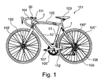
添付図面を参照すると、図1は、符号101によって示される自転車を概略的に示す。自転車101はフレーム102と、サドル103と、ハンドルバー104とを備える。さらに、自転車1は、フレーム102に関連付けられた第1の車輪105’と第2の車輪105’’とを備える。例えば、自転車自体の従来の進行方向に関して、第1の車輪105'は前輪であり、第2の車輪105’’は後輪である。
With reference to the accompanying drawings, FIG. 1 schematically illustrates the bicycle indicated by
自転車1は、チェーン112によって車輪105’または105’’の一方、例えば後輪105’’に機械的に結合されたペダル107を備えたペダル群106を備える。そのような機械的結合では、フリーホイール機構108と、場合によっては、シフター109とを設けることができる。
The bicycle 1 comprises a
フレーム102は、前輪105’を支持するフロントフォーク110’と、後輪105’’を支持するリアフォーク110’’とに接続される。本発明によるサスペンション1は、フレーム102とフロントフォーク110'との間、および/または、フレーム102とリアフォーク110’’との間に挿入される。サスペンション1が前方に位置する場合、これは特に、フレーム部分において回転可能に、ハンドルバー104に接続されたステアリングコラム111に接続されることができる。
The
図2を参照すると、図2は本発明によるサスペンション1の作動上の概要図を示す。 With reference to FIG. 2, FIG. 2 shows an operational schematic view of the suspension 1 according to the present invention.
サスペンション1は、例えばコイルばねまたは異なる種類の弾性体である弾性要素2を備える。さらに、サスペンション1は、弾性要素2が(この方法で懸架機能を得て)実質的に変形することのないように、または代わりに、これが実質的に遮断されるように、換言するとこれが実質的に剛性体として作用するように、後述するモードによって弾性要素2と相互作用することが可能な遮断/解放装置3を備える。 Suspension 1 includes, for example, a coil spring or an elastic element 2 which is a different type of elastic body. Further, the suspension 1 is provided so that the elastic element 2 is substantially not deformed (obtaining a suspension function in this manner), or instead, it is substantially blocked, in other words, this is substantially. It is provided with a blocking / releasing device 3 capable of interacting with the elastic element 2 in a mode described later so as to act as a rigid body.
このため、遮断/解放装置3は、作動流体5、例えば油を含む閉油圧回路4を備える。油圧回路4は、シリンダ10と、シリンダ10の内部で移動可能な、ステム7を備える油圧ピストン6であって、作動流体5に浸漬された、特に複動式ピストンである油圧ピストンとを備える、油圧シリンダ−ピストン群60を受け、これは油圧回路を2つの部分に分ける。
Therefore, the shutoff / release device 3 includes a closed hydraulic circuit 4 containing a working fluid 5, for example, oil. The hydraulic circuit 4 includes a
シリンダ−ピストンアセンブリ60は弾性要素2と並行に作動的に配置されている。具体的には、シリンダ10は弾性要素2の端部と作動的に接続され、一方ピストン6は、例えばそのステム7によって、弾性要素2の反対側の端部に作動的に接続される。そのような作動上の構成を得るために、例えば、ピストン6のステム7と弾性要素2の端部とがフロントフォーク100'またはリアフォーク110’’に接続されることが可能である。一方、ピストン6を摺動可能に受けるシリンダ10と弾性要素2の他端部は、フレーム102またはステアリングコラム111に接続されることが可能である。または、ピストン6のステム7と弾性要素2の端部とがフレーム102またはステアリングコラム111に接続されることが可能である。一方、ピストン6を摺動可能に受けるシリンダ10と弾性要素2の他端部は、フロントフォーク100'またはリアフォーク110’’に接続されることが可能である(viseversa)。ピストン6は、シリンダ10によって画成されたチャンバを第1のチャンバ10'と第2のチャンバ10とに分け、その容積は、ピストン6自体の動きの影響によって変化する。
The cylinder-
さらに、油圧回路4は、アクチュエータ9、例えば電気モータによって指令されるバルブ8を受ける。バルブ8は2つの構成をとることができ、それは開構成と閉構成とである。バルブ8が開構成にあるとき、作動流体5は油圧回路の内側を自由に摺動し、特にシリンダ10のチャンバ10’と10’’との間を自由に移動する。したがって、サスペンション1の作動上の状態における弾性要素2の振動の影響により、ピストン6はそれと共にシリンダ10の内側で振動し、また、ピストン6の振動は開放バルブ8を通る第1のチャンバ10’と第2のチャンバ10’’との間の流体移送によって整合される。第1のチャンバ10'と第2のチャンバ10’’との容積は逆に変化する。換言すると、一方のチャンバの容積が増加するにつれて、他方のチャンバの容積は減少する。
Further, the hydraulic circuit 4 receives an actuator 9, for example, a
代わりに、バルブ8が閉構成にあるとき、第1のチャンバ101’とバルブ8との間と、第2のチャンバ102’’とバルブ8との間の部分のそれぞれの、油圧回路の2つの部分は、互いに連通しない。したがって、第1のチャンバ10’と第2のチャンバ10’’との間の作動流体の交換は不可能である。したがって、作動流体5の実質的な非圧縮性により、ピストン6は、バルブ8が閉じられていたときの位置において、2つの回路部分内の作動流体により遮断されたままとなる。ピストン6は弾性要素2に作動的に接続され、弾性要素2は前記モードにより、ピストン6を滑動可能に受けるシリンダ10にも接続されるので、弾性要素2は遮断される。したがってサスペンションは実質的に剛性である。
Instead, when the
図3を参照すると、図3は、本発明の可能な実施形態によるサスペンション1の、図2における構成を実現する構造的アプローチを示す。サスペンション1は、例えば接続孔24によって、フレーム102またはステアリングコラム111に接続可能な主ハウジング11であって、前述の弾性要素2を実現するエラストマー体またはばね12に結合された主ハウジングを備えることができる。主ハウジング11は、シリンダ−ピストンアセンブリ60、特にシリンダ10を内側に受け、また、弾性要素2の端部へのシリンダ10の作動上の結合を予め実現するため、エラストマー体またはばね12の上端部にさらに固定される。
With reference to FIG. 3, FIG. 3 shows a structural approach to achieve the configuration of FIG. 2 for suspension 1 according to a possible embodiment of the present invention. The suspension 1 may include a
ピストン6のステム7は、シリンダ10と主ハウジング11とから出て、主ハウジング11への連結部が設けられる端部と反対側の端部によってエラストマー体またはばね12に接続される。このため、例えば、サスペンション1は、主ハウジング11に関して摺動可能であり、またピストン6のステム7と一体である補助チャンバ18であって、エラストマー体またはばね12を内側に受ける補助チャンバを備えることができる。弾性体またはばね12は、その弾性変形の影響により、補助チャンバ18が主ハウジング11へと向かう動きに対抗するようになっている。補助チャンバ18は、スリット17によって自転車のフォークに接続されることが可能である。この方法により、ピストン6と、弾性体12によって形成された弾性要素2との間の前述の作動上の連結部が実現される。この配置によれば、主ハウジング11上での補助チャンバ18の相対運動は、弾性体またはばね12の変形に変換され、また、チャンバ10の内側でのピストン6の動きに変換される。
The stem 7 of the piston 6 exits the
有利には、油圧回路4は、主ハウジング11の壁とシリンダ10の壁との間に形成された空間内に形成される。シリンダ10の壁は開口部19を示し、第1のチャンバ10'と第2のチャンバ10’’との間の連通を、適切に構成された油圧回路4によって可能にする。図3の例示的な実施形態によれば、バルブ8は、シリンダ10の壁と主ハウジング11の壁との間で、シリンダ10の上方で収容されることが可能である。
Advantageously, the hydraulic circuit 4 is formed in the space formed between the wall of the
好ましくは、バルブ8は、油圧回路4に含まれる作動流体と同一であり得る作動流体、または他の流体を内側で受ける油圧トランスミッション14によってバルブ8自体と連通する電気モータ15によって作動される。例えば、電気モータ15は、後退位置と伸長位置との間で並進運動することが可能なシャフト16を備えることができる。シャフト16の各位置は、電気モータ15のシャフト16によって、好ましくは膜20によって、加圧され、また動かされる油圧トランスミッション14内の作動流体によって作動される、バルブ8の位置と整合される。電気モータ15と膜20とは、油圧トランスミッション14に接続されたモータハウジング21内に収容されることができる。
Preferably, the
可能な実施形態によれば、油圧トランスミッション14は、例えば接続要素26によってバルブ8のシート部に接続された、好ましくはモータハウジング21によって形成された、例えば金属製の剛性チューブ25を備える。
According to a possible embodiment, the
可能な実施形態によれば、油圧回路4は、好ましくはまた主ハウジング11の壁とシリンダ10の壁との間の空間内に形成されたバランスチャンバ22と、好ましくは主ハウジング11の壁内に配置されたバルブ23とを備える。バランスチャンバの目的は、シリンダ10の内部に入るピストンによる、シリンダ10内部の全体的な容積増加のバランスをとることである。バルブ23は、シリンダ10内に存在する流体を取り除き、また充填することを可能にする。
According to a possible embodiment, the hydraulic circuit 4 is preferably also in the balance chamber 22 formed in the space between the wall of the
バルブ8の開閉、したがってサスペンションの遮断と解放とを手動または自動で指令することができる。第1のケースでは、例えばハンドルバー104上に位置決め可能な制御盤50(図1)が設けられ、それにより、サイクリストが例えばプッシュボタンを操作することにより、サスペンションを遮断または解除する指令をする。第2のケースでは、自転車および/またはサイクリスト上に配置されたセンサに接続された制御ユニット、たとえば自転車が走行している地形の高低差、ならびに/または自転車および/もしくはサイクリストの動きのレベルを示す測定値を供給することが可能な加速度計および/またはジャイロスコープが設けられる。それらに応じて、制御ユニットは自動的にバルブを開閉し、その結果サスペンションは解放または遮断される。更なる変形によれば、制御ユニットは、好ましくは無線で、GPSセンサ、電力計、カーディオ周波数計、ペダル推力ケイデンスセンサ等の更なるセンサに接続されることが可能である。
The opening and closing of the
記載された構成要素に確実に電気的供給を行うために、サスペンション1自体と、また、制御盤50にも接続されたバッテリーパック51が更に設けられる。好ましくは、バッテリーパック51および/または、バッテリーパック51をサスペンション1と制御盤50とに接続するワイヤ52は、好ましくは管状体を備えるフレームの内側に少なくとも部分的に収容される。
A suspension 1 itself and a
本発明によるサスペンションの実施形態に対し、当業者は、添付の特許請求の範囲から逸脱することなく、偶発的な特定の必要性を満たすために、追加、変更または他の作動的に等価なものとの要素の置換を取り入れることができる。 For embodiments of suspensions according to the invention, one of ordinary skill in the art will add, modify or otherwise operably equivalent to meet an accidental specific need without departing from the appended claims. You can incorporate the replacement of elements with.
Claims (10)
作動流体(5)を含む閉油圧回路(4)と、
シリンダ(10)、及び前記シリンダ内で摺動可能なピストン(6)を備え、前記油圧回路(4)内に挿入され、また作動的に前記弾性要素と並行に配置される、シリンダ−ピストンアセンブリ(60)と、
前記油圧回路(4)内に挿入されるアクチュエータ(9)によって指令され、前記ピストン(6)の前記シリンダ(10)の内側での動きを可能にするため、前記作動流体(5)が前記油圧回路を自由に流れるよう開構成に従って構成可能であり、かつ、前記作動流体(5)が前記油圧回路(4)内を流れることが防止され、また前記ピストン(6)が前記作動流体(5)によって遮断され続けるよう閉構成に従って構成可能な、バルブと、
シリンダ―ピストンアセンブリ(60)を内側で受ける主ハウジング(11)と、を備え、
油圧前記回路(4)は、前記主ハウジング(11)の壁と前記シリンダ(10)の壁との間に形成された空間内に形成される、自転車用サスペンション。 A suspension (1) for a bicycle (101) including an elastic element (2) and a blocking / releasing device (3) for the elastic element (2).
A closed hydraulic circuit (4) containing a working fluid (5) and
A cylinder-piston assembly comprising a cylinder (10) and a piston (6) slidable within the cylinder, inserted into the hydraulic circuit (4) and operatively placed parallel to the elastic element. (60) and
The working fluid (5) is driven by the hydraulic fluid (5) to allow the piston (6) to move inside the cylinder (10), commanded by an actuator (9) inserted into the hydraulic circuit (4). It can be configured according to an open configuration so that it can flow freely in the circuit, the working fluid (5) is prevented from flowing in the hydraulic circuit (4), and the piston (6) is the working fluid (5). With valves, which can be configured according to the closed configuration to remain shut off
Cylinder-with a main housing (11) that receives the piston assembly (60) inside.
The hydraulic circuit (4) is a bicycle suspension formed in a space formed between the wall of the main housing (11) and the wall of the cylinder (10).
前記バルブ(8)が開構成にあるとき、前記ピストン(6)の前記動きにより、前記作動流体(5)が前記第1チャンバ(10’)と前記第2チャンバ(10’’)との間を前記油圧回路(4)内の前記バルブ(8)を通って流れ、前記バルブ(8)が閉構成にある場合に、第1チャンバ(10’)と第2チャンバ(10’’)との間の前記作動流体の移送が阻止され、それによって前記ピストン(6)を遮断する、請求項1〜3のいずれか一項に記載のサスペンション(1)。 A suspension in which the piston (6) divides the cylinder (10) into a first chamber (10 ″) and a second chamber (10 ″) having a volume that changes depending on the position of the piston (6). (1)
When the valve (8) is in the open configuration, the movement of the piston (6) causes the working fluid (5) to move between the first chamber (10') and the second chamber (10 ″). Flows through the valve (8) in the hydraulic circuit (4), and when the valve (8) is in a closed configuration, the first chamber (10') and the second chamber (10 ″) are combined. The suspension (1) according to any one of claims 1 to 3, wherein the transfer of the working fluid between them is blocked, thereby shutting off the piston (6).
前記ピストン(6)が前記シリンダ(10)と前記主ハウジング(11)とから突出するステム(7)を備え、また、前記ピストン(6)が前記弾性要素(2)の前記第1の側とは反対の第2の側で前記弾性要素(2)に接続される、請求項1〜5のいずれか一項に記載のサスペンション(1)。 The main housing (11) is coupled to the elastic element (2) on the first side of the elastic element (2).
The piston (6) comprises a stem (7) protruding from the cylinder (10) and the main housing (11), and the piston (6) is associated with the first side of the elastic element (2). The suspension (1) according to any one of claims 1 to 5, which is connected to the elastic element (2) on the opposite second side.
前記補助チャンバ(18)は前記主ハウジング(11)に関して摺動可能であり、また前記補助チャンバ(18)は前記ピストン(6)のステム(7)と一体であり、
前記弾性要素(2)は、弾性的に変形することによって、前記主ハウジング(11)へと向かう前記補助チャンバ(18)の接近移動に対抗するよう位置決めされている、請求項1〜6のいずれか一項に記載のサスペンション(1)。 An auxiliary chamber (18) that receives the elastic element (2) on the inside is provided.
The auxiliary chamber (18) is slidable with respect to the main housing (11), and the auxiliary chamber (18) is integral with the stem (7) of the piston (6).
Any of claims 1 to 6, wherein the elastic element (2) is positioned to oppose the approaching movement of the auxiliary chamber (18) towards the main housing (11) by elastically deforming. The suspension (1) according to the first paragraph.
前記電気モータ(15)が、前記電気モータ(15)を前記油圧トランスミッション(14)から流体的に分離する膜(20)によって前記油圧トランスミッション(14)に作用する、直線移動可能なシャフト(16)を備える、請求項1〜8のいずれか一項に記載のサスペンション(1)。 The actuator (9) comprises an electric motor (15) that communicates with the valve (8) by a hydraulic transmission (14).
A linearly movable shaft (16) in which the electric motor (15) acts on the hydraulic transmission (14) by a film (20) that fluidly separates the electric motor (15) from the hydraulic transmission (14). The suspension (1) according to any one of claims 1 to 8.
Applications Claiming Priority (3)
| Application Number | Priority Date | Filing Date | Title |
|---|---|---|---|
| IT102016000106717 | 2016-10-24 | ||
| IT102016000106717A IT201600106717A1 (en) | 2016-10-24 | 2016-10-24 | Bicycle suspension |
| PCT/IB2017/055907 WO2018078464A1 (en) | 2016-10-24 | 2017-09-27 | Suspension for a bicycle |
Publications (2)
| Publication Number | Publication Date |
|---|---|
| JP2019534434A JP2019534434A (en) | 2019-11-28 |
| JP6899442B2 true JP6899442B2 (en) | 2021-07-07 |
Family
ID=58010274
Family Applications (1)
| Application Number | Title | Priority Date | Filing Date |
|---|---|---|---|
| JP2019542815A Active JP6899442B2 (en) | 2016-10-24 | 2017-09-27 | Bicycle suspension |
Country Status (6)
| Country | Link |
|---|---|
| US (1) | US10787222B2 (en) |
| EP (1) | EP3529139B1 (en) |
| JP (1) | JP6899442B2 (en) |
| CN (1) | CN109963777B (en) |
| IT (1) | IT201600106717A1 (en) |
| WO (1) | WO2018078464A1 (en) |
Families Citing this family (1)
| Publication number | Priority date | Publication date | Assignee | Title |
|---|---|---|---|---|
| DE102020100276A1 (en) * | 2020-01-09 | 2021-07-15 | Shimano Inc. | SUSPENSION CONTROL SYSTEM FOR THE SUSPENSION OF A HUMAN DRIVEN VEHICLE |
Family Cites Families (17)
| Publication number | Priority date | Publication date | Assignee | Title |
|---|---|---|---|---|
| US3470986A (en) * | 1967-06-29 | 1969-10-07 | Oldberg Mfg Co | Hydraulic shock absorber and flow control means therefor |
| JPS544472B2 (en) * | 1974-04-08 | 1979-03-07 | ||
| JPS5835488U (en) * | 1981-09-01 | 1983-03-08 | 株式会社昭和製作所 | Anti-nose dive mechanism for trailing front cushions for motorcycles, etc. |
| JPS5835489U (en) * | 1981-09-01 | 1983-03-08 | 株式会社昭和製作所 | Anti-nose dive mechanism in front cushions of motorcycles, etc. |
| ES8503803A1 (en) * | 1983-06-29 | 1985-03-01 | Boge Gmbh | Adjustable hydraulic damper apparatus |
| JPH0629191Y2 (en) * | 1985-04-23 | 1994-08-10 | スズキ株式会社 | Variable suspension device for motorcycles |
| JPH053786Y2 (en) * | 1988-03-15 | 1993-01-29 | ||
| US5275264A (en) * | 1992-09-25 | 1994-01-04 | Calzolari Isella | Setting shock absorber for cycles |
| ES2179705B2 (en) * | 1997-07-08 | 2003-06-16 | Mannesmann Sachs Ag | ADJUSTABLE VIBRATION SHOCK ABSORBER FOR MOTOR VEHICLES. |
| US7163223B2 (en) * | 2003-11-19 | 2007-01-16 | Sram Corporation | Lockout mechanism for a suspension system |
| GB2461892A (en) * | 2008-07-16 | 2010-01-20 | Univ Sheffield | A damper for a mountain bike |
| US8251376B2 (en) * | 2009-07-17 | 2012-08-28 | Shimano Inc. | Bicycle suspension having stroke and damper adjustment |
| TWM404816U (en) * | 2010-09-01 | 2011-06-01 | Kind Shock Hi Tech Co Ltd | Structure improvement for rear shock absorber |
| JP5715000B2 (en) * | 2011-07-28 | 2015-05-07 | 川崎重工業株式会社 | Control device and control method for saddle-ride type vehicle |
| CN103307189A (en) * | 2012-03-16 | 2013-09-18 | 刘政良 | New generation of energy-collecting damper |
| JP5961124B2 (en) * | 2012-04-27 | 2016-08-02 | Kyb株式会社 | Suspension device |
| US9481425B2 (en) * | 2013-11-18 | 2016-11-01 | Shimano Inc. | Bicycle suspension |
-
2016
- 2016-10-24 IT IT102016000106717A patent/IT201600106717A1/en unknown
-
2017
- 2017-09-27 WO PCT/IB2017/055907 patent/WO2018078464A1/en active Application Filing
- 2017-09-27 CN CN201780071801.9A patent/CN109963777B/en not_active Expired - Fee Related
- 2017-09-27 EP EP17785020.3A patent/EP3529139B1/en active Active
- 2017-09-27 US US16/344,037 patent/US10787222B2/en active Active
- 2017-09-27 JP JP2019542815A patent/JP6899442B2/en active Active
Also Published As
| Publication number | Publication date |
|---|---|
| JP2019534434A (en) | 2019-11-28 |
| US20190248441A1 (en) | 2019-08-15 |
| CN109963777B (en) | 2020-12-22 |
| WO2018078464A1 (en) | 2018-05-03 |
| US10787222B2 (en) | 2020-09-29 |
| IT201600106717A1 (en) | 2018-04-24 |
| CN109963777A (en) | 2019-07-02 |
| EP3529139A1 (en) | 2019-08-28 |
| EP3529139B1 (en) | 2021-09-01 |
Similar Documents
| Publication | Publication Date | Title |
|---|---|---|
| CN101665137B (en) | Bicycle suspension system | |
| US8955633B2 (en) | Two-wheeled motor vehicle | |
| US20090001684A1 (en) | Bicycle suspension assembly | |
| EP3985279A1 (en) | A multi-mode air shock | |
| US20120080279A1 (en) | Methods and apparatus for sag adjustment | |
| US9481425B2 (en) | Bicycle suspension | |
| SE531618C2 (en) | Electrically controlled pressurized damper | |
| US8740237B2 (en) | Bicycle with suspension | |
| US20080018035A1 (en) | Damper Unit For A Vehicle Suspension System | |
| US20230339567A1 (en) | Bicycle suspension components and electronic control devices | |
| JP6899442B2 (en) | Bicycle suspension | |
| JP2010159018A (en) | Suspension apparatus | |
| JP2015168394A (en) | Steering structure of saddle-riding type vehicle | |
| US20170356518A1 (en) | Spring unit | |
| WO2016047471A1 (en) | Front fork | |
| JP2014208510A (en) | Front fork | |
| WO2016024538A1 (en) | Front fork | |
| EP1905619B1 (en) | Vehicle suspension | |
| JP2012112423A (en) | Fluid pressure shock absorber | |
| JP6577896B2 (en) | Shock absorber | |
| JP5530263B2 (en) | Fluid pressure buffer | |
| JP2009121492A (en) | Front fork | |
| JP2005009541A (en) | Front fork of motorcycle, etc. | |
| CZ2014826A3 (en) | Central springing and damping unit of front cycle fork | |
| JP2011127744A (en) | Damper |
Legal Events
| Date | Code | Title | Description |
|---|---|---|---|
| RD01 | Notification of change of attorney |
Free format text: JAPANESE INTERMEDIATE CODE: A7426 Effective date: 20200727 |
|
| A621 | Written request for application examination |
Free format text: JAPANESE INTERMEDIATE CODE: A621 Effective date: 20200805 |
|
| A521 | Request for written amendment filed |
Free format text: JAPANESE INTERMEDIATE CODE: A821 Effective date: 20200727 |
|
| A977 | Report on retrieval |
Free format text: JAPANESE INTERMEDIATE CODE: A971007 Effective date: 20210521 |
|
| TRDD | Decision of grant or rejection written | ||
| A01 | Written decision to grant a patent or to grant a registration (utility model) |
Free format text: JAPANESE INTERMEDIATE CODE: A01 Effective date: 20210601 |
|
| A61 | First payment of annual fees (during grant procedure) |
Free format text: JAPANESE INTERMEDIATE CODE: A61 Effective date: 20210614 |
|
| R150 | Certificate of patent or registration of utility model |
Ref document number: 6899442 Country of ref document: JP Free format text: JAPANESE INTERMEDIATE CODE: R150 |