EP1905496B1 - Integrale Einwegfiltereinheit - Google Patents
Integrale Einwegfiltereinheit Download PDFInfo
- Publication number
- EP1905496B1 EP1905496B1 EP08150281A EP08150281A EP1905496B1 EP 1905496 B1 EP1905496 B1 EP 1905496B1 EP 08150281 A EP08150281 A EP 08150281A EP 08150281 A EP08150281 A EP 08150281A EP 1905496 B1 EP1905496 B1 EP 1905496B1
- Authority
- EP
- European Patent Office
- Prior art keywords
- filter
- filter unit
- plates
- disposable integral
- filtration
- Prior art date
- Legal status (The legal status is an assumption and is not a legal conclusion. Google has not performed a legal analysis and makes no representation as to the accuracy of the status listed.)
- Active
Links
- 238000001914 filtration Methods 0.000 claims abstract description 49
- 239000000463 material Substances 0.000 claims abstract description 43
- 239000012530 fluid Substances 0.000 claims abstract description 25
- -1 polypropylene Polymers 0.000 claims description 21
- 239000004743 Polypropylene Substances 0.000 claims description 15
- 229920001155 polypropylene Polymers 0.000 claims description 15
- 239000000706 filtrate Substances 0.000 claims description 12
- 238000003466 welding Methods 0.000 claims description 12
- 229920002678 cellulose Polymers 0.000 claims description 10
- 229920001169 thermoplastic Polymers 0.000 claims description 10
- 239000001913 cellulose Substances 0.000 claims description 9
- VYPSYNLAJGMNEJ-UHFFFAOYSA-N Silicium dioxide Chemical compound O=[Si]=O VYPSYNLAJGMNEJ-UHFFFAOYSA-N 0.000 claims description 8
- 239000012815 thermoplastic material Substances 0.000 claims description 8
- 239000004416 thermosoftening plastic Substances 0.000 claims description 8
- 239000011521 glass Substances 0.000 claims description 7
- 230000035699 permeability Effects 0.000 claims description 6
- 239000005909 Kieselgur Substances 0.000 claims description 5
- 229920002492 poly(sulfone) Polymers 0.000 claims description 4
- 239000012982 microporous membrane Substances 0.000 claims description 2
- 238000005352 clarification Methods 0.000 abstract description 8
- 239000002131 composite material Substances 0.000 abstract description 7
- 239000010410 layer Substances 0.000 description 17
- 238000000034 method Methods 0.000 description 16
- 239000000835 fiber Substances 0.000 description 13
- 239000012528 membrane Substances 0.000 description 12
- 238000010276 construction Methods 0.000 description 9
- 235000010980 cellulose Nutrition 0.000 description 8
- 238000004519 manufacturing process Methods 0.000 description 8
- 230000008901 benefit Effects 0.000 description 6
- 238000000465 moulding Methods 0.000 description 6
- 239000000654 additive Substances 0.000 description 5
- 229960000074 biopharmaceutical Drugs 0.000 description 5
- 230000015572 biosynthetic process Effects 0.000 description 5
- 230000014759 maintenance of location Effects 0.000 description 5
- 229920005989 resin Polymers 0.000 description 5
- 239000011347 resin Substances 0.000 description 5
- 239000011230 binding agent Substances 0.000 description 4
- 238000004140 cleaning Methods 0.000 description 4
- 229920000728 polyester Polymers 0.000 description 4
- 239000010935 stainless steel Substances 0.000 description 4
- 229910001220 stainless steel Inorganic materials 0.000 description 4
- 229920001187 thermosetting polymer Polymers 0.000 description 4
- 238000011144 upstream manufacturing Methods 0.000 description 4
- 238000010200 validation analysis Methods 0.000 description 4
- LYCAIKOWRPUZTN-UHFFFAOYSA-N Ethylene glycol Chemical compound OCCO LYCAIKOWRPUZTN-UHFFFAOYSA-N 0.000 description 3
- 239000002033 PVDF binder Substances 0.000 description 3
- 239000004695 Polyether sulfone Substances 0.000 description 3
- 239000004698 Polyethylene Substances 0.000 description 3
- 239000004793 Polystyrene Substances 0.000 description 3
- 229920001577 copolymer Polymers 0.000 description 3
- 229920001971 elastomer Polymers 0.000 description 3
- 150000002148 esters Chemical class 0.000 description 3
- 239000002657 fibrous material Substances 0.000 description 3
- 238000001746 injection moulding Methods 0.000 description 3
- 238000009434 installation Methods 0.000 description 3
- 239000004745 nonwoven fabric Substances 0.000 description 3
- 229920001778 nylon Polymers 0.000 description 3
- 229920000515 polycarbonate Polymers 0.000 description 3
- 239000004417 polycarbonate Substances 0.000 description 3
- 229920006393 polyether sulfone Polymers 0.000 description 3
- 229920000573 polyethylene Polymers 0.000 description 3
- 229920002223 polystyrene Polymers 0.000 description 3
- 229920001343 polytetrafluoroethylene Polymers 0.000 description 3
- 239000004810 polytetrafluoroethylene Substances 0.000 description 3
- 229920000915 polyvinyl chloride Polymers 0.000 description 3
- 229920002981 polyvinylidene fluoride Polymers 0.000 description 3
- 239000005060 rubber Substances 0.000 description 3
- 238000007789 sealing Methods 0.000 description 3
- 238000000926 separation method Methods 0.000 description 3
- OKTJSMMVPCPJKN-UHFFFAOYSA-N Carbon Chemical compound [C] OKTJSMMVPCPJKN-UHFFFAOYSA-N 0.000 description 2
- 239000004831 Hot glue Substances 0.000 description 2
- XEEYBQQBJWHFJM-UHFFFAOYSA-N Iron Chemical compound [Fe] XEEYBQQBJWHFJM-UHFFFAOYSA-N 0.000 description 2
- 239000004952 Polyamide Substances 0.000 description 2
- 229920001131 Pulp (paper) Polymers 0.000 description 2
- KKEYFWRCBNTPAC-UHFFFAOYSA-N Terephthalic acid Chemical compound OC(=O)C1=CC=C(C(O)=O)C=C1 KKEYFWRCBNTPAC-UHFFFAOYSA-N 0.000 description 2
- 238000010521 absorption reaction Methods 0.000 description 2
- 239000010425 asbestos Substances 0.000 description 2
- 125000002091 cationic group Chemical group 0.000 description 2
- 238000004891 communication Methods 0.000 description 2
- 238000005516 engineering process Methods 0.000 description 2
- 238000010348 incorporation Methods 0.000 description 2
- 239000002245 particle Substances 0.000 description 2
- 229920003023 plastic Polymers 0.000 description 2
- 239000004033 plastic Substances 0.000 description 2
- 229920002647 polyamide Polymers 0.000 description 2
- 229920000642 polymer Polymers 0.000 description 2
- 229920000098 polyolefin Polymers 0.000 description 2
- 239000004800 polyvinyl chloride Substances 0.000 description 2
- 239000011148 porous material Substances 0.000 description 2
- 238000011045 prefiltration Methods 0.000 description 2
- 239000000047 product Substances 0.000 description 2
- 239000004627 regenerated cellulose Substances 0.000 description 2
- 229910052895 riebeckite Inorganic materials 0.000 description 2
- 239000002002 slurry Substances 0.000 description 2
- 239000000243 solution Substances 0.000 description 2
- 239000000126 substance Substances 0.000 description 2
- XLYOFNOQVPJJNP-UHFFFAOYSA-N water Substances O XLYOFNOQVPJJNP-UHFFFAOYSA-N 0.000 description 2
- 229910001369 Brass Inorganic materials 0.000 description 1
- 244000025254 Cannabis sativa Species 0.000 description 1
- 235000012766 Cannabis sativa ssp. sativa var. sativa Nutrition 0.000 description 1
- 235000012765 Cannabis sativa ssp. sativa var. spontanea Nutrition 0.000 description 1
- 229920003043 Cellulose fiber Polymers 0.000 description 1
- PTHCMJGKKRQCBF-UHFFFAOYSA-N Cellulose, microcrystalline Chemical compound OC1C(O)C(OC)OC(CO)C1OC1C(O)C(O)C(OC)C(CO)O1 PTHCMJGKKRQCBF-UHFFFAOYSA-N 0.000 description 1
- RYGMFSIKBFXOCR-UHFFFAOYSA-N Copper Chemical compound [Cu] RYGMFSIKBFXOCR-UHFFFAOYSA-N 0.000 description 1
- 240000000491 Corchorus aestuans Species 0.000 description 1
- 235000011777 Corchorus aestuans Nutrition 0.000 description 1
- 235000010862 Corchorus capsularis Nutrition 0.000 description 1
- 229920000742 Cotton Polymers 0.000 description 1
- 239000004593 Epoxy Substances 0.000 description 1
- 229920000914 Metallic fiber Polymers 0.000 description 1
- 229920000168 Microcrystalline cellulose Polymers 0.000 description 1
- 239000004677 Nylon Substances 0.000 description 1
- 229920001328 Polyvinylidene chloride Polymers 0.000 description 1
- 229920000297 Rayon Polymers 0.000 description 1
- 239000004113 Sepiolite Substances 0.000 description 1
- RTAQQCXQSZGOHL-UHFFFAOYSA-N Titanium Chemical compound [Ti] RTAQQCXQSZGOHL-UHFFFAOYSA-N 0.000 description 1
- 239000004699 Ultra-high molecular weight polyethylene Substances 0.000 description 1
- 229920002494 Zein Polymers 0.000 description 1
- YKTSYUJCYHOUJP-UHFFFAOYSA-N [O--].[Al+3].[Al+3].[O-][Si]([O-])([O-])[O-] Chemical compound [O--].[Al+3].[Al+3].[O-][Si]([O-])([O-])[O-] YKTSYUJCYHOUJP-UHFFFAOYSA-N 0.000 description 1
- NIXOWILDQLNWCW-UHFFFAOYSA-N acrylic acid group Chemical group C(C=C)(=O)O NIXOWILDQLNWCW-UHFFFAOYSA-N 0.000 description 1
- 229920000122 acrylonitrile butadiene styrene Polymers 0.000 description 1
- 239000000853 adhesive Substances 0.000 description 1
- 238000004026 adhesive bonding Methods 0.000 description 1
- 230000001070 adhesive effect Effects 0.000 description 1
- 239000002671 adjuvant Substances 0.000 description 1
- 239000000956 alloy Substances 0.000 description 1
- 229910045601 alloy Inorganic materials 0.000 description 1
- 229910052782 aluminium Inorganic materials 0.000 description 1
- XAGFODPZIPBFFR-UHFFFAOYSA-N aluminium Chemical compound [Al] XAGFODPZIPBFFR-UHFFFAOYSA-N 0.000 description 1
- 125000000129 anionic group Chemical group 0.000 description 1
- 238000004166 bioassay Methods 0.000 description 1
- 230000033228 biological regulation Effects 0.000 description 1
- 239000010951 brass Substances 0.000 description 1
- 238000003490 calendering Methods 0.000 description 1
- 235000009120 camo Nutrition 0.000 description 1
- 239000005018 casein Substances 0.000 description 1
- BECPQYXYKAMYBN-UHFFFAOYSA-N casein, tech. Chemical compound NCCCCC(C(O)=O)N=C(O)C(CC(O)=O)N=C(O)C(CCC(O)=N)N=C(O)C(CC(C)C)N=C(O)C(CCC(O)=O)N=C(O)C(CC(O)=O)N=C(O)C(CCC(O)=O)N=C(O)C(C(C)O)N=C(O)C(CCC(O)=N)N=C(O)C(CCC(O)=N)N=C(O)C(CCC(O)=N)N=C(O)C(CCC(O)=O)N=C(O)C(CCC(O)=O)N=C(O)C(COP(O)(O)=O)N=C(O)C(CCC(O)=N)N=C(O)C(N)CC1=CC=CC=C1 BECPQYXYKAMYBN-UHFFFAOYSA-N 0.000 description 1
- 235000021240 caseins Nutrition 0.000 description 1
- 238000004113 cell culture Methods 0.000 description 1
- 229920002301 cellulose acetate Polymers 0.000 description 1
- 235000005607 chanvre indien Nutrition 0.000 description 1
- 239000003795 chemical substances by application Substances 0.000 description 1
- 229920000457 chlorinated polyvinyl chloride Polymers 0.000 description 1
- 230000003749 cleanliness Effects 0.000 description 1
- 230000000052 comparative effect Effects 0.000 description 1
- 230000006835 compression Effects 0.000 description 1
- 238000007906 compression Methods 0.000 description 1
- 238000007596 consolidation process Methods 0.000 description 1
- 238000007796 conventional method Methods 0.000 description 1
- 229910052802 copper Inorganic materials 0.000 description 1
- 239000010949 copper Substances 0.000 description 1
- 239000007799 cork Substances 0.000 description 1
- 230000001419 dependent effect Effects 0.000 description 1
- 230000008021 deposition Effects 0.000 description 1
- GUJOJGAPFQRJSV-UHFFFAOYSA-N dialuminum;dioxosilane;oxygen(2-);hydrate Chemical compound O.[O-2].[O-2].[O-2].[Al+3].[Al+3].O=[Si]=O.O=[Si]=O.O=[Si]=O.O=[Si]=O GUJOJGAPFQRJSV-UHFFFAOYSA-N 0.000 description 1
- CRPOUZQWHJYTMS-UHFFFAOYSA-N dialuminum;magnesium;disilicate Chemical compound [Mg+2].[Al+3].[Al+3].[O-][Si]([O-])([O-])[O-].[O-][Si]([O-])([O-])[O-] CRPOUZQWHJYTMS-UHFFFAOYSA-N 0.000 description 1
- NJLLQSBAHIKGKF-UHFFFAOYSA-N dipotassium dioxido(oxo)titanium Chemical compound [K+].[K+].[O-][Ti]([O-])=O NJLLQSBAHIKGKF-UHFFFAOYSA-N 0.000 description 1
- 230000000694 effects Effects 0.000 description 1
- 230000008030 elimination Effects 0.000 description 1
- 238000003379 elimination reaction Methods 0.000 description 1
- 125000003700 epoxy group Chemical group 0.000 description 1
- 230000001747 exhibiting effect Effects 0.000 description 1
- 229920002313 fluoropolymer Polymers 0.000 description 1
- 239000004811 fluoropolymer Substances 0.000 description 1
- 238000011194 good manufacturing practice Methods 0.000 description 1
- 238000010438 heat treatment Methods 0.000 description 1
- 239000011487 hemp Substances 0.000 description 1
- 229920001903 high density polyethylene Polymers 0.000 description 1
- 239000004700 high-density polyethylene Substances 0.000 description 1
- 239000005556 hormone Substances 0.000 description 1
- 229940088597 hormone Drugs 0.000 description 1
- 230000002209 hydrophobic effect Effects 0.000 description 1
- 239000012535 impurity Substances 0.000 description 1
- 229910052742 iron Inorganic materials 0.000 description 1
- 238000005304 joining Methods 0.000 description 1
- 230000033001 locomotion Effects 0.000 description 1
- 229920001684 low density polyethylene Polymers 0.000 description 1
- 239000004702 low-density polyethylene Substances 0.000 description 1
- 239000011159 matrix material Substances 0.000 description 1
- 230000008018 melting Effects 0.000 description 1
- 238000002844 melting Methods 0.000 description 1
- 229910052751 metal Inorganic materials 0.000 description 1
- 239000002184 metal Substances 0.000 description 1
- 125000005395 methacrylic acid group Chemical group 0.000 description 1
- 235000019813 microcrystalline cellulose Nutrition 0.000 description 1
- 239000008108 microcrystalline cellulose Substances 0.000 description 1
- 229940016286 microcrystalline cellulose Drugs 0.000 description 1
- 239000011490 mineral wool Substances 0.000 description 1
- 239000000203 mixture Substances 0.000 description 1
- 210000000050 mohair Anatomy 0.000 description 1
- 229910052901 montmorillonite Inorganic materials 0.000 description 1
- TWNQGVIAIRXVLR-UHFFFAOYSA-N oxo(oxoalumanyloxy)alumane Chemical compound O=[Al]O[Al]=O TWNQGVIAIRXVLR-UHFFFAOYSA-N 0.000 description 1
- 229910052625 palygorskite Inorganic materials 0.000 description 1
- 239000010451 perlite Substances 0.000 description 1
- 235000019362 perlite Nutrition 0.000 description 1
- 238000009428 plumbing Methods 0.000 description 1
- 238000005498 polishing Methods 0.000 description 1
- 229920002239 polyacrylonitrile Polymers 0.000 description 1
- 229920000647 polyepoxide Polymers 0.000 description 1
- 229920001296 polysiloxane Polymers 0.000 description 1
- 229920002635 polyurethane Polymers 0.000 description 1
- 239000004814 polyurethane Substances 0.000 description 1
- 239000005033 polyvinylidene chloride Substances 0.000 description 1
- 239000000843 powder Substances 0.000 description 1
- 230000001737 promoting effect Effects 0.000 description 1
- 238000000746 purification Methods 0.000 description 1
- 239000002510 pyrogen Substances 0.000 description 1
- 239000010453 quartz Substances 0.000 description 1
- 239000002994 raw material Substances 0.000 description 1
- 230000001105 regulatory effect Effects 0.000 description 1
- 229910052624 sepiolite Inorganic materials 0.000 description 1
- 235000019355 sepiolite Nutrition 0.000 description 1
- 239000000377 silicon dioxide Substances 0.000 description 1
- 229910052709 silver Inorganic materials 0.000 description 1
- 239000004332 silver Substances 0.000 description 1
- 239000002356 single layer Substances 0.000 description 1
- 239000007787 solid Substances 0.000 description 1
- 239000002904 solvent Substances 0.000 description 1
- 230000000087 stabilizing effect Effects 0.000 description 1
- 238000003786 synthesis reaction Methods 0.000 description 1
- 229920003051 synthetic elastomer Polymers 0.000 description 1
- 239000005061 synthetic rubber Substances 0.000 description 1
- 238000012360 testing method Methods 0.000 description 1
- 239000010936 titanium Substances 0.000 description 1
- 229910052719 titanium Inorganic materials 0.000 description 1
- 229920000785 ultra high molecular weight polyethylene Polymers 0.000 description 1
- 210000002268 wool Anatomy 0.000 description 1
- 239000005019 zein Substances 0.000 description 1
- 229940093612 zein Drugs 0.000 description 1
Images


Classifications
-
- B—PERFORMING OPERATIONS; TRANSPORTING
- B01—PHYSICAL OR CHEMICAL PROCESSES OR APPARATUS IN GENERAL
- B01D—SEPARATION
- B01D63/00—Apparatus in general for separation processes using semi-permeable membranes
- B01D63/08—Flat membrane modules
- B01D63/081—Manufacturing thereof
-
- B—PERFORMING OPERATIONS; TRANSPORTING
- B01—PHYSICAL OR CHEMICAL PROCESSES OR APPARATUS IN GENERAL
- B01D—SEPARATION
- B01D25/00—Filters formed by clamping together several filtering elements or parts of such elements
- B01D25/22—Cell-type filters
- B01D25/26—Cell-type stack filters
-
- B—PERFORMING OPERATIONS; TRANSPORTING
- B01—PHYSICAL OR CHEMICAL PROCESSES OR APPARATUS IN GENERAL
- B01D—SEPARATION
- B01D25/00—Filters formed by clamping together several filtering elements or parts of such elements
- B01D25/30—Feeding devices ; Discharge devices
-
- B—PERFORMING OPERATIONS; TRANSPORTING
- B01—PHYSICAL OR CHEMICAL PROCESSES OR APPARATUS IN GENERAL
- B01D—SEPARATION
- B01D39/00—Filtering material for liquid or gaseous fluids
- B01D39/14—Other self-supporting filtering material ; Other filtering material
- B01D39/16—Other self-supporting filtering material ; Other filtering material of organic material, e.g. synthetic fibres
- B01D39/18—Other self-supporting filtering material ; Other filtering material of organic material, e.g. synthetic fibres the material being cellulose or derivatives thereof
-
- B—PERFORMING OPERATIONS; TRANSPORTING
- B01—PHYSICAL OR CHEMICAL PROCESSES OR APPARATUS IN GENERAL
- B01D—SEPARATION
- B01D63/00—Apparatus in general for separation processes using semi-permeable membranes
- B01D63/08—Flat membrane modules
- B01D63/082—Flat membrane modules comprising a stack of flat membranes
- B01D63/0822—Plate-and-frame devices
-
- B—PERFORMING OPERATIONS; TRANSPORTING
- B01—PHYSICAL OR CHEMICAL PROCESSES OR APPARATUS IN GENERAL
- B01D—SEPARATION
- B01D2201/00—Details relating to filtering apparatus
- B01D2201/18—Filters characterised by the openings or pores
- B01D2201/182—Filters characterised by the openings or pores for depth filtration
-
- B—PERFORMING OPERATIONS; TRANSPORTING
- B01—PHYSICAL OR CHEMICAL PROCESSES OR APPARATUS IN GENERAL
- B01D—SEPARATION
- B01D2201/00—Details relating to filtering apparatus
- B01D2201/18—Filters characterised by the openings or pores
- B01D2201/188—Multiple filtering elements having filtering areas of different size
-
- B—PERFORMING OPERATIONS; TRANSPORTING
- B01—PHYSICAL OR CHEMICAL PROCESSES OR APPARATUS IN GENERAL
- B01D—SEPARATION
- B01D2313/00—Details relating to membrane modules or apparatus
- B01D2313/58—Parts of membrane modules specifically adapted for single use
Definitions
- the present invention is directed to disposable filter units, and in particular, to a disposable integral filter unit through which fluid flows in "parallel" through a plurality of deep gradient filter packets.
- the equipment used for the separation and purification of biopharmaceutical products must, for obvious reasons, meet stringent cleanliness requirements.
- the cleaning validation of new or re-commissioned equipment may require as much as 50 test-swabs of exposed surfaces and subsequent biological assays of such test swabs.
- the associated and reoccurring cost of a single cleaning validation may readily exceed multiple thousands of dollars.
- US-A-5922200 discloses a membrane filter unit for dead end filtration which is provided with a feed port, and a filtrate port.
- the unit has plural presealed elements and monolayer elements that are insert molded together such that an overmold which enters the stack structure for sealing represents the exterior parts of the filters and unit.
- US-A-4414172 discloses a filter unit with a plurality of filter elements which are sealed together by an overmold forming an integral filter element unit with a single frame structure.
- the filter element unit is clamped together with an inlet housing member and an outlet housing member by an overmold.
- the present invention provides a disposable integral filter unit as defined in claim 1.
- Preferred embodiments are defined in the dependent claims.
- the present invention provides a disposable integral filter unit 10 having an inlet 40 and an outlet 60, and comprising a plurality of filter plates 20n interposed between a pair of end plates 24,26.
- Each of the filter plates 20n comprises a thermoplastic framework 30 with a deep gradient filter packet 35 embedded therein.
- the filter plates and end plates are fused to form a substantially fixed, substantially water-tight, integral stack. Fluid entering the disposable integral filter unit 10 through said inlet 40 passes the deep gradient filter packet 35 of each filter plate 20n substantially contemporaneously prior to exiting said unit 10 through said outlet 60 ( cf. , "parallel" flow).
- the "parallel" flow path through the embedded deep gradient filter packets 35 promotes use of the filter unit 10 for the primary and/or secondary clarification of, for example, biopharmaceutical fluids.
- the disposable integral filter unit 10 is comparatively small and compact - desirable structural characteristics that promote easier installation and handling as compared with the typical, bulkier units currently in widespread use.
- the filter unit is configured such that no external housing is required for its use in filtration.
- the filter unit 10 can be installed directly within a fluid process stream. When spent, the filter unit is removed and replaced with a fresh one.
- the filter unit's polymeric framework 28 (a) is monolithic, (b) has an outer border, with interior-facing 214 and exterior-facing surfaces 217, circumscribing an internal area of said framework; and (c) provides a feed port 210, a filtrate port 212, and a filtration zone 216 within said exterior facing surface 214.
- a deep gradient filter packet 35 is embedded in the filtration zone 216.
- the packet 35 comprises strata or layers of filtration material stacked or otherwise deposited one against another to form a unitary pad-like composite. Depending on materials and manufacturing methodology, the composite is either self-supporting and/or unitized encapsulated within a porous outer envelope, sieve, or screen.
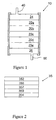
- Fig. 1 is a diagrammatic view of a disposable integral filter unit 10 according to an embodiment of the present invention, the filter unit 10 comprising a stack of filter plates 20n, into each of which is embedded a deep gradient filter packet.
- Fig. 2 is a diagrammatic view of a deep gradient filter packet 35, useful in the construction of a disposable integral filter unit.
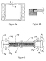
- Fig. 3a is a cross-sectional view of a single filter plate 20, useful in the construction of a disposable integral filter unit.
- Fig. 3b is a cross-sectional view of paired filter plates 20 I , 20 II , useful in the construction of a disposable integral filter unit.
- Fig. 3c is a top view of a filter plate 20, useful in the construction of a disposable integral filter unit.
- Fig. 3d is a top view of another filter plate 20, useful in the construction of a disposable integral filter unit.
- Fig. 4a is a top view of another filter plate 20 made in accordance with a two-step molding and embedding process.
- Fig. 4b is a cross-sectional view of the filter plate 20 illustrated in Fig. 4a , viewed along axis B-B.
- Fig. 5 is a cross-sectional view of paired filter plates 20 I , 20 II , useful in the construction of a disposable integral filter unit.
- Fig. 6 is a cross-sectional view of a disposable integral filter unit 10 according to a particular embodiment of the present invention, the filter unit 10 comprising a stack of filter plates 20n, into each of which is embedded a deep gradient filter packet 35.
- the present invention provides a disposable integral filter unit 10 having an inlet 40 and an outlet 60, and comprising a plurality of filter plates 20n interposed between a pair of end plates 24, 26.
- the disposable integral filter unit 10 is characterized particularly in that each of said filter plates 20n comprises a thermoplastic framework 28 and a deep gradient filter packet 35 embedded in said thermoplastic framework.
- the filter plates 20n and end plates 24, 26 form a substantially fixed integral stack, arranged and configured such that fluid entering the disposable integral filter unit 10 through the inlet 40 passes the deep gradient filter packet 35 of each filter plate 20n substantially contemporaneously (i.e., in "parallel") prior to exiting the unit 10 through its outlet 60.
- the disposable integral filter unit 10 - owing to its integral configuration - eliminates the need for a fixed outer housing, such as the comparatively expensive stainless steel housings currently in widespread use.
- the flow of fluid through the filter unit is substantially contained within its integral stack of plates -- a novel structural configuration that enables substantially water-tight construction.
- a fixed outer housing may still be employed.
- the disposable integral filter unit 10 can be implemented at a relatively low cost.
- the disposable integral filter unit 10 can be made as a "single use" item - i.e., "single use” in the sense that at the completion of the desired (or predetermined) fluid filtration operation, the filter unit 100 can either be disposed (e.g., as is sometimes required by law after filtering certain environmentally-regulated substances) or partially or completely revitalized or recycled (e.g., after filtering nonregulated substances).
- the disposable integral filter unit enables comparatively high volume fluid clarification (i.e., so-called "primary clarification") at a throughput comparable to that accomplished by large filter units, yet in a smaller, more compact footprint.
- This functionality is attributed in part to the device's, novel configuration and utilization of plural deep gradient filter packets, arranged within the unit 10's "parallel flow" path, such that each packet contributes to unit's overall available membrane area.
- Preferred embodiments of the inventive filter unit 10 are intended for high volume filtration of fluid containing particle sizes in the range of approximately 10 microns to 100 microns.
- Fig. 1 illustrates the filter unit 10 comprising filter plates 20a-n interposed in substantially normal relationship between end plates 24, 26, such configuration should not be construed as limiting.
- the stack of filter plates 20a-n can be interposed between the end plates 24, 26 in a substantially orthogonal relationship. This can be accomplished for example, by placing suitable inlets and outlets on or proximate the edge surfaces of each filter plate 20, and configuring the end plates as a manifold with corresponding flows paths that mate appropriately with said inlets and outlets of said plates 20a-n.
- Other configurations can, of course, be considered by those skilled in the art in view of the present description.
- the filter unit 10 can be designed such that all that is needed to create a suitable water tight flow path from the inlet to the outlet are permanently-combined filter plates 20a-n and end plates 24, 26, for certain application, for example, involving comparatively high fluid pressures and temperatures, a more robust structure may be desirable.
- the overmold 80 can, if desired, extend at least partially into the end plates 24 and 26 to clamp or otherwise fix those components.
- the overmold 80 can function, for example, to make the filter unit more robust ( cf ., water-tight) in the face of greater fluid pressures and/or temperatures.
- each of the filter plates 20n comprises a deep gradient filter packet 35 fixedly embedded within a polymeric, preferably plastic, more preferably thermoplastic framework 28.
- the polymeric framework 28 has a substantially flat, planar configuration, as does the deep gradient filter packet 35.
- Packet 35 is embedded within the polymeric framework 28 in substantially normal or co-planar orientation. The resultant filter plate thus assumes generally a slab-like configuration well suited for stacking adjacently one atop another.
- the polymeric framework 28 is specifically structured to define at least three non-overlapping zones, i.e., a filtration zone 216, an inlet port zone 210, and an outlet port zone.
- the deep gradient filter packet 35 is embedded and "framed" within the polymeric framework 28 specifically within its filtration zone 216.
- Figs. 3a, 3b, and 3c there is no particular limitation as to the shape, relative positions, and sizes of zones 216, 210, and 220. In respect of shape and size, those skilled in the art can select shapes and sizes appropriate to the particular filtration sought. Although only single specific outlet and inlet port zones 210, 212 are shown in Figs. 3a, 3b, and 3c , a plurality of said zones can be employed if desired. See e.g., Fig. 4a .
- the inlet and outlet zones are located opposite each other at far ends of the polymeric framework 28, with the filtration zone substantially centrally midway between the two ( see e.g., Figs. 3a and 3b ), this is not a requirement.
- Fig. 3c it is possible to construct an operable filter plate 20, wherein the inlet port zone 210 and outlet port zone 212 are proximate each other and surrounded substantially by the filtration zone 216.
- the structural extents of the polymeric framework 28 are bound by an outer wall having an outer wall surface 217 and an inner wall surface 214.
- the outer wall surfaces 217 of each component polymeric framework 28 form collectively the exterior side surfaces of the filter unit 10.
- the resultant composite outer wall of the filter unit 10 is sufficiently water tight, durable, and robust to enable filtration without use of an external housing but the invention requires a durable outer packet fixedly covering the exterior-facing surfaces of the filter plates and fixedly holding the end plates.
- the flow path through filter unit 10 is in large part determined by the structural configuration of the polymeric framework 28.
- the stack of filter plate 20n comprises several pairs of filter plate 20n. As shown in Fig. 3b , in each pair, two identical filter plates 20 I and 20 II are brought together and united "back to back" in register.
- fluid When fluid is introduced into said pair during the conduct of a filtration operation, fluid enters first into the combined inlet into the channel formed between the deep gradient filter packets. The fluid then passes through, and is filtered by, the deep gradient filter packet 35, then flows into the combined outlet port.
- the filter plate pair therein comprises two identical filter plates 20 I,II that each comprise a polymeric framework 28 I, II defining a inlet port zone 210 I, II , an outlet port zone 212 I, II , and a filtration zone 218 I, II substantially therebetween.
- Deep gradient filter packets 35 I, II are embedded in the respective filtration zones 216 I, II .
- the filter plates 20 I, II are united to form a feed channel 50 between the filter packets 35 I, II and filtrate channels 52 outside the filter packets 35 I, II .
- the combined inlet port zones 210 I, II provide openings enabling fluid access immediately into the feed channel 50.
- the combined outlet port zones 210 I, II provide openings that enable fluid access immediately out of the filtrate channels 52.
- the deep gradient filter packet 35 embedded within the polymeric framework 28 is characterized by its thick stratified arrangement of (preferably fiber-based) filtration material.
- the strata or layers of filtration materials are stacked one against another forming a composite pad-like structure that -- depending on selected manufacturing technique - is either "self-supporting" or is unitized encapsulated within a porous outer envelope, sieve, or screen.
- layers of cast membrane material or non-woven filter material may be used instead of the preferred fiber-based materials or in addition to such fiber-based materials as is known to one of skill in the art.
- each of the layers comprising the filter packet can be made of the same or different materials. However, each layer - in respect of functionalitybecomes progressively more retentive than the last, as one proceeds downstream through the packet.
- the upstream layer(s) provide a so-called "pre-filtration” function (i.e ., approximately 25 to approximately 1 micron retention); the middle layer(s) provide a so-called “primary filtration” function (i.e., approximately 1 micron to approximately 0.3 micron retention); and the downstream layer(s) provide a so-called "fluid polishing" function ( i.e ., approximately 0.3 microns to approximately 0.1 micron retention).
- Each layer or strata can be made of the same materials or different.
- Type of basic materials that can be employed for this purpose include polypropylene, polyester, glass, polyvinylchloride, polycarbonate polytetrafluoroethylene, polyvinylidene fluoride, cellulose, asbestos, nylon, polyethersulfone, and other polymeric (or non-polymeric) materials.
- Fibrous materials are generally preferred, because of their versatility, comparative ease of deposition, its strength imparting properties, internal surface to weight ratio, cost, and because fibers can be oriented in various positions and angles.
- Typical fibrous materials include glass and quartz, asbestos, potassium titanate, colloidal aluminum oxide, aluminum silicate, mineral wool, regenerated cellulose, microcrystalline cellulose, polystyrene, polyvinyl chloride, polyvinylidene chloride, polyacrylonitrile, polyethylene, polypropylene, rubber, polymers of terephthalic acid and ethylene glycol, polyamides, casein fibers, zein fibers, cellulose acetate, viscose rayon, hemp jute, linen, cotton, silk, wool, mohair, paper, metallic fibers such as iron, copper, aluminum, stainless steel, brass, silver, and titanium, and clays with acicular lath-like or needle-like particles, such as montmorillonite, sepiolite, palygorskite, and attapulgite
- the present invention is not limited to any particular morphology for the layers constituting the pre-filtration zone.
- the material can be formed as a pad of non-woven synthetic needle-felt.
- the polypropylene is preferably "virgin" fiber.
- the fibers are essentially free of binders, finishing agents, and other adjuvants which often are added to or coated on polypropylene fibers during or after its formation.
- "Virgin" polypropylene essentially contains no additives other than those inherent in the synthesis of the polypropylene.
- a filter pad or mat can be effected by various conventional techniques, of which mechanical, aerodynamic, or hydrodynamic web formation is used for natural and synthetic staple fibers and filaments and electrostatic formation for very fine denier fibers.
- Spunbonded materials can be formed from melt-spun filaments of thermoplastics, e.g., polyethylene, polypropylene, polyamide, or polyester, which are substantially consolidated by needling, a shrinkage treatment, or by the addition of a binder.
- Advantage may be realized by the spunbonded process in which the filament-forming polymers are in one operation melt-spun and cooled in air streams, drawn and then directly laid in pad or mat form.
- Spunbonded non-wovens are often desirable for use as filter material on account of their commercial and qualitative advantages over other non-wovens.
- one method of manufacture commences by first preparing a slurry comprising cellulose fibers, filter additives, and a polymeric thermoset binder.
- the slurry is vacuum felted and then cured at elevated temperature.
- the cationic resin when cured, forms a permanent, interconnected rigid structure.
- the result is a composite structure having a tortuous structure of flow channels and comprising the filter additives embedded in a cellulose matrix.
- the non-wovens used for manufacturing the filter are desirably used in the consolidated state.
- the materials can be consolidated in any conventional manner, for example by thermal bonding under pressure, in which the material is subjected to a calendering treatment, or by needling, or by thermal bonding using binders, such as hot-melt adhesives, for example in fiber or powder form, in which case the hot-melt adhesive must have a melting point which is lower than that of the fiber material of the web, or the pre-consolidation can be effected using a combination of the aforementioned measures.
- filter aids i.e ., so-called "filter aids”.
- filter aids can be incorporated by use of suitable anionic, cationic, or nonionic binding resins.
- suitable anionic, cationic, or nonionic binding resins include, but are not limited to, acid-washed diatomaceous earth, perlite, fumed precipitated silica (for hydrophobic absorption); and activated carbon (for absorption certain hormones and pyrogens).
- Membranes such as cast or non-woven or stretched microporous membranes are useful as one or more of the final layers (0.45 or 0.2 micron pore size) providing higher retention of impurities as the material flows through the deep bed packet 35.
- Suitable materials for such membranes include but are not limited to celluloses, including regenerated cellulose and mixed esters of cellulose, polyvinylidene fluoride, polysulfone, polyethersulfone, polyarylsulfone, nylons, polyester, polycarbonate, polystyrene, PTFE resin, polypropylene, polyethylene and the like.
- RW membrane mixed ester cellulosic product
- PVDF membrane known as Durapore ® membrane
- PES membrane known as the Millipore Express ® membrane
- the incorporation of the deep gradient filter packet 35 into a polymeric framework 28 is preferably accomplished by injection molding. While conventional injection molding methodologies can be used for certain applications, the well-documented post-formation, pre-curing structural instabilities of many thermoplastic materials (e.g., shrinkage) can have an unintended influence on the structural integrity of the incorporated filtration material. For example, if the density gradient filter packet 35 sought to be incorporated is of a type engineered to enable high resolution separations (such as common in biopharmaceutical fluid separations), even a slight structural permutation of the surrounding polymeric framework 28, even if short lived and temporary, can compromise unacceptably the structural integrity of said filter packet 35. Certain thermoplastic raw material, as the case also with large bulky frame formats, can produce such severe structural contortions during curing that the structural and functional integrity of even robust density gradient filter packets would not be immune from such influences.
- thermoplastic raw material as the case also with large bulky frame formats, can produce such severe structural contortions during curing that the structural and functional integrity of even
- the polymeric framework 28 affords greater functionality, if designed sufficiently thick to withstand the force of internal pressure during operation of the completed device. However, the more thickly molded the frame, the greater the inclination for it to shrink. Concerns over distortion and shrinkage can also limit material selection.
- a two-step molding process wherein a substantial first portion of the frame is made and allowed to shrink to its natural state, with the remaining lesser portion molded during or contemporaneously with the embedding of the deep gradient filter packet. More particularly, a two-step molding process can comprise the steps of: (a) forming a first portion of said polymeric framework from a thermoplastic polymer, said outer first portion providing at least said filtration zone; (b) placing said deep gradient filter packet in said filtration zone; and (c) forming a second portion of said polymeric framework from said thermoplastic polymer, said second portion completing said polymeric framework and embedding said deep gradient filter packet in place.
- the advantages of the two-step molding process flows principally from the stabilizing, bracing effect provided by the first formed portion.
- the thermoplastic material of the second formed portion cools (or otherwise hardens)
- shrinkage or warping will likely occur, but will be much more limited in view of the spatial constraints imposed by the dimensionally-stabilized first portion and its comparatively smaller mass.
- the density gradient filter packet 35 thus becomes embedded robustly within the polymeric framework, under conditions that are comparatively gentle and thus less likely to compromise its structural and functional integrity.
- thermoplastic materials have been highlighted in the above example for use in forming the polymeric framework 28, other materials such as thermosets and rubbers may also be used as part or all of the framework if desired or required by the application and as are described below.
- the deep gradient filter packet 35 comprises a plurality of adjacent filter layers 355, 357, and 359 interposed between screens 352 and 354, the retention of each said filter layer being greater than ( i.e ., more selective) than the layer preceding it.
- the deep gradient filter packet is composed as follows: Component Material Thickness (mm) Permeability (LMH/kPa) Screen 352 Polypropylene extruded diagonal weave screen 0.56 (0,022 in.) - Filter Layer 355 (DE50) Wet-laid pad comprising cellulose wood pulp and diatomaceous earth 3.3 (0.13 in.) 261.07 (1800 (LMH/psi)) Filter Layer 357 (DE75) Wet-laid pad comprising cellulose wood pulp and diatomaceous earth 3.3 (0.13 in.) 43.51 (300 (LMH/psi)) Membrane 351 (RW01) Mixed esters of cellulose, microporous membrane, nominal 0.1 micron pore size 0.23 (0.009 in.) 29 (200 (LMH/psi)) Screen 354 Polypropylene extruded diagonal weave screen 0.56 (0.022 in.) -
- each of the aforementioned pre-bonded filter plate pairs are sequentially brought together, positioned into appropriate register, then permanently bonded together, forming water-tight seals.
- the end caps 24 and 26 are positioned on the downstream and upstream sides of the stack, respectively, and permanently bonded in a manner that forms water-tight seals.
- the permanent bonds can be accomplished by use of, for example, mechanical couplers, adhesives, thermal sealing, and the like.
- thermoplastic materials In respect of thermal sealing procedures -- particularly for the assembly of embodiments of the type illustrated in Fig. 4a -- vibration welding provides particularly good results with thermoplastic materials.
- Vibration welding and the several variants thereof are well known technologies.
- the components to be fused are at certain predesignated points of contact made to vibrate at frequencies, for example, in excess of 20,000 cycles per second (i.e., 20Hz). Intense heat is generated in a matter of microseconds to melt the thermoplastic material and weld the layers at said points of contact.
- Vibration welding is preferred over other thermal welding process as the generated heat is comparatively narrowly localized and is quickly dissipated, thus eliminating the necessity of elaborate and/or costly heat removal systems.
- Vibration welding is the preferred method for thermally bonding rectangular, "un-jacketed" configurations of the inventive filter unit.
- This configuration consists essentially of several rectangular filter plates (e.g., of the type shown in Fig. 4a ) interposed integrally between a pair of end plates.
- the integral rectangular filter plates are constructed and bonded between the end plates to eliminate any need for, desire for, or advantage of using an outer jacket.
- Thermoplastic materials exhibiting high dimensional stability e.g., glass filled polypropylene or polysulfone
- glass filled polypropylene or polysulfone are the preferred materials for such embodiment.
- the generally higher costs of using glass-filled thermoplastic materials is offset by the lower costs associated with vibration welding, combined with the elimination of a jacket over-molding step.
- the resultant "un-jacketed" filter unit can be used for filtration of industrial volumes of fluids in either a vertical or horizontal position with comparatively minimal housing and installation requirements.
- the use of common compression plates, inlets, outlets, and associated flow controls would likely be all that is structurally needed in respect of installation.
- Three variants of vibration welding useful for fusing all or some of the components envisioned herein are: Angular welding (using frequencies up to 100 Hz, and angles up to 15 degrees); linear welding (using frequencies of 100 to 300 Hz and amplitudes of 0.5 to 2.5 mm); and biaxial oscillating motions (using frequencies of 80 to 250 Hz, and amplitudes up to 0.7 mm).
- the end caps 24 and 26 seal off the upstream and downstream ends of the stack of filter plates. They are generally made of the same polymeric materials as the polymeric framework of the filter plates, and can be molded or cast as a singly unitary monolithic piece or can be a conglomerate of assembled pieces. Preferably, the end caps 24 and 26 will have integrally formed thereon the filter unit's inlet 40 and outlet 60, respectively.
- Port plugs can also be used, as appropriate, to plug or otherwise block the upstream and downstream ends of the feed and filtrate lines running orthogonally through the stack of the filter plates 20n. See e.g., Fig. 6 .
- the port plugs can be formed integrally as part of the end caps 24 and 26, or can exist as independent components that can later in construction be positioned to abut against the endplates 24 and 26, and thereby -- like a cork -- plug forcibly into the opening of the feed and filtrate lines.
- the materials and structural assemblage of the port plugs, end caps 24, 26, and the polymeric framework 28 should be selected with an eye towards promoting the disposability and the integral character sought by the invention.
- the structural and/or rigid filter unit components - essentially all components, excepting the filter materials -- should generally be formed monolithically (i.e., as a single, homogenous, unitary, unassembled piece) from polymeric material, for example, by well-known injection molding processes.
- polystyrenes examples include, but are not limited to, polycarbonates, polyesters, nylons, PTFE resins and other fluoropolymers, acrylic and methacrylic resins and copolymers, polysulphones, polyethersulphones, polyaryl-sulphones, polystyrenes, polyvinyl chlorides, chlorinated polyvinyl chlorides, ABS and its alloys and blends, polyolefins (e.g., low density polyethylene, high density polyethylene, and ultrahigh molecular weight polyethylene and copolymers thereof), polypropylene and copolymers thereof, and metallocene generated polyolefins as well as thermosets, rubbers and other curable polymeric materials such as polyurethanes, epoxies, synthetic rubbers such as silicones and the like.
- polycarbonates polyesters, nylons, PTFE resins and other fluoropolymers, acrylic and methacrylic resins and copolymers
- Fig. 6 illustrates an embodiment of a disposable integral filter unit 10 according to the present invention.
- the disposable integral filter unit 10 comprises a plurality of cylindrical filter plates 20a-n interposed between end plates 24 and 26.
- End plate 24 having a shell-like configuration
- end plate 26 having a solid configuration
- An outer jacket 80 over-molded onto the stack of plates, "hooks" onto the outer rims of each of end plates 24 and 26.
- the filter plates 20a-n are configured and arranged to provide feed channels " x " and filtrate channels " y " leading to and away from each of the deep gradient filter packet 35 embedded within each plate.
- the feed channels "x" are in “communication” immediately with the core feed line FD passing orthogonally through plates; flow at the furthest end of the core feed line FD being obstructed by port plug 84.
- the filtrate channels are in "communication” immediately with the core filtrate line FT passing orthogonally through the plates; backflow into the upper regions of the core filtrate line FT being obstructed by port plug 82.
- Screen material 65 - such as an "open-mesh” polypropylene screen of approximately 5.08 mm (0.2 inch) to approximately 10.16 mm (.040 inch) thickness -- is used in both the feed channels " x " and filtrate channels "y".
Claims (11)
- Eine integrale Einwegfiltereinheit (10) mit einem Einlass (40) und einem Auslass (60), sowie mit einer Vielzahl von Filterplatten (20n), die zwischen einem Paar Endplatten (24,26) eingefügt sind,
wobei jede der Filterplatten (20n) seinen eigenen Polymerrahmen (28) mit einer nach außen gerichteten Oberfläche (217) und einem in den Polymerrahmen (28) eingebetteten Tiefenverlauffilterpaket (35) besitzt,
wobei die Filterplatten (20n) und Endplatten (24,26) einen im Wesentlichen befestigten integralen Stapel bilden, derart, dass in die integrale Einwegfiltereinheit (10) durch den Einlass (40) eintretendes Fluid das Tiefenverlauffilterpaket (35) jeder Filterplatte (20n) im Wesentlichen gleichzeitig passiert, bevor es die Einheit durch den Auslass (60) verlässt, und
wobei die Filtereinheit (10) ferner einen beständigen Außenmantel (80) aufweist, die die nach außen gerichteten Oberflächen (217) der Filterplatten (20n) befestigt abdeckt und die Endplatten (24,26) festhält. - Die integrale Einwegfiltereinheit gemäß Anspruch 1, wobei das Tiefenverlauffilterpaket (35) eine Vielzahl von Schichten aus Filtermaterial aufweist, wobei die Permeabilität der ersten Filterschicht größer ist als die Permeabilität der letzten Filterschicht.
- Die integrale Einwegfiltereinheit gemäß Anspruch 2, wobei das Tiefenverlauffilterpaket (35) drei Schichten Filtermaterial aufweist, und wobei:(a) die erste Schicht aus Filtermaterial aus Cellulose und kieselalgenhaltiger Erde aufgebaut ist und eine Permeabilität von etwa 261,07 LMH/kPa (1800 LMH/psi) besitzt,(b) die zweite Schicht aus Filtermaterial aus Cellulose und kieselalgenhaltiger Erde aufgebaut ist und eine Permeabilität von etwa 43,51 LMH/kPa (300 LMH/psi) besitzt, und(c) die dritte Schicht aus Filtermaterial eine mikroporöse Membran ist und eine Permeabilität von etwa 29 LMH/kPa (200 LMH/psi) besitzt.
- Die integrale Einwegfiltereinheit gemäß einem der Ansprüche 1 bis 3, wobei der Polymerrahmen (28):(a) monolithisch ist,(b) eine Wand besitzt, mit einer nach innen gerichteten Oberfläche (214) und der nach außen gerichteten Oberfläche (217), welche einen Innenbereich des Rahmens (28) begrenzt, und(c) einen Zuführanschluss (210), einen Filtratanschluss (212) und eine Filtrationszone (216) in der nach außen gerichteten Oberfläche (217) vorsieht.
- Die integrale Einwegfiltereinheit gemäß einem der Ansprüche 1 bis 3, wobei der Polymerrahmen (28) monolithisch, im Wesentlichen rechteckig und mit Anschlüssen versehen ist.
- Die integrale Einwegfiltereinheit gemäß einem der Ansprüche 1 bis 5, wobei die Vielzahl von Filterplatten (20n) aneinandergrenzend verschmolzen sind.
- Die integrale Einwegfiltereinheit gemäß Anspruch 6, wobei die aneinandergrenzend verschmolzenen Filterplatten durch Vibrationsschweißen angrenzend verschmolzen sind.
- Die integrale Einwegfiltereinheit gemäß einem der Ansprüche 1 bis 7, wobei der Polymerrahmen aus thermoplastischem Material gebildet ist.
- Die integrale Einwegfiltereinheit gemäß Anspruch 8, wobei
der Polymerrahmen aus einem mit Glas gefüllten thermoplastischen Material, vorzugsweise aus mit Glas gefülltem Polypropylen oder mit Glas gefülltem Polysulfon hergestellt ist. - Die integrale Einwegfiltereinheit gemäß Anspruch 8 oder 9, wobei die Filterplatten (20n) und Endplatten (24,26) aus thermoplastischem Material gebildet sind und durch Vibrationsschweißen miteinander verschweißt sind, um den im Wesentlichen feststehenden integralen Stapel zu bilden, wobei der im Wesentlichen feststehende integrale Stapel von dem Einlass (40) zu dem Auslass (60) im Wesentlichen wasserdicht ist.
- Die integrale Einwegfiltereinheit gemäß einem der Ansprüche 1 bis 10, wobei der Außenmantel (80) so gebildet ist, dass er an Außenrändern der Endplatten (24,26) eingehakt ist.
Applications Claiming Priority (3)
| Application Number | Priority Date | Filing Date | Title |
|---|---|---|---|
| US10/871,694 US20050279694A1 (en) | 2004-06-17 | 2004-06-17 | Disposable integral filter unit |
| US14884605P | 2005-06-09 | 2005-06-09 | |
| EP05105183A EP1609517B1 (de) | 2004-06-17 | 2005-06-14 | Integrale Einwegfiltereinheit |
Related Parent Applications (2)
| Application Number | Title | Priority Date | Filing Date |
|---|---|---|---|
| EP05105183.7 Division | 2005-06-14 | ||
| EP05105183A Division EP1609517B1 (de) | 2004-06-17 | 2005-06-14 | Integrale Einwegfiltereinheit |
Publications (2)
| Publication Number | Publication Date |
|---|---|
| EP1905496A1 EP1905496A1 (de) | 2008-04-02 |
| EP1905496B1 true EP1905496B1 (de) | 2011-12-28 |
Family
ID=35479497
Family Applications (2)
| Application Number | Title | Priority Date | Filing Date |
|---|---|---|---|
| EP08157208.3A Active EP1967244B1 (de) | 2004-06-17 | 2005-06-14 | Einweg-Integralfiltereinheit |
| EP08150281A Active EP1905496B1 (de) | 2004-06-17 | 2005-06-14 | Integrale Einwegfiltereinheit |
Family Applications Before (1)
| Application Number | Title | Priority Date | Filing Date |
|---|---|---|---|
| EP08157208.3A Active EP1967244B1 (de) | 2004-06-17 | 2005-06-14 | Einweg-Integralfiltereinheit |
Country Status (6)
| Country | Link |
|---|---|
| US (1) | US20050279695A1 (de) |
| EP (2) | EP1967244B1 (de) |
| JP (2) | JP2006000848A (de) |
| AT (2) | ATE427152T1 (de) |
| DE (1) | DE602005013606D1 (de) |
| ES (3) | ES2322370T3 (de) |
Families Citing this family (21)
| Publication number | Priority date | Publication date | Assignee | Title |
|---|---|---|---|---|
| US20070017879A1 (en) * | 1998-12-03 | 2007-01-25 | Stephen Proulx | Filtration cartridge and process for filtering a slurry |
| US20050279694A1 (en) * | 2004-06-17 | 2005-12-22 | Gregory Straeffer | Disposable integral filter unit |
| EP1888200A1 (de) * | 2005-05-08 | 2008-02-20 | 3M Innovative Properties Company | Filterpatrone und herstellungsverfahren dafür |
| US20080257814A1 (en) * | 2007-04-23 | 2008-10-23 | Millipore Corporation | Filtration Cartridge |
| CN103394291B (zh) | 2007-05-17 | 2016-12-07 | Emd密理博公司 | 膜层压板 |
| JP2011507686A (ja) * | 2007-12-21 | 2011-03-10 | スリーエム イノベイティブ プロパティズ カンパニー | フィルター装置 |
| CN102245277B (zh) * | 2008-11-04 | 2014-07-23 | 3M创新有限公司 | 流体互连器 |
| CN102665641A (zh) * | 2009-12-17 | 2012-09-12 | 3M创新有限公司 | 用于生物制药应用的塑料压力容器及其方法 |
| JP6018505B2 (ja) | 2010-01-11 | 2016-11-02 | ジーイー・ヘルスケア・バイオサイエンス・アクチボラグ | 分離又は反応システムの無菌接続 |
| US8708163B2 (en) * | 2010-12-15 | 2014-04-29 | Johns Manville | Spunbond polyester fiber webs |
| EP2788106A4 (de) * | 2011-12-09 | 2015-03-11 | Emd Millipore Corp | Entwurf einer tff-vorrichtung mit hoher viskosität |
| EP2854999B1 (de) * | 2012-05-30 | 2020-04-01 | GE Healthcare Bio-Sciences AB | Filtrierungskassette und stapel aus filtrierungskassetten |
| JP2015520026A (ja) * | 2012-06-06 | 2015-07-16 | イー・エム・デイー・ミリポア・コーポレイシヨン | 溶媒抽出法で処理される低有機抽出物デプスフィルター媒体 |
| US8580560B1 (en) | 2012-12-14 | 2013-11-12 | Scientific Plastic Products, Inc. | Cap with filter and transfer apparatus |
| KR20160013173A (ko) | 2013-08-30 | 2016-02-03 | 이엠디 밀리포어 코포레이션 | 추출가능물이 적은 대용량 복합 심층 필터 매질 |
| DE102017116923A1 (de) * | 2017-07-26 | 2019-01-31 | Sartorius Stedim Biotech Gmbh | Einweg-Filtercapsule für eine Filtrationsvorrichtung |
| US11400393B2 (en) * | 2017-11-29 | 2022-08-02 | Maagan Filtration Aca Ltd. | Filtration system |
| CA3130894A1 (en) * | 2019-02-20 | 2020-08-27 | Emd Millipore Corporation | Device for bind and elute chromatography using membranes, and method of manufacture |
| SG11202106921TA (en) * | 2019-03-28 | 2021-07-29 | Emd Millipore Corp | Head space for depth filters and method of using same |
| KR20230148409A (ko) * | 2020-11-17 | 2023-10-24 | 이엠디 밀리포어 코포레이션 | 바이오프로세싱을 위한 여과 장치 |
| KR102646824B1 (ko) * | 2023-12-07 | 2024-03-11 | 정필성 | 친환경 필터 고정프레임 |
Family Cites Families (40)
| Publication number | Priority date | Publication date | Assignee | Title |
|---|---|---|---|---|
| NL19860C (de) * | 1952-09-23 | |||
| US3241678A (en) * | 1961-12-13 | 1966-03-22 | American Felt Co | Fibrous structures |
| US3353682A (en) * | 1966-02-28 | 1967-11-21 | Pall Corp | Fluid-permeable fibrous multilayer materials and process of making the same |
| GB1279856A (en) * | 1968-08-23 | 1972-06-28 | Gen Electric | Improvements in starting control scheme for rectifier-inverter systems |
| US3647084A (en) * | 1969-10-17 | 1972-03-07 | William W Nugent & Co Inc | Filter |
| FR2207740B1 (de) * | 1972-11-24 | 1976-04-30 | Rhone Poulenc Ind | |
| US3976576A (en) * | 1974-04-01 | 1976-08-24 | The University Of Utah | Dialyzer cartridge |
| US4016081A (en) * | 1974-04-22 | 1977-04-05 | Baxter Laboratories, Inc. | Staged membrane diffusion device and membrane support |
| JPS5854847B2 (ja) * | 1976-05-21 | 1983-12-07 | 宏之 金井 | 濾過筒 |
| GB2003053B (en) * | 1977-08-19 | 1982-07-14 | Kuraray Co | Plate type fluid treatment apparatus |
| US4228015A (en) * | 1979-01-29 | 1980-10-14 | Baxter Travenol Laboratories, Inc. | Plasma treatment apparatus |
| US4645567A (en) * | 1980-02-04 | 1987-02-24 | Cuno, Inc. | Filter media and method of making same |
| US4511473A (en) * | 1982-02-09 | 1985-04-16 | Amf Incorporated | Fibrous media containing millimicron-sized particulates |
| US4488969A (en) * | 1982-02-09 | 1984-12-18 | Amf Incorporated | Fibrous media containing millimicron-sized particulates |
| US4414172A (en) * | 1982-05-21 | 1983-11-08 | Filtertek, Inc. | Process and apparatus for sealing a plurality of filter elements |
| DE3271426D1 (en) * | 1982-10-22 | 1986-07-03 | Gessner & Co Gmbh | Multilayer filter material, process for making it and its use |
| US4606824A (en) * | 1984-10-26 | 1986-08-19 | Chaokang Chu | Modified cellulose separation matrix |
| GB2201904B (en) * | 1987-02-14 | 1990-12-19 | Domnick Hunter Filters Ltd | Device for liquid chromatography or immobilised enzyme reaction |
| DE3900934A1 (de) * | 1989-01-14 | 1990-07-19 | Seitz Enzinger Noll Masch | Filtervorrichtung |
| DE3940264A1 (de) * | 1989-12-06 | 1991-06-13 | Hoechst Ag | Zwei- oder mehrschichtiges vliesstoffmaterial, insbesondere mit langzeitfiltereigenschaften, sowie verfahren zu seiner herstellung |
| DE4028379A1 (de) * | 1990-09-07 | 1992-03-12 | Seitz Filter Werke | Filtrationsmodul und filtrationsvorrichtung zur trennung und filtration von fluiden im crossflow-verfahren, sowie verfahren zur herstellung des filtrationsmoduls |
| GB9106481D0 (en) * | 1991-03-27 | 1991-05-15 | Pall Corp | Filters and filter units |
| SE503277C2 (sv) * | 1993-07-20 | 1996-05-13 | Alfa Laval Brewery Syst Ab | Filter avsett för tvärströmsfiltrering |
| DE9320208U1 (de) * | 1993-12-31 | 1994-03-31 | Kalthoff Luftfilter Und Filter | Mehrschichtiges Filtermaterial |
| US5490926A (en) * | 1994-10-31 | 1996-02-13 | W.R. Grace & Co.-Conn. | Spiral-wound filtration cartridge with longitudinal bypass feature |
| US5472600A (en) * | 1995-02-01 | 1995-12-05 | Minnesota Mining And Manufacturing Company | Gradient density filter |
| US5824217A (en) * | 1996-03-27 | 1998-10-20 | Millipore Corporation | Membrane filtration apparatus |
| JP3322595B2 (ja) * | 1996-03-28 | 2002-09-09 | テルモ株式会社 | フィルター装置および生体微細組織の分離・回収方法 |
| US5766472A (en) * | 1996-10-29 | 1998-06-16 | Illinois Tool Works Inc. | Method and apparatus for a filter assembly |
| US5965019A (en) * | 1996-11-26 | 1999-10-12 | Cuno Incorporated | Encapsulated lenticular filter cartridge |
| US5853445A (en) * | 1997-08-06 | 1998-12-29 | Dana Corporation | Interlocking dual filter |
| DE19837257A1 (de) * | 1998-08-17 | 2000-02-24 | Seitz Filter Werke | Filtermodul |
| US6712966B1 (en) * | 1999-02-04 | 2004-03-30 | Cuno Incorporated | Graded particle-size retention filter medium for cell-type filter unit |
| DE69907726T2 (de) * | 1998-12-03 | 2004-02-26 | Mykrolis Corp., Bedford | Filterkartusche und verfahren zur filtration einer trübe |
| KR20020033842A (ko) * | 1999-10-14 | 2002-05-07 | 존 데나 하버드 | 필터 하우징 |
| US20030189002A1 (en) * | 2002-04-04 | 2003-10-09 | Andrew Proulx | Composite water filter |
| WO2004078326A2 (en) * | 2003-03-05 | 2004-09-16 | Hydranautics | Submergible membrane modular filtration device having replaceable membrane elements |
| DE10331383A1 (de) * | 2003-07-11 | 2005-02-10 | E. Begerow Gmbh & Co | Vorrichtung zum Filtrieren von Fluiden |
| US7141198B2 (en) | 2004-06-17 | 2006-11-28 | Millipore Corporation | Method for the manufacture of a composite filter plate |
| US20050279694A1 (en) * | 2004-06-17 | 2005-12-22 | Gregory Straeffer | Disposable integral filter unit |
-
2005
- 2005-06-09 US US11/148,846 patent/US20050279695A1/en not_active Abandoned
- 2005-06-14 EP EP08157208.3A patent/EP1967244B1/de active Active
- 2005-06-14 EP EP08150281A patent/EP1905496B1/de active Active
- 2005-06-14 AT AT05105183T patent/ATE427152T1/de not_active IP Right Cessation
- 2005-06-14 ES ES05105183T patent/ES2322370T3/es active Active
- 2005-06-14 ES ES08157208.3T patent/ES2451570T3/es active Active
- 2005-06-14 ES ES08150281T patent/ES2376374T3/es active Active
- 2005-06-14 AT AT08150281T patent/ATE538856T1/de active
- 2005-06-14 DE DE602005013606T patent/DE602005013606D1/de active Active
- 2005-06-16 JP JP2005175993A patent/JP2006000848A/ja active Pending
-
2009
- 2009-04-20 JP JP2009101558A patent/JP5614944B2/ja active Active
Also Published As
| Publication number | Publication date |
|---|---|
| JP5614944B2 (ja) | 2014-10-29 |
| EP1905496A1 (de) | 2008-04-02 |
| JP2006000848A (ja) | 2006-01-05 |
| EP1967244A1 (de) | 2008-09-10 |
| ATE427152T1 (de) | 2009-04-15 |
| ATE538856T1 (de) | 2012-01-15 |
| EP1967244B1 (de) | 2014-01-22 |
| JP2009190031A (ja) | 2009-08-27 |
| ES2376374T3 (es) | 2012-03-13 |
| ES2451570T3 (es) | 2014-03-27 |
| US20050279695A1 (en) | 2005-12-22 |
| DE602005013606D1 (de) | 2009-05-14 |
| ES2322370T3 (es) | 2009-06-19 |
Similar Documents
| Publication | Publication Date | Title |
|---|---|---|
| EP1905496B1 (de) | Integrale Einwegfiltereinheit | |
| EP1609517B1 (de) | Integrale Einwegfiltereinheit | |
| US20050279694A1 (en) | Disposable integral filter unit | |
| EP1572320B1 (de) | Tiefenfiltervorrichtung mit dichtegradient | |
| JP6212511B2 (ja) | 生物システムに用いるプレフィルタシステム | |
| US6712966B1 (en) | Graded particle-size retention filter medium for cell-type filter unit | |
| EP1427515B1 (de) | Verfahren zur herstellung eines fluidbehandlungsmoduls | |
| US10918985B2 (en) | Filter element and seal therefor | |
| JP2007283298A (ja) | 使い捨て式の接線流濾過装置保持器 | |
| EP1429861B1 (de) | Filtermodul | |
| US4680118A (en) | Pleated and sealed filter cartridge with connected film | |
| EP1355730B1 (de) | Trennelement für eine fluidbehandlungsvorrichtung | |
| JP3881548B2 (ja) | ろ過装置用シール装置 | |
| US20040226875A1 (en) | Filtration module | |
| US20100264077A1 (en) | Graded particle-size retention filter medium for cell-type filter unit | |
| JPS62258708A (ja) | 平板薄膜積層型フイルタ− | |
| CN219376700U (zh) | 一种垂直流过滤膜包 | |
| JPH0490808A (ja) | 積層型カートリッジフィルター | |
| JPH0618615B2 (ja) | 膜分離装置 |
Legal Events
| Date | Code | Title | Description |
|---|---|---|---|
| PUAI | Public reference made under article 153(3) epc to a published international application that has entered the european phase |
Free format text: ORIGINAL CODE: 0009012 |
|
| AC | Divisional application: reference to earlier application |
Ref document number: 1609517 Country of ref document: EP Kind code of ref document: P |
|
| AK | Designated contracting states |
Kind code of ref document: A1 Designated state(s): AT BE BG CH CY CZ DE DK EE ES FI FR GB GR HU IE IS IT LI LT LU MC NL PL PT RO SE SI SK TR |
|
| RIN1 | Information on inventor provided before grant (corrected) |
Inventor name: DECOSTE, LEONARD, D., JR. Inventor name: STRAEFFER, GREGORY Inventor name: YAVORSKY, DAVID, P. Inventor name: STANKOWSKI, RALPH |
|
| 17P | Request for examination filed |
Effective date: 20080822 |
|
| 17Q | First examination report despatched |
Effective date: 20080925 |
|
| AKX | Designation fees paid |
Designated state(s): AT BE BG CH CY CZ DE DK EE ES FI FR GB GR HU IE IS IT LI LT LU MC NL PL PT RO SE SI SK TR |
|
| GRAP | Despatch of communication of intention to grant a patent |
Free format text: ORIGINAL CODE: EPIDOSNIGR1 |
|
| GRAS | Grant fee paid |
Free format text: ORIGINAL CODE: EPIDOSNIGR3 |
|
| GRAA | (expected) grant |
Free format text: ORIGINAL CODE: 0009210 |
|
| GRAJ | Information related to disapproval of communication of intention to grant by the applicant or resumption of examination proceedings by the epo deleted |
Free format text: ORIGINAL CODE: EPIDOSDIGR1 |
|
| GRAL | Information related to payment of fee for publishing/printing deleted |
Free format text: ORIGINAL CODE: EPIDOSDIGR3 |
|
| GRAP | Despatch of communication of intention to grant a patent |
Free format text: ORIGINAL CODE: EPIDOSNIGR1 |
|
| GRAS | Grant fee paid |
Free format text: ORIGINAL CODE: EPIDOSNIGR3 |
|
| AC | Divisional application: reference to earlier application |
Ref document number: 1609517 Country of ref document: EP Kind code of ref document: P |
|
| AK | Designated contracting states |
Kind code of ref document: B1 Designated state(s): AT BE BG CH CY CZ DE DK EE ES FI FR GB GR HU IE IS IT LI LT LU MC NL PL PT RO SE SI SK TR |
|
| REG | Reference to a national code |
Ref country code: GB Ref legal event code: FG4D |
|
| REG | Reference to a national code |
Ref country code: CH Ref legal event code: EP |
|
| REG | Reference to a national code |
Ref country code: CH Ref legal event code: NV Representative=s name: E. BLUM & CO. AG PATENT- UND MARKENANWAELTE VSP |
|
| REG | Reference to a national code |
Ref country code: AT Ref legal event code: REF Ref document number: 538856 Country of ref document: AT Kind code of ref document: T Effective date: 20120115 |
|
| REG | Reference to a national code |
Ref country code: IE Ref legal event code: FG4D |
|
| REG | Reference to a national code |
Ref country code: CH Ref legal event code: PFA Owner name: EMD MILLIPORE CORPORATION Free format text: MILLIPORE CORPORATION#290 CONCORD ROAD#BILLERICA, MA 01821 (US) -TRANSFER TO- EMD MILLIPORE CORPORATION#290 CONCORD ROAD#BILLERICA, MA 01821 (US) |
|
| REG | Reference to a national code |
Ref country code: NL Ref legal event code: TD Effective date: 20120227 |
|
| REG | Reference to a national code |
Ref country code: DE Ref legal event code: R096 Ref document number: 602005031934 Country of ref document: DE Effective date: 20120308 |
|
| REG | Reference to a national code |
Ref country code: ES Ref legal event code: FG2A Ref document number: 2376374 Country of ref document: ES Kind code of ref document: T3 Effective date: 20120313 |
|
| REG | Reference to a national code |
Ref country code: NL Ref legal event code: T3 |
|
| RAP2 | Party data changed (patent owner data changed or rights of a patent transferred) |
Owner name: EMD MILLIPORE CORPORATION |
|
| REG | Reference to a national code |
Ref country code: ES Ref legal event code: PC2A Owner name: EMD MILLIPORE CORPORATION Effective date: 20120416 |
|
| REG | Reference to a national code |
Ref country code: FR Ref legal event code: CD Owner name: EMD MILLIPORE CORPORATION Effective date: 20120327 |
|
| PG25 | Lapsed in a contracting state [announced via postgrant information from national office to epo] |
Ref country code: LT Free format text: LAPSE BECAUSE OF FAILURE TO SUBMIT A TRANSLATION OF THE DESCRIPTION OR TO PAY THE FEE WITHIN THE PRESCRIBED TIME-LIMIT Effective date: 20111228 |
|
| LTIE | Lt: invalidation of european patent or patent extension |
Effective date: 20111228 |
|
| PG25 | Lapsed in a contracting state [announced via postgrant information from national office to epo] |
Ref country code: SE Free format text: LAPSE BECAUSE OF FAILURE TO SUBMIT A TRANSLATION OF THE DESCRIPTION OR TO PAY THE FEE WITHIN THE PRESCRIBED TIME-LIMIT Effective date: 20111228 Ref country code: GR Free format text: LAPSE BECAUSE OF FAILURE TO SUBMIT A TRANSLATION OF THE DESCRIPTION OR TO PAY THE FEE WITHIN THE PRESCRIBED TIME-LIMIT Effective date: 20120329 Ref country code: SI Free format text: LAPSE BECAUSE OF FAILURE TO SUBMIT A TRANSLATION OF THE DESCRIPTION OR TO PAY THE FEE WITHIN THE PRESCRIBED TIME-LIMIT Effective date: 20111228 |
|
| REG | Reference to a national code |
Ref country code: DE Ref legal event code: R082 Ref document number: 602005031934 Country of ref document: DE Representative=s name: HENKEL, BREUER & PARTNER, DE |
|
| PG25 | Lapsed in a contracting state [announced via postgrant information from national office to epo] |
Ref country code: CY Free format text: LAPSE BECAUSE OF FAILURE TO SUBMIT A TRANSLATION OF THE DESCRIPTION OR TO PAY THE FEE WITHIN THE PRESCRIBED TIME-LIMIT Effective date: 20111228 |
|
| PG25 | Lapsed in a contracting state [announced via postgrant information from national office to epo] |
Ref country code: BG Free format text: LAPSE BECAUSE OF FAILURE TO SUBMIT A TRANSLATION OF THE DESCRIPTION OR TO PAY THE FEE WITHIN THE PRESCRIBED TIME-LIMIT Effective date: 20120328 Ref country code: CZ Free format text: LAPSE BECAUSE OF FAILURE TO SUBMIT A TRANSLATION OF THE DESCRIPTION OR TO PAY THE FEE WITHIN THE PRESCRIBED TIME-LIMIT Effective date: 20111228 Ref country code: IS Free format text: LAPSE BECAUSE OF FAILURE TO SUBMIT A TRANSLATION OF THE DESCRIPTION OR TO PAY THE FEE WITHIN THE PRESCRIBED TIME-LIMIT Effective date: 20120428 Ref country code: EE Free format text: LAPSE BECAUSE OF FAILURE TO SUBMIT A TRANSLATION OF THE DESCRIPTION OR TO PAY THE FEE WITHIN THE PRESCRIBED TIME-LIMIT Effective date: 20111228 Ref country code: SK Free format text: LAPSE BECAUSE OF FAILURE TO SUBMIT A TRANSLATION OF THE DESCRIPTION OR TO PAY THE FEE WITHIN THE PRESCRIBED TIME-LIMIT Effective date: 20111228 |
|
| REG | Reference to a national code |
Ref country code: DE Ref legal event code: R081 Ref document number: 602005031934 Country of ref document: DE Owner name: EMD MILLIPORE CORPORATION, US Free format text: FORMER OWNER: MILLIPORE CORPORATION, BILLERICA, US Effective date: 20120613 Ref country code: DE Ref legal event code: R082 Ref document number: 602005031934 Country of ref document: DE Representative=s name: PATENTANWAELTE HENKEL, BREUER & PARTNER, DE Effective date: 20120613 Ref country code: DE Ref legal event code: R081 Ref document number: 602005031934 Country of ref document: DE Owner name: EMD MILLIPORE CORPORATION, BILLERICA, US Free format text: FORMER OWNER: MILLIPORE CORPORATION, BILLERICA, MASS., US Effective date: 20120613 Ref country code: DE Ref legal event code: R082 Ref document number: 602005031934 Country of ref document: DE Representative=s name: PATENTANWAELTE HENKEL, BREUER & PARTNER MBB, DE Effective date: 20120613 |
|
| PG25 | Lapsed in a contracting state [announced via postgrant information from national office to epo] |
Ref country code: RO Free format text: LAPSE BECAUSE OF FAILURE TO SUBMIT A TRANSLATION OF THE DESCRIPTION OR TO PAY THE FEE WITHIN THE PRESCRIBED TIME-LIMIT Effective date: 20111228 Ref country code: PT Free format text: LAPSE BECAUSE OF FAILURE TO SUBMIT A TRANSLATION OF THE DESCRIPTION OR TO PAY THE FEE WITHIN THE PRESCRIBED TIME-LIMIT Effective date: 20120430 Ref country code: PL Free format text: LAPSE BECAUSE OF FAILURE TO SUBMIT A TRANSLATION OF THE DESCRIPTION OR TO PAY THE FEE WITHIN THE PRESCRIBED TIME-LIMIT Effective date: 20111228 |
|
| REG | Reference to a national code |
Ref country code: AT Ref legal event code: MK05 Ref document number: 538856 Country of ref document: AT Kind code of ref document: T Effective date: 20111228 |
|
| PG25 | Lapsed in a contracting state [announced via postgrant information from national office to epo] |
Ref country code: DK Free format text: LAPSE BECAUSE OF FAILURE TO SUBMIT A TRANSLATION OF THE DESCRIPTION OR TO PAY THE FEE WITHIN THE PRESCRIBED TIME-LIMIT Effective date: 20111228 |
|
| PLBE | No opposition filed within time limit |
Free format text: ORIGINAL CODE: 0009261 |
|
| STAA | Information on the status of an ep patent application or granted ep patent |
Free format text: STATUS: NO OPPOSITION FILED WITHIN TIME LIMIT |
|
| 26N | No opposition filed |
Effective date: 20121001 |
|
| REG | Reference to a national code |
Ref country code: DE Ref legal event code: R097 Ref document number: 602005031934 Country of ref document: DE Effective date: 20121001 |
|
| PG25 | Lapsed in a contracting state [announced via postgrant information from national office to epo] |
Ref country code: AT Free format text: LAPSE BECAUSE OF FAILURE TO SUBMIT A TRANSLATION OF THE DESCRIPTION OR TO PAY THE FEE WITHIN THE PRESCRIBED TIME-LIMIT Effective date: 20111228 Ref country code: MC Free format text: LAPSE BECAUSE OF NON-PAYMENT OF DUE FEES Effective date: 20120630 |
|
| PG25 | Lapsed in a contracting state [announced via postgrant information from national office to epo] |
Ref country code: IT Free format text: LAPSE BECAUSE OF NON-PAYMENT OF DUE FEES Effective date: 20120614 |
|
| REG | Reference to a national code |
Ref country code: IE Ref legal event code: MM4A |
|
| PG25 | Lapsed in a contracting state [announced via postgrant information from national office to epo] |
Ref country code: IE Free format text: LAPSE BECAUSE OF NON-PAYMENT OF DUE FEES Effective date: 20120614 |
|
| PG25 | Lapsed in a contracting state [announced via postgrant information from national office to epo] |
Ref country code: FI Free format text: LAPSE BECAUSE OF FAILURE TO SUBMIT A TRANSLATION OF THE DESCRIPTION OR TO PAY THE FEE WITHIN THE PRESCRIBED TIME-LIMIT Effective date: 20111228 |
|
| PG25 | Lapsed in a contracting state [announced via postgrant information from national office to epo] |
Ref country code: TR Free format text: LAPSE BECAUSE OF FAILURE TO SUBMIT A TRANSLATION OF THE DESCRIPTION OR TO PAY THE FEE WITHIN THE PRESCRIBED TIME-LIMIT Effective date: 20111228 |
|
| PG25 | Lapsed in a contracting state [announced via postgrant information from national office to epo] |
Ref country code: LU Free format text: LAPSE BECAUSE OF NON-PAYMENT OF DUE FEES Effective date: 20120614 |
|
| PG25 | Lapsed in a contracting state [announced via postgrant information from national office to epo] |
Ref country code: HU Free format text: LAPSE BECAUSE OF FAILURE TO SUBMIT A TRANSLATION OF THE DESCRIPTION OR TO PAY THE FEE WITHIN THE PRESCRIBED TIME-LIMIT Effective date: 20050614 |
|
| REG | Reference to a national code |
Ref country code: FR Ref legal event code: PLFP Year of fee payment: 12 |
|
| REG | Reference to a national code |
Ref country code: FR Ref legal event code: PLFP Year of fee payment: 13 |
|
| REG | Reference to a national code |
Ref country code: FR Ref legal event code: PLFP Year of fee payment: 14 |
|
| PGFP | Annual fee paid to national office [announced via postgrant information from national office to epo] |
Ref country code: NL Payment date: 20220420 Year of fee payment: 18 |
|
| PGFP | Annual fee paid to national office [announced via postgrant information from national office to epo] |
Ref country code: GB Payment date: 20220425 Year of fee payment: 18 Ref country code: FR Payment date: 20220408 Year of fee payment: 18 Ref country code: DE Payment date: 20220420 Year of fee payment: 18 |
|
| PGFP | Annual fee paid to national office [announced via postgrant information from national office to epo] |
Ref country code: BE Payment date: 20220526 Year of fee payment: 18 |
|
| PGFP | Annual fee paid to national office [announced via postgrant information from national office to epo] |
Ref country code: ES Payment date: 20220701 Year of fee payment: 18 |
|
| PGFP | Annual fee paid to national office [announced via postgrant information from national office to epo] |
Ref country code: CH Payment date: 20220702 Year of fee payment: 18 |
|
| REG | Reference to a national code |
Ref country code: DE Ref legal event code: R119 Ref document number: 602005031934 Country of ref document: DE |
|
| REG | Reference to a national code |
Ref country code: CH Ref legal event code: PL |
|
| REG | Reference to a national code |
Ref country code: NL Ref legal event code: MM Effective date: 20230701 |
|
| REG | Reference to a national code |
Ref country code: BE Ref legal event code: MM Effective date: 20230630 |
|
| GBPC | Gb: european patent ceased through non-payment of renewal fee |
Effective date: 20230614 |
|
| PG25 | Lapsed in a contracting state [announced via postgrant information from national office to epo] |
Ref country code: NL Free format text: LAPSE BECAUSE OF NON-PAYMENT OF DUE FEES Effective date: 20230701 |