EP1904806B2 - Induktive kontaktlose messung einer relativbewegung oder relativen positionierung eines ersten objekts relativ zu einem zweiten objekt - Google Patents
Induktive kontaktlose messung einer relativbewegung oder relativen positionierung eines ersten objekts relativ zu einem zweiten objekt Download PDFInfo
- Publication number
- EP1904806B2 EP1904806B2 EP06778772.1A EP06778772A EP1904806B2 EP 1904806 B2 EP1904806 B2 EP 1904806B2 EP 06778772 A EP06778772 A EP 06778772A EP 1904806 B2 EP1904806 B2 EP 1904806B2
- Authority
- EP
- European Patent Office
- Prior art keywords
- voltage
- coils
- coil
- alternating
- signal
- Prior art date
- Legal status (The legal status is an assumption and is not a legal conclusion. Google has not performed a legal analysis and makes no representation as to the accuracy of the status listed.)
- Active
Links
- 238000005259 measurement Methods 0.000 title claims description 20
- 230000001939 inductive effect Effects 0.000 title description 6
- 230000005284 excitation Effects 0.000 claims description 39
- 238000006073 displacement reaction Methods 0.000 claims description 35
- 238000000034 method Methods 0.000 claims description 31
- 239000000463 material Substances 0.000 claims description 7
- 238000000691 measurement method Methods 0.000 claims description 3
- 230000001960 triggered effect Effects 0.000 claims 3
- 238000003672 processing method Methods 0.000 claims 1
- 238000010586 diagram Methods 0.000 description 7
- 230000005494 condensation Effects 0.000 description 4
- 238000009833 condensation Methods 0.000 description 4
- 239000000428 dust Substances 0.000 description 4
- 238000005516 engineering process Methods 0.000 description 4
- 230000003071 parasitic effect Effects 0.000 description 4
- 239000004642 Polyimide Substances 0.000 description 3
- 239000006094 Zerodur Substances 0.000 description 3
- 229920001721 polyimide Polymers 0.000 description 3
- RYGMFSIKBFXOCR-UHFFFAOYSA-N Copper Chemical compound [Cu] RYGMFSIKBFXOCR-UHFFFAOYSA-N 0.000 description 2
- 230000005540 biological transmission Effects 0.000 description 2
- 229910052802 copper Inorganic materials 0.000 description 2
- 239000010949 copper Substances 0.000 description 2
- 230000000694 effects Effects 0.000 description 2
- 239000011810 insulating material Substances 0.000 description 2
- 239000002184 metal Substances 0.000 description 2
- 229910052751 metal Inorganic materials 0.000 description 2
- 241000581464 Dactyloscopidae Species 0.000 description 1
- 239000004020 conductor Substances 0.000 description 1
- 230000005672 electromagnetic field Effects 0.000 description 1
- 239000003292 glue Substances 0.000 description 1
- 230000017525 heat dissipation Effects 0.000 description 1
- 230000006698 induction Effects 0.000 description 1
- 230000003287 optical effect Effects 0.000 description 1
- 230000035699 permeability Effects 0.000 description 1
- 238000011084 recovery Methods 0.000 description 1
- 239000011347 resin Substances 0.000 description 1
- 229920005989 resin Polymers 0.000 description 1
- 230000035945 sensitivity Effects 0.000 description 1
Images


Classifications
-
- G—PHYSICS
- G01—MEASURING; TESTING
- G01D—MEASURING NOT SPECIALLY ADAPTED FOR A SPECIFIC VARIABLE; ARRANGEMENTS FOR MEASURING TWO OR MORE VARIABLES NOT COVERED IN A SINGLE OTHER SUBCLASS; TARIFF METERING APPARATUS; MEASURING OR TESTING NOT OTHERWISE PROVIDED FOR
- G01D5/00—Mechanical means for transferring the output of a sensing member; Means for converting the output of a sensing member to another variable where the form or nature of the sensing member does not constrain the means for converting; Transducers not specially adapted for a specific variable
- G01D5/12—Mechanical means for transferring the output of a sensing member; Means for converting the output of a sensing member to another variable where the form or nature of the sensing member does not constrain the means for converting; Transducers not specially adapted for a specific variable using electric or magnetic means
- G01D5/14—Mechanical means for transferring the output of a sensing member; Means for converting the output of a sensing member to another variable where the form or nature of the sensing member does not constrain the means for converting; Transducers not specially adapted for a specific variable using electric or magnetic means influencing the magnitude of a current or voltage
- G01D5/20—Mechanical means for transferring the output of a sensing member; Means for converting the output of a sensing member to another variable where the form or nature of the sensing member does not constrain the means for converting; Transducers not specially adapted for a specific variable using electric or magnetic means influencing the magnitude of a current or voltage by varying inductance, e.g. by a movable armature
- G01D5/22—Mechanical means for transferring the output of a sensing member; Means for converting the output of a sensing member to another variable where the form or nature of the sensing member does not constrain the means for converting; Transducers not specially adapted for a specific variable using electric or magnetic means influencing the magnitude of a current or voltage by varying inductance, e.g. by a movable armature differentially influencing two coils
- G01D5/2291—Linear or rotary variable differential transformers (LVDTs/RVDTs) having a single primary coil and two secondary coils
-
- G—PHYSICS
- G01—MEASURING; TESTING
- G01D—MEASURING NOT SPECIALLY ADAPTED FOR A SPECIFIC VARIABLE; ARRANGEMENTS FOR MEASURING TWO OR MORE VARIABLES NOT COVERED IN A SINGLE OTHER SUBCLASS; TARIFF METERING APPARATUS; MEASURING OR TESTING NOT OTHERWISE PROVIDED FOR
- G01D5/00—Mechanical means for transferring the output of a sensing member; Means for converting the output of a sensing member to another variable where the form or nature of the sensing member does not constrain the means for converting; Transducers not specially adapted for a specific variable
- G01D5/12—Mechanical means for transferring the output of a sensing member; Means for converting the output of a sensing member to another variable where the form or nature of the sensing member does not constrain the means for converting; Transducers not specially adapted for a specific variable using electric or magnetic means
- G01D5/14—Mechanical means for transferring the output of a sensing member; Means for converting the output of a sensing member to another variable where the form or nature of the sensing member does not constrain the means for converting; Transducers not specially adapted for a specific variable using electric or magnetic means influencing the magnitude of a current or voltage
- G01D5/20—Mechanical means for transferring the output of a sensing member; Means for converting the output of a sensing member to another variable where the form or nature of the sensing member does not constrain the means for converting; Transducers not specially adapted for a specific variable using electric or magnetic means influencing the magnitude of a current or voltage by varying inductance, e.g. by a movable armature
- G01D5/204—Mechanical means for transferring the output of a sensing member; Means for converting the output of a sensing member to another variable where the form or nature of the sensing member does not constrain the means for converting; Transducers not specially adapted for a specific variable using electric or magnetic means influencing the magnitude of a current or voltage by varying inductance, e.g. by a movable armature by influencing the mutual induction between two or more coils
- G01D5/2086—Mechanical means for transferring the output of a sensing member; Means for converting the output of a sensing member to another variable where the form or nature of the sensing member does not constrain the means for converting; Transducers not specially adapted for a specific variable using electric or magnetic means influencing the magnitude of a current or voltage by varying inductance, e.g. by a movable armature by influencing the mutual induction between two or more coils by movement of two or more coils with respect to two or more other coils
Definitions
- the present invention relates to a non-contact measurement method of relative displacement or relative positioning of a first object with respect to a second object, inductively. It also relates to a non-contact measurement system implementing such a method, as well as the application of this method to position and alignment control, including segmented telescope mirrors.
- the main but non-limiting field of application of the present invention is that of giant segmented mirror telescopes in which it is necessary to control the Tip, Tilt, and piston devices of segmented mirrors with high resolution, as well as the overall radius of curvature of the mirror referred to as GROC.
- edge sensors of capacitive technology disposed on the side walls of mirror segments.
- the document WO 2004/020953 describes such sensors in a non-contact measurement system of relative positioning of two adjacent objects.
- This system implements a type calculation (CA-CB) / (CA + CB), when CA and CB represent capacitances constituted by two emitting electrodes and two receiving electrodes in a situation of relative misalignment.
- CA-CB type calculation
- CA + CB CA + CB
- Inductive technology has the advantage of not being sensitive to this type of pollution.
- US 48 16 759 describing inductive sensors for measuring the relative displacement of two mirrors.
- Emitting coils are arranged on the first mirror.
- Receiving coils are arranged on the second mirror.
- the measurement is based on the principle of the measurement of eddy current impedance.
- the eddy current technique is widely used in the industrial and laboratory fields.
- US 48 16 759 two emitter coils excited by an alternating signal for two receiver coils are used. These are connected to a zero impedance in order to behave as a conductive target. Eddy currents are generated and, according to Lenz's law, these currents oppose the cause that gave them birth.
- the induction created on the two transmitting coils modifies the reluctance of these coils.
- the impedance of the transmitting coils varies with the distance separating the transmitting coils from the receiving coils and the difference in impedance of the two transmitting coils is sensitive to the recovery rate of the coils, ie to the radial position. (vertical Z) between transmitter and receiver.
- the difference in impedance makes it possible to measure the radial position to determine Tip-Tilt and Piston.
- One of the drawbacks of this concept is that the measurement is made by measuring an impedance of a coil through a cable and that it is impossible to obtain a good stability of position measurement with the temperature and in time because all parasitic impedances are superimposed on the reluctance to be measured.
- the main parasitic parameters are the resistivity of the transmitting and receiving coils, the permeability of the materials, the impedance of the connecting cables.
- the object of the present invention is to overcome the drawbacks of the prior art by proposing a new inductive measurement system with no relative contact displacement between two adjacent objects.
- Another object of the invention is to design a measurement system insensitive to pollution related to dust and condensation.
- the present invention also aims a measurement system of high accuracy.
- At least one of the above-mentioned objects is achieved with a non-contact measurement method of relative displacement or relative positioning of a first object with respect to a second object according to claim 1.
- the alternating electrical output signal may be an alternating current flowing on a load of the receiver coil, or an alternating voltage.
- coil in English means any circuit capable of emitting and / or receiving or receiving an electromagnetic field.
- the voltage generated across the receiver coil is proportional to the mutual inductance which is a function of the distance between the transmitter coil and the receiver coil.
- the mutual inductance between the transmitting and receiving coils is used.
- the voltages generated by the receiver coils are measured by a transformer effect.
- the phase of the excitation signal applied to the transmitting coils is measured.
- the measurement is done on the transmitter side, and the receiver ends with zero impedance.
- the voltage across the receiver is detected, thus with an almost infinite impedance.
- the senor consists of a transmitter and a receiver mounted face to face to measure the axial position in "y" (gap or gap to calculate the "GRoC”) and radial in "z” for measure Tip-Tilt and Piston.
- the concept is based on the principle of mutual inductance between two coils placed face to face.
- the transmitter coil is excited by a voltage or alternating current and through the air, induces a field in the receiver coil.
- An alternating voltage appears across the receiver coil proportional to the mutual inductance. This mutual is related to the absolute distance between the two coils and their surface coverage rate. Under these conditions, the phenomenon is close to the capacitive phenomenon described in the document WO 2004/020953 .
- the output signal is very sensitive to parasitic impedances constituting the sensor because the measurement is similar to that of a transformer whose magnetic circuit is air.
- said at least one transmitting coil and said at least one receiver coil constitute a transformer. Ideally, it is a kernelless transformer.
- a particular embodiment of the invention use is made of at least two receiver coils respectively generating an alternating voltage va proportional to the mutual inductance Ma between a first receiver coil and said at least one transmitting coil, and an alternating voltage vb proportional to the mutual inductance Mb between a second receiver coil and said at least one transmitting coil.
- a radial displacement is determined by measuring a radial DC voltage Vr proportional to the relation (Ma-Mb) .f (Ma + Mb); (Ma-Mb) being the difference of the mutual inductances Ma and Mb, f (Ma + Mb) being a monotonic function, such as the inverse function, of the sum (Ma + Mb) of the mutual inductances Ma and Mb; Ma is the mutual inductance between the transmitting coil and a first receiver coil, Mb being the mutual inductance between the transmitting coil and a second receiver coil.
- an axial displacement is determined by measuring an axial DC voltage Va proportional to a monotonic function, such as the inverse function, of the sum of mutual inductances Ma and Mb.
- the calculations can be performed electronically using analog operators such as multipliers or by slaving the excitation, or by slaving the signals taken at the reception.
- the amplitude of the excitation signal of the transmitting coil can be slaved to the axial DC voltage Va.
- the amplitude of the excitation signal can be maintained constant, and for measuring the relative displacement, means for calculating the DC voltage Va are slaved to this axial DC voltage Va.
- two transmitting coils and at least one receiver coil are used.
- an inductance balancing voltage is determined at the output of the receiver coil, and the radial positioning of the two objects is enslaved to said balancing voltage.
- this balancing voltage is zero and the two coils excite by two opposite excitation signals.
- said at least one transmitting coil is disposed facing the receiver coils.
- the overall surface area of the transmitting coils is smaller than the overall area of the receiver coils.
- the transmitting coil and the receiving coils may be differential coils. They can have a rectangular shape, square, circular or other, and be of flat or planar type.
- these flexible circuits are flexible printed circuits, one face of which includes metal turns such as copper, spiral in particular. To improve the dimensional stability of the coils, it is possible to directly glue the face side turns on the side of the mirrors. The very low coefficient of thermal expansion of the mirrors greatly reduces the deformation of the flexible circuits.
- the coils are deposited on a material having a very low coefficient of thermal expansion to greatly reduce the deformation of these deposited coils.
- a material having a very low coefficient of thermal expansion to greatly reduce the deformation of these deposited coils.
- the coefficient of thermal expansion of a flexible polyimide printed circuit is about 20 ppm / ° C and that of copper (metal constituting the turns of a coil) about 18ppm / ° C. It is possible to reduce by a factor of about ten this coefficient of thermal expansion of a flexible printed polyimide circuit if this circuit is glued directly onto a zerodur® support.
- the alternating excitation signal is an alternating voltage or an alternating current, the latter notably making it possible to overcome disturbances due to parasitic resistances.
- the transmitting and receiving coils are respectively disposed on two adjacent lateral faces of two mirrors of a telescope.
- a system for measuring relative displacement or relative positioning of a first object with respect to a second object implementing a method as described above.
- This system comprises the features of claim 22.
- the system may comprise an emitter coil and a receiver coil for measuring an axial displacement of the objects by determining an axial voltage Va proportional to a monotonic function, such as the inverse function, of the mutual inductance between the two coils.
- the system may comprise two transmitting coils fed by two opposite excitation signals in order to achieve radial positioning control. It is also possible to measure radial positioning.
- the emitter of the inductive sensor produced may comprise two emitter coils fed in series by the same alternating current in order to obtain a maximum of linearity and stability.
- the receiver may consist of two coils whose series connection gives the sum of the two mutual inductances and the differential arrangement gives the difference of the two mutual inductances.
- the electronics or processing means for calculating voltages representative of the radial and axial displacements can be realized in different ways.
- the integrator can be replaced by a corrector of Proportional-Integral-Derivative type, called PID.
- the reference voltage Vref may be multiplied by a coefficient, kr for the calculation of the radial continuous voltage Vr, and ka for the calculation of the axial continuous voltage Va.
- the processing means comprise a summing amplifier capable of producing the sum of volts generated by the receiver coils and a differential amplifier capable of producing the difference in voltages generated by the receiver coils.
- the method described above is applied for the position control and alignment of segmented telescope mirrors.
- the described system can be applied for measuring the relative position between two adjacent mirror segments.
- Transmitter and receiver plates respectively may be attached to side walls opposite two adjacent mirror segments, in close proximity to the active surfaces of said mirror segments.
- the non-contact measuring system is preferably used for the control of position (Tilt, Tip, piston and overall mirror curvature radius (GROC)) of mirror segments, in the field of large telescopes with segmented mirrors especially.
- the power "n" can depend on several parameters such as the size and shape of the coils and is not necessarily an integer.
- system according to the invention can be used for any other compatible non-contact measurement, in particular for non-contact position measurement and uni-axis or two-axis displacement.
- the AC voltage supplies a summator S1.
- the latter also receives a value ka.Vref where ka is a known coefficient and Vref a reference voltage.
- the output of the summator S1 feeds a demodulator D1 which is then connected, via a resistor, to an integrator IT1.
- the output of the integrator IT1 is the DC voltage Va. This output feeds a multiplier m1 so as to be multiplied by the reference voltage Vref and generate the excitation signal e1 (or i1).
- the device thus described comprises a servocontrol of the excitation signal e1 by the axial DC voltage Va.
- This embodiment may be disadvantageous when there are several other edge sensors nearby. Indeed, the amplitude modulation of the excitation signal e1 can then constitute a variable transmitter for these neighboring sensors and thus create crosstalk. To reduce this problem, it is intended to keep the excitation constant and to process only the signals on reception.
- the figure 3 illustrates this second embodiment in which the AC voltage supplies a multiplier m2 which also receives the signal ka.Vref and the DC voltage Va. This m2 multiplier carries out the following operation: goes . Goes + ka . Vref
- the output of the multiplier m2 feeds a demodulator D2 connected to an integrator IT2 via a resistor in the same way as on the figure 2 .
- the excitation signal e1 (or i1) is proportional to the reference voltage Vref,
- the two excitation voltages are opposite, e1 is positive while e2 is negative.
- FIG 5 we see another embodiment in which it is desired to perform a measurement without displacement contact or axial and radial position.
- This figure 5 illustrates the principle of this embodiment while the figure 6 illustrates a preferred embodiment variant.
- va is proportional to the mutual inductance Ma between the transmitter coil L1 and the receiver coil L2.
- vb is proportional to the mutual inductance Mb between the transmitter coil L1 and the receiver coil L4.
- the transmitter coil L1 is excited by an alternating voltage e1 or an alternating current i1 via a resistor R1.
- the emitter coils L1 and L3 there are two aligned emitter coils L1 and L3, in opposite directions and fed by an alternating current i1 so as to overcome the resistor R1.
- the resistance R1 on the Figures 5 and 6 is an equivalent resistance taking into account in particular connecting cables and / or the excitation coil.
- the size of the coils is optimized according to the applications.
- the transmitting coils may advantageously be of larger size than that of the receiver coils as can be seen on FIG. figure 7 , or conversely as on the figure 6 for example.
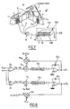
- This sensor module disposed between two mirror segments M ', M ", comprises an emitter plate T fixed on a side wall 1 of the segment M' and a receiver plate R fixed on a side wall 2 of the segment M", these two plates respectively transmitting and receiving T, R being substantially facing and parallel.
- the transmitting plate T comprises, on a flat support 3 of small thickness of insulating material, two emitter coils L1 and L3 of square shape, rectangular circular or other powered by the same current but in opposite directions.
- the receiving plate R comprises, on a flat support 4 of small thickness of insulating material, two receiving coils L2 and L4 of square shape, rectangular circular or other.
- the supports 3, 4 may be of dimensionally stable material such as zerodur®, which makes it possible to obtain the required dimensional stability.
- the supports may also be of flexible material, such as polyimide, bonded to the mirror.
- the bonding, with a thin resin, makes it possible to very greatly reduce the coefficient of thermal expansion of the sensor and to improve the dimensional stability of the flexible material supporting the sensor, thanks to the low coefficient of thermal expansion of the mirror.
- the flexible material can also be made with conventional flexible printed circuit.
- the sensor module is connected by one or more shielded cables 5 to an electronic processing module 10 installed in a rack 100 which can contain several electronic processing modules and disposed within a container 101.
- the shielded cable 5 is connected, d on the one hand, to electrical conductors connected to the sensor module by means of a first connector 6 and, on the other hand, to the container 101 by means of a second connector 8 and then to the electronic equipment 10 by means of a third connector 7.
- the rack 100 also includes a multi-channel acquisition module 102 connected to the various electronic processing modules 10 and to an external link bus 103.
- the arrangement of the sensor module between two mirror segments allows a measurement of quality because very close to the optical surfaces. Moreover, because of the remote nature of the electronic processing modules, there is no heat dissipation in the vicinity of the mirror segments.
- the analog calculation involves the quantity 1 / (Ma + Mb) which is a function of the axial distance between the transmitter and the receiver. It also involves the calculation of the quantity (Ma-Mb) / (Ma + Mb) which is a function of the radial distance between the transmitter and the receiver.
- Va represents the axial distance by keeping the sum va + vb constant via the multiplier.
- va-vb On the second radial calculation path, there is a differential amplifier A2 generating va-vb.
- the summator S4 receives this signal va-vb as well as a signal kr.Vref.Vr, where kr is a known coefficient and Vr is the radial dc voltage.
- the output of the summator S4 feeds a demodulator D4 followed by an integrator IT4, generating the radial DC voltage Vr.
- Va -ka / (Ma + Mb)
- Vr ka / kr . My - Mb / My + Mb
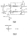
- the figure 9 describes a preferred embodiment in which the excitation signal e1 is no longer controlled by the axial DC voltage Va, but it is kept constant and is equal to the reference voltage Vref.
- the first axial channel comprises an analog multiplier-adder performing the following operation: goes + vb . Goes + ka . Vref in the same way as before, the output of m5 feeds a demodulator D5 followed by an integrator IT5, generating the axial DC voltage Va.
- the multiplier m5 like the multipliers m3, m4 and m6 described on the figures 8 and 9 , is a multiplier-summator operating as illustrated on the figure 10 .
- This multiplier comprises three inputs X, Y represented on the lateral inputs, and Z represented opposite the output W.
- This multiplier is of analog or digital type.
- the second radial channel comprises an analog multiplier performing the following operation: Vr . goes + vb + goes - vb in the same way as before, the output of m6 feeds a demodulator D6 followed by an integrator IT6, generating the radial DC voltage Vr.
Landscapes
- Physics & Mathematics (AREA)
- General Physics & Mathematics (AREA)
- Engineering & Computer Science (AREA)
- Power Engineering (AREA)
- Measurement Of Length, Angles, Or The Like Using Electric Or Magnetic Means (AREA)
Claims (42)
- Verfahren zur kontaktlosen Messung einer Relativbewegung oder einer Relativpositionierung eines ersten Objektes (M') gegenüber einem zweiten Objekt (M"), wobei:- wenigstens eine Sendespule (L1), die an dem ersten Objekt angeordnet ist, durch ein Erregungswechselsignal erregt wird,- wenigstens zwei Empfangsspulen (L2, L4) verwendet werden, die eine Wechselspannung va, welche zu der Gegeninduktivität Ma zwischen einer ersten Empfangsspule (L2) und der wenigstens einen Sendespule (L1) proportional ist, bzw. eine Wechselspannung vb, welche zu der Gegeninduktivität Mb zwischen einer zweiten Empfangsspule (L4) und der wenigstens einen Sendespule (L1) proportional ist, erzeugen,dadurch gekennzeichnet, dass man bestimmt:- eine axiale Entfernungsbewegung zwischen dem ersten Objekt (M') und dem zweiten Objekt (M") durch Messen einer axialen Gleichspannung Va, die zu einer monotonen Funktion der Summe der Gegeninduktivitäten Ma und Mb proportional ist, und- eine radiale Versatzbewegung zwischen dem ersten Objekt (M') und dem zweiten Objekt (M") durch Messen einer radialen Gleichspannung Vr, die zu der Beziehung (Ma-Mb).f(Ma+Mb) proportional ist, wobei (Ma-Mb) die Differenz der Gegeninduktivitäten Ma und Mb ist, wobei f(Ma+Mb) eine monotone Funktion der Summe (Ma+Mb) der Gegeninduktivitäten Ma und Mb ist.
- Verfahren nach Anspruch 1, dadurch gekennzeichnet, dass die wenigstens eine Sendespule (L1) und die Empfangsspulen (L2, L4) vom flachen oder planaren Typ sind, wobei die wenigstens eine Sendespule (L1) gegenüber der wenigstens einen Empfangsspule (L2) angeordnet ist.
- Verfahren nach Anspruch 2, dadurch gekennzeichnet, dass die wenigstens eine Sendespule (L1) und die Empfangsspulen (L2, L4) im Wesentlichen gegenüberliegend und parallel sind.
- Verfahren nach Anspruch 2 oder 3, dadurch gekennzeichnet, dass die Gesamtfläche, welche die Sendespulen aufweisen, kleiner ist als die Gesamtfläche, welche die Empfangsspulen aufweisen.
- Verfahren nach einem der vorhergehenden Ansprüche, dadurch gekennzeichnet, dass die wenigstens eine Sendespule und die Empfangsspulen einen Transformator bilden.
- Verfahren nach einem der vorhergehenden Ansprüche, dadurch gekennzeichnet, dass die monotone Funktion aus einer inversen Funktion besteht.
- Verfahren nach einem der vorhergehenden Ansprüche, dadurch gekennzeichnet, dass die Amplitude des Erregungssignals der wenigstens einen Sendespule von der axialen Gleichspannung Va abhängig ist.
- Verfahren nach einem der Ansprüche 1 bis 5, dadurch gekennzeichnet, dass die Amplitude des Erregungssignals konstant gehalten wird und zur Messung der Relativbewegung Mittel zum Berechnen der Gleichspannung Va von dieser axialen Gleichspannung Va abhängig sind.
- Verfahren nach einem der vorhergehenden Ansprüche, dadurch gekennzeichnet, dass zwei Sendespulen verwendet werden, für eine gegebene Position der Spulen am Ausgang der Empfangsspulen eine Induktivitätsausgleichsspannung bestimmt wird und die radiale Positionierung der beiden Objekte der Ausgleichsspannung unterworfen wird.
- Verfahren nach Anspruch 9, dadurch gekennzeichnet, dass die Ausgleichsspannung null ist.
- Verfahren nach Anspruch 9 oder 10, dadurch gekennzeichnet, dass die beiden Spulen durch zwei entgegengesetzte Erregungssignale erregt werden.
- Verfahren nach einem der vorhergehenden Ansprüche, dadurch gekennzeichnet, dass Differentialspulen verwendet werden.
- Verfahren nach einem der vorhergehenden Ansprüche, dadurch gekennzeichnet, dass die Spulen eine rechteckige, quadratische oder kreisförmige Form aufweisen.
- Verfahren nach einem der vorhergehenden Ansprüche, dadurch gekennzeichnet, dass die Spulen in Form von direkt auf die Objekte aufgebrachten Windungen ausgebildet werden.
- Verfahren nach einem der Ansprüche 1 bis 13, dadurch gekennzeichnet, dass die Spulen in Form von auf flexible Schaltungen aufgebrachten Windungen ausgebildet werden, wobei diese flexiblen Schaltungen auf den Objekten angeordnet sind.
- Verfahren nach einem der vorhergehenden Ansprüche, dadurch gekennzeichnet, dass die Spulen auf ein Material aufgebracht sind, das einen sehr geringen Wärmeausdehnungskoeffizienten aufweist, um die Verformung dieser aufgebrachten Spulen stark zu reduzieren.
- Verfahren nach einem der vorhergehenden Ansprüche, dadurch gekennzeichnet, dass das Erregungswechselsignal eine Wechselspannung ist.
- Verfahren nach einem der Ansprüche 1 bis 16, dadurch gekennzeichnet, dass das Erregungswechselsignal ein Wechselstrom ist.
- Verfahren nach einem der vorhergehenden Ansprüche, dadurch gekennzeichnet, dass das elektrische Ausgangswechselsignal eine Wechselspannung ist.
- Verfahren nach einem der Ansprüche 1 bis 18, dadurch gekennzeichnet, dass das elektrische Ausgangswechselsignal ein Wechselstrom ist.
- Verfahren nach einem der vorhergehenden Ansprüche, dadurch gekennzeichnet, dass die Sende- und die Empfangsspule jeweils auf zwei benachbarten Seitenflächen von zwei Spiegeln eines Teleskops angeordnet sind.
- System zur Messung einer Relativbewegung oder einer Relativpositionierung eines ersten Objektes (M') gegenüber einem zweiten Objekt (M"), umfassend:- wenigstens eine Sendespule (L1), die an dem ersten Objekt angeordnet ist,- wenigstens zwei Empfangsspulen (L2, L4), die an dem zweiten Objekt angeordnet sind,- Mittel zur Erregung der wenigstens einen Sendespule (L1) mit einem Erregungswechselsignal sowie- Verarbeitungsmittel, um eine Wechselspannung va, welche zu der Gegeninduktivität Ma zwischen einer ersten Empfangsspule (L2) und der wenigstens einen Sendespule (L1) proportional ist, bzw. eine Wechselspannung vb, welche zu der Gegeninduktivität Mb zwischen einer zweiten Empfangsspule (L4) und der wenigstens einen Sendespule (L1) proportional ist, zu gewinnen,dadurch gekennzeichnet, dass es ferner umfasst:- Mittel zum Bestimmen einer axialen Entfernungsbewegung zwischen dem ersten Objekt (M') und dem zweiten Objekt (M") durch Messen einer axialen Gleichspannung Va, die zu einer monotonen Funktion der Summe der Gegeninduktivitäten Ma und Mb proportional ist, und- Mittel zum Bestimmen einer radialen Versatzbewegung zwischen dem ersten Objekt (M') und dem zweiten Objekt (M") durch Messen einer radialen Gleichspannung Vr, die zu der Beziehung (Ma-Mb).f(Ma+Mb) proportional ist, wobei (Ma-Mb) die Differenz der Gegeninduktivitäten Ma und Mb ist, wobei f(Ma+Mb) eine monotone Funktion der Summe (Ma+Mb) der Gegeninduktivitäten Ma und Mb ist.
- System nach Anspruch 22, dadurch gekennzeichnet, dass die wenigstens eine Sendespule (L1) und die Empfangsspulen (L2, L4) vom flachen oder planaren Typ sind, wobei die wenigstens eine Sendespule (L1) gegenüber der wenigstens einen Empfangsspule (L2) angeordnet ist.
- System nach Anspruch 22, dadurch gekennzeichnet, dass es zwei Sendespulen umfasst, die mit zwei entgegengesetzten Erregungssignalen gespeist werden, um eine Kontrolle der radialen Positionierung durchzuführen.
- System nach Anspruch 22, dadurch gekennzeichnet, dass es zwei Sendespulen umfasst, die in Reihe mit einem gleichen Wechselstrom gespeist werden.
- System nach einem der Ansprüche 22 bis 25, dadurch gekennzeichnet, dass es zwei in Reihe geschaltete Empfangsspulen umfasst, um die Summe der beiden Gegeninduktivitäten zwischen jeder Empfangsspule und der wenigstens einen Sendespule zu bestimmen.
- System nach einem der Ansprüche 22 bis 25, dadurch gekennzeichnet, dass es zwei differentiell geschaltete Empfangsspulen umfasst, um die Differenz der beiden Gegeninduktivitäten zwischen jeder Empfangsspule und der wenigstens einen Sendespule zu bestimmen.
- System nach einem der Ansprüche 22 bis 27, dadurch gekennzeichnet, dass die Berechnungsmittel umfassen:- einen Summierer, um die Differenz der Wechselspannungen va-vb der beiden Empfangsspulen mit einem Rückkopplungssignal zu summieren,- einen Demodulator, um das von dem Summierer stammende Signal zu demodulieren,- einen Integrierer, um die radiale Gleichspannung Vr anhand des von dem Demodulator stammenden Signals zu erzeugen, und- einen Multiplikator, der mit der radialen Gleichspannung Vr und einer Referenzspannung Vref gespeist wird, um das Rückkopplungssignal zu erzeugen, wobei die Relativbewegung von dem Wert der radialen Gleichspannung Vr, bei der die Ausgabe des Multiplikators null ist, abhängig ist.
- System nach einem der Ansprüche 22 bis 27, dadurch gekennzeichnet, dass die Berechnungsmittel umfassen:- einen Multiplikator-Summierer, um die Differenz va-vb der durch die Empfangsspulen erzeugten Spannungen mit einem Rückkopplungssignal, das mit der Summe va+vb der durch die Empfangsspulen erzeugten Spannungen multipliziert wird, zu summieren,- einen Demodulator, um das von dem Multiplikator stammende Signal zu demodulieren, und- einen Integrierer, um die radiale Gleichspannung Vr anhand des von dem Demodulator stammenden Signals zu erzeugen, wobei das Rückkopplungssignal die radiale Gleichspannung Vr ist, wobei die Relativbewegung von dem Wert der radialen Gleichspannung Vr, bei der die Ausgabe des Multiplikators null ist, abhängig ist.
- System nach einem der Ansprüche 22 bis 29, dadurch gekennzeichnet, dass die monotone Funktion aus einer inversen Funktion besteht.
- System nach Anspruch 22, dadurch gekennzeichnet, dass die Berechnungsmittel umfassen:- einen Summierer, um die Summe der Wechselspannungen va+vb der beiden Empfangsspulen mit einer Referenzspannung Vref zu summieren,- einen Demodulator, um das von dem Summierer stammende Signal zu demodulieren,- einen Integrierer, um die axiale Gleichspannung Va anhand des von dem Demodulator stammenden Signals zu erzeugen, und- einen Multiplikator, der mit der axialen Gleichspannung Va und der Referenzspannung Vref gespeist wird, um das Erregungssignal zu erzeugen, wobei die Relativbewegung von dem Wert von Va, bei dem die Ausgabe des Summierers null ist, abhängig ist.
- System nach Anspruch 22, dadurch gekennzeichnet, dass die Berechnungsmittel umfassen:- einen Multiplikator-Summierer, um eine Referenzspannung Vref mit einem Rückkopplungssignal, das mit der Summe va+vb der durch die Empfangsspulen erzeugten Spannungen multipliziert wird, zu summieren,- einen Demodulator, um das von dem Multiplikator stammende Signal zu demodulieren, und- einen Integrierer, um die axiale Gleichspannung Va anhand des von dem Demodulator stammenden Signals zu erzeugen, wobei das Rückkopplungssignal die axiale Gleichspannung Va ist, wobei die Relativbewegung von dem Wert der axialen Gleichspannung Va, bei der die Ausgabe des Multiplikators null ist, abhängig ist.
- System nach Anspruch 28, 31 oder 32, dadurch gekennzeichnet, dass für jede Berechnung die Referenzspannung Vref mit einem Koeffizienten (kr, ka) multipliziert wird.
- System nach einem der Ansprüche 22 bis 33, dadurch gekennzeichnet, dass die Verarbeitungsmittel einen Summierverstärker umfassen, der geeignet ist, die Summe va+vb von durch die Empfangsspulen erzeugten Spannungen zu bilden.
- System nach einem der Ansprüche 22 bis 34, dadurch gekennzeichnet, dass die Verarbeitungsmittel einen Differentialverstärker umfassen, der geeignet ist, die Differenz va-vb von durch die Empfangsspulen erzeugten Spannungen zu bilden.
- Anwendung des Verfahrens nach einem der Ansprüche 1 bis 21, zur Positionskontrolle der segmentierten Spiegel für ein Teleskop.
- Anwendung des Verfahrens nach einem der Ansprüche 1 bis 21, zur Kontrolle der Ausrichtung der segmentierten Spiegel für ein Teleskop.
- Anwendung des kontaktlosen Messsystems nach einem der Ansprüche 22 bis 35, zur Messung der Relativposition zwischen zwei benachbarten Spiegelsegmenten.
- Anwendung nach Anspruch 38, wobei eine Sende- bzw. eine Empfangsplatte an gegenüberüberliegenden Seitenwänden von zwei benachbarten Spiegelsegmenten, in enger Nähe der aktiven Flächen der Spiegelsegmente befestigt sind.
- Anwendung nach Anspruch 39, wobei das kontaktlose Messsystem nach einem der Ansprüche 22 bis 35 für die Positionskontrolle (Tilt, Tip, Kolben und Gesamtkrümmungsradius des Spiegels (GROC)) von Spiegelsegmenten eingesetzt wird.
- Anwendung nach einem der Ansprüche 38 bis 40, auf dem Gebiet von großen Teleskopen mit segmentierten Spiegeln.
- Anwendung des kontaktlosen Messsystems nach einem der Ansprüche 22 bis 35, für die kontaktlose Positions- und ein- oder zweiachsige Bewegungsmessung.
Applications Claiming Priority (2)
| Application Number | Priority Date | Filing Date | Title |
|---|---|---|---|
| FR0507270A FR2888319B1 (fr) | 2005-07-07 | 2005-07-07 | Procede de mesure sans contact d'un deplacement relatif ou d'un positionnement relatif d'un premier objet par rapport a un second objet, par voie inductive. |
| PCT/FR2006/001591 WO2007006910A1 (fr) | 2005-07-07 | 2006-07-05 | Procede de mesure sans contact d'un deplacement relatif ou d'un positionnement relatif d'un premier objet par rapport a un second objet, par voie inductive |
Publications (3)
| Publication Number | Publication Date |
|---|---|
| EP1904806A1 EP1904806A1 (de) | 2008-04-02 |
| EP1904806B1 EP1904806B1 (de) | 2013-03-06 |
| EP1904806B2 true EP1904806B2 (de) | 2016-11-16 |
Family
ID=35986472
Family Applications (1)
| Application Number | Title | Priority Date | Filing Date |
|---|---|---|---|
| EP06778772.1A Active EP1904806B2 (de) | 2005-07-07 | 2006-07-05 | Induktive kontaktlose messung einer relativbewegung oder relativen positionierung eines ersten objekts relativ zu einem zweiten objekt |
Country Status (4)
| Country | Link |
|---|---|
| US (1) | US8159213B2 (de) |
| EP (1) | EP1904806B2 (de) |
| FR (1) | FR2888319B1 (de) |
| WO (1) | WO2007006910A1 (de) |
Families Citing this family (47)
| Publication number | Priority date | Publication date | Assignee | Title |
|---|---|---|---|---|
| US8381135B2 (en) | 2004-07-30 | 2013-02-19 | Apple Inc. | Proximity detector in handheld device |
| US7920129B2 (en) | 2007-01-03 | 2011-04-05 | Apple Inc. | Double-sided touch-sensitive panel with shield and drive combined layer |
| ES2307450A1 (es) * | 2008-04-16 | 2008-11-16 | Universidad Politecnica De Madrid | Dispositivo magnetico sensor de posicion. |
| DE102009009061A1 (de) * | 2009-01-21 | 2010-07-29 | Gerd Reime | Verfahren zum induktiven Erzeugen eines elektrischen Messsignals sowie zugehörige Sensorvorrichtung |
| DE102009022992A1 (de) | 2009-03-02 | 2010-10-07 | Micro-Epsilon Messtechnik Gmbh & Co. Kg | Positionssensor |
| FR2949007B1 (fr) | 2009-08-07 | 2012-06-08 | Nanotec Solution | Dispositif et procede d'interface de commande sensible a un mouvement d'un corps ou d'un objet et equipement de commande integrant ce dispositif. |
| GB2475841B (en) * | 2009-12-01 | 2012-05-30 | Wfs Technologies Ltd | Precision alignment system |
| US20110133726A1 (en) * | 2009-12-09 | 2011-06-09 | Alexander Ballantyne | Precision alignment system |
| DE102010031147A1 (de) * | 2010-05-07 | 2011-11-10 | Robert Bosch Gmbh | Erfassung eines metallischen oder magnetischen Objekts |
| FR2971066B1 (fr) | 2011-01-31 | 2013-08-23 | Nanotec Solution | Interface homme-machine tridimensionnelle. |
| FR2976688B1 (fr) | 2011-06-16 | 2021-04-23 | Nanotec Solution | Dispositif et procede pour generer une alimentation electrique dans un systeme electronique avec un potentiel de reference variable. |
| US9259904B2 (en) | 2011-10-20 | 2016-02-16 | Apple Inc. | Opaque thin film passivation |
| FR2985048B1 (fr) | 2011-12-21 | 2014-08-15 | Nanotec Solution | Dispositif et procede de mesure capacitive sensible a la pression pour interfaces tactiles et sans contact |
| FR2985049B1 (fr) | 2011-12-22 | 2014-01-31 | Nanotec Solution | Dispositif de mesure capacitive a electrodes commutees pour interfaces tactiles et sans contact |
| FR2988176B1 (fr) | 2012-03-13 | 2014-11-21 | Nanotec Solution | Procede de mesure capacitive entre un objet et un plan d’electrodes par demodulation synchrone partielle |
| FR2988175B1 (fr) | 2012-03-13 | 2014-04-11 | Nanotec Solution | Procede de mesure capacitive par des electrodes non-regulieres, et appareil mettant en œuvre un tel procede |
| US9201547B2 (en) | 2012-04-30 | 2015-12-01 | Apple Inc. | Wide dynamic range capacitive sensing |
| EP2728217B1 (de) * | 2012-11-02 | 2019-08-21 | ContiTech USA, Inc. | Luftfederhöhenmessungsanordnung |
| FR3002052B1 (fr) | 2013-02-14 | 2016-12-09 | Fogale Nanotech | Procede et dispositif pour naviguer dans un ecran d'affichage et appareil comprenant une telle navigation |
| FR3003964B1 (fr) | 2013-04-02 | 2016-08-26 | Fogale Nanotech | Dispositif pour interagir, sans contact, avec un appareil electronique et/ou informatique, et appareil equipe d'un tel dispositif |
| FR3004551A1 (fr) | 2013-04-15 | 2014-10-17 | Fogale Nanotech | Procede de detection capacitif multizone, dispositif et appareil mettant en oeuvre le procede |
| FR3005763B1 (fr) | 2013-05-17 | 2016-10-14 | Fogale Nanotech | Dispositif et procede d'interface de commande capacitive adapte a la mise en œuvre d'electrodes de mesures fortement resistives |
| EP3004808B1 (de) * | 2013-06-07 | 2018-05-16 | Atlas Copco Industrial Technique AB | Drehcodierer |
| FR3008809B1 (fr) | 2013-07-18 | 2017-07-07 | Fogale Nanotech | Dispositif accessoire garde pour un appareil electronique et/ou informatique, et appareil equipe d'un tel dispositif accessoire |
| FR3013472B1 (fr) | 2013-11-19 | 2016-07-08 | Fogale Nanotech | Dispositif accessoire couvrant pour un appareil portable electronique et/ou informatique, et appareil equipe d'un tel dispositif accessoire |
| DE102013226201A1 (de) * | 2013-12-17 | 2015-06-18 | Robert Bosch Gmbh | Linearführung mit kombinierter Last- und Positionsmessung |
| FR3017723B1 (fr) | 2014-02-19 | 2017-07-21 | Fogale Nanotech | Procede d'interaction homme-machine par combinaison de commandes tactiles et sans contact |
| FR3019320B1 (fr) | 2014-03-28 | 2017-12-15 | Fogale Nanotech | Dispositif electronique de type montre-bracelet avec interface de commande sans contact et procede de controle d'un tel dispositif |
| FR3025623B1 (fr) | 2014-09-05 | 2017-12-15 | Fogale Nanotech | Dispositif d'interface de commande et capteur d'empreintes digitales |
| FR3028061B1 (fr) | 2014-10-29 | 2016-12-30 | Fogale Nanotech | Dispositif capteur capacitif comprenant des electrodes ajourees |
| FR3028942B1 (fr) * | 2014-11-26 | 2016-12-23 | Continental Automotive France | Capteur inductif de mesure de la position d'un arbre d'un vehicule |
| FR3032287B1 (fr) | 2015-02-04 | 2018-03-09 | Quickstep Technologies Llc | Dispositif de detection capacitif multicouches, et appareil comprenant le dispositif |
| FR3033203B1 (fr) | 2015-02-27 | 2018-03-23 | Quickstep Technologies Llc | Procede pour interagir avec un appareil electronique et/ou informatique mettant en œuvre une surface de commande capacitive et une surface peripherique, interface et appareil mettant en œuvre ce procede |
| DE102016206782A1 (de) | 2016-04-21 | 2017-10-26 | Micro-Epsilon Messtechnik Gmbh & Co. Kg | Messanordnung zur kontaktlosen Messung einer Relativbewegung oder einer Relativposition und Verfahren |
| US10024880B2 (en) * | 2016-05-21 | 2018-07-17 | Raytheon Company | Athermal hung mass accelerometer with reduced sensitivity to longitudinal temperature gradients |
| US10429974B2 (en) | 2016-09-23 | 2019-10-01 | Apple Inc. | Touch sensor panel with top and/or bottom shielding |
| US10372282B2 (en) | 2016-12-01 | 2019-08-06 | Apple Inc. | Capacitive coupling reduction in touch sensor panels |
| WO2018158918A1 (ja) * | 2017-03-02 | 2018-09-07 | 三菱電機株式会社 | 位置検出装置及び電力伝送装置 |
| US11525701B2 (en) | 2018-01-22 | 2022-12-13 | Melexis Technologies Sa | Inductive position sensor |
| EP3514502B1 (de) * | 2018-01-22 | 2021-07-14 | Melexis Technologies SA | Induktiver positionssensor |
| WO2020095354A1 (ja) * | 2018-11-06 | 2020-05-14 | 株式会社島津製作所 | 磁性体検査装置および磁性体検査システム |
| WO2020157390A1 (fr) * | 2019-01-31 | 2020-08-06 | Osmos Group | Procédé et dispositif pour mesurer la position et/ou le déplacement de deux sites l'un par rapport à l'autre |
| US11531438B2 (en) | 2020-05-29 | 2022-12-20 | Apple Inc. | Differential drive and sense for touch sensor panel |
| US12260045B2 (en) | 2021-09-24 | 2025-03-25 | Apple Inc. | Architecture for differential drive and sense for touch sensor panel |
| US11789561B2 (en) | 2021-09-24 | 2023-10-17 | Apple Inc. | Architecture for differential drive and sense touch technology |
| US12197679B2 (en) | 2022-05-06 | 2025-01-14 | Apple Inc. | Touch screen shield layer with ring and tapping points |
| WO2025116000A1 (ja) * | 2023-12-01 | 2025-06-05 | 株式会社Premo | 情報処理装置 |
Family Cites Families (13)
| Publication number | Priority date | Publication date | Assignee | Title |
|---|---|---|---|---|
| US3121228A (en) * | 1961-05-01 | 1964-02-11 | Henry P Kalmus | Direction indicator |
| FR1512207A (fr) * | 1966-02-23 | 1968-02-02 | Montan Forschung Dr Hans Zille | Dispositif de mesure électrique de grandeurs mécaniques |
| SE406642B (sv) * | 1977-02-16 | 1979-02-19 | Aga Ab | Elektromekanisk legesgivare |
| JPS57135917U (de) * | 1981-02-20 | 1982-08-25 | ||
| JPH0654242B2 (ja) * | 1987-04-30 | 1994-07-20 | 株式会社エスジ− | 位置検出装置 |
| US4816759A (en) * | 1987-10-28 | 1989-03-28 | Kaman Corporation | Inductive sensor for detecting displacement of adjacent surfaces |
| US5087866A (en) * | 1991-05-22 | 1992-02-11 | Lucas Industries | Temperature compensating circuit for LVDT and control system |
| US5617023A (en) * | 1995-02-02 | 1997-04-01 | Otis Elevator Company | Industrial contactless position sensor |
| JP3849829B2 (ja) * | 1998-04-27 | 2006-11-22 | 株式会社デンソー | 車高センサ及び車両用前照灯光軸調整装置 |
| GB9811151D0 (en) * | 1998-05-22 | 1998-07-22 | Scient Generics Ltd | Rotary encoder |
| CN1483136A (zh) * | 2000-11-30 | 2004-03-17 | 阿赛勒姆研究股份有限公司 | 用于高精度位置测量的改进线性变量差接变压器 |
| FR2844048B1 (fr) * | 2002-08-30 | 2005-09-30 | Nanotec Solution | Systeme et procede de mesure sans contact d'un deplacement ou positionnement relatif de deux objets adjacents par voie capacitive, et application au controle de miroirs |
| JP5189510B2 (ja) * | 2009-01-22 | 2013-04-24 | 愛三工業株式会社 | 位置センサ |
-
2005
- 2005-07-07 FR FR0507270A patent/FR2888319B1/fr not_active Expired - Fee Related
-
2006
- 2006-07-05 WO PCT/FR2006/001591 patent/WO2007006910A1/fr not_active Ceased
- 2006-07-05 US US11/994,817 patent/US8159213B2/en active Active
- 2006-07-05 EP EP06778772.1A patent/EP1904806B2/de active Active
Also Published As
| Publication number | Publication date |
|---|---|
| US20090140729A1 (en) | 2009-06-04 |
| WO2007006910A1 (fr) | 2007-01-18 |
| EP1904806B1 (de) | 2013-03-06 |
| FR2888319B1 (fr) | 2008-02-15 |
| FR2888319A1 (fr) | 2007-01-12 |
| EP1904806A1 (de) | 2008-04-02 |
| US8159213B2 (en) | 2012-04-17 |
Similar Documents
| Publication | Publication Date | Title |
|---|---|---|
| EP1904806B1 (de) | Induktive kontaktlose messung einer relativbewegung oder relativen positionierung eines ersten objekts relativ zu einem zweiten objekt | |
| EP3245484B1 (de) | Induktive bewegungssensoren | |
| EP3245483B1 (de) | Induktive bewegungssensoren | |
| EP3245482B1 (de) | Induktive bewegungssensoren | |
| FR2909756A1 (fr) | Systeme de detection de mouvement pour vehicule automobile. | |
| EP1518126A2 (de) | Mit einem sensor ausgestattetes antireibungslager und damit ausgestatteter elektromotor | |
| EP1584899B1 (de) | Positionssensor eines Ventilschalters an einem Verbrennungsmotor | |
| FR3100400A1 (fr) | Actionneur magnetique et systeme mecatronique | |
| FR3023611A1 (fr) | Ensemble comprenant un moteur de vehicule automobile comportant des cibles et un capteur de position angulaire | |
| FR2554223A1 (fr) | Jauge de hauteur a capacite et procede et appareil d'etalonnage de cette jauge | |
| EP2927647B1 (de) | Mit instrumenten ausgestattete linearführungsanlage | |
| WO2019048780A1 (fr) | Procédé de définition d'une plage de mesure d'un capteur de position inductif | |
| WO2001040736A1 (fr) | Capteur analogique de decalage angulaire sans contact | |
| Akutsu et al. | Compact integrated optical sensors and electromagnetic actuators for vibration isolation systems in the gravitational-wave detector KAGRA | |
| EP0637123A1 (de) | Akustischer Oberflächenwellenmotor | |
| EP1071927B1 (de) | Inkrementaler positionsgeber | |
| WO2019180182A1 (fr) | Procede de mesure d'une position d'un corps mobile par rapport a un corps fixe | |
| Liu et al. | A motion characteristics modeled angular position sensor by nonlinear transfer of differential capacitance for miniaturized scanning mirrors | |
| EP2828968A1 (de) | Mikropositionierungsvorrichtung mit mehreren freiheitsgraden für piezoelektrische aktuatoren und zugehörige verfahren | |
| FR2907211A1 (fr) | "dispositif inductif de mesure de la position d'une cible, et procede mis en oeuvre par ce dispositif" | |
| EP2511665A1 (de) | Vorrichtung zur axialen Positionserfassung einer Drehwelle, und Verwendung in einer Turbomolekularpumpe | |
| EP0866345B1 (de) | Photodetektor mit variabler achse | |
| FR2900735A1 (fr) | Micromagnetometre de type fluxgate a bobinage d'excitation ameliore | |
| EP1934559B1 (de) | Sensor und verfahren zur messung von position und geschwindigkeit | |
| FR2791487A1 (fr) | Procede pour la determination de la position d'un organe mobile dans au moins un entrefer principal d'un actionneur electromagnetique |
Legal Events
| Date | Code | Title | Description |
|---|---|---|---|
| PUAI | Public reference made under article 153(3) epc to a published international application that has entered the european phase |
Free format text: ORIGINAL CODE: 0009012 |
|
| 17P | Request for examination filed |
Effective date: 20080207 |
|
| AK | Designated contracting states |
Kind code of ref document: A1 Designated state(s): AT BE BG CH CY CZ DE DK EE ES FI FR GB GR HU IE IS IT LI LT LU LV MC NL PL PT RO SE SI SK TR |
|
| AX | Request for extension of the european patent |
Extension state: AL BA HR MK YU |
|
| RAX | Requested extension states of the european patent have changed |
Extension state: HR Payment date: 20080207 Extension state: MK Payment date: 20080207 Extension state: RS Payment date: 20080207 Extension state: AL Payment date: 20080207 Extension state: BA Payment date: 20080207 |
|
| 17Q | First examination report despatched |
Effective date: 20100216 |
|
| GRAP | Despatch of communication of intention to grant a patent |
Free format text: ORIGINAL CODE: EPIDOSNIGR1 |
|
| GRAS | Grant fee paid |
Free format text: ORIGINAL CODE: EPIDOSNIGR3 |
|
| GRAA | (expected) grant |
Free format text: ORIGINAL CODE: 0009210 |
|
| AK | Designated contracting states |
Kind code of ref document: B1 Designated state(s): AT BE BG CH CY CZ DE DK EE ES FI FR GB GR HU IE IS IT LI LT LU LV MC NL PL PT RO SE SI SK TR |
|
| AX | Request for extension of the european patent |
Extension state: AL BA HR MK RS |
|
| REG | Reference to a national code |
Ref country code: GB Ref legal event code: FG4D Free format text: NOT ENGLISH |
|
| REG | Reference to a national code |
Ref country code: CH Ref legal event code: EP Ref country code: AT Ref legal event code: REF Ref document number: 599890 Country of ref document: AT Kind code of ref document: T Effective date: 20130315 |
|
| REG | Reference to a national code |
Ref country code: IE Ref legal event code: FG4D Free format text: LANGUAGE OF EP DOCUMENT: FRENCH |
|
| REG | Reference to a national code |
Ref country code: DE Ref legal event code: R096 Ref document number: 602006034920 Country of ref document: DE Effective date: 20130425 |
|
| REG | Reference to a national code |
Ref country code: AT Ref legal event code: MK05 Ref document number: 599890 Country of ref document: AT Kind code of ref document: T Effective date: 20130306 |
|
| PG25 | Lapsed in a contracting state [announced via postgrant information from national office to epo] |
Ref country code: LT Free format text: LAPSE BECAUSE OF FAILURE TO SUBMIT A TRANSLATION OF THE DESCRIPTION OR TO PAY THE FEE WITHIN THE PRESCRIBED TIME-LIMIT Effective date: 20130306 Ref country code: ES Free format text: LAPSE BECAUSE OF FAILURE TO SUBMIT A TRANSLATION OF THE DESCRIPTION OR TO PAY THE FEE WITHIN THE PRESCRIBED TIME-LIMIT Effective date: 20130617 Ref country code: SE Free format text: LAPSE BECAUSE OF FAILURE TO SUBMIT A TRANSLATION OF THE DESCRIPTION OR TO PAY THE FEE WITHIN THE PRESCRIBED TIME-LIMIT Effective date: 20130306 Ref country code: BG Free format text: LAPSE BECAUSE OF FAILURE TO SUBMIT A TRANSLATION OF THE DESCRIPTION OR TO PAY THE FEE WITHIN THE PRESCRIBED TIME-LIMIT Effective date: 20130606 Ref country code: AT Free format text: LAPSE BECAUSE OF FAILURE TO SUBMIT A TRANSLATION OF THE DESCRIPTION OR TO PAY THE FEE WITHIN THE PRESCRIBED TIME-LIMIT Effective date: 20130306 |
|
| REG | Reference to a national code |
Ref country code: NL Ref legal event code: VDEP Effective date: 20130306 |
|
| REG | Reference to a national code |
Ref country code: LT Ref legal event code: MG4D |
|
| PG25 | Lapsed in a contracting state [announced via postgrant information from national office to epo] |
Ref country code: SI Free format text: LAPSE BECAUSE OF FAILURE TO SUBMIT A TRANSLATION OF THE DESCRIPTION OR TO PAY THE FEE WITHIN THE PRESCRIBED TIME-LIMIT Effective date: 20130306 Ref country code: GR Free format text: LAPSE BECAUSE OF FAILURE TO SUBMIT A TRANSLATION OF THE DESCRIPTION OR TO PAY THE FEE WITHIN THE PRESCRIBED TIME-LIMIT Effective date: 20130607 Ref country code: FI Free format text: LAPSE BECAUSE OF FAILURE TO SUBMIT A TRANSLATION OF THE DESCRIPTION OR TO PAY THE FEE WITHIN THE PRESCRIBED TIME-LIMIT Effective date: 20130306 Ref country code: LV Free format text: LAPSE BECAUSE OF FAILURE TO SUBMIT A TRANSLATION OF THE DESCRIPTION OR TO PAY THE FEE WITHIN THE PRESCRIBED TIME-LIMIT Effective date: 20130306 |
|
| PG25 | Lapsed in a contracting state [announced via postgrant information from national office to epo] |
Ref country code: IS Free format text: LAPSE BECAUSE OF FAILURE TO SUBMIT A TRANSLATION OF THE DESCRIPTION OR TO PAY THE FEE WITHIN THE PRESCRIBED TIME-LIMIT Effective date: 20130706 Ref country code: CZ Free format text: LAPSE BECAUSE OF FAILURE TO SUBMIT A TRANSLATION OF THE DESCRIPTION OR TO PAY THE FEE WITHIN THE PRESCRIBED TIME-LIMIT Effective date: 20130306 Ref country code: NL Free format text: LAPSE BECAUSE OF FAILURE TO SUBMIT A TRANSLATION OF THE DESCRIPTION OR TO PAY THE FEE WITHIN THE PRESCRIBED TIME-LIMIT Effective date: 20130306 Ref country code: SK Free format text: LAPSE BECAUSE OF FAILURE TO SUBMIT A TRANSLATION OF THE DESCRIPTION OR TO PAY THE FEE WITHIN THE PRESCRIBED TIME-LIMIT Effective date: 20130306 Ref country code: EE Free format text: LAPSE BECAUSE OF FAILURE TO SUBMIT A TRANSLATION OF THE DESCRIPTION OR TO PAY THE FEE WITHIN THE PRESCRIBED TIME-LIMIT Effective date: 20130306 Ref country code: RO Free format text: LAPSE BECAUSE OF FAILURE TO SUBMIT A TRANSLATION OF THE DESCRIPTION OR TO PAY THE FEE WITHIN THE PRESCRIBED TIME-LIMIT Effective date: 20130306 Ref country code: PT Free format text: LAPSE BECAUSE OF FAILURE TO SUBMIT A TRANSLATION OF THE DESCRIPTION OR TO PAY THE FEE WITHIN THE PRESCRIBED TIME-LIMIT Effective date: 20130708 |
|
| PG25 | Lapsed in a contracting state [announced via postgrant information from national office to epo] |
Ref country code: PL Free format text: LAPSE BECAUSE OF FAILURE TO SUBMIT A TRANSLATION OF THE DESCRIPTION OR TO PAY THE FEE WITHIN THE PRESCRIBED TIME-LIMIT Effective date: 20130306 Ref country code: CY Free format text: LAPSE BECAUSE OF FAILURE TO SUBMIT A TRANSLATION OF THE DESCRIPTION OR TO PAY THE FEE WITHIN THE PRESCRIBED TIME-LIMIT Effective date: 20130306 |
|
| PLBI | Opposition filed |
Free format text: ORIGINAL CODE: 0009260 |
|
| 26 | Opposition filed |
Opponent name: MICRO-EPSILON MESSTECHNIK GMBH & CO. KG Effective date: 20131205 |
|
| BERE | Be: lapsed |
Owner name: NANOTEC SOLUTION Effective date: 20130731 |
|
| PG25 | Lapsed in a contracting state [announced via postgrant information from national office to epo] |
Ref country code: DK Free format text: LAPSE BECAUSE OF FAILURE TO SUBMIT A TRANSLATION OF THE DESCRIPTION OR TO PAY THE FEE WITHIN THE PRESCRIBED TIME-LIMIT Effective date: 20130306 |
|
| PLAX | Notice of opposition and request to file observation + time limit sent |
Free format text: ORIGINAL CODE: EPIDOSNOBS2 |
|
| REG | Reference to a national code |
Ref country code: DE Ref legal event code: R026 Ref document number: 602006034920 Country of ref document: DE Effective date: 20131205 |
|
| PG25 | Lapsed in a contracting state [announced via postgrant information from national office to epo] |
Ref country code: IT Free format text: LAPSE BECAUSE OF FAILURE TO SUBMIT A TRANSLATION OF THE DESCRIPTION OR TO PAY THE FEE WITHIN THE PRESCRIBED TIME-LIMIT Effective date: 20130306 Ref country code: MC Free format text: LAPSE BECAUSE OF FAILURE TO SUBMIT A TRANSLATION OF THE DESCRIPTION OR TO PAY THE FEE WITHIN THE PRESCRIBED TIME-LIMIT Effective date: 20130306 |
|
| REG | Reference to a national code |
Ref country code: CH Ref legal event code: PL |
|
| GBPC | Gb: european patent ceased through non-payment of renewal fee |
Effective date: 20130705 |
|
| REG | Reference to a national code |
Ref country code: IE Ref legal event code: MM4A |
|
| PG25 | Lapsed in a contracting state [announced via postgrant information from national office to epo] |
Ref country code: BE Free format text: LAPSE BECAUSE OF NON-PAYMENT OF DUE FEES Effective date: 20130731 Ref country code: LI Free format text: LAPSE BECAUSE OF NON-PAYMENT OF DUE FEES Effective date: 20130731 Ref country code: GB Free format text: LAPSE BECAUSE OF NON-PAYMENT OF DUE FEES Effective date: 20130705 Ref country code: CH Free format text: LAPSE BECAUSE OF NON-PAYMENT OF DUE FEES Effective date: 20130731 |
|
| PLBB | Reply of patent proprietor to notice(s) of opposition received |
Free format text: ORIGINAL CODE: EPIDOSNOBS3 |
|
| PG25 | Lapsed in a contracting state [announced via postgrant information from national office to epo] |
Ref country code: IE Free format text: LAPSE BECAUSE OF NON-PAYMENT OF DUE FEES Effective date: 20130705 |
|
| REG | Reference to a national code |
Ref country code: FR Ref legal event code: PLFP Year of fee payment: 10 |
|
| PG25 | Lapsed in a contracting state [announced via postgrant information from national office to epo] |
Ref country code: TR Free format text: LAPSE BECAUSE OF FAILURE TO SUBMIT A TRANSLATION OF THE DESCRIPTION OR TO PAY THE FEE WITHIN THE PRESCRIBED TIME-LIMIT Effective date: 20130306 |
|
| PG25 | Lapsed in a contracting state [announced via postgrant information from national office to epo] |
Ref country code: LU Free format text: LAPSE BECAUSE OF NON-PAYMENT OF DUE FEES Effective date: 20130705 Ref country code: HU Free format text: LAPSE BECAUSE OF FAILURE TO SUBMIT A TRANSLATION OF THE DESCRIPTION OR TO PAY THE FEE WITHIN THE PRESCRIBED TIME-LIMIT; INVALID AB INITIO Effective date: 20060705 |
|
| PLAY | Examination report in opposition despatched + time limit |
Free format text: ORIGINAL CODE: EPIDOSNORE2 |
|
| PLBC | Reply to examination report in opposition received |
Free format text: ORIGINAL CODE: EPIDOSNORE3 |
|
| APBM | Appeal reference recorded |
Free format text: ORIGINAL CODE: EPIDOSNREFNO |
|
| APBP | Date of receipt of notice of appeal recorded |
Free format text: ORIGINAL CODE: EPIDOSNNOA2O |
|
| APAH | Appeal reference modified |
Free format text: ORIGINAL CODE: EPIDOSCREFNO |
|
| APBU | Appeal procedure closed |
Free format text: ORIGINAL CODE: EPIDOSNNOA9O |
|
| REG | Reference to a national code |
Ref country code: FR Ref legal event code: PLFP Year of fee payment: 11 |
|
| PUAH | Patent maintained in amended form |
Free format text: ORIGINAL CODE: 0009272 |
|
| STAA | Information on the status of an ep patent application or granted ep patent |
Free format text: STATUS: PATENT MAINTAINED AS AMENDED |
|
| 27A | Patent maintained in amended form |
Effective date: 20161116 |
|
| AK | Designated contracting states |
Kind code of ref document: B2 Designated state(s): AT BE BG CH CY CZ DE DK EE ES FI FR GB GR HU IE IS IT LI LT LU LV MC NL PL PT RO SE SI SK TR |
|
| AX | Request for extension of the european patent |
Extension state: AL BA HR MK RS |
|
| REG | Reference to a national code |
Ref country code: DE Ref legal event code: R102 Ref document number: 602006034920 Country of ref document: DE |
|
| PG25 | Lapsed in a contracting state [announced via postgrant information from national office to epo] |
Ref country code: LV Free format text: LAPSE BECAUSE OF FAILURE TO SUBMIT A TRANSLATION OF THE DESCRIPTION OR TO PAY THE FEE WITHIN THE PRESCRIBED TIME-LIMIT Effective date: 20161116 |
|
| REG | Reference to a national code |
Ref country code: FR Ref legal event code: PLFP Year of fee payment: 12 |
|
| REG | Reference to a national code |
Ref country code: DE Ref legal event code: R082 Ref document number: 602006034920 Country of ref document: DE Representative=s name: BSB ANWALTSKANZLEI, DE Ref country code: DE Ref legal event code: R081 Ref document number: 602006034920 Country of ref document: DE Owner name: FOGALE NANOTECH, FR Free format text: FORMER OWNER: NANOTEC SOLUTION, NIMES, FR Ref country code: DE Ref legal event code: R082 Ref document number: 602006034920 Country of ref document: DE Representative=s name: BSB PATENTANWAELTE SCHUETTE & ENGELEN PARTNERS, DE |
|
| REG | Reference to a national code |
Ref country code: FR Ref legal event code: TP Owner name: FOGALE NANOTECH, FR Effective date: 20180330 |
|
| REG | Reference to a national code |
Ref country code: FR Ref legal event code: PLFP Year of fee payment: 13 |
|
| PGFP | Annual fee paid to national office [announced via postgrant information from national office to epo] |
Ref country code: FR Payment date: 20200729 Year of fee payment: 15 Ref country code: DE Payment date: 20200721 Year of fee payment: 15 |
|
| REG | Reference to a national code |
Ref country code: DE Ref legal event code: R119 Ref document number: 602006034920 Country of ref document: DE |
|
| PG25 | Lapsed in a contracting state [announced via postgrant information from national office to epo] |
Ref country code: DE Free format text: LAPSE BECAUSE OF NON-PAYMENT OF DUE FEES Effective date: 20220201 |
|
| PG25 | Lapsed in a contracting state [announced via postgrant information from national office to epo] |
Ref country code: FR Free format text: LAPSE BECAUSE OF NON-PAYMENT OF DUE FEES Effective date: 20210731 |