EP1903681A1 - Method for synchronising the clock of an electrical apparatus with a reference clock and electrical apparatus - Google Patents
Method for synchronising the clock of an electrical apparatus with a reference clock and electrical apparatus Download PDFInfo
- Publication number
- EP1903681A1 EP1903681A1 EP06019806A EP06019806A EP1903681A1 EP 1903681 A1 EP1903681 A1 EP 1903681A1 EP 06019806 A EP06019806 A EP 06019806A EP 06019806 A EP06019806 A EP 06019806A EP 1903681 A1 EP1903681 A1 EP 1903681A1
- Authority
- EP
- European Patent Office
- Prior art keywords
- clock frequency
- clock
- time
- correction value
- difference
- Prior art date
- Legal status (The legal status is an assumption and is not a legal conclusion. Google has not performed a legal analysis and makes no representation as to the accuracy of the status listed.)
- Granted
Links
- 238000000034 method Methods 0.000 title claims abstract description 33
- 238000012937 correction Methods 0.000 claims abstract description 43
- 238000004590 computer program Methods 0.000 claims abstract description 12
- 238000012545 processing Methods 0.000 claims description 10
- 230000001360 synchronised effect Effects 0.000 description 4
- 230000000694 effects Effects 0.000 description 3
- 230000032683 aging Effects 0.000 description 2
- 238000004891 communication Methods 0.000 description 2
- 230000001419 dependent effect Effects 0.000 description 2
- 238000011161 development Methods 0.000 description 2
- 230000018109 developmental process Effects 0.000 description 2
- 238000012986 modification Methods 0.000 description 2
- 230000004048 modification Effects 0.000 description 2
- 238000012935 Averaging Methods 0.000 description 1
- 239000000654 additive Substances 0.000 description 1
- 230000000996 additive effect Effects 0.000 description 1
- 230000005684 electric field Effects 0.000 description 1
- 230000007613 environmental effect Effects 0.000 description 1
- 238000009472 formulation Methods 0.000 description 1
- 238000010438 heat treatment Methods 0.000 description 1
- 238000004519 manufacturing process Methods 0.000 description 1
- 239000000203 mixture Substances 0.000 description 1
Images


Classifications
-
- H—ELECTRICITY
- H03—ELECTRONIC CIRCUITRY
- H03K—PULSE TECHNIQUE
- H03K5/00—Manipulating of pulses not covered by one of the other main groups of this subclass
- H03K5/13—Arrangements having a single output and transforming input signals into pulses delivered at desired time intervals
- H03K5/135—Arrangements having a single output and transforming input signals into pulses delivered at desired time intervals by the use of time reference signals, e.g. clock signals
-
- H—ELECTRICITY
- H03—ELECTRONIC CIRCUITRY
- H03L—AUTOMATIC CONTROL, STARTING, SYNCHRONISATION, OR STABILISATION OF GENERATORS OF ELECTRONIC OSCILLATIONS OR PULSES
- H03L7/00—Automatic control of frequency or phase; Synchronisation
- H03L7/06—Automatic control of frequency or phase; Synchronisation using a reference signal applied to a frequency- or phase-locked loop
- H03L7/07—Automatic control of frequency or phase; Synchronisation using a reference signal applied to a frequency- or phase-locked loop using several loops, e.g. for redundant clock signal generation
-
- H—ELECTRICITY
- H03—ELECTRONIC CIRCUITRY
- H03L—AUTOMATIC CONTROL, STARTING, SYNCHRONISATION, OR STABILISATION OF GENERATORS OF ELECTRONIC OSCILLATIONS OR PULSES
- H03L7/00—Automatic control of frequency or phase; Synchronisation
- H03L7/06—Automatic control of frequency or phase; Synchronisation using a reference signal applied to a frequency- or phase-locked loop
- H03L7/08—Details of the phase-locked loop
- H03L7/085—Details of the phase-locked loop concerning mainly the frequency- or phase-detection arrangement including the filtering or amplification of its output signal
- H03L7/091—Details of the phase-locked loop concerning mainly the frequency- or phase-detection arrangement including the filtering or amplification of its output signal the phase or frequency detector using a sampling device
Definitions
- the invention relates to a method for operating an electrical device, in particular an automation device, in which a correction of a clock frequency. It further relates to an electrical device, in particular an automation device, with means for carrying out the method.
- clock signals are generated, for example, by means of oscillators, wherein a regularity of the clock signals depends on a quality of the components used and on other factors, including aging processes of the components or environmental factors, e.g. Temperature or humidity, count, is affected.
- Very regular clock signals are based on atomic vibrations, which ensures high precision in atomic clocks.
- An object of the invention is to provide a method in which the abovementioned disadvantages are avoided or at least reduced in terms of their effects.
- This object is achieved by a method for operating an electrical device, in particular an automation device, in which a correction of a first clock frequency based on a second clock frequency and a reference clock frequency.
- a clock difference between the second clock frequency and the reference clock frequency is determined at least one predetermined or predefinable first time. From this clock difference, a correction value is derived, with which the first clock frequency is applied.
- a correction value is derived, with which the first clock frequency is applied.
- this object is achieved by a computer program with program code instructions for implementing the method when the computer program is executed on a computer, and by a computer program product, in particular storage medium, with the computer-executable computer program.
- an electrical device in particular an automation device, having means for carrying out the method, in particular a processing unit and a memory assigned to the processing unit.
- the computer program executable by the processing unit is stored in the memory.
- a regular and with the reference clock frequency substantially synchronous first clock frequency is generated at a lower frequency of synchronization, by means of which, for example, a drift is compensated.
- This lower frequency results in a minimization of the additional communication required for synchronization in the automation system. If the synchronization takes place permanently and automatically, an automatic calibration results without any external impact, e.g. an activity of the user, would be required, resulting in an increase in ease of use of the automation system.
- the second clock frequency is synchronized with the reference clock frequency at the or each predetermined or predefinable first time.
- the clock difference between the second clock frequency and the reference clock frequency is determined in connection with the synchronization of the second clock frequency with the reference clock frequency.
- a difference can be indicated, for example, as a difference of the second clock frequency and the reference clock frequency at any desired time, that is to say a relative difference, or as a totality for a period after the synchronization of determined differences, ie an absolute difference.
- a synchronization of the second clock frequency with the reference clock frequency resets the absolute difference of the clock frequencies, thus facilitating the determination of the correction value with which the first clock frequency is applied and reduces a possible error in the determination of the correction value which results from very large values of the difference would. If the clock difference in connection with the synchronization, ie, timely to a synchronization time is determined, then the clock difference between the second clock frequency and reference clock frequency has a maximum possible value for this method, thereby reducing a potential error in the determination of the clock difference and subsequently the correction value becomes.
- a synchronization of the first and the second clock frequency with the reference clock frequency takes place at least one predetermined or predefinable second time. This results in a simplification of the application of the first clock frequency with the mathematically or logically derived correction value from the clock difference between the second clock frequency and the reference clock frequency as well as a lesser potential error since there is no additive or multiplicative increase in the error.
- At least one correction value is determined for the first and at least one further time, at least one mean correction value is formed from the determined correction values and the first clock frequency is applied to the mean correction value, the average correction value is improved with each correction value used for its determination.
- an improvement in the correction value is achieved, and as the number of averaged correction values increases, an improvement in the synchronism of the first clock frequency and reference clock frequency and thus an improvement in quality is achieved.
- a first point in time and at least two further points in time are arranged equidistant from each other on a time axis, wherein in each case two successive points in time include a time interval.
- the correction value is determined in each case for such a time interval or at least a part thereof.
- the clock difference can be averaged or integrated over the entire time interval or at least part of the time interval.
- clock differences and / or correction values are averaged or integrated over a plurality of time intervals or parts thereof.
- either the clock difference or the correction value derived therefrom is related to a number of clocks of the reference clock frequency, via which either the clock difference or the correction value has been integrated or averaged. If the clock difference or the correction value has been determined or determined at a first time and this time is assigned to a preceding time interval, then the clock difference or the correction value is related to the number of reference clock frequency clocks of the time interval. This results in a correction value per clock for applying the first clock frequency.
- the first and the second clock frequency are selected so that a difference of these clock frequencies remains substantially the same.
- a deviation between the first clock frequency and the second clock frequency remains constant, ie a factor - a deviation factor - by which both clock frequencies differ is constant.
- the first clock frequency and the second clock frequency are substantially the same, which is achieved, for example, by using a clock frequency generator for generating the first and the second clock frequency or a use of substantially the same clock frequency, where "substantially equal” means here Clock frequency, which generate a substantially same clock frequency and the clock frequencies behave substantially the same, for example, with respect to drift.
- FIG. 1 shows a schematically simplified representation of an automation system 10 with a first electrical device, in particular a first automation device 12, for carrying out a method for correcting a clock frequency and a second automation device 14 with a reference frequency generator 16.
- the reference frequency generator 16 away from the automation system 10th be arranged.
- a first clock frequency generator 18 and a second clock frequency generator 20 are associated with the first automation device 12, the reference clock frequency generator 16 generating a reference clock frequency 22, the first clock frequency generator 18 generating a first clock frequency 24 and the second clock frequency generator 20 generating a second clock frequency 26.
- the second clock frequency generator 20 may be associated with the second automation device 14 or another automation device.
- FIG. 2 shows a schematically simplified representation of the method, wherein during operation of the automation system 10 according to FIG. 1 a correction of the first clock frequency 24 takes place on the basis of the second clock frequency 26 and the reference clock frequency 22.
- a clock difference 28 between the second clock frequency 26 and the reference clock frequency 22 is determined and derived from the clock difference 28, a correction value 30, with which the first clock frequency 24 is applied, for example by the correction value 30 is added to the first clock frequency 24.
- each clock 32 of the first clock frequency 24 is supplied with the correction value 30.
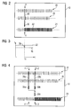
- FIG 3 shows a schematically simplified representation of the frequency f of the second clock frequency 26 and the reference clock frequency 22 over the time t, wherein a clock difference 28 between the second clock frequency 26 and reference clock frequency 22 at the first time t1 is determined.
- the second clock frequency 26 is substantially constant. Alternatively, however, this may also be a change, e.g. by drift, subject.
- FIG. 4 shows a schematically simplified illustration of an alternative embodiment of the method illustrated in FIG. 2, wherein a clock difference 28a, 28b is determined for a first time t1-1 and another time t1-2 and a correction value 30a, 30b is derived therefrom. From these correction values 30a, 30b, a mean correction value 30c is formed and the first clock frequency 24 is applied to the mean correction value 30c.
- Three equidistant times t1-1, t1-2, t1-3 include two likewise equidistant and equally long time intervals ⁇ t1, ⁇ t2. For each time interval ⁇ t1, ⁇ t2, a clock difference 28a, 28b between the second clock frequency 26 and the reference clock frequency 22 is determined and a respective correction value 30a, 30b is derived, with which the first clock frequency 24 is applied.
- FIG. 6 shows a schematically simplified illustration of an electrical device, in particular an automation device 12, with a processing unit 34 and a memory 36 associated memory 34, in which a computer program for performing the method is stored and which is executable by the processing unit 34.
- the invention relates to a method for operating an electrical device, in particular an automation device 12, in which a correction of a first clock frequency 24 based on a second clock frequency 26 and a reference clock frequency 22 takes place. At least one predetermined or predefinable first time t1, a clock difference 28 between the second clock frequency 26 and the reference clock frequency 22 is determined and derived from the clock difference 28, a correction value 30, with which the first clock frequency 24 is applied.
Abstract
Description
Die Erfindung betrifft ein Verfahren zum Betrieb eines elektrischen Gerätes, insbesondere eines Automatisierungsgerätes, bei dem eine Korrektur einer Taktfrequenz erfolgt. Sie betrifft weiter ein elektrisches Gerät, insbesondere ein Automatisierungsgerät, mit Mitteln zur Durchführung des Verfahrens.The invention relates to a method for operating an electrical device, in particular an automation device, in which a correction of a clock frequency. It further relates to an electrical device, in particular an automation device, with means for carrying out the method.
In Automatisierungssystemen ist häufig eine synchrone Bearbeitung bestimmter Steuerungsprogramme oder -routinen erforderlich, wobei die zu deren Ausführung vorgesehenen Automatisierungsgeräte kommunikativ verbunden sind und dazu häufig Hard- oder Softwareelemente zur Erzeugung und/oder Verarbeitung von Taktsignalen umfassen. Solche Taktsignale werden beispielsweise mittels Oszillatoren erzeugt, wobei eine Regelmäßigkeit der Taktsignale dabei von einer Qualität der verwendeten Bauteile sowie von anderen Faktoren, zu welchen auch Alterungsprozesse der Komponenten oder Umweltfaktoren, z.B. Temperatur oder Feuchtigkeit, zählen, beeinflusst wird. Sehr regelmäßige Taktsignale basieren auf Atom-Schwingungen, was bei Atomuhren eine hohe Präzision gewährleistet.In automation systems, synchronous processing of certain control programs or routines is frequently required, with the automation devices provided for their execution being communicatively connected and frequently also comprising hardware or software elements for generating and / or processing clock signals. Such clock signals are generated, for example, by means of oscillators, wherein a regularity of the clock signals depends on a quality of the components used and on other factors, including aging processes of the components or environmental factors, e.g. Temperature or humidity, count, is affected. Very regular clock signals are based on atomic vibrations, which ensures high precision in atomic clocks.
Zum Ausgleich von Laufzeitunterschieden zwischen einer Mehrzahl von Taktsignalen, beispielsweise aufgrund von Drift, erfolgt eine Synchronisation zumindest eines Taktsignals mit einem Referenztaktsignal, welches von einem, ein sehr regelmäßiges Taktsignal erzeugenden Taktfrequenzgeber, wie z.B. einer Atomuhr, erzeugt wird. Dabei erfolgt die Synchronisation der Taktfrequenzen umso genauer, je kürzer ein zur Synchronisation herangezogenes Zeitintervall ist, also je häufiger synchronisiert wird. Dabei muss jedoch ein Kompromiss zwischen der Häufigkeit der Synchronisation und der damit einhergehenden Belastung des Automatisierungssystems durch zusätzlich erforderliche Kommunikation geschlossen werden, weshalb die Zeitintervalle nicht beliebig klein gewählt werden können um die Isochronität der Taktsignale sicherzustellen. Nach einer Synchronisation lässt sich ein Auseinanderlaufen von Taktfrequenz und Referenztaktfrequenz bis zu einer erneuten Synchronisation nicht vermeiden, so dass es insoweit zu Ungenauigkeiten beim Betrieb des Automatisierungssystems kommen kann.To compensate for transit time differences between a plurality of clock signals, for example due to drift, there is a synchronization of at least one clock signal with a reference clock signal which is generated by a, a very regular clock signal generating clock frequency generator, such as an atomic clock. In this case, the synchronization of the clock frequencies is more accurate, the shorter a time interval used for the synchronization, that is, the more frequently synchronized. However, a compromise must be made between the frequency of synchronization and the associated load on the automation system by additionally required communication, Therefore, the time intervals can not be chosen arbitrarily small to ensure the isochronicity of the clock signals. After synchronization, it is not possible to avoid divergence from clock frequency and reference clock frequency until a new synchronization, so that in this respect inaccuracies in the operation of the automation system can occur.
Eine Aufgabe der Erfindung besteht darin, ein Verfahren anzugeben, bei dem die oben genannten Nachteile vermieden oder zumindest hinsichtlich ihrer Auswirkungen reduziert werden.An object of the invention is to provide a method in which the abovementioned disadvantages are avoided or at least reduced in terms of their effects.
Diese Aufgabe wird gelöst durch ein Verfahren zum Betrieb eines elektrischen Gerätes, insbesondere eines Automatisierungsgerätes, bei welchem eine Korrektur einer ersten Taktfrequenz anhand einer zweiten Taktfrequenz sowie einer Referenztaktfrequenz erfolgt. Dabei wird zu mindestens einem vorgegebenen oder vorgebbaren ersten Zeitpunkt eine Taktdifferenz zwischen der zweiten Taktfrequenz und der Referenztaktfrequenz bestimmt. Aus dieser Taktdifferenz wird ein Korrekturwert abgeleitet, mit dem die erste Taktfrequenz beaufschlagt wird. Es erfolgt also quasi eine Synchronisation der ersten Taktfrequenz mit der Referenztaktfrequenz auf Basis der Differenz zwischen Referenztaktfrequenz und zweiter Taktfrequenz.This object is achieved by a method for operating an electrical device, in particular an automation device, in which a correction of a first clock frequency based on a second clock frequency and a reference clock frequency. In this case, a clock difference between the second clock frequency and the reference clock frequency is determined at least one predetermined or predefinable first time. From this clock difference, a correction value is derived, with which the first clock frequency is applied. Thus, there is virtually a synchronization of the first clock frequency with the reference clock frequency on the basis of the difference between the reference clock frequency and the second clock frequency.
Weiterhin wird diese Aufgabe gelöst durch ein Computerprogramm mit Programmcodeanweisungen zur Implementierung des Verfahrens, wenn das Computerprogramm auf einem Computer ausgeführt wird, sowie durch ein Computerprogrammprodukt, insbesondere Speichermedium, mit dem durch einen Computer ausführbaren Computerprogramm.Furthermore, this object is achieved by a computer program with program code instructions for implementing the method when the computer program is executed on a computer, and by a computer program product, in particular storage medium, with the computer-executable computer program.
Zudem wird diese Aufgabe durch ein elektrisches Gerät, insbesondere Automatisierungsgerät, mit Mitteln zur Durchführung des Verfahrens, insbesondere einer Verarbeitungseinheit und einem der Verarbeitungseinheit zugeordneten Speicher, gelöst.In addition, this object is achieved by an electrical device, in particular an automation device, having means for carrying out the method, in particular a processing unit and a memory assigned to the processing unit.
In dem Speicher ist dabei das durch die Verarbeitungseinheit ausführbare Computerprogramm gespeichert.In this case, the computer program executable by the processing unit is stored in the memory.
Durch dieses Verfahren wird eine regelmäßige und mit der Referenztaktfrequenz im Wesentlichen synchrone erste Taktfrequenz bei einer geringeren Häufigkeit der Synchronisation erzeugt, mittels welcher beispielsweise eine Drift kompensiert wird. Aus dieser geringeren Häufigkeit ergibt sich eine Minimierung der zusätzlichen, zur Synchronisation erforderlichen Kommunikation in dem Automatisierungssystem. Wenn die Synchronisierung permanent und automatisch stattfindet, ergibt sich eine automatische Kalibrierung ohne dass ein Anstoß von außen, z.B. eine Aktivität des Anwenders, erforderlich wäre, was zu einer Erhöhung eines Bedienkomforts des Automatisierungssystems führt.By this method, a regular and with the reference clock frequency substantially synchronous first clock frequency is generated at a lower frequency of synchronization, by means of which, for example, a drift is compensated. This lower frequency results in a minimization of the additional communication required for synchronization in the automation system. If the synchronization takes place permanently and automatically, an automatic calibration results without any external impact, e.g. an activity of the user, would be required, resulting in an increase in ease of use of the automation system.
Zweckmäßige Weiterbildungen des Verfahrens zum Betrieb eines elektrischen Gerätes sind Gegenstand der auf Anspruch 1 rückbezogenen Unteransprüche. In Unteransprüchen verwendete Rückbeziehungen weisen auf die weitere Ausbildung des Gegenstandes des Hauptanspruches durch die Merkmale des jeweiligen Unteranspruches hin; sie sind nicht als ein Verzicht auf die Erzielung eines selbständigen, gegenständlichen Schutzes für die Merkmalskombinationen der rückbezogenen Unteransprüche zu verstehen. Des Weiteren ist im Hinblick auf eine Auslegung der Ansprüche bei einer näheren Konkretisierung eines Merkmals in einem nachgeordneten Anspruch davon auszugehen, dass eine derartige Beschränkung in den jeweils vorangehenden Ansprüchen nicht vorhanden ist.Advantageous developments of the method for operating an electrical device are the subject of the dependent claims on
Bevorzugt ist vorgesehen, dass zu dem oder jedem vorgegebenen oder vorgebbaren ersten Zeitpunkt eine Synchronisation der zweiten Taktfrequenz mit der Referenztaktfrequenz erfolgt. Dabei wird im Zusammenhang mit der Synchronisation der zweiten Taktfrequenz mit der Referenztaktfrequenz die Taktdifferenz zwischen der zweiten Taktfrequenz und der Referenztaktfrequenz bestimmt. Hierbei meint "im Zusammenhang" vor oder während, jedoch vor Abschluss der Synchronisation.It is preferably provided that the second clock frequency is synchronized with the reference clock frequency at the or each predetermined or predefinable first time. In this case, the clock difference between the second clock frequency and the reference clock frequency is determined in connection with the synchronization of the second clock frequency with the reference clock frequency. Hereby means "in context" before or during, but before completion of synchronization.
Eine geringfügige Ungleichheit von Taktfrequenzen und damit eine Differenz, z.B. zwischen der zweiten Taktfrequenz und der Referenztaktfrequenz, ergibt sich beispielsweise durch fertigungsbedingte Toleranzen von zur Taktfrequenzerzeugung vorgesehenen Bauelementen, durch Alterungs- oder Verschlei-ßerscheinungen des Taktfrequenzgebers oder durch eine beispielsweise temperaturbedingte Drift der ersten und zweiten Taktfrequenz. Eine solche Differenz kann beispielsweise als eine Differenz der zweiten Taktfrequenz und der Referenztaktfrequenz zu einem beliebigen Zeitpunkt, also eine relative Differenz, oder als eine Gesamtheit für einen Zeitraum nach der Synchronisation ermittelter Differenzen, also eine absolute Differenz, angegeben werden. Eine Synchronisation der zweiten Taktfrequenz mit der Referenztaktfrequenz setzt die absolute Differenz der Taktfrequenzen zurück, erleichtert somit die Ermittlung des Korrekturwertes, mit welchem die erste Taktfrequenz beaufschlagt wird und verringert einen möglichen Fehler bei der Ermittlung des Korrekturwertes welcher sich aufgrund von sehr großen Werten der Differenz ergeben würde. Wenn die Taktdifferenz im Zusammenhang mit der Synchronisation, also zeitnah zu einem Synchronisationszeitpunkt, ermittelt wird, dann hat die Taktdifferenz zwischen zweiter Taktfrequenz und Referenztaktfrequenz einen für dieses Verfahren maximal möglichen Wert, wodurch ein potentieller Fehler bei der Bestimmung der Taktdifferenz und im Folgenden des Korrekturwertes vermindert wird.A slight inequality of clock frequencies and thus a difference, e.g. between the second clock frequency and the reference clock frequency, for example, results from production-related tolerances of the clock frequency generation components provided by aging or wear phenomena of the clock frequency or by a temperature-related drift, for example, the first and second clock frequency. Such a difference can be indicated, for example, as a difference of the second clock frequency and the reference clock frequency at any desired time, that is to say a relative difference, or as a totality for a period after the synchronization of determined differences, ie an absolute difference. A synchronization of the second clock frequency with the reference clock frequency resets the absolute difference of the clock frequencies, thus facilitating the determination of the correction value with which the first clock frequency is applied and reduces a possible error in the determination of the correction value which results from very large values of the difference would. If the clock difference in connection with the synchronization, ie, timely to a synchronization time is determined, then the clock difference between the second clock frequency and reference clock frequency has a maximum possible value for this method, thereby reducing a potential error in the determination of the clock difference and subsequently the correction value becomes.
Zusätzlich oder alternativ erfolgt zu mindestens einem vorgegebenen oder vorgebbaren zweiten Zeitpunkt eine Synchronisation der ersten und der zweiten Taktfrequenz mit der Referenztaktfrequenz. Hieraus ergibt sich eine Vereinfachung der Beaufschlagung der ersten Taktfrequenz mit dem aus der Taktdifferenz zwischen der zweiten Taktfrequenz und der Referenztaktfrequenz mathematisch oder logisch abgeleiteten Korrekturwert sowie ein geringerer potentieller Fehler, da es zu keiner additiven oder multiplikativen Vergrößerung des Fehlers kommt.Additionally or alternatively, a synchronization of the first and the second clock frequency with the reference clock frequency takes place at least one predetermined or predefinable second time. This results in a simplification of the application of the first clock frequency with the mathematically or logically derived correction value from the clock difference between the second clock frequency and the reference clock frequency as well as a lesser potential error since there is no additive or multiplicative increase in the error.
Wird jeweils zumindest ein Korrekturwert für den ersten und mindestens einen weiteren Zeitpunkt ermittelt, zumindest ein mittlerer Korrekturwert aus den ermittelten Korrekturwerten gebildet und die erste Taktfrequenz mit dem mittleren Korrekturwert beaufschlagt, so ergibt sich eine Verbesserung des mittleren Korrekturwertes mit jedem zu dessen Ermittlung herangezogenen Korrekturwert. Es wird also eine Verbesserung des Korrekturwertes erreicht und mit steigender Anzahl gemittelter Korrekturwerte wird eine Verbesserung der Synchronität von erster Taktfrequenz und Referenztaktfrequenz und somit eine Qualitätsverbesserung erreicht.If in each case at least one correction value is determined for the first and at least one further time, at least one mean correction value is formed from the determined correction values and the first clock frequency is applied to the mean correction value, the average correction value is improved with each correction value used for its determination. Thus, an improvement in the correction value is achieved, and as the number of averaged correction values increases, an improvement in the synchronism of the first clock frequency and reference clock frequency and thus an improvement in quality is achieved.
Besonders bevorzugt sind ein erster Zeitpunkt und mindestens zwei weitere Zeitpunkte auf einer Zeitachse äquidistant zueinander angeordnet, wobei jeweils zwei aufeinander folgende Zeitpunkte ein Zeitintervall einschließen. Der Korrekturwert wird jeweils für ein solches Zeitintervall oder mindestens einen Teil davon ermittelt. Somit wird die Wahrscheinlichkeit die Bestimmung der Taktdifferenz gleichzeitig zu einem Auftreten mindestens eines die Takterzeugung beeinflussenden äußeren Ereignisses, z.B. kurzfristigen Temperaturschwankungen, durchzuführen, verringert. Die Taktdifferenz kann dabei über das gesamte Zeitintervall oder zumindest einen Teil des Zeitintervalls gemittelt oder integriert werden. Zusätzlich oder alternativ kann vorgesehen sein, dass für mehrere Zeitintervalle Taktdifferenzen und/oder Korrekturwerte gemittelt werden oder über mehrere Zeitintervalle oder Teile davon integriert werden. Durch das Mitteln und/oder das Integrieren der Taktdifferenz und/oder des Korrekturwertes wird deren qualitative Verbesserung erreicht, da beispielsweise eine Auswirkung kurzzeitiger äußerer Einflüsse wie einer Erschütterung, kurzzeitiger Erwärmung oder eines kurzfristig einwirkenden elektrischen Feldes oder mathematischer Fehler minimiert wird.Particularly preferably, a first point in time and at least two further points in time are arranged equidistant from each other on a time axis, wherein in each case two successive points in time include a time interval. The correction value is determined in each case for such a time interval or at least a part thereof. Thus, the likelihood of determining the clock difference simultaneously with an occurrence of at least one external event affecting the clock generation, e.g. short-term temperature fluctuations, perform reduced. The clock difference can be averaged or integrated over the entire time interval or at least part of the time interval. Additionally or alternatively, it can be provided that for several time intervals, clock differences and / or correction values are averaged or integrated over a plurality of time intervals or parts thereof. By averaging and / or integrating the clock difference and / or the correction value whose qualitative improvement is achieved because, for example, an effect of brief external influences such as vibration, short-term heating or a short-term acting electric field or mathematical errors is minimized.
Zudem kann vorgesehen sein, dass entweder die Taktdifferenz oder der aus dieser abgeleitete Korrekturwert auf eine Anzahl von Takten der Referenztaktfrequenz bezogen wird, über welche entweder die Taktdifferenz oder der Korrekturwert integriert oder gemittelt wurde. Wurde die Taktdifferenz oder der Korrekturwert zu einem ersten Zeitpunkt bestimmt bzw. ermittelt und ist dieser Zeitpunkt einem vorangegangenen Zeitintervall zugeordnet, so wird die Taktdifferenz oder der Korrekturwert auf die Anzahl von Referenztaktfrequenz-Takten des Zeitintervalls bezogen. Hierdurch ergibt sich ein Korrekturwert pro Takt zur Beaufschlagung der ersten Taktfrequenz.In addition, it can be provided that either the clock difference or the correction value derived therefrom is related to a number of clocks of the reference clock frequency, via which either the clock difference or the correction value has been integrated or averaged. If the clock difference or the correction value has been determined or determined at a first time and this time is assigned to a preceding time interval, then the clock difference or the correction value is related to the number of reference clock frequency clocks of the time interval. This results in a correction value per clock for applying the first clock frequency.
Bevorzugt sind die erste und die zweite Taktfrequenz so gewählt, dass eine Differenz dieser Taktfrequenzen im Wesentlichen gleich bleibt. Hierdurch wird sichergestellt, dass eine Abweichung zwischen der ersten Taktfrequenz und der zweiten Taktfrequenz konstant bleibt, also ein Faktor - ein Abweichungsfaktor-, um welchen sich beide Taktfrequenzen unterscheiden, konstant ist. Somit wird gewährleistet, dass eine Beaufschlagung der ersten Taktfrequenz mit dem Korrekturwert, gegebenenfalls unter Einbeziehung des Abweichungsfaktors, zu einer Annäherung der ersten Taktfrequenz an die Referenztaktfrequenz, also zu einer besseren Annäherung der ersten Taktfrequenz an die Referenztaktfrequenz, führt. Besonders bevorzugt sind die erste Taktfrequenz und die zweite Taktfrequenz im Wesentlichen gleich, was beispielsweise durch Verwendung eines Taktfrequenzgebers zur Erzeugung der ersten und der zweiten Taktfrequenz oder eine Verwendung von im Wesentlichen gleichen Taktfrequenzgebern erreicht wird, wobei "im Wesentlichen gleich" hier Taktfrequenzgeber meint, welche eine im Wesentlichen gleiche Taktfrequenz erzeugen und deren Taktfrequenzen sich beispielsweise bezüglich Drift im Wesentlichen gleich verhalten.Preferably, the first and the second clock frequency are selected so that a difference of these clock frequencies remains substantially the same. This ensures that a deviation between the first clock frequency and the second clock frequency remains constant, ie a factor - a deviation factor - by which both clock frequencies differ is constant. This ensures that an admission of the first clock frequency with the correction value, possibly taking into account the deviation factor, leads to an approximation of the first clock frequency to the reference clock frequency, ie to a better approximation of the first clock frequency to the reference clock frequency. Particularly preferably, the first clock frequency and the second clock frequency are substantially the same, which is achieved, for example, by using a clock frequency generator for generating the first and the second clock frequency or a use of substantially the same clock frequency, where "substantially equal" means here Clock frequency, which generate a substantially same clock frequency and the clock frequencies behave substantially the same, for example, with respect to drift.
Die mit der Anmeldung eingereichten Patentansprüche sind Formulierungsvorschläge ohne Präjudiz für die Erzielung weitergehenden Patentschutzes. Die Anmelderin behält sich vor, noch weitere, bisher nur in der Beschreibung und/oder Zeichnung offenbarte Merkmalskombination zu beanspruchen.The claims filed with the application are formulation proposals without prejudice to the achievement of further patent protection. The Applicant reserves the right to claim further, previously only disclosed in the description and / or drawing combination of features.
Das oder jedes Ausführungsbeispiel ist nicht als Einschränkung der Erfindung zu verstehen. Vielmehr sind im Rahmen der vorliegenden Offenbarung zahlreiche Abänderungen und Modifikationen möglich, insbesondere solche Varianten, Elemente und Kombinationen, die zum Beispiel durch Kombination oder Abwandlung von einzelnen in Verbindung mit den im allgemeinen oder speziellen Beschreibungsteil beschriebenen sowie in den Ansprüchen und/oder der Zeichnung enthaltenen Merkmalen bzw. Elementen oder Verfahrensschritten für den Fachmann im Hinblick auf die Lösung der Aufgabe entnehmbar sind und durch kombinierbare Merkmale zu einem neuen Gegenstand oder zu neuen Verfahrensschritten bzw. Verfahrensschrittfolgen führen.The or each embodiment is not to be understood as limiting the invention. Rather, numerous changes and modifications are possible within the scope of the present disclosure, in particular those variants, elements and combinations, for example, by combination or modification of individual described in conjunction with the general or specific description part and in the claims and / or the drawings Characteristics or elements or method steps for the expert in terms of solving the problem can be removed and lead by combinable features to a new subject or to new process steps or procedural steps.
Nachfolgend wird ein Ausführungsbeispiel der Erfindung anhand der Zeichnung näher erläutert. Einander entsprechende Gegenstände oder Elemente sind in allen Figuren mit den gleichen Bezugszeichen versehen.An embodiment of the invention will be explained in more detail with reference to the drawing. Corresponding objects or elements are provided in all figures with the same reference numerals.
Darin zeigen
- FIG 1
- eine schematisch vereinfachte Darstellung eines Automatisierungssystems mit einem ersten elektrischen Gerät, insbesondere einem ersten Automatisierungsgerät, zur Durchführung eines Verfahrens zur Korrektur einer Taktfrequenz,
- FIG 2
- eine schematisch vereinfachte Darstellung des Verfahrens,
- FIG 3
- eine schematisch vereinfachte Darstellung der Frequenz einer zweiten Taktfrequenz und einer Referenztaktfrequenz über der Zeit,
- FIG 4
- eine schematisch vereinfachte Darstellung einer alternativen Ausführungsform des in FIG 2 dargestellten Verfahrens,
- FIG 5
- eine schematisch vereinfachte Darstellung eines besonders bevorzugten Ausführungsbeispiels des in FIG 4 dargestellten Verfahrens und
- FIG 6
- eine schematisch vereinfachte Darstellung eines elektrischen Gerätes zur Durchführung des Verfahrens.
- FIG. 1
- a schematically simplified representation of an automation system with a first electrical device, in particular a first automation device, for performing a method for correcting a clock frequency,
- FIG. 2
- a schematically simplified representation of the method,
- FIG. 3
- a schematically simplified representation of the frequency of a second clock frequency and a reference clock frequency over time,
- FIG. 4
- 2 is a simplified schematic representation of an alternative embodiment of the method illustrated in FIG. 2,
- FIG. 5
- a schematically simplified representation of a particularly preferred embodiment of the method shown in FIG 4 and
- FIG. 6
- a schematically simplified representation of an electrical device for carrying out the method.
FIG 1 zeigt eine schematisch vereinfachte Darstellung eines Automatisierungssystems 10 mit einem ersten elektrischen Gerät, insbesondere einem ersten Automatisierungsgerät 12, zur Durchführung eines Verfahrens zur Korrektur einer Taktfrequenz und einem zweiten Automatisierungsgerät 14 mit einem Referenzfrequenzgeber 16. Alternativ kann der Referenzfrequenzgeber 16 entfernt von dem Automatisierungssystem 10 angeordnet sein. Dem ersten Automatisierungsgerät 12 ist ein erster Taktfrequenzgeber 18 und ein zweiter Taktfrequenzgeber 20 zugeordnet, wobei der Referenztaktfrequenzgeber 16 eine Referenztaktfrequenz 22, der erste Taktfrequenzgeber 18 eine erste Taktfrequenz 24 und der zweite Taktfrequenzgeber 20 eine zweite Taktfrequenz 26 erzeugt. Alternativ kann der zweite Taktfrequenzgeber 20 dem zweiten Automatisierungsgerät 14 oder einem weiteren Automatisierungsgerät zugeordnet sein.1 shows a schematically simplified representation of an
FIG 2 zeigt eine schematisch vereinfachte Darstellung des Verfahrens, wobei bei einem Betrieb des Automatisierungssystems 10 gemäß FIG 1 eine Korrektur der ersten Taktfrequenz 24 anhand der zweiten Taktfrequenz 26 sowie der Referenztaktfrequenz 22 erfolgt. Zu einem ersten Zeitpunkt t1 wird eine Taktdifferenz 28 zwischen der zweiten Taktfrequenz 26 und der Referenztaktfrequenz 22 ermittelt und aus der Taktdifferenz 28 ein Korrekturwert 30 abgeleitet, mit dem die erste Taktfrequenz 24 beaufschlagt wird, z.B. indem der Korrekturwert 30 zur ersten Taktfrequenz 24 addiert wird. Dabei wird jeder Takt 32 der ersten Taktfrequenz 24 mit dem Korrekturwert 30 beaufschlagt. Zudem kann im Zusammenhang mit der Ermittlung der Taktdifferenz 28, also zeitnah nach der Bestimmung der Taktdifferenz 28, eine Synchronisation der zweiten Taktfrequenz 26 mit der Referenztaktfrequenz 22, also eine Anpassung an die Referenztaktfrequenz 22, oder eine Synchronisation der zweiten Taktfrequenz 26 und der ersten Taktfrequenz 24 mit der Referenztaktfrequenz 22 erfolgen.FIG. 2 shows a schematically simplified representation of the method, wherein during operation of the
FIG 3 zeigt eine schematisch vereinfachte Darstellung der Frequenz f der zweiten Taktfrequenz 26 und der Referenztaktfrequenz 22 über der Zeit t, wobei eine Taktdifferenz 28 zwischen zweiter Taktfrequenz 26 und Referenztaktfrequenz 22 zum ersten Zeitpunkt t1 bestimmt wird. Die zweite Taktfrequenz 26 ist dabei im Wesentlichen konstant. Alternativ kann diese jedoch auch einer Änderung, z.B. durch Drift, unterliegen.3 shows a schematically simplified representation of the frequency f of the
FIG 4 zeigt eine schematisch vereinfachte Darstellung einer alternativen Ausführungsform des in FIG 2 dargestellten Verfahrens, wobei für einen ersten Zeitpunkt t1-1 und einen weiteren Zeitpunkt t1-2 jeweils eine Taktdifferenz 28a, 28b ermittelt und daraus jeweils ein Korrekturwert 30a, 30b abgeleitet wird. Aus diesen Korrekturwerten 30a, 30b wird ein mittlerer Korrekturwert 30c gebildet und die erste Taktfrequenz 24 mit dem mittleren Korrekturwert 30c beaufschlagt.FIG. 4 shows a schematically simplified illustration of an alternative embodiment of the method illustrated in FIG. 2, wherein a
FIG 5 zeigt eine schematisch vereinfachte Darstellung eines besonders bevorzugten Ausführungsbeispiels des in FIG 4 dargestellten Verfahrens. Drei äquidistante Zeitpunkte t1-1, t1-2, t1-3 schließen zwei ebenfalls äquidistante sowie gleich lange Zeitintervalle Δt1, Δt2 ein. Für jedes Zeitintervall Δt1, Δt2 wird eine Taktdifferenz 28a, 28b zwischen der zweiten Taktfrequenz 26 und der Referenztaktfrequenz 22 ermittelt und jeweils ein Korrekturwert 30a, 30b abgeleitet, mit welchem die erste Taktfrequenz 24 beaufschlagt wird.5 shows a schematically simplified representation of a particularly preferred embodiment of the method shown in FIG. Three equidistant times t1-1, t1-2, t1-3 include two likewise equidistant and equally long time intervals Δt1, Δt2. For each time interval Δt1, Δt2, a
FIG 6 zeigt eine schematisch vereinfachte Darstellung eines elektrischen Gerätes, insbesondere eines Automatisierungsgerätes 12, mit einer Verarbeitungseinheit 34 und einem der Verarbeitungseinheit 34 zugeordneten Speicher 36, in dem ein Computerprogramm zur Durchführung des Verfahrens gespeichert ist und das durch die Verarbeitungseinheit 34 ausführbar ist.6 shows a schematically simplified illustration of an electrical device, in particular an
Damit lässt sich die Erfindung kurz wie folgt darstellen: Die Erfindung betrifft ein Verfahren zum Betrieb eines elektrischen Gerätes, insbesondere eines Automatisierungsgerätes 12, bei dem eine Korrektur einer ersten Taktfrequenz 24 anhand einer zweiten Taktfrequenz 26 sowie einer Referenztaktfrequenz 22 erfolgt. Zu mindestens einem vorgegebenen oder vorgebbaren ersten Zeitpunkt t1 wird eine Taktdifferenz 28 zwischen der zweiten Taktfrequenz 26 und der Referenztaktfrequenz 22 bestimmt und aus der Taktdifferenz 28 ein Korrekturwert 30 abgeleitet, mit dem die erste Taktfrequenz 24 beaufschlagt wird.The invention relates to a method for operating an electrical device, in particular an
Claims (10)
Priority Applications (2)
| Application Number | Priority Date | Filing Date | Title |
|---|---|---|---|
| DE200650004321 DE502006004321D1 (en) | 2006-09-21 | 2006-09-21 | Method for clock synchronization of an electrical device to a reference clock and electrical device |
| EP20060019806 EP1903681B1 (en) | 2006-09-21 | 2006-09-21 | Method for synchronising the clock of an electrical apparatus with a reference clock and electrical apparatus |
Applications Claiming Priority (1)
| Application Number | Priority Date | Filing Date | Title |
|---|---|---|---|
| EP20060019806 EP1903681B1 (en) | 2006-09-21 | 2006-09-21 | Method for synchronising the clock of an electrical apparatus with a reference clock and electrical apparatus |
Publications (2)
| Publication Number | Publication Date |
|---|---|
| EP1903681A1 true EP1903681A1 (en) | 2008-03-26 |
| EP1903681B1 EP1903681B1 (en) | 2009-07-22 |
Family
ID=37714629
Family Applications (1)
| Application Number | Title | Priority Date | Filing Date |
|---|---|---|---|
| EP20060019806 Active EP1903681B1 (en) | 2006-09-21 | 2006-09-21 | Method for synchronising the clock of an electrical apparatus with a reference clock and electrical apparatus |
Country Status (2)
| Country | Link |
|---|---|
| EP (1) | EP1903681B1 (en) |
| DE (1) | DE502006004321D1 (en) |
Cited By (1)
| Publication number | Priority date | Publication date | Assignee | Title |
|---|---|---|---|---|
| DE102022108316A1 (en) | 2022-04-06 | 2023-10-12 | Endress+Hauser SE+Co. KG | Method for checking at least a first clock generator of a first field device in a process measurement system |
Citations (6)
| Publication number | Priority date | Publication date | Assignee | Title |
|---|---|---|---|---|
| US6052034A (en) * | 1998-06-24 | 2000-04-18 | Industrial Technology Research Institute | Method and apparatus for all digital holdover circuit |
| US6166606A (en) * | 1999-02-10 | 2000-12-26 | Zilog, Inc. | Phase and frequency locked clock generator |
| DE10022486C1 (en) | 2000-05-09 | 2002-01-17 | Infineon Technologies Ag | Digital phase locked loop |
| US20030197537A1 (en) * | 2002-04-19 | 2003-10-23 | Martin Saint-Laurent | Clock distribution network using feedback for skew compensation and jitter filtering |
| WO2004034631A1 (en) * | 2002-10-10 | 2004-04-22 | Infineon Technologies Ag | Clock signal extraction device and method for extracting a clock signal from a data signal |
| EP1557951A1 (en) * | 2004-01-21 | 2005-07-27 | Telefonaktiebolaget LM Ericsson (publ) | Frequency generator with multiple voltage-controlled oscillators |
-
2006
- 2006-09-21 EP EP20060019806 patent/EP1903681B1/en active Active
- 2006-09-21 DE DE200650004321 patent/DE502006004321D1/en active Active
Patent Citations (6)
| Publication number | Priority date | Publication date | Assignee | Title |
|---|---|---|---|---|
| US6052034A (en) * | 1998-06-24 | 2000-04-18 | Industrial Technology Research Institute | Method and apparatus for all digital holdover circuit |
| US6166606A (en) * | 1999-02-10 | 2000-12-26 | Zilog, Inc. | Phase and frequency locked clock generator |
| DE10022486C1 (en) | 2000-05-09 | 2002-01-17 | Infineon Technologies Ag | Digital phase locked loop |
| US20030197537A1 (en) * | 2002-04-19 | 2003-10-23 | Martin Saint-Laurent | Clock distribution network using feedback for skew compensation and jitter filtering |
| WO2004034631A1 (en) * | 2002-10-10 | 2004-04-22 | Infineon Technologies Ag | Clock signal extraction device and method for extracting a clock signal from a data signal |
| EP1557951A1 (en) * | 2004-01-21 | 2005-07-27 | Telefonaktiebolaget LM Ericsson (publ) | Frequency generator with multiple voltage-controlled oscillators |
Cited By (1)
| Publication number | Priority date | Publication date | Assignee | Title |
|---|---|---|---|---|
| DE102022108316A1 (en) | 2022-04-06 | 2023-10-12 | Endress+Hauser SE+Co. KG | Method for checking at least a first clock generator of a first field device in a process measurement system |
Also Published As
| Publication number | Publication date |
|---|---|
| EP1903681B1 (en) | 2009-07-22 |
| DE502006004321D1 (en) | 2009-09-03 |
Similar Documents
| Publication | Publication Date | Title |
|---|---|---|
| DE10291119B4 (en) | A method and apparatus for synchronizing the cycle time of multiple buses, wherein at least one of the buses is a TTCAN bus, and a corresponding bus system | |
| DE102017006876B4 (en) | Server, procedure, program, recording medium and system for maintaining temporal accuracy | |
| EP3317742A2 (en) | Device for generating a plurality of clock signals or high-frequency signals | |
| EP1639758B1 (en) | Method and device for the exchange of data via a bus system | |
| EP2645200A1 (en) | Method and data processing assembly for producing a timestamp | |
| DE19722114C2 (en) | Clock signal providing device and method | |
| DE10125533B4 (en) | Method for operating a position-measuring device and position-measuring device and evaluation unit for carrying out the method | |
| EP2299614B1 (en) | Device and method for time synchronisation in a communication network | |
| EP1903681B1 (en) | Method for synchronising the clock of an electrical apparatus with a reference clock and electrical apparatus | |
| EP3438773A1 (en) | Processing of workpieces with model-supported error compensation | |
| DE19828967C2 (en) | Method for measuring and compensating an inaccurate clock signal | |
| WO2002028003A2 (en) | Method for synchronizing a plurality of bus systems and corresponding hierarchical multiple bus system | |
| EP3783317B1 (en) | Sensor device with synchronisation of a sensor signal with an interrogation signal | |
| DE4442306C2 (en) | Method and arrangement for determining phase changes in a reference input signal of a phase locked loop | |
| DE102008019287A1 (en) | A method for automatically generating a time scheme for communicating distributed processes of a digital network | |
| DE2835200B2 (en) | Method and circuit for setting an electronic digital display of a target duration | |
| EP2476029B1 (en) | Time synchronization in automation devices | |
| EP2928110A1 (en) | Method for synchronising an isochronous system with a higher level clock system | |
| DE102014108541B4 (en) | Drive system with increased accuracy in setpoint signal transmission (method and system) | |
| EP4327178A1 (en) | Device and method for monitoring two time bases of two communication devices with the aid of a computer | |
| DE2806924C3 (en) | Procedure for moving the pulses forward or back in a pulse train | |
| EP3767485A1 (en) | Method and system for exchanging timestamped data | |
| DE102019110150A1 (en) | Method for simple drift compensation of local timepieces and device therefor | |
| DE2408143A1 (en) | Synchronisation method for counters - counters are in two independently synchronised groups | |
| WO2009030370A1 (en) | Device and method for performing server software updates in a distributed computer system having at least two servers |
Legal Events
| Date | Code | Title | Description |
|---|---|---|---|
| PUAI | Public reference made under article 153(3) epc to a published international application that has entered the european phase |
Free format text: ORIGINAL CODE: 0009012 |
|
| AK | Designated contracting states |
Kind code of ref document: A1 Designated state(s): AT BE BG CH CY CZ DE DK EE ES FI FR GB GR HU IE IS IT LI LT LU LV MC NL PL PT RO SE SI SK TR |
|
| AX | Request for extension of the european patent |
Extension state: AL BA HR MK YU |
|
| 17P | Request for examination filed |
Effective date: 20080411 |
|
| 17Q | First examination report despatched |
Effective date: 20080520 |
|
| AKX | Designation fees paid |
Designated state(s): DE FR GB IT |
|
| GRAP | Despatch of communication of intention to grant a patent |
Free format text: ORIGINAL CODE: EPIDOSNIGR1 |
|
| GRAS | Grant fee paid |
Free format text: ORIGINAL CODE: EPIDOSNIGR3 |
|
| GRAA | (expected) grant |
Free format text: ORIGINAL CODE: 0009210 |
|
| AK | Designated contracting states |
Kind code of ref document: B1 Designated state(s): DE FR GB IT |
|
| REG | Reference to a national code |
Ref country code: GB Ref legal event code: FG4D Free format text: NOT ENGLISH |
|
| REF | Corresponds to: |
Ref document number: 502006004321 Country of ref document: DE Date of ref document: 20090903 Kind code of ref document: P |
|
| PLBE | No opposition filed within time limit |
Free format text: ORIGINAL CODE: 0009261 |
|
| STAA | Information on the status of an ep patent application or granted ep patent |
Free format text: STATUS: NO OPPOSITION FILED WITHIN TIME LIMIT |
|
| 26N | No opposition filed |
Effective date: 20100423 |
|
| REG | Reference to a national code |
Ref country code: FR Ref legal event code: PLFP Year of fee payment: 11 |
|
| REG | Reference to a national code |
Ref country code: FR Ref legal event code: PLFP Year of fee payment: 12 |
|
| REG | Reference to a national code |
Ref country code: FR Ref legal event code: PLFP Year of fee payment: 13 |
|
| PGFP | Annual fee paid to national office [announced via postgrant information from national office to epo] |
Ref country code: IT Payment date: 20230920 Year of fee payment: 18 Ref country code: GB Payment date: 20230904 Year of fee payment: 18 |
|
| PGFP | Annual fee paid to national office [announced via postgrant information from national office to epo] |
Ref country code: FR Payment date: 20230905 Year of fee payment: 18 Ref country code: DE Payment date: 20230808 Year of fee payment: 18 |