EP2928110A1 - Method for synchronising an isochronous system with a higher level clock system - Google Patents
Method for synchronising an isochronous system with a higher level clock system Download PDFInfo
- Publication number
- EP2928110A1 EP2928110A1 EP14163047.5A EP14163047A EP2928110A1 EP 2928110 A1 EP2928110 A1 EP 2928110A1 EP 14163047 A EP14163047 A EP 14163047A EP 2928110 A1 EP2928110 A1 EP 2928110A1
- Authority
- EP
- European Patent Office
- Prior art keywords
- clock
- clock system
- components
- component
- basic
- Prior art date
- Legal status (The legal status is an assumption and is not a legal conclusion. Google has not performed a legal analysis and makes no representation as to the accuracy of the status listed.)
- Granted
Links
- 238000000034 method Methods 0.000 title claims abstract description 35
- 230000001360 synchronised effect Effects 0.000 claims abstract description 16
- 238000004891 communication Methods 0.000 claims description 33
- 238000004590 computer program Methods 0.000 claims description 11
- 238000004519 manufacturing process Methods 0.000 claims description 11
- 238000012545 processing Methods 0.000 claims description 6
- 238000003860 storage Methods 0.000 claims description 2
- 230000010363 phase shift Effects 0.000 description 11
- 230000008569 process Effects 0.000 description 7
- 230000005540 biological transmission Effects 0.000 description 6
- 230000006978 adaptation Effects 0.000 description 4
- 238000004364 calculation method Methods 0.000 description 3
- 230000008859 change Effects 0.000 description 3
- 230000001419 dependent effect Effects 0.000 description 3
- 230000000694 effects Effects 0.000 description 3
- 238000009826 distribution Methods 0.000 description 2
- 238000012986 modification Methods 0.000 description 2
- 230000004048 modification Effects 0.000 description 2
- 241001136792 Alle Species 0.000 description 1
- 238000013459 approach Methods 0.000 description 1
- 230000008901 benefit Effects 0.000 description 1
- 238000011161 development Methods 0.000 description 1
- 230000006870 function Effects 0.000 description 1
- 230000001629 suppression Effects 0.000 description 1
- 238000012546 transfer Methods 0.000 description 1
Images

Classifications
-
- H—ELECTRICITY
- H04—ELECTRIC COMMUNICATION TECHNIQUE
- H04L—TRANSMISSION OF DIGITAL INFORMATION, e.g. TELEGRAPHIC COMMUNICATION
- H04L7/00—Arrangements for synchronising receiver with transmitter
- H04L7/0004—Initialisation of the receiver
-
- H—ELECTRICITY
- H04—ELECTRIC COMMUNICATION TECHNIQUE
- H04L—TRANSMISSION OF DIGITAL INFORMATION, e.g. TELEGRAPHIC COMMUNICATION
- H04L7/00—Arrangements for synchronising receiver with transmitter
- H04L7/04—Speed or phase control by synchronisation signals
-
- G—PHYSICS
- G05—CONTROLLING; REGULATING
- G05B—CONTROL OR REGULATING SYSTEMS IN GENERAL; FUNCTIONAL ELEMENTS OF SUCH SYSTEMS; MONITORING OR TESTING ARRANGEMENTS FOR SUCH SYSTEMS OR ELEMENTS
- G05B19/00—Programme-control systems
- G05B19/02—Programme-control systems electric
- G05B19/04—Programme control other than numerical control, i.e. in sequence controllers or logic controllers
- G05B19/042—Programme control other than numerical control, i.e. in sequence controllers or logic controllers using digital processors
- G05B19/0426—Programming the control sequence
-
- G—PHYSICS
- G05—CONTROLLING; REGULATING
- G05B—CONTROL OR REGULATING SYSTEMS IN GENERAL; FUNCTIONAL ELEMENTS OF SUCH SYSTEMS; MONITORING OR TESTING ARRANGEMENTS FOR SUCH SYSTEMS OR ELEMENTS
- G05B2219/00—Program-control systems
- G05B2219/30—Nc systems
- G05B2219/34—Director, elements to supervisory
- G05B2219/34001—PLL phase locked loop
-
- H—ELECTRICITY
- H04—ELECTRIC COMMUNICATION TECHNIQUE
- H04L—TRANSMISSION OF DIGITAL INFORMATION, e.g. TELEGRAPHIC COMMUNICATION
- H04L7/00—Arrangements for synchronising receiver with transmitter
- H04L7/0008—Synchronisation information channels, e.g. clock distribution lines
Definitions
- the invention relates to a method for synchronizing an isochronous system with a hitherto independent, topologically superior clock system.
- the clock system of the isochronous system which is to be connected to the higher-level clock system is referred to below as an isochronous basic clock system or in short as a basic clock system.
- components - are systems in the form of a production machine, a machine tool, a robot or the like.
- components - are systems in the form of a production machine, a machine tool, a robot or the like.
- Such a system is summarized below, but without renouncing a broader generality as a production machine referred to.
- each component included in the base clock system Based on the clock clock output by the clock master, each component included in the base clock system generates a stand-alone clock system that satisfies the consistency requirements with respect to the clock master clock system using a local clock generator (local DPLL) and other appropriate means. For each component covered by the base clock system, each consistency condition already achieved is maintained, in part using a DPLL.
- local DPLL local clock generator
- phase shift must be such that on the one hand the consistency of the clocks among each other and over the various components of the basic clock system is never unduly disturbed and that on the other hand after the phase shift, the union of the clock systems is possible that the consistency conditions mentioned for the entire system be valid.
- the consistency conditions can only be met by observing the communication that occurs at predetermined times with telegrams defined by a respective protocol.
- the phases of the clocks affected are not modified in a targeted manner, but gradually, until an error-free communication indicates that the consistency condition has been met.
- the clock master of the basic clock system When connected to a higher-level clock system, the clock master of the basic clock system initially notifies all components of the basic clock system that a phase shift occurs. In the previous method, the clock master then shifts its own clock system until it is synchronized with the higher-level clock system. The clock master uses a constant step size per communication cycle. Finally, the clock master notifies the other components of the basic clock system that the phase shift has been completed.
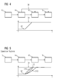
- the DPLL which keeps the rest of the components synchronous with the clock master, is generally optimized to suppress jitter. As a result, it can not follow the increment in the phase shift (see FIG. 5 ). Therefore, another synchronization method is used temporarily, which, although following the phase shift, can not suppress the jitter. In this other synchronization method, an abrupt adaptation of the clock period takes place.
- a disadvantage of this known method for synchronizing an isochronous base clock system with a hitherto independent, topologically higher clock system is that the sudden change of the clock period in addition to the remaining jitter an error-free communication with the clock master, for example, a violation of one of the component transmission time slot, is no longer guaranteed.
- One consequence of such no longer error-free communication is, for example, that the production machine is automatically stopped.
- An object of the invention is correspondingly to provide a method for synchronizing an isochronous base clock system with a previously independent, topologically superior clock system, in which the disadvantages outlined above are avoided or at least their effects are reduced.
- the base clock system comprises a plurality of synchronous components, each with a clock generator for generating local clocks, provided that in one the first step of the synchronization, a phase difference between an actual phase of the base clock system and a desired phase of the parent clock system is determined and the phase difference is transmitted to the components of the base clock system and that in a second step of the synchronization, the determined phase difference is used as feedforward of the clock generator of each component.
- DPLLs local clock generators of the components of the basic clock system, in particular DPLLs come into consideration, so that the following description is continued in the interests of better readability, but without abandoning a more general validity, the example of DPLLs as local clock generators.
- the solution proposed here requires the synchronicity of all clocks of the components included in the basic clock system with the communication clock of the clock master of this basic clock system achieved by means of the respective local DPLLs.
- information is generated in the clock master from the KGV cycle with suitable means, in particular suitable hardware, which is suitable for being transmitted to the individual components using conventional communication means. For this, the accuracy of this information is reduced to a resolution of one communication clock.
- All other components of the basic clock system can reconstruct the KGV clock of the clock master from this information and the communication clock.
- the consistency requirement for the clock master is fulfilled if all clocks of the own clock system fulfill the consistency requirement with respect to the communication clock and the reconstructed P / E clock.
- the production of this consistency condition is done by means of hardware, but controlled by an appropriate software.
- first all periods of the basic clock system are adapted, ie a respective phase difference between the base clock system and the higher-level clock system at the time of connection is taken as a setpoint and kept constant from now on. This step will be referred to as "snapping in”.
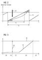
- a pre-calculated, planned and deterministic phase shift (see FIG. 3 ; Section B), ie a temporary and in all components simultaneously carried out feedforward control by means of setpoint input, within the entire base clock system eliminates the initial phase difference to the parent clock system.
- This step will be referred to as "dragging" in the following.
- phase difference determined in the first step and kept constant during the course of the first step makes it possible to determine the exact sequence of the second step in advance and optionally under
- the approach proposed here assumes that, for the base clock system to be adapted to the higher-level clock system, two clocks are selected that represent the entire base clock system, namely the communication clock and the KGV clock. This leads to a minimization of the information required for the synchronization.
- the aforementioned software routine by means of which the synchronicity of the or each (local) clock of each component of the basic clock system is monitored by the communication clock of the clock master is relieved of the actual execution of the synchronization with the higher-level clock system, without the control over the synchronicity to lose in relation to the communication clock of the Taktmaster.
- the software routine always has an influence on which clocks are synchronized with the communication clock of the clock master. However, the time of execution of the software routine no longer has to satisfy a time constraint.
- the advantage of the invention consists in the continuous control in the individual components of the basic clock system due to the respective local clock and its continuous synchronicity with the communication clock of the clock master and in that in the components of the basic clock system no change of the synchronization process is more necessary.
- the previous, error-prone switching between PLL synchronization and direct synchronization is eliminated.
- the DPLL remains engaged and does not change the operating state. Likewise, the suppression of the transmission jitter by the DPLL is ensured throughout the process.
- the invention is advantageously implemented in software.
- the invention is also a computer program with program code instructions which, when executed by means of a processing unit in the form of or in the manner of a microprocessor, effect an embodiment of the method described here and below.
- the computer program is executed on that component of the basic clock system which acts as a clock master in the basic clock system.
- the invention is also a computer program product, for example in the form of a digital storage medium, having a computer program with program code means or electronically readable control signals which can cooperate with a processing unit in the form of or in the manner of a microprocessor, a method as here and hereafter described and a production machine of the type mentioned, wherein in such a computer program is loaded or loadable in a memory of at least one of the production machine component.
- FIG. 1 1 shows, schematically greatly simplified, a device referred to below as basic clock system 10 with individual components 12, 14, 16, 18 included therein, wherein one of the components 12-18 functions as clock master 12 in the basic clock system 10 and wherein all the components 12-18 with each other, but in each case at least communicatively connected to the clock master 12 in a conventional manner.
- the device referred to here as base clock system 10 is, for example, a production machine according to the definition given at the outset.
- the clock master 12 outputs a communication clock 20 and a KGV clock 22.
- the period of the communication clock 20 predicts the period of the shortest local clock usable within the basic clock system 10 by the components 12-18.
- Those components 14-18 receiving the communication clock 20 from the clock master 12 synchronize all the local clocks with the communication clock 20 by means of a local DPLL.
- the KGV clock 22 is a system clock of the basic clock system 10 in which the beginning of each clock period coincides with the beginning of the clock cycle Clock periods of all other, mutually synchronized clocks coincide.
- FIG. 2 shows over the time axis t the course of the period of a local clock 24 of one of the components 12-18 of the base clock system 10 and the synchronization of this local clock 24 with the output from the clock master 12 KGV clock 22.
- the beginning of the period of the KGV clock 22 is in the illustration in FIG. 2 illustrated with the vertical, downward arrow.
- the beginning of the period of the KGV clock 22 falls apart with the beginning of the period of the local clock 24.
- the local clock 24 is consequently out of sync with the KGV clock 22.
- the period of the local clock 24 is extended.
- the phase position of the local clock 24 is checked for each local clock 24 by means of a counter, in particular a hardware counter (not shown) in each component 12-18, and optionally a phase shift is performed.
- a counter is started at the beginning of the period of the respective local clock 24 and stopped with the arrival of the KGV clock 22.
- the counter reading is then a measure of the phase of the local clock 24 relative to the KGV clock 22.
- the period of the local clock 24 is extended according to the previously determined count.
- the local clock 24 is extended at the end of the designated T1 normal period by exactly the duration of this triangle, so that the T2 designated extended period results. After turning on a period having such an extended period T2, the local clock 24 is in synchronism with the KGV clock 22.
- FIG. 3 shows in schematically simplified form the sequence of the method proposed here. It is assumed that an isochronous base clock system 10 (FIG. FIG. 1 ) with a previously independent, topologically superior clock system 30 ( FIG. 1 ), which may be another production machine or a parent device, is to be synchronized.
- FIG. 3 Over the time axis t is in FIG. 3 the phase difference between an actual phase 32 of the base clock system 10 and a target phase 34 of the higher-level clock system 30 is shown.
- the synchronization comprises a first and a second step and begins in the context of the first step with a phase called "locking in” (section B).
- an instantaneous value of the phase difference 36 between the actual phase 32 of the base clock system 10 and the setpoint phase 34 of the higher-order clock system 30 is detected and adopted as the setpoint for a synchronous feedforward control of the clock systems of the components 12-18 included in the basic clock system 10.
- the period of time for a determination of the Setpoint for the pilot control and for the distribution of the setpoint to the components 12-18 of the base clock system 10 is shown in FIG. 3 as an immediately following the "snapping in” phase (section C).
- the feedforward control of the components 12-18 of the base clock system 10 starts at the beginning of a PE cycle clock 22, so that the duration of the section C and the beginning of the subsequent second step of the synchronization of the base clock system 10 with the master clock system 30 from the next beginning of the period of the PER Clock 22 depends on the determination of the setpoint for the pilot control.
- the second step of the synchronization is a phase called "pull-in" (section D).
- the precontrol acts by supplying the previously determined phase difference 36 to the control loop of the local DPLLs of the individual components 12-18 of the basic clock system 10, in a manner known per se.
- FIG. 4 the components 12-18 of the basic clock system 10, which is fed from the clock master 12 of the determined phase difference 36 for synchronous pilot control.
Landscapes
- Engineering & Computer Science (AREA)
- Computer Networks & Wireless Communication (AREA)
- Signal Processing (AREA)
- Physics & Mathematics (AREA)
- General Physics & Mathematics (AREA)
- Automation & Control Theory (AREA)
- Synchronisation In Digital Transmission Systems (AREA)
Abstract
Die Erfindung ist ein Verfahren zur Synchronisation eines mehrere synchronisierte Komponenten (12-18) umfassenden Basistaktsystems (10) mit einem übergeordneten Taktsystem (30), wobei in einem ersten Schritt der Synchronisation ein Phasenunterschied (36) zwischen einer Istphase (32) des Basistaktsystems (10) und einer Sollphase (34) des übergeordneten Taktsystems (30) ermittelt wird und der Phasenunterschied (36) an die Komponenten (12-18) des Basistaktsystems (10) übermittelt wird und wobei in einem zweiten Schritt der Synchronisation der ermittelte Phasenunterschied (36) als Vorsteuerung jeder Komponente (12-18), nämlich zur Vorsteuerung eines Taktgenerators jeder Komponente (12-18), verwendet wird.The invention is a method for synchronizing a base clock system (10) comprising a plurality of synchronized components (12-18) with a higher-level clock system (30), wherein in a first step of synchronization a phase difference (36) between an actual phase (32) of the base clock system ( 10) and a desired phase (34) of the higher-order clock system (30) is determined and the phase difference (36) is transmitted to the components (12-18) of the base clock system (10) and wherein in a second step of the synchronization the determined phase difference (36 ) is used as a feedforward control of each component (12-18), namely for the precontrol of a clock generator of each component (12-18).
Description
Die Erfindung betrifft ein Verfahren zur Synchronisation eines isochronen Systems mit einem bisher unabhängigen, topologisch übergeordneten Taktsystem. Zur Unterscheidung vom dem übergeordneten Taktsystem wird das Taktsystem des isochronen Systems, das mit dem übergeordneten Taktsystem verbunden werden soll, im Folgenden als isochrones Basistaktsystem oder kurz als Basistaktsystem bezeichnet.The invention relates to a method for synchronizing an isochronous system with a hitherto independent, topologically superior clock system. In order to distinguish it from the higher-level clock system, the clock system of the isochronous system which is to be connected to the higher-level clock system is referred to below as an isochronous basic clock system or in short as a basic clock system.
Ein Beispiel für ein solches Basistaktsystem, das mehrere grundsätzlich unabhängige Komponenten oder Geräte - im Folgenden zusammenfassend als Komponenten bezeichnet - umfassen kann, ist ein System in Form einer Produktionsmaschine, einer Werkzeugmaschine, eines Roboters oder dergleichen. Ein solches System wird im Folgenden zusammenfassend, aber ohne Verzicht auf eine weitergehende Allgemeingültigkeit als Produktionsmaschine bezeichnet.An example of such a basic clock system, which may comprise several fundamentally independent components or devices - hereinafter collectively referred to as components - is a system in the form of a production machine, a machine tool, a robot or the like. Such a system is summarized below, but without renouncing a broader generality as a production machine referred to.
In einem derartigen Basistaktsystem werden bekanntlich mehrere Takte mit unterschiedlichen Perioden verwendet, die einerseits sämtlich zwischen den von dem Basistaktsystem umfassten Komponenten synchronisiert werden müssen und die andererseits auch untereinander in einer definierten Phasenbeziehung zueinander stehen müssen.In such a basic clock system, it is known to use a plurality of clocks having different periods, which on the one hand must be synchronized between the components encompassed by the basic clock system and, on the other hand, must also be in a defined phase relationship with one another.
Dabei werden folgende Konsistenzbedingungen vorausgesetzt:
- Eine als Taktmaster fungierende Komponente gibt an die übrigen von dem Basistaktsystem umfassten Komponenten einen im Folgenden als Kommunikationstakt bezeichneten Takt aus. Die Periode des Kommunikationstakts bestimmt den kürzesten im Basistaktsystem verwendbaren Takt. Alle Komponenten synchronisieren sich mittels eines lokalen Taktgenerators, insbesondere einer lokalen, digitalen PLL (DPLL), auf den Kommunikationstakt und der Beginn der Taktperiode jedes anderen Takts im Basistaktsystem fällt stets mit dem Beginn einer Periode des Kommunikationstakts zusammen.
- Neben dem Kommunikationstakt wird vom Taktmaster ein spezieller Systemtakt erzeugt, bei dem der Beginn jeder Taktperiode mit dem Beginn der Taktperioden aller anderen, untereinander synchronisierten Takte zusammenfällt. Die Periode eines solchen Takts ist das kleinste gemeinsame Vielfache der Perioden aller anderen Takte des Basistaktsystems. Entsprechend wird dieser als KGV-Takt (KGV = kleinstes gemeinsames Vielfaches) bezeichnet.
- A component acting as a clock master outputs to the other components included in the basic clock system a clock referred to below as the communication clock. The period of the communication clock determines the shortest clock usable in the basic clock system. All components synchronize themselves by means of a local clock generator, in particular a local digital PLL (DPLL), to the communication clock and the beginning of the clock period of each other clock in the basic clock system always coincides with the beginning of a period of the communication clock.
- In addition to the communication clock, the clock master generates a special system clock in which the beginning of each clock period coincides with the beginning of the clock periods of all other clocks synchronized with each other. The period of such a clock is the least common multiple of the periods of all other clocks of the basic clock system. Accordingly, this is referred to as KGV clock (KGV = least common multiple).
Auf Basis des von Taktmaster ausgegebenen Kommunikationstakts erzeugt jede von dem Basistaktsystem umfasste Komponente ein eigenständiges Taktsystem, das mithilfe eines lokalen Taktgenerators (lokaler DPLL) und anderer geeigneter Maßnahmen die Konsistenzbedingungen in Bezug auf das Taktsystem des Taktmasters erfüllt. Dabei wird für jede von dem Basistaktsystem umfasste Komponente jede bereits erreichte Konsistenzbedingung - teilweise mithilfe einer DPLL - aufrechterhalten.Based on the clock clock output by the clock master, each component included in the base clock system generates a stand-alone clock system that satisfies the consistency requirements with respect to the clock master clock system using a local clock generator (local DPLL) and other appropriate means. For each component covered by the base clock system, each consistency condition already achieved is maintained, in part using a DPLL.
Zum Verbinden eines solchen isochronen Basistaktsystems mit einem bisher unabhängigen, topologisch übergeordneten Taktsystem müssen alle Takte des Basistaktsystems phasenverschoben werden, damit sich beide Systeme zu einem isochronen Gesamtsystem vereinen. Die Phasenverschiebung muss dabei so erfolgen, dass einerseits die Konsistenz der Takte untereinander und über die verschiedenen Komponenten des Basistaktsystems hinweg zu keinem Zeitpunkt unzulässig gestört wird und dass andererseits nach der Phasenverschiebung die Vereinigung der Taktsysteme so möglich ist, dass die genannten Konsistenzbedingungen auch für das Gesamtsystem gelten.In order to connect such an isochronous basic clock system with a hitherto independent, topologically superior clock system, all clocks of the basic clock system must be phase-shifted, so that both systems combine to form an overall isochronous system. The phase shift must be such that on the one hand the consistency of the clocks among each other and over the various components of the basic clock system is never unduly disturbed and that on the other hand after the phase shift, the union of the clock systems is possible that the consistency conditions mentioned for the entire system be valid.
Bisher ist bei einem Verfahren zur Synchronisation eines isochronen Systems mit einem übergeordneten Taktsystem vorgesehen, dass die Konsistenzbedingungen aller lokalen Takte innerhalb einer Komponente mittels einer Software-Routine eingestellt und überprüft werden. Dabei wird anhand von Hardware-Zählern die Phasenlage der Takte geprüft und es wird gegebenenfalls eine Phasenverschiebung programmiert, die dann allerdings in Hardware ausgeführt wird. Dies gelingt nur, wenn die Hardware-Zähler der verschiedenen Takte konsistent ausgelesen werden, d.h. wenn sichergestellt ist, dass alle Zähler ausgelesen werden können, bevor sich ein Zählerstand ändert. In einem Echtzeitsystem bedeutet dies, dass diese Software-Routine der schnellsten Zeitscheibe zugeordnet sein muss.So far, in a method for synchronizing an isochronous system with a higher-order clock system, it is provided that the consistency conditions of all local clocks within a component are set by means of a software routine and be checked. In this case, the phase position of the clocks is checked by means of hardware counters and, if necessary, a phase shift is programmed which is then executed in hardware. This is possible only if the hardware counters of the various clocks are read out consistently, ie if it is ensured that all counters can be read out before a counter reading changes. In a real-time system this means that this software routine must be assigned to the fastest time slot.
Zwischen verschiedenen Komponenten können die Konsistenzbedingungen nur durch Beobachtung der Kommunikation erfüllt werden, die zu vorher festgelegten Zeitpunkten mit durch ein jeweiliges Protokoll definierten Telegrammen erfolgt. Für eine gezielte Synchronisation müsste der Zeitpunkt, zu dem die oben genannte Software-Routine läuft, nicht nur auf die internen Zähler sondern auch auf die Kommunikation ausgerichtet werden. Zur Vermeidung dieser zusätzlichen Randbedingung werden die Phasen der betroffenen Takte nicht gezielt sondern schrittweise verändert, bis eine fehlerfreie Kommunikation erkennen lässt, dass die Konsistenzbedingung erfüllt ist.Between different components, the consistency conditions can only be met by observing the communication that occurs at predetermined times with telegrams defined by a respective protocol. For a targeted synchronization, the time at which the software routine mentioned above would have to be geared not only to the internal counter but also to the communication. In order to avoid this additional boundary condition, the phases of the clocks affected are not modified in a targeted manner, but gradually, until an error-free communication indicates that the consistency condition has been met.
Bei der Verbindung mit einem übergeordneten Taktsystem teilt der Taktmaster des Basistaktsystems zunächst allen Komponenten des Basistaktsystems mit, dass eine Phasenverschiebung erfolgt. Bei dem bisherigen Verfahren verschiebt der Taktmaster dann solange sein eigenes Taktsystem, bis es mit dem übergeordneten Taktsystem synchron ist. Dabei verwendet der Taktmaster eine konstante Schrittweite pro Kommunikationstakt. Schließlich teilt der Taktmaster den anderen Komponenten des Basistaktsystems mit, dass die Phasenverschiebung abgeschlossen ist.When connected to a higher-level clock system, the clock master of the basic clock system initially notifies all components of the basic clock system that a phase shift occurs. In the previous method, the clock master then shifts its own clock system until it is synchronized with the higher-level clock system. The clock master uses a constant step size per communication cycle. Finally, the clock master notifies the other components of the basic clock system that the phase shift has been completed.
Auf diese Weise ist eine Synchronizität des Taktmasters des Basistaktsystems mit dem übergeordneten Taktsystem erreicht. Während dieser Anpassung und nach der Anpassung gibt der Taktmaster kontinuierlich den für alle Komponenten des Basistaktsystems maßgeblichen Kommunikationstakt aus.In this way, a synchronicity of the clock master of the basic clock system is achieved with the parent clock system. During this adjustment and after adjustment, the Clock master continuously from the decisive for all components of the basic clock system communication clock.
Die DPLL, mit der sich die übrigen Komponenten synchron zum Taktmaster halten, ist aber im Allgemeinen zur Unterdrückung von Störrauschen (Jitter) optimiert. Dadurch kann sie der Schrittweite bei der Phasenverschiebung nicht folgen (siehe
Nachteilig bei diesem bekannten Verfahren zur Synchronisation eines isochronen Basistaktsystems mit einem bisher unabhängigen, topologisch übergeordneten Taktsystem ist, dass durch die sprunghafte Änderung der Taktperiode in Addition zu dem verbleibenden Jitter eine fehlerfreie Kommunikation mit dem Taktmaster, zum Beispiel einer Verletzung eines der Komponente zugeordneten Sendezeitschlitzes, nicht mehr gewährleistet ist. Eine Folge eines solchen nicht mehr fehlerfreien Kommunikation ist zum Beispiel, dass die Produktionsmaschine automatisch angehalten wird.A disadvantage of this known method for synchronizing an isochronous base clock system with a hitherto independent, topologically higher clock system is that the sudden change of the clock period in addition to the remaining jitter an error-free communication with the clock master, for example, a violation of one of the component transmission time slot, is no longer guaranteed. One consequence of such no longer error-free communication is, for example, that the production machine is automatically stopped.
Eine Aufgabe der Erfindung besteht entsprechend darin, ein Verfahren zur Synchronisation eines isochronen Basistaktsystems mit einem bisher unabhängigen, topologisch übergeordneten Taktsystem anzugeben, bei dem die oben skizzierten Nachteile vermieden werden oder zumindest deren Auswirkungen reduziert sind.An object of the invention is correspondingly to provide a method for synchronizing an isochronous base clock system with a previously independent, topologically superior clock system, in which the disadvantages outlined above are avoided or at least their effects are reduced.
Diese Aufgabe wird erfindungsgemäß mittels eines Verfahrens zur Synchronisation eines isochronen Basistaktsystems mit einem bisher unabhängigen, topologisch übergeordneten Taktsystem mit den Merkmalen des Anspruchs 1 gelöst. Dazu ist bei einem solchen Verfahren, wobei das Basistaktsystem mehrere synchrone Komponenten mit jeweils einem Taktgenerator zur Generierung lokaler Takte umfasst, vorgesehen, dass in einem ersten Schritt der Synchronisation ein Phasenunterschied zwischen einer Istphase des Basistaktsystems und einer Sollphase des übergeordneten Taktsystems ermittelt wird und der Phasenunterschied an die Komponenten des Basistaktsystems übermittelt wird sowie dass in einem zweiten Schritt der Synchronisation der ermittelte Phasenunterschied als Vorsteuerung des Taktgenerators jeder Komponente verwendet wird. Als lokale Taktgeneratoren der Komponenten des Basistaktsystems kommen insbesondere DPLLs in Betracht, so dass die nachfolgende Beschreibung im Interesse einer besseren Lesbarkeit, aber ohne Verzicht auf eine weitergehende Allgemeingültigkeit, am Beispiel von DPLLs als lokalen Taktgeneratoren fortgesetzt wird.This object is achieved by means of a method for synchronizing an isochronous base clock system with a previously independent, topologically superior clock system with the features of claim 1. For this purpose, in such a method, wherein the base clock system comprises a plurality of synchronous components, each with a clock generator for generating local clocks, provided that in one the first step of the synchronization, a phase difference between an actual phase of the base clock system and a desired phase of the parent clock system is determined and the phase difference is transmitted to the components of the base clock system and that in a second step of the synchronization, the determined phase difference is used as feedforward of the clock generator of each component. As local clock generators of the components of the basic clock system, in particular DPLLs come into consideration, so that the following description is continued in the interests of better readability, but without abandoning a more general validity, the example of DPLLs as local clock generators.
Die hier vorgeschlagene Lösung setzt die mithilfe der jeweils lokalen DPLLs erreichte Synchronizität aller Takte der von dem Basistaktsystem umfassten Komponenten mit dem Kommunikationstakt des Taktmasters dieses Basistaktsystems voraus. Zunächst wird im Taktmaster aus dem KGV-Takt mit dafür geeigneten Mitteln, insbesondere einer geeigneten Hardware, eine Information erzeugt, welche sich dafür eignet, mit üblichen Kommunikationsmitteln zu den einzelnen Komponenten übertragen zu werden. Dafür wird die Genauigkeit dieser Information auf eine Auflösung von einem Kommunikationstakt reduziert. Alle übrigen Komponenten des Basistaktsystems können aus dieser Information und dem Kommunikationstakt den KGV-Takt des Taktmasters rekonstruieren. Die Konsistenzbedingung zum Taktmaster ist erfüllt, wenn alle Takte des eigenen Taktsystems die Konsistenzbedingung bezüglich des Kommunikationstakts und des rekonstruierten KGV-Takts erfüllen. Die Herstellung dieser Konsistenzbedingung erfolgt mittels Hardware, allerdings gesteuert durch eine entsprechende Software.The solution proposed here requires the synchronicity of all clocks of the components included in the basic clock system with the communication clock of the clock master of this basic clock system achieved by means of the respective local DPLLs. First of all, information is generated in the clock master from the KGV cycle with suitable means, in particular suitable hardware, which is suitable for being transmitted to the individual components using conventional communication means. For this, the accuracy of this information is reduced to a resolution of one communication clock. All other components of the basic clock system can reconstruct the KGV clock of the clock master from this information and the communication clock. The consistency requirement for the clock master is fulfilled if all clocks of the own clock system fulfill the consistency requirement with respect to the communication clock and the reconstructed P / E clock. The production of this consistency condition is done by means of hardware, but controlled by an appropriate software.
Die Anpassung des Basistaktsystems nach der Verbindung mit einem übergeordneten Taktsystem erfolgt im Gegensatz zu bisher in zwei voneinander unabhängigen Schritten:The adaptation of the basic clock system after the connection with a higher-level clock system takes place in contrast to previously in two independent steps:
In einem ersten Schritt werden zunächst alle Perioden des Basistaktsystems angepasst, d.h. ein jeweiliger Phasenunterschied zwischen dem Basistaktsystem und dem übergeordneten Taktsystem zum Zeitpunkt der Verbindung wird als Sollwert übernommen und ab sofort konstant gehalten. Dieser Schritt wird im Folgenden als "Einrasten" bezeichnet.In a first step, first all periods of the basic clock system are adapted, ie a respective phase difference between the base clock system and the higher-level clock system at the time of connection is taken as a setpoint and kept constant from now on. This step will be referred to as "snapping in".
In einem zweiten Schritt wird mittels einer vorab berechneten, geplanten und deterministischen Phasenverschiebung (siehe
Der im ersten Schritt ermittelte und während des Ablaufs des ersten Schritts konstant gehaltene Phasenunterschied ermöglicht es, den genauen Ablauf des zweiten Schritts im Voraus sowie optional unterThe phase difference determined in the first step and kept constant during the course of the first step makes it possible to determine the exact sequence of the second step in advance and optionally under
Berücksichtigung zusätzlicher Randbedingungen, z.B. einer maximal zulässigen Verzugsgeschwindigkeit, Vorgaben zur Einhaltung des Sendezeitschlitzes, Limitierungen in der Hardware, etc., zu berechnen und das Ergebnis dieser Berechnung unter Verwendung üblicher Kommunikationsmittel allen Komponenten des Basistaktsystems mitzuteilen (siehe
- 1. Die Vorsteuerung startet nur am Beginn eines KGV-Takts. Die Kommunikation der Komponenten wird um ein Kommunikationsmittel, zum Beispiel durch Einführung oder Erweiterung eines Prozessdatums, durch Erweiterung des Telegrammheaders, etc., erweitert, das es ermöglicht, den Startzeitpunkt des KGV-Takts redundant zu übertragen.
- 2. Die Phasenverschiebung wird von jeder DPLL als zeitlich begrenzte Vorsteuerung berücksichtigt. Der Regler der DPLL interpretiert demnach die Phasenverschiebung nicht als auszuregelnde Störung sondern als geplante Sollwertaufschaltung.
- 1. The feedforward starts only at the beginning of a KGV cycle. The communication of the components is a means of communication, for example by introducing or extending a Extended process data, by extension of the telegram header, etc., which makes it possible to transmit the start time of the KGV clock redundant.
- 2. The phase shift is considered by each DPLL as a time-limited feedforward control. The controller of the DPLL therefore interprets the phase shift not as a disturbance to be corrected but as a planned setpoint input.
Der hier vorgeschlagene Ansatz geht davon aus, dass für das an das übergeordnete Taktsystem anzupassende Basistaktsystem zwei Takte ausgewählt werden, die das gesamte Basistaktsystem repräsentieren, nämlich der Kommunikationstakt und der KGV-Takt. Dies führt zu einer Minimierung der für die Synchronisation benötigten Information.The approach proposed here assumes that, for the base clock system to be adapted to the higher-level clock system, two clocks are selected that represent the entire base clock system, namely the communication clock and the KGV clock. This leads to a minimization of the information required for the synchronization.
Die eingangs genannte Software-Routine, mittels derer die Synchronizität des oder jedes (lokalen) Takts einer jeden Komponente des Basistaktsystems mit dem Kommunikationstakt des Taktmasters überwacht wird, wird von der konkreten Durchführung der Synchronisation mit dem übergeordneten Taktsystem entlastet, ohne die Kontrolle über die Synchronizität in Bezug auf den Kommunikationstakt des Taktmasters zu verlieren. Die Software-Routine hat jederzeit Einfluss darauf, welche Takte wann mit dem Kommunikationstakt des Taktmasters synchronisiert werden. Der Zeitpunkt der Ausführung der Software-Routine muss aber keiner zeitlichen Randbedingung mehr genügen.The aforementioned software routine, by means of which the synchronicity of the or each (local) clock of each component of the basic clock system is monitored by the communication clock of the clock master is relieved of the actual execution of the synchronization with the higher-level clock system, without the control over the synchronicity to lose in relation to the communication clock of the Taktmaster. The software routine always has an influence on which clocks are synchronized with the communication clock of the clock master. However, the time of execution of the software routine no longer has to satisfy a time constraint.
Die notwendige Kommunikation zwischen den Komponenten des Basistaktsystems wird auf ein Minimum reduziert: Für die Rekonstruktion des KGV-Takts des Taktmasters ist die Übertragung von lediglich 1 Bit nötig, das im Rahmen der ohnehin stattfindenden Kommunikation transportiert werden kann, zum Beispiel im Telegramheader oder einem Prozessdatum.The necessary communication between the components of the basic clock system is reduced to a minimum: For the reconstruction of the KGV clock of the clock master the transmission of only 1 bit is necessary, which can be transported in the context of already occurring communication, for example in the telegram header or a process date ,
Die Anpassung an das übergeordnete Taktsystem erfolgt damit insgesamt als vollständig geplanter, deterministischer Vorgang. Auch auf den einzelnen Komponenten des Basistaktsystems ablaufende Applikationssoftware wird über den Beginn und das Ende der Sollwertaufschaltung informiert und kann entsprechend deren Effekte innerhalb der Applikation gegebenenfalls kompensieren. Dies ermöglicht und erleichtert nötigenfalls den Weiterbetrieb kritischer Anlagen während des gesamten Synchronisationsvorgangs.Overall, the adaptation to the higher-level clock system takes place as a completely planned, deterministic process. Also on the individual components of the base clock system running application software is informed about the beginning and end of the setpoint connection and can compensate for their effects within the application, if necessary. This allows and facilitates, if necessary, the continued operation of critical assets during the entire synchronization process.
Der Vorteil der Erfindung besteht in der in den einzelnen Komponenten des Basistaktsystems kontinuierlich weiterlaufenden Regelung aufgrund des jeweiligen lokalen Takts und dessen kontinuierlicher Synchronizität mit dem Kommunikationstakt des Taktmasters sowie darin, dass in den Komponenten des Basistaktsystems kein Wechsel des Synchronisationsverfahrens mehr nötig ist. Die bisherige, fehleranfällige Umschaltung zwischen PLL-Synchronisation und direkter Synchronisation entfällt. Die DPLL bleibt im Eingriff und wechselt nicht den Betriebszustand. Ebenso bleibt die Unterdrückung des Übertragungsjitters durch die DPLL während des gesamten Vorgangs gewährleistet.The advantage of the invention consists in the continuous control in the individual components of the basic clock system due to the respective local clock and its continuous synchronicity with the communication clock of the clock master and in that in the components of the basic clock system no change of the synchronization process is more necessary. The previous, error-prone switching between PLL synchronization and direct synchronization is eliminated. The DPLL remains engaged and does not change the operating state. Likewise, the suppression of the transmission jitter by the DPLL is ensured throughout the process.
Das gesamte Verfahren stützt sich auf abgesicherte und redundant durchgeführte Übertragungen. Der Ausfall einzelner Übertragungen kann im Gegensatz zum bisherigen Verfahren zu keinem Zeitpunkt zum Verlust der Synchronizität einer Komponente führen.The entire process relies on secured and redundant transmissions. The failure of individual transmissions, in contrast to the previous method at no time lead to loss of synchronicity of a component.
Die Erfindung ist vorteilhaft in Software implementiert. Insoweit ist die Erfindung auch ein Computerprogramm mit Programmcodeanweisungen die bei einer Ausführung mittels einer Verarbeitungseinheit in Form von oder nach Art eines Mikroprozessors eine Ausführung des hier und im Folgenden beschriebenen Verfahrens bewirken. Die Ausführung des Computerprogramms erfolgt auf derjenigen Komponente des Basistaktsystems, die in dem Basistaktsystem als Taktmaster fungiert. Soweit bei der Erläuterung des gegenständlichen Verfahrens und spezieller Ausführungsformen einer Ausführung einzelner Aktionen (ermitteln, übertragen, verwenden, etc.) beschrieben ist, erfolgt stets eine automatische Ausführung solcher Aktionen, zum Beispiel unter Kontrolle des Computerprogramms oder entsprechender Verarbeitungsfunktionalität der weiteren von dem Basistaktsystem umfassten Komponenten.The invention is advantageously implemented in software. In that regard, the invention is also a computer program with program code instructions which, when executed by means of a processing unit in the form of or in the manner of a microprocessor, effect an embodiment of the method described here and below. The computer program is executed on that component of the basic clock system which acts as a clock master in the basic clock system. As far as the explanation of the subject method and specific embodiments of an execution of individual actions (determine, transfer, use, etc.) is described, there is always an automatic execution of such actions, for example, under control of the computer program or corresponding processing functionality of the other components covered by the base clock system.
Die Erfindung ist schließlich auch ein Computerprogrammprodukt, zum Beispiel in Form eines digitalen Speichermediums, mit einem Computerprogramm mit Programmcodemitteln oder elektronisch auslesbaren Steuersignalen, die so mit einer Verarbeitungseinheit in Form von oder nach Art eines Mikroprozessors zusammenwirken können, dass ein Verfahren wie hier und im Folgenden beschrieben ausgeführt wird sowie eine Produktionsmaschine der eingangs genannten Art, wobei in einen Speicher zumindest einer von der Produktionsmaschine umfassten Komponente ein solches Computerprogramm geladen oder ladbar ist.Finally, the invention is also a computer program product, for example in the form of a digital storage medium, having a computer program with program code means or electronically readable control signals which can cooperate with a processing unit in the form of or in the manner of a microprocessor, a method as here and hereafter described and a production machine of the type mentioned, wherein in such a computer program is loaded or loadable in a memory of at least one of the production machine component.
Vorteilhafte Ausgestaltungen der Erfindung sind Gegenstand der Unteransprüche. Dabei verwendete Rückbeziehungen weisen auf die weitere Ausbildung des Gegenstandes des Hauptanspruches durch die Merkmale des jeweiligen Unteranspruches hin. Sie sind nicht als ein Verzicht auf die Erzielung eines selbständigen, gegenständlichen Schutzes für die Merkmalskombinationen der rückbezogenen Unteransprüche zu verstehen. Des Weiteren ist im Hinblick auf eine Auslegung der Ansprüche bei einer näheren Konkretisierung eines Merkmals in einem nachgeordneten Anspruch davon auszugehen, dass eine derartige Beschränkung in den jeweils vorangehenden Ansprüchen nicht vorhanden ist. Schließlich ist darauf hinzuweisen, dass das hier angegebene Verfahren auch entsprechend der abhängigen Vorrichtungsansprüche weitergebildet sein kann und umgekehrt.Advantageous embodiments of the invention are the subject of the dependent claims. Here used backlinks indicate the further development of the subject matter of the main claim by the features of the respective subclaim. They should not be construed as a waiver of obtaining independent, objective protection for the feature combinations of the dependent claims. Furthermore, with a view to an interpretation of the claims in a closer specification of a feature in a subordinate claim, it is to be assumed that such a restriction does not exist in the respective preceding claims. Finally, it should be noted that the method specified here can also be developed according to the dependent device claims and vice versa.
Nachfolgend wird ein Ausführungsbeispiel der Erfindung anhand der Zeichnung näher erläutert. Einander entsprechende Gegenstände oder Elemente sind in allen Figuren mit den gleichen Bezugszeichen versehen.An embodiment of the invention will be explained in more detail with reference to the drawing. Corresponding objects or elements are provided in all figures with the same reference numerals.
Das oder jedes Ausführungsbeispiel ist nicht als Einschränkung der Erfindung zu verstehen. Vielmehr sind im Rahmen der vorliegenden Offenbarung zahlreiche Abänderungen und Modifikationen möglich, insbesondere solche Varianten und Kombinationen, die zum Beispiel durch Kombination oder Abwandlung von einzelnen in Verbindung mit den im allgemeinen oder speziellen Beschreibungsteil beschriebenen sowie in den Ansprüchen und/oder der Zeichnung enthaltenen Merkmalen bzw. Elementen oder Verfahrensschritten für den Fachmann im Hinblick auf die Lösung der Aufgabe entnehmbar sind und durch kombinierbare Merkmale zu einem neuen Gegenstand oder zu neuen Verfahrensschritten bzw. Verfahrensschrittfolgen führen.The or each embodiment is not to be understood as limiting the invention. Rather, numerous modifications and variations are possible within the scope of the present disclosure, in particular those variants and combinations, for example, by combination or modification of individual features described in the general or specific description part as well as in the claims and / or the drawing Elements or process steps for the expert with regard to the solution of the problem can be removed and lead by combinable features to a new subject or to new process steps or process steps.
Es zeigen
- FIG 1
- eine schematisch vereinfachte Darstellung einer im Folgenden als Basistaktsystem aufgefassten Produktionsmaschine,
- FIG 2
- eine Darstellung zur Erläuterung einer Synchronisation lokaler Takte mit einem Systemtakt (KGV-Takt),
- FIG 3
- eine schematisch vereinfachte Darstellung eines Ablaufs einer Synchronisation des Basistaktsystems mit einem übergeordneten Taktsystem gemäß dem hier vorgeschlagenen Verfahren,
- FIG 4
- eine Darstellung des Basistaktsystems zusammen mit dem Ablauf des hier vorgeschlagenen Verfahrens, sowie
- FIG 5
- zur Gegenüberstellung mit der Darstellung in
FIG 4 einen bisherigen Ablauf einer Synchronisation eines Basistaktsystems mit einem übergeordneten Taktsystem.
- FIG. 1
- a schematically simplified representation of a production machine, which will be referred to below as a basic clock system,
- FIG. 2
- a representation for explaining a synchronization of local clocks with a system clock (KGV clock),
- FIG. 3
- a schematically simplified representation of a sequence of a synchronization of the basic clock system with a higher-order clock system according to the method proposed here,
- FIG. 4
- a representation of the basic clock system together with the flow of the method proposed here, as well as
- FIG. 5
- to the comparison with the representation in
FIG. 4 a previous sequence of synchronization of a basic clock system with a parent clock system.
Die Darstellung in
Zur Synchronisation aller vom Basistaktsystem 10 umfassten Komponenten 12-18 gibt der Taktmaster 12 einen Kommunikationstakt 20 sowie einen KGV-Takt 22 aus. Die Periode des Kommunikationstakts 20 gibt die Periode des kürzesten innerhalb des Basistaktsystems 10 durch die Komponenten 12-18 verwendbaren lokalen Takts vor. Diejenigen Komponenten 14-18, die vom Taktmaster 12 den Kommunikationstakt 20 erhalten, synchronisieren alle lokalen Takte mittels einer lokalen DPLL mit dem Kommunikationstakt 20. Der KGV-Takt 22 ist ein Systemtakt des Basistaktsystems 10, bei dem der Beginn jeder Taktperiode mit dem Beginn der Taktperioden aller anderen, untereinander synchronisierten Takte zusammenfällt.To synchronize all components 12-18 included in the
Die Darstellung in
Um Synchronizität herzustellen wird die Periodendauer des lokalen Takts 24 verlängert. Dafür wird mittels eines Zählers, insbesondere eines Hardwarezählers (nicht gezeigt) in jeder Komponente 12-18 für jeden lokalen Takt 24 die Phasenlage des lokalen Takts 24 geprüft und gegebenenfalls eine Phasenverschiebung vorgenommen. Ein solcher Zähler wird mit Beginn der Periode des jeweiligen lokalen Takts 24 gestartet und mit dem Eintreffen des KGV-Takts 22 gestoppt. Der Zählerstand ist dann ein Maß für die Phasenlage des lokalen Takts 24 relativ zum KGV-Takt 22. Um Synchronizität des lokalen Takts 24 mit dem KGV-Takt 22 zu erreichen, wird die Periodendauer des lokalen Takts 24 entsprechend dem zuvor ermittelten Zählerstand verlängert.To establish synchronicity, the period of the
Dies ist in der Darstellung in
Die Darstellung in
Über der Zeitachse t ist dabei in
Die Vorsteuerung der Komponenten 12-18 des Basistaktsystems 10 startet am Beginn eines KGV-Takts 22, so dass die Dauer des Abschnitts C und der Beginn des anschließenden zweiten Schrittes der Synchronisation des Basistaktsystems 10 mit dem übergeordneten Taktsystem 30 vom nächsten Beginn der Periode des KGV-Takts 22 nach der Ermittlung des Sollwerts für die Vorsteuerung abhängt. Der zweite Schritt der Synchronisation besteht in einer als "Hinziehen" bezeichneten Phase (Abschnitt D). Während dieser Phase wirkt die Vorsteuerung, indem - in an sich bekannter Art und Weise - der zuvor ermittelte Phasenunterschied 36 dem Regelkreis der lokalen DPLLs der einzelnen Komponenten 12-18 des Basistaktsystems 10 zugeführt wird. Dazu zeigt die Darstellung in
Im unteren Bereich der Darstellung in
Im Vergleich dazu ist in der Darstellung in
Sobald eine Synchronizität mit dem übergeordneten Taktsystem 30 besteht, endet die Phase des "Hinziehens" und die Vorsteuerung wird deaktiviert. Die beiden Systeme 10,30 sind synchron (
Obwohl die Erfindung im Detail durch das Ausführungsbeispiel näher illustriert und beschrieben wurde, so ist die Erfindung nicht durch das oder die offenbarten Beispiele eingeschränkt und andere Variationen können vom Fachmann hieraus abgeleitet werden, ohne den Schutzumfang der Erfindung zu verlassen.While the invention has been further illustrated and described in detail by the exemplary embodiment, the invention is not limited by the disclosed or disclosed examples, and other variations can be derived therefrom by those skilled in the art without departing from the scope of the invention.
Einzelne im Vordergrund stehende Aspekte der hier eingereichten Beschreibung lassen sich damit kurz wie folgt zusammenfassen: Angegeben wird ein Verfahren zur Synchronisation eines mehrere synchronisierte Komponenten 12-18 umfassenden Basistaktsystems 10 mit einem übergeordneten Taktsystem 30, wobei in einem ersten Schritt der Synchronisation ein Phasenunterschied 36 zwischen einer Istphase 32 des Basistaktsystems 10 und einer Sollphase 34 des übergeordneten Taktsystems 30 ermittelt wird und der Phasenunterschied 36 an die Komponenten 12-18 des Basistaktsystems 10 übermittelt wird und wobei in einem zweiten Schritt der Synchronisation der ermittelte Phasenunterschied 36 als Vorsteuerung jeder Komponente 12-18, nämlich zur Vorsteuerung eines Taktgenerators jeder Komponente 12-18, verwendet wird.Individual foregrounding aspects of the description submitted here can thus be briefly summarized as follows: A method is disclosed for synchronizing a
Claims (7)
wobei das Basistaktsystem (10) mehrere synchrone Komponenten (12-18) mit jeweils einem Taktgenerator zur Generierung lokaler Takte umfasst,
wobei in einem ersten Schritt der Synchronisation ein Phasenunterschied (36) zwischen einer Istphase (32) des Basistaktsystems (10) und einer Sollphase (34) des übergeordneten Taktsystems (30) ermittelt wird und der Phasenunterschied (36) an die Komponenten (12-18) des Basistaktsystems (10) übermittelt wird und
wobei in einem zweiten Schritt der Synchronisation der ermittelte Phasenunterschied (36) als Vorsteuerung des Taktgenerators jeder Komponente (12-18) verwendet wird.Method for synchronizing an isochronous basic clock system (10) with a higher-order clock system (30),
wherein the base clock system (10) comprises a plurality of synchronous components (12-18) each having a clock generator for generating local clocks,
wherein in a first step of the synchronization, a phase difference (36) between an actual phase (32) of the base clock system (10) and a desired phase (34) of the higher clock system (30) is determined and the phase difference (36) to the components (12-18 ) of the basic clock system (10) is transmitted and
wherein, in a second step of the synchronization, the determined phase difference (36) is used as feed forward of the clock generator of each component (12-18).
wobei eine in dem Basistaktsystem (10) als Taktmaster (12) fungierende Komponente (12) für die von dem Basistaktsystem (10) umfassten weiteren Komponenten (14-18) einen Kommunikationstakt (20) und einen KGV-Takt (22) generiert,
wobei alle von den Komponenten (12-18) verwendeten lokalen Takte (24) mit dem Kommunikationstakt (20) synchron sind und eine Periode des KGV-Takts (22) das kleinste gemeinsame Vielfache der Perioden aller anderen Takte (24) des Basistaktsystems (10) ist und
wobei der zweite Schritt der Synchronisation und die Vorsteuerung der Taktgeneratoren der Komponenten (12-18) des Basistaktsystems mit dem Beginn einer Periode des KGV-Takts (22) beginnt.Method according to claim 1 or 2,
wherein a component (12) functioning as a clock master (12) in the base clock system (10) generates a communication clock (20) and a KGV clock (22) for the further components (14-18) included in the basic clock system (10),
wherein all the local clocks (24) used by the components (12-18) are synchronous with the communication clock (20) and one period of the P / E clock (22) is the least common multiple of the periods of all the other clocks (24) of the basic clock system (10 ) is and
wherein the second step of synchronization and feedforward of the clock generators of the components (12-18) of the base clock system commence at the beginning of a period of the P / E clock (22).
Priority Applications (3)
| Application Number | Priority Date | Filing Date | Title |
|---|---|---|---|
| EP14163047.5A EP2928110B1 (en) | 2014-04-01 | 2014-04-01 | Method for synchronising an isochronous system with a higher level clock system |
| US14/674,937 US9544129B2 (en) | 2014-04-01 | 2015-03-31 | Method for synchronizing an isochronous system with a higher-ranking clock pulse system |
| CN201510149474.7A CN104980265B (en) | 2014-04-01 | 2015-03-31 | System whens for that will the wait method synchronous with supervisory clock system |
Applications Claiming Priority (1)
| Application Number | Priority Date | Filing Date | Title |
|---|---|---|---|
| EP14163047.5A EP2928110B1 (en) | 2014-04-01 | 2014-04-01 | Method for synchronising an isochronous system with a higher level clock system |
Publications (2)
| Publication Number | Publication Date |
|---|---|
| EP2928110A1 true EP2928110A1 (en) | 2015-10-07 |
| EP2928110B1 EP2928110B1 (en) | 2020-10-07 |
Family
ID=50397013
Family Applications (1)
| Application Number | Title | Priority Date | Filing Date |
|---|---|---|---|
| EP14163047.5A Active EP2928110B1 (en) | 2014-04-01 | 2014-04-01 | Method for synchronising an isochronous system with a higher level clock system |
Country Status (3)
| Country | Link |
|---|---|
| US (1) | US9544129B2 (en) |
| EP (1) | EP2928110B1 (en) |
| CN (1) | CN104980265B (en) |
Families Citing this family (1)
| Publication number | Priority date | Publication date | Assignee | Title |
|---|---|---|---|---|
| DE102017223331A1 (en) * | 2017-12-20 | 2019-06-27 | Audi Ag | Control of a chassis component of a vehicle |
Citations (5)
| Publication number | Priority date | Publication date | Assignee | Title |
|---|---|---|---|---|
| US4694472A (en) * | 1982-04-26 | 1987-09-15 | American Telephone And Telegraph Company | Clock adjustment method and apparatus for synchronous data communications |
| DE4215380A1 (en) * | 1992-05-11 | 1993-11-18 | Siemens Ag | Synchronisation system for local clocks with automation modules - performs synchronisation operation when difference between local unit and central unit is less than transmission and processing time of central unit |
| EP0840471A2 (en) * | 1996-10-31 | 1998-05-06 | Lucent Technologies Inc. | Remote accurate frequency generation using a numerically controlled oscillator |
| WO1998045973A1 (en) * | 1997-04-08 | 1998-10-15 | Power X Limited | Closed-loop synchronisation arrangement for data transmission system |
| US20110276820A1 (en) * | 2010-05-05 | 2011-11-10 | Patel Kunal H | Cross Controller Clock Synchronization |
Family Cites Families (4)
| Publication number | Priority date | Publication date | Assignee | Title |
|---|---|---|---|---|
| US7023833B1 (en) * | 1999-09-10 | 2006-04-04 | Pulse-Link, Inc. | Baseband wireless network for isochronous communication |
| US7590210B2 (en) * | 2004-09-13 | 2009-09-15 | Nortel Networks Limited | Method and apparatus for synchronizing internal state of frequency generators on a communications network |
| JP4930593B2 (en) * | 2007-07-24 | 2012-05-16 | 日本電気株式会社 | Data transfer apparatus and data transfer method |
| US20130003757A1 (en) * | 2011-06-30 | 2013-01-03 | Harman International Industries, Incorporated | Syntonized communication system |
-
2014
- 2014-04-01 EP EP14163047.5A patent/EP2928110B1/en active Active
-
2015
- 2015-03-31 CN CN201510149474.7A patent/CN104980265B/en active Active
- 2015-03-31 US US14/674,937 patent/US9544129B2/en active Active
Patent Citations (5)
| Publication number | Priority date | Publication date | Assignee | Title |
|---|---|---|---|---|
| US4694472A (en) * | 1982-04-26 | 1987-09-15 | American Telephone And Telegraph Company | Clock adjustment method and apparatus for synchronous data communications |
| DE4215380A1 (en) * | 1992-05-11 | 1993-11-18 | Siemens Ag | Synchronisation system for local clocks with automation modules - performs synchronisation operation when difference between local unit and central unit is less than transmission and processing time of central unit |
| EP0840471A2 (en) * | 1996-10-31 | 1998-05-06 | Lucent Technologies Inc. | Remote accurate frequency generation using a numerically controlled oscillator |
| WO1998045973A1 (en) * | 1997-04-08 | 1998-10-15 | Power X Limited | Closed-loop synchronisation arrangement for data transmission system |
| US20110276820A1 (en) * | 2010-05-05 | 2011-11-10 | Patel Kunal H | Cross Controller Clock Synchronization |
Also Published As
| Publication number | Publication date |
|---|---|
| US9544129B2 (en) | 2017-01-10 |
| EP2928110B1 (en) | 2020-10-07 |
| CN104980265A (en) | 2015-10-14 |
| US20150280903A1 (en) | 2015-10-01 |
| CN104980265B (en) | 2018-09-18 |
Similar Documents
| Publication | Publication Date | Title |
|---|---|---|
| EP1653651B1 (en) | Modular numerical controller with low-jitter synchronisation | |
| DE69114290T2 (en) | DEVICE FOR CONTROLLING A COMPONENT IN A SYSTEM. | |
| DE102010004298B4 (en) | Prevention of message loss in CAN systems | |
| DE10291119B4 (en) | A method and apparatus for synchronizing the cycle time of multiple buses, wherein at least one of the buses is a TTCAN bus, and a corresponding bus system | |
| DE102018002309B4 (en) | SLAVE DEVICE, SYSTEM FOR SERIAL COMMUNICATION AND COMMUNICATION METHOD FOR SYSTEM FOR SERIAL COMMUNICATION | |
| DE102017210895A1 (en) | A method, computer readable medium, system, and vehicle comprising the system for validating a time function of a master and the clients in a network of a vehicle | |
| DE112015003343B4 (en) | Network system, time master station and time slave station | |
| DE60013950T2 (en) | Network Synchronization System and Network Synchronization | |
| DE102014105211A1 (en) | Method for operating a subscriber of a communication network | |
| DE10046920C2 (en) | Method for controlled synchronization with an unstable clock system and corresponding receiving unit | |
| DE102018129189B4 (en) | METHOD FOR OPERATING A NETWORK SUBSCRIBER IN AN AUTOMATION COMMUNICATION NETWORK | |
| EP1346505B1 (en) | Method for synchronizing a plurality of bus systems and corresponding hierarchical multiple bus system | |
| EP2928110B1 (en) | Method for synchronising an isochronous system with a higher level clock system | |
| EP1223698B1 (en) | Method and compensation module for phase compensation of clock signals | |
| WO2002095513A2 (en) | Method for operating a position measuring device | |
| EP1729433B1 (en) | Method for correcting propagation delay in a communications structure | |
| DE102019125529B4 (en) | Method for time synchronization in an Ethernet-based network | |
| EP4000226B1 (en) | Method for time synchronization in an ethernet-based network | |
| DE4442306A1 (en) | Method and arrangement for determining phase changes in a reference input signal of a phase locked loop | |
| EP1903681B1 (en) | Method for synchronising the clock of an electrical apparatus with a reference clock and electrical apparatus | |
| EP2476029B1 (en) | Time synchronization in automation devices | |
| DE10163480A1 (en) | Clock synchronization method of communication network, esp. SDH- or SONET-network, involves each network element communicating additional information concerning error rate of clock information |
Legal Events
| Date | Code | Title | Description |
|---|---|---|---|
| PUAI | Public reference made under article 153(3) epc to a published international application that has entered the european phase |
Free format text: ORIGINAL CODE: 0009012 |
|
| 17P | Request for examination filed |
Effective date: 20150206 |
|
| AK | Designated contracting states |
Kind code of ref document: A1 Designated state(s): AL AT BE BG CH CY CZ DE DK EE ES FI FR GB GR HR HU IE IS IT LI LT LU LV MC MK MT NL NO PL PT RO RS SE SI SK SM TR |
|
| AX | Request for extension of the european patent |
Extension state: BA ME |
|
| RAP1 | Party data changed (applicant data changed or rights of an application transferred) |
Owner name: SIEMENS AKTIENGESELLSCHAFT |
|
| STAA | Information on the status of an ep patent application or granted ep patent |
Free format text: STATUS: EXAMINATION IS IN PROGRESS |
|
| 17Q | First examination report despatched |
Effective date: 20190612 |
|
| GRAP | Despatch of communication of intention to grant a patent |
Free format text: ORIGINAL CODE: EPIDOSNIGR1 |
|
| STAA | Information on the status of an ep patent application or granted ep patent |
Free format text: STATUS: GRANT OF PATENT IS INTENDED |
|
| RIC1 | Information provided on ipc code assigned before grant |
Ipc: H04L 7/00 20060101AFI20200518BHEP Ipc: G05B 19/00 20060101ALN20200518BHEP |
|
| INTG | Intention to grant announced |
Effective date: 20200604 |
|
| GRAS | Grant fee paid |
Free format text: ORIGINAL CODE: EPIDOSNIGR3 |
|
| GRAA | (expected) grant |
Free format text: ORIGINAL CODE: 0009210 |
|
| STAA | Information on the status of an ep patent application or granted ep patent |
Free format text: STATUS: THE PATENT HAS BEEN GRANTED |
|
| AK | Designated contracting states |
Kind code of ref document: B1 Designated state(s): AL AT BE BG CH CY CZ DE DK EE ES FI FR GB GR HR HU IE IS IT LI LT LU LV MC MK MT NL NO PL PT RO RS SE SI SK SM TR |
|
| REG | Reference to a national code |
Ref country code: GB Ref legal event code: FG4D Free format text: NOT ENGLISH |
|
| REG | Reference to a national code |
Ref country code: CH Ref legal event code: EP Ref country code: AT Ref legal event code: REF Ref document number: 1322316 Country of ref document: AT Kind code of ref document: T Effective date: 20201015 |
|
| REG | Reference to a national code |
Ref country code: IE Ref legal event code: FG4D Free format text: LANGUAGE OF EP DOCUMENT: GERMAN |
|
| REG | Reference to a national code |
Ref country code: DE Ref legal event code: R096 Ref document number: 502014014837 Country of ref document: DE |
|
| REG | Reference to a national code |
Ref country code: NL Ref legal event code: MP Effective date: 20201007 |
|
| PG25 | Lapsed in a contracting state [announced via postgrant information from national office to epo] |
Ref country code: FI Free format text: LAPSE BECAUSE OF FAILURE TO SUBMIT A TRANSLATION OF THE DESCRIPTION OR TO PAY THE FEE WITHIN THE PRESCRIBED TIME-LIMIT Effective date: 20201007 Ref country code: RS Free format text: LAPSE BECAUSE OF FAILURE TO SUBMIT A TRANSLATION OF THE DESCRIPTION OR TO PAY THE FEE WITHIN THE PRESCRIBED TIME-LIMIT Effective date: 20201007 Ref country code: NO Free format text: LAPSE BECAUSE OF FAILURE TO SUBMIT A TRANSLATION OF THE DESCRIPTION OR TO PAY THE FEE WITHIN THE PRESCRIBED TIME-LIMIT Effective date: 20210107 Ref country code: PT Free format text: LAPSE BECAUSE OF FAILURE TO SUBMIT A TRANSLATION OF THE DESCRIPTION OR TO PAY THE FEE WITHIN THE PRESCRIBED TIME-LIMIT Effective date: 20210208 Ref country code: NL Free format text: LAPSE BECAUSE OF FAILURE TO SUBMIT A TRANSLATION OF THE DESCRIPTION OR TO PAY THE FEE WITHIN THE PRESCRIBED TIME-LIMIT Effective date: 20201007 Ref country code: GR Free format text: LAPSE BECAUSE OF FAILURE TO SUBMIT A TRANSLATION OF THE DESCRIPTION OR TO PAY THE FEE WITHIN THE PRESCRIBED TIME-LIMIT Effective date: 20210108 |
|
| REG | Reference to a national code |
Ref country code: LT Ref legal event code: MG4D |
|
| PG25 | Lapsed in a contracting state [announced via postgrant information from national office to epo] |
Ref country code: LV Free format text: LAPSE BECAUSE OF FAILURE TO SUBMIT A TRANSLATION OF THE DESCRIPTION OR TO PAY THE FEE WITHIN THE PRESCRIBED TIME-LIMIT Effective date: 20201007 Ref country code: SE Free format text: LAPSE BECAUSE OF FAILURE TO SUBMIT A TRANSLATION OF THE DESCRIPTION OR TO PAY THE FEE WITHIN THE PRESCRIBED TIME-LIMIT Effective date: 20201007 Ref country code: IS Free format text: LAPSE BECAUSE OF FAILURE TO SUBMIT A TRANSLATION OF THE DESCRIPTION OR TO PAY THE FEE WITHIN THE PRESCRIBED TIME-LIMIT Effective date: 20210207 Ref country code: PL Free format text: LAPSE BECAUSE OF FAILURE TO SUBMIT A TRANSLATION OF THE DESCRIPTION OR TO PAY THE FEE WITHIN THE PRESCRIBED TIME-LIMIT Effective date: 20201007 Ref country code: ES Free format text: LAPSE BECAUSE OF FAILURE TO SUBMIT A TRANSLATION OF THE DESCRIPTION OR TO PAY THE FEE WITHIN THE PRESCRIBED TIME-LIMIT Effective date: 20201007 Ref country code: BG Free format text: LAPSE BECAUSE OF FAILURE TO SUBMIT A TRANSLATION OF THE DESCRIPTION OR TO PAY THE FEE WITHIN THE PRESCRIBED TIME-LIMIT Effective date: 20210107 |
|
| PG25 | Lapsed in a contracting state [announced via postgrant information from national office to epo] |
Ref country code: HR Free format text: LAPSE BECAUSE OF FAILURE TO SUBMIT A TRANSLATION OF THE DESCRIPTION OR TO PAY THE FEE WITHIN THE PRESCRIBED TIME-LIMIT Effective date: 20201007 |
|
| REG | Reference to a national code |
Ref country code: DE Ref legal event code: R097 Ref document number: 502014014837 Country of ref document: DE |
|
| PG25 | Lapsed in a contracting state [announced via postgrant information from national office to epo] |
Ref country code: LT Free format text: LAPSE BECAUSE OF FAILURE TO SUBMIT A TRANSLATION OF THE DESCRIPTION OR TO PAY THE FEE WITHIN THE PRESCRIBED TIME-LIMIT Effective date: 20201007 Ref country code: RO Free format text: LAPSE BECAUSE OF FAILURE TO SUBMIT A TRANSLATION OF THE DESCRIPTION OR TO PAY THE FEE WITHIN THE PRESCRIBED TIME-LIMIT Effective date: 20201007 Ref country code: SK Free format text: LAPSE BECAUSE OF FAILURE TO SUBMIT A TRANSLATION OF THE DESCRIPTION OR TO PAY THE FEE WITHIN THE PRESCRIBED TIME-LIMIT Effective date: 20201007 Ref country code: EE Free format text: LAPSE BECAUSE OF FAILURE TO SUBMIT A TRANSLATION OF THE DESCRIPTION OR TO PAY THE FEE WITHIN THE PRESCRIBED TIME-LIMIT Effective date: 20201007 Ref country code: CZ Free format text: LAPSE BECAUSE OF FAILURE TO SUBMIT A TRANSLATION OF THE DESCRIPTION OR TO PAY THE FEE WITHIN THE PRESCRIBED TIME-LIMIT Effective date: 20201007 Ref country code: SM Free format text: LAPSE BECAUSE OF FAILURE TO SUBMIT A TRANSLATION OF THE DESCRIPTION OR TO PAY THE FEE WITHIN THE PRESCRIBED TIME-LIMIT Effective date: 20201007 |
|
| PLBE | No opposition filed within time limit |
Free format text: ORIGINAL CODE: 0009261 |
|
| STAA | Information on the status of an ep patent application or granted ep patent |
Free format text: STATUS: NO OPPOSITION FILED WITHIN TIME LIMIT |
|
| PG25 | Lapsed in a contracting state [announced via postgrant information from national office to epo] |
Ref country code: DK Free format text: LAPSE BECAUSE OF FAILURE TO SUBMIT A TRANSLATION OF THE DESCRIPTION OR TO PAY THE FEE WITHIN THE PRESCRIBED TIME-LIMIT Effective date: 20201007 |
|
| 26N | No opposition filed |
Effective date: 20210708 |
|
| PG25 | Lapsed in a contracting state [announced via postgrant information from national office to epo] |
Ref country code: AL Free format text: LAPSE BECAUSE OF FAILURE TO SUBMIT A TRANSLATION OF THE DESCRIPTION OR TO PAY THE FEE WITHIN THE PRESCRIBED TIME-LIMIT Effective date: 20201007 |
|
| PG25 | Lapsed in a contracting state [announced via postgrant information from national office to epo] |
Ref country code: MC Free format text: LAPSE BECAUSE OF FAILURE TO SUBMIT A TRANSLATION OF THE DESCRIPTION OR TO PAY THE FEE WITHIN THE PRESCRIBED TIME-LIMIT Effective date: 20201007 Ref country code: SI Free format text: LAPSE BECAUSE OF FAILURE TO SUBMIT A TRANSLATION OF THE DESCRIPTION OR TO PAY THE FEE WITHIN THE PRESCRIBED TIME-LIMIT Effective date: 20201007 |
|
| GBPC | Gb: european patent ceased through non-payment of renewal fee |
Effective date: 20210401 |
|
| PG25 | Lapsed in a contracting state [announced via postgrant information from national office to epo] |
Ref country code: LU Free format text: LAPSE BECAUSE OF NON-PAYMENT OF DUE FEES Effective date: 20210401 |
|
| REG | Reference to a national code |
Ref country code: BE Ref legal event code: MM Effective date: 20210430 |
|
| PG25 | Lapsed in a contracting state [announced via postgrant information from national office to epo] |
Ref country code: LI Free format text: LAPSE BECAUSE OF NON-PAYMENT OF DUE FEES Effective date: 20210430 Ref country code: CH Free format text: LAPSE BECAUSE OF NON-PAYMENT OF DUE FEES Effective date: 20210430 Ref country code: GB Free format text: LAPSE BECAUSE OF NON-PAYMENT OF DUE FEES Effective date: 20210401 |
|
| PG25 | Lapsed in a contracting state [announced via postgrant information from national office to epo] |
Ref country code: IE Free format text: LAPSE BECAUSE OF NON-PAYMENT OF DUE FEES Effective date: 20210401 |
|
| PG25 | Lapsed in a contracting state [announced via postgrant information from national office to epo] |
Ref country code: IS Free format text: LAPSE BECAUSE OF FAILURE TO SUBMIT A TRANSLATION OF THE DESCRIPTION OR TO PAY THE FEE WITHIN THE PRESCRIBED TIME-LIMIT Effective date: 20210207 |
|
| REG | Reference to a national code |
Ref country code: AT Ref legal event code: MM01 Ref document number: 1322316 Country of ref document: AT Kind code of ref document: T Effective date: 20210401 |
|
| PG25 | Lapsed in a contracting state [announced via postgrant information from national office to epo] |
Ref country code: BE Free format text: LAPSE BECAUSE OF NON-PAYMENT OF DUE FEES Effective date: 20210430 |
|
| PG25 | Lapsed in a contracting state [announced via postgrant information from national office to epo] |
Ref country code: AT Free format text: LAPSE BECAUSE OF NON-PAYMENT OF DUE FEES Effective date: 20210401 |
|
| PG25 | Lapsed in a contracting state [announced via postgrant information from national office to epo] |
Ref country code: HU Free format text: LAPSE BECAUSE OF FAILURE TO SUBMIT A TRANSLATION OF THE DESCRIPTION OR TO PAY THE FEE WITHIN THE PRESCRIBED TIME-LIMIT; INVALID AB INITIO Effective date: 20140401 |
|
| PG25 | Lapsed in a contracting state [announced via postgrant information from national office to epo] |
Ref country code: CY Free format text: LAPSE BECAUSE OF FAILURE TO SUBMIT A TRANSLATION OF THE DESCRIPTION OR TO PAY THE FEE WITHIN THE PRESCRIBED TIME-LIMIT Effective date: 20201007 |
|
| PG25 | Lapsed in a contracting state [announced via postgrant information from national office to epo] |
Ref country code: MK Free format text: LAPSE BECAUSE OF FAILURE TO SUBMIT A TRANSLATION OF THE DESCRIPTION OR TO PAY THE FEE WITHIN THE PRESCRIBED TIME-LIMIT Effective date: 20201007 |
|
| PG25 | Lapsed in a contracting state [announced via postgrant information from national office to epo] |
Ref country code: TR Free format text: LAPSE BECAUSE OF FAILURE TO SUBMIT A TRANSLATION OF THE DESCRIPTION OR TO PAY THE FEE WITHIN THE PRESCRIBED TIME-LIMIT Effective date: 20201007 |
|
| PGFP | Annual fee paid to national office [announced via postgrant information from national office to epo] |
Ref country code: DE Payment date: 20240619 Year of fee payment: 11 |
|
| PGFP | Annual fee paid to national office [announced via postgrant information from national office to epo] |
Ref country code: IT Payment date: 20240422 Year of fee payment: 11 Ref country code: FR Payment date: 20240415 Year of fee payment: 11 |