EP1903565A2 - Support optique de stockage d'information - Google Patents
Support optique de stockage d'information Download PDFInfo
- Publication number
- EP1903565A2 EP1903565A2 EP07120495A EP07120495A EP1903565A2 EP 1903565 A2 EP1903565 A2 EP 1903565A2 EP 07120495 A EP07120495 A EP 07120495A EP 07120495 A EP07120495 A EP 07120495A EP 1903565 A2 EP1903565 A2 EP 1903565A2
- Authority
- EP
- European Patent Office
- Prior art keywords
- area
- pattern
- pits
- lead
- wobbling
- Prior art date
- Legal status (The legal status is an assumption and is not a legal conclusion. Google has not performed a legal analysis and makes no representation as to the accuracy of the status listed.)
- Ceased
Links
Images


Classifications
-
- G—PHYSICS
- G11—INFORMATION STORAGE
- G11B—INFORMATION STORAGE BASED ON RELATIVE MOVEMENT BETWEEN RECORD CARRIER AND TRANSDUCER
- G11B7/00—Recording or reproducing by optical means, e.g. recording using a thermal beam of optical radiation by modifying optical properties or the physical structure, reproducing using an optical beam at lower power by sensing optical properties; Record carriers therefor
- G11B7/007—Arrangement of the information on the record carrier, e.g. form of tracks, actual track shape, e.g. wobbled, or cross-section, e.g. v-shaped; Sequential information structures, e.g. sectoring or header formats within a track
- G11B7/00736—Auxiliary data, e.g. lead-in, lead-out, Power Calibration Area [PCA], Burst Cutting Area [BCA], control information
-
- G—PHYSICS
- G11—INFORMATION STORAGE
- G11B—INFORMATION STORAGE BASED ON RELATIVE MOVEMENT BETWEEN RECORD CARRIER AND TRANSDUCER
- G11B7/00—Recording or reproducing by optical means, e.g. recording using a thermal beam of optical radiation by modifying optical properties or the physical structure, reproducing using an optical beam at lower power by sensing optical properties; Record carriers therefor
- G11B7/007—Arrangement of the information on the record carrier, e.g. form of tracks, actual track shape, e.g. wobbled, or cross-section, e.g. v-shaped; Sequential information structures, e.g. sectoring or header formats within a track
- G11B7/0079—Zoned data area, e.g. having different data structures or formats for the user data within data layer, Zone Constant Linear Velocity [ZCLV], Zone Constant Angular Velocity [ZCAV], carriers with RAM and ROM areas
-
- G—PHYSICS
- G11—INFORMATION STORAGE
- G11B—INFORMATION STORAGE BASED ON RELATIVE MOVEMENT BETWEEN RECORD CARRIER AND TRANSDUCER
- G11B7/00—Recording or reproducing by optical means, e.g. recording using a thermal beam of optical radiation by modifying optical properties or the physical structure, reproducing using an optical beam at lower power by sensing optical properties; Record carriers therefor
- G11B7/24—Record carriers characterised by shape, structure or physical properties, or by the selection of the material
- G11B7/2407—Tracks or pits; Shape, structure or physical properties thereof
- G11B7/24073—Tracks
- G11B7/24079—Width or depth
-
- G—PHYSICS
- G11—INFORMATION STORAGE
- G11B—INFORMATION STORAGE BASED ON RELATIVE MOVEMENT BETWEEN RECORD CARRIER AND TRANSDUCER
- G11B7/00—Recording or reproducing by optical means, e.g. recording using a thermal beam of optical radiation by modifying optical properties or the physical structure, reproducing using an optical beam at lower power by sensing optical properties; Record carriers therefor
- G11B7/004—Recording, reproducing or erasing methods; Read, write or erase circuits therefor
- G11B7/005—Reproducing
Definitions
- the present invention relates to a reproduction-only information storage medium, information recording/ reproducing methods, and a recording/reproducing apparatus, and more particularly, to an optical information storage medium including a transition area for transiting between two adjacent areas among the areas forming the storage medium, a method and a apparatus of recording/reproducing data to/from the optical information storage medium.
- Optical information storage media for example, optical disks
- Optical disks are widely used in optical pickup apparatuses for recording/reproducing information in a non-contact way.
- Optical disks are classified as compact disks (CDs) or digital versatile disks (DVDs) according to their information storage capacity.
- Examples of recordable optical disks are 650MB CD-R, CD-RW, 4.7GB DVD+RW, and the like.
- HD-DVDs having a recording capacity of 20GB or greater are under development.
- a conventional reproduction-only optical disk includes a burst cutting area (BCA), a lead-in area, a user data area, and a lead-out area.
- the BCA stores information about the serial number of the optical disk
- the lead-in area stores disk-related information.
- the serial number of the optical disk is recorded as a barcode.
- the BCA, the lead-in area, the user data area, and the lead-out area are consecutively arranged with no transition areas between adjacent areas.
- consecutive data reproduction may not be properly performed because of the absence of transition areas.
- the present invention provides an optical information storage medium which includes a plurality of areas and a transition area between two adjacent areas so as to achieve smooth data reproduction.
- a reproduction-only optical information storage medium including a plurality of areas and at least one transition area. Each transition area is located between two adjacent areas.
- Data may be recorded in the form of pits in the areas and the transition area.
- a pit pattern of the transition area may be the same as a pit pattern of an area in front of the transition area or as a pit pattern of an area at rear of the transition area.
- the transition area may be a mirror area.
- Pits of the transition area may be formed in a straight pattern or a wobbling pattern.
- a track pitch of pits in the transition area may be the same as track pitches of pits in the adjacent areas.
- the track pitch of pits in the transition area and the track pitches of pits in the adjacent area may be different.
- the track pitch of pits formed in the transition area may gradually increase or decrease from the track pitch of pits formed in the area preceding the transition area to the track pitch of pits formed in the area following the transition area.
- a reproduction-only optical information storage medium comprising: a burst cutting area (BCA); a lead-in area; a user data area; a lead-out area; and a transition area located in at least one of an area between the BCA and the lead-in area, an area between the lead-in area and the user data area, and an area between the user data area and the lead-out area.
- BCA burst cutting area
- the BCA, the lead-in area, the user data area, and the lead out area are formed of pits.
- a first transition area may be included between the BCA and the lead-in area, and the BCA, the lead-in area, and the first transition area may each formed of pits in a straight pattern or a wobbling pattern.
- a second transition area may be included between the lead-in area and the user data area, and the lead-in area, the user data area, and the second transition area may each formed of pits in a straight pattern or a wobbling pattern.
- the amplitude of a wobble may gradually decrease or increase.
- a reproduction-only optical information storage medium includes: a burst cutting area (BCA); a lead-in area; a user data area; a lead-in area; and a transition area. At least one of the BCA, the lead-in area, the user data area, and the lead-out area is divided into a plurality of sub-areas. The transition area is located between two adjacent sub-areas.
- BCA burst cutting area
- a lead-in area At least one of the BCA, the lead-in area, the user data area, and the lead-out area is divided into a plurality of sub-areas.
- the transition area is located between two adjacent sub-areas.
- a method or recording information on a reproduction-only optical information storage medium including: forming a plurality of areas on the optical storage medium; and forming at least one transition area on the optical storage medium. Each transition area is located between two adjacent areas.
- a recording apparatus for use with a reproduction-only optical information storage medium, including: a recording unit which records data on the reproduction-only optical information storage medium; and a controller which controls the recording unit to form a plurality of areas on the reproduction-only optical storage medium, and controls the recording unit to form at least one transition area between two adjacent areas.
- An optical information storage medium is reproduction-only, and the entire area thereof is formed of pits.
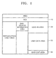
- the optical information storage medium according to various embodiments of the present invention is divided into a plurality of areas according to function. As shown in FIG. 1, the optical information storage medium according to an embodiment of the present invention includes a burst cutting area (BCA) 10, a lead-in area 20, a user data area 30 for storing user data, and a lead-out area 40, which are sequentially formed from the inner boundary to the outer boundary of the optical information storage medium.
- BCA burst cutting area
- the BCA 10 stores the serial number of an optical information storage medium, for example, an optical disk, or data identifying the BCA.
- the lead-in area 20 stores disk-related information, copy protection information, and the like. Examples of the disk-related information are information about the type of information storage medium, such as a recordable disk, a write-one disk, or a reproduction-only disk, information about the number of recording layers, information about a recording speed, information about the disk size, and the like.
- an optical information storage medium includes a first transition zone 15 between the BCA 10 and the lead-in area 20.
- the BCA 10 stores data recorded in a first straight pit pattern.
- the lead-in area 20 stores data that may be recorded in a second straight pit pattern, which is different from the first straight pit pattern, or in a wobbling pit pattern.
- the BCA 10 stores data recorded in a first wobbling pit pattern
- the lead-in area 20 stores data that may be recorded in a second wobbling pit pattern, which is different from the first wobbling pit pattern, or in a straight pit pattern.
- a straight pit pattern denotes an arrangement of pits along a straight line
- a wobbling pit pattern denotes an arrangement of pits along a wavy line.
- the first and second straight pit patterns and the first and second wobbling pit patterns may be classified as a single pattern, a specific pattern, or a random pattern.
- the single pattern denotes a pattern in which pits, each having an identical length (nT), are arranged at regular intervals.
- n denotes a natural number
- T denotes the minimum length of a pit.
- a straight single pit pattern denotes a pattern in which pits each having an identical length are arranged along a straight line.
- a wobbling single pit pattern denotes a pattern in which pits each having an identical length are arranged along a wavy line.
- the specific pattern denotes a repetition of a pattern of pits having different lengths.
- a pattern of a 3T pit and a 6T pit repeats.
- a straight specific pit pattern denotes a repetition of a pattern of pits that have different lengths along a straight line.
- a wobbling specific pit pattern denotes a repetition of a pattern of pits with different lengths along a wavy line.
- the random pattern denotes a random arrangement of pits having different lengths.
- a straight random pit pattern denotes a random arrangement of pits with different lengths along a straight line.
- a wobbling random pit pattern denotes a random arrangement of pits with different lengths along a wavy line.
- the first transition area 15 is included between the BCA 10 and the lead-in area 20 in order to prevent an improper consecutive reproduction of data.
- the first transition area 15 stores data identifying a transition area.
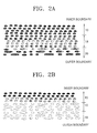
- FIG. 2A through 2E show examples of a pit pattern for the first transition area 15 when the BCA 10 is formed of pits in a straight single pattern and the lead-in area 20 is formed of pits in a straight random pattern.
- data is recorded in the BCA 10 in the form of a straight single pattern of pits
- data is recorded in the lead-in area 20 in the form of a straight random pattern of pits
- the first transition area 15 between the BCA 10 and the lead-in area 20 is formed of a straight single pattern of pits.
- the first transition area 15 may be formed of a wobbling single pattern of pits.
- data is recorded in the BCA 10 in the form of a straight single pattern of pits
- data is recorded in the lead-in area 20 in the form of a straight random pattern of pits
- the first transition area 15 between the BCA 10 and the lead-in area 20 is formed of a straight random pattern of pits.
- the first transition area 15 may be formed of a wobbling random pattern of pits.
- data is recorded in the BCA 10 in the form of a straight single pattern of pits
- data is recorded in the lead-in area 20 in the form of a straight random pattern of pits
- the first transition area 15 between the BCA 10 and the lead-in area 20 is a mirror area.
- data is recorded in the BCA 10 in the form of a straight single pattern of pits
- data is recorded in the lead-in area 20 in the form of a straight random pattern of pits
- the first transition area 15 between the BCA 10 and the lead-in area 20 is formed of a straight specific pattern of pits.
- the first transition area 15 may be formed of a wobbling single pattern of pits, a wobbling random pattern of pits, or a wobbling specific pattern of pits.
- the first transition area 15 is formed of a wobbling random pattern of pits.
- FIGS. 2A through 2E show the BCA 10 formed of a straight single pattern of pits, the BCA 10 may be formed of a wobbling single pattern of pits.
- FIGS. 3A through 3E show examples of a pit pattern for the first transition area 15 between the BCA 10 and the lead-in area 20 when the BCA 10 is formed of a straight specific pattern of pits and the lead-in area 20 is formed of a straight random pattern of pits.
- the first transition area 15 is formed of a straight single pattern of pits.
- the first transition area 15 is formed of a straight random pattern of pits.
- the first transition area 15 is a mirror area.
- the first transition area 15 is formed of a straight specific pattern of pits.
- the first transition area 15 is formed of a wobbling random pattern of pits.
- the first transition area 15 may be formed of a wobbling single pattern of pits, a wobbling random pattern of pits, or a wobbling specific pattern of pits.
- FIGS. 4A through 4E show examples of a pit pattern formed in the first transition area 15 between the BCA 10 and the lead-in area 20 when pits are formed in the BCA 10 in a straight random pattern and pits are formed in the lead-in area 20 in a straight random pattern.
- pits are formed in the first transition area 15 in a straight single pattern.
- FIG. 4B pits are formed in the first transition area 15 in a straight random pattern.
- the first transition area 15 is a mirror area.
- pits are formed in the first transition area 15 in a straight specific pattern.
- pits may be formed in the first transition area 15 in a wobbling single pattern, a wobbling random pattern, or a wobbling specific pattern.
- the first transition area 15 is formed of a wobbling random pattern of pits.
- pits may be formed in the BCA 10 in a wobbling random pattern instead of a straight random pattern.
- the BCA 10 may be formed of a wobbling pattern of pits.
- pits may be formed in the BCA 10 in a wobbling single pattern, in a wobbling specific pattern, or in a wobbling random pattern.
- Pits may be formed in the BCA 10 in a straight pattern or a wobbling pattern and pits are formed in the lead-in area 20 in a wobbling pattern.
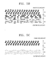
- FIGS. 5A through 5E show examples of a pit pattern formed in the first transition area 15 between the BCA 10 and the lead-in area 20 when pits are formed in the BCA 10 in a straight single pattern and pits are formed in the lead-in area 20 in a wobbling random pattern.
- FIG. 5A pits are formed in the first transition area 15 in a straight single pattern.
- FIG. 5B pits are formed in the first transition area 15 in a straight random pattern.
- the first transition area 15 is a mirror area.
- pits are formed in the first transition area 15 in a straight specific pattern.
- pits may be formed in the first transition area 15 in a wobbling single pattern, a wobbling random pattern, or a wobbling specific pattern.
- pits are formed in the first transition area 15 in a wobbling random pattern.
- FIGS. 5A through 5E show the BCA 10 where pits are formed in a straight single pattern, pits may be formed in the BCA 10 in a wobbling single pattern.
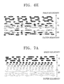
- FIGS. 6A through 6E show examples of a pit pattern formed in the first transition area 15 when pits are formed in the BCA 10 in a straight specific pattern and pits are formed in the lead-in area 20 in a wobbling random pattern.
- pits are formed in the first transition area 15 in a straight single pattern.
- FIG. 6B pits are formed in the first transition area 15 in a straight random pattern.
- FIG. 6C the first transition area 15 is a mirror area.
- pits are formed in the first transition area 15 in a straight specific pattern.
- pits may be formed in the first transition area 15 in a wobbling single pattern, a wobbling random pattern, or a wobbling specific pattern.
- FIG. 6E shows the first transition area 15 where pits are formed in a wobbling random pattern.
- FIGS. 6A through 6E show the BCA 10 where pits are formed in a straight specific pattern, pits may be formed in the BCA 10 in a wobbling specific pattern.
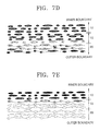
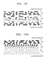
- FIGS. 7A through 7F show examples of a pit pattern formed in the first transition area 15 when pits are formed in the BCA 10 in a straight random pattern and pits are formed in the lead-in area 20 are formed in a wobbling random pattern.
- FIG. 7A pits are formed in the first transition area 15 in a straight single pattern.
- FIG. 7B pits are formed in the first transition area 15 in a straight random pattern.
- FIG. 7C the first transition area 15 is a mirror area.
- FIG. 7D pits are formed in the first transition area 15 in a straight specific pattern.
- pits may be formed in the first transition area 15 in a wobbling single pattern, a wobbling random pattern, or a wobbling specific pattern.
- FIG. 7E shows the first transition area 15 where pits are formed in a wobbling random pattern.
- FIGS. 7A through 7E show the BCA 10 where pits are formed in a straight random pattern
- pits may be formed in the BCA 10 in a wobbling random pattern.
- information containing a content such as, 00h or BCA, is recordable in the BCA 10.
- the first transition area 15, or the lead-in area 20 in a wobbling pattern are formed so that the amplitude of a wobble gradually increases or decreases.
- the pits are formed in the first transition area 15 in a wobbling pattern so that the amplitude of a wobble can gradually increase.
- the BCA 10, the first transition area 15, and the lead-in area 20 may have either an identical track pitch or different track pitches.
- the BCA 10 and the first transition area 15 have the same track pitch, and only the lead-in area 20 has a different track pitch.
- the first transition area 15 and the lead-in area 20 may have the same track pitch, and only the BCA 10 has a different track pitch.
- the first transition area 15 is formable so that its track pitch can gradually increase or decrease. For example, when a track pitch for the BCA 10 is "a" and a track pitch for the lead-in area 20 is "b" (b>a), the first transition area 15 is formed so that its track pitch can gradually increase from "a" to "b".
- An optical information storage medium includes the BCA 10, the lead-in area 20, the user data area 30, and the lead-out area 40.
- a second transition area 25 is further included between the lead-in area 20 and the user data area 30.
- the second transition area 25 are formable of a straight single pattern of pits, a straight specific pattern of pits, a straight random pattern of pits, a wobbling single pattern of pits, a wobbling specific pattern of pits, or a wobbling random pattern of pits.
- the second transition area 25 can be a mirror area.
- Each of the third and fourth straight patterns may be one of the straight single pattern, the straight specific pattern, and the straight random pattern.
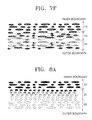
- FIGS. 8A through 8F show examples of a pit pattern formed in the second transition area 25 when pits are formed in the lead-in area 20 in a straight random pattern and pits are formed in the user data area 30 in a straight random pattern.
- pits are formed in the second transition area 25 in a straight single pattern.
- FIG. 8B pits are formed in the second transition area 25 in a straight random pattern.
- FIG. 8C the second transition area 25 is a mirror area.
- pits are formed in the second transition area 25 in a straight specific pattern.
- pits may be formed in the second transition area 25 in a wobbling single pattern, a wobbling random pattern, or a wobbling specific pattern.
- FIG. 8E shows the second transition area 25 where pits are formed in a wobbling random pattern.
- a pit pattern formed in the second transition area 25 when the lead-in area 25 is formed of a wobbling pattern of pits and the user data area 30 is formed of a straight pattern of pits will now be described.
- pits may be formed in the lead-in area 20 in a wobbling single pattern, a wobbling specific pattern, or a wobbling random pattern
- pits may be formed in the user data area 30 in a straight single pattern, a straight specific pattern, or a straight random pattern.
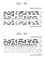
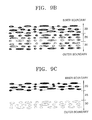
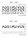
- FIGS. 9A through 9F show examples of a pit pattern formed in the second transition area 25 when the lead-in area 20 and the user data area 30 are formed of pits to have a wobbling random pattern and a straight random pattern, respectively.
- pits are formed in the second transition area 25 in a straight single pattern.
- FIG. 9B pits are formed in the second transition area 25 in a straight random pattern.
- FIG. 9C the second transition area 25 is a mirror area.
- pits are formed in the second transition area 25 in a straight specific pattern.
- pits may be formed in the second transition area 25 in a wobbling single pattern, a wobbling random pattern, or a wobbling specific pattern.
- FIG. 9E shows the second transition area 25 where pits are formed in a wobbling random pattern.
- Examples of a pit pattern formed in the second transition area 25 when the lead-in area 20 and the user data area 30 are formed of a straight pattern of pits and a wobbling pattern of pits, respectively, will now be described.
- pits may be formed in the lead-in area 20 in a straight single pattern, a straight specific pattern, or a straight random pattern
- pits may be formed in the user data area 30 in a wobbling single pattern, a wobbling specific pattern, or a wobbling random pattern.
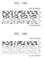
- FIGS. 10A through 10F show examples of a pit pattern formed in the second transition area 25 when the lead-in area 20 and the user data area 30 are formed of pits to have a straight random pattern and a wobbling random pattern, respectively.
- pits are formed in the second transition area 25 in a straight single pattern.
- FIG. 10B pits are formed in the second transition area 25 in a straight random pattern.
- FIG. 10C the second transition area 25 is a mirror area.
- pits are formed in the second transition area 25 in a straight specific pattern.
- pits may be formed in the second transition area 25 in a wobbling single pattern, a wobbling random pattern, or a wobbling specific pattern.
- FIG. 10E shows the second transition area 25 where pits are formed in a wobbling random pattern.
- the second transition area 25 included therebetween is formable of a straight single pattern of pits, a straight specific pattern of pits, a straight random pattern of pits, a wobbling single pattern of pits, a wobbling specific pattern of pits, or a wobbling random pattern of pits.
- the second transition area 25 can be a mirror area.
- the lead-in area 20, the second transition area 25, and the user data area 30 may have either an identical track pitch or different track pitches.
- the lead-in area 20 and the second transition area 25 have the same track pitch, and only the user data area 30 has a different track pitch.
- the second transition area 25 and the user data area 30 may have the same track pitch, and only the lead-in area 20 has a different track pitch.
- the second transition area 25 is formable so that its track pitch can gradually increase or decrease. For example, when a track pitch for the lead-in area 20 is "c" and a track pitch for the user data area 30 is "d" (d>c), the second transition area 25 is formed so that its track pitch can gradually increase from "c" to "d".
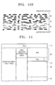
- An optical information storage medium according to a third embodiment of the present invention is divided into a plurality of areas, at least one of which is divided into a plurality of sub-areas according to function. A third transition area is included between two adjacent sub-areas.
- the optical information storage medium according to the third embodiment of the present invention includes the BCA 10, the lead-in area 20, the user data area 30, and the lead-out area 40.
- the lead-in area 20 includes first and second sub-areas 20a and 20b, respectively.
- a transition area may be included both between the BCA 10 and the lead-in area 20 and between the lead-in area 20 and the user data area 30.
- the principle of the first and second transition areas of the first and second embodiments is equally applied to these transition areas.
- a third transition area 27 is included between the first and second sub-areas 20a and 20b of the lead-in area 20.
- a pit pattern formed in each of the first and second sub-areas 20a and 20b and the third transition area 27 will be described in greater detail.
- the first and second sub-areas 20a and 20b are formed of pits in a straight pattern and a wobbling pattern, respectively.
- the straight pattern may be a straight single pattern, a straight specific pattern, or a straight random pattern
- the wobbling pattern may be a wobbling single pattern, a wobbling specific pattern, or a wobbling random pattern.
- the third transition area 27 formed between the first and second sub-areas 20a and 20b when the first and second sub-areas 20a and 20b are formed of pits to have a straight pattern and a wobbling pattern, respectively, will now be described.
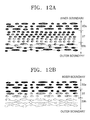
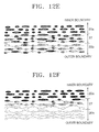
- FIGS. 12A through 12F show examples of a pit pattern for the third transition area 27 when the first and second sub-areas 20a and 20b are formed of pits to have a straight random pattern and a wobbling random pattern, respectively.
- pits are formed in the third transition area 27 in a straight single pattern.
- FIG. 12B pits are formed in the third transition area 27 in a straight random pattern.
- FIG. 12C the third transition area 27 is a mirror area.
- pits are formed in the third transition area 27 in a straight specific pattern.
- pits may be formed in the third transition area 27 in a wobbling single pattern, a wobbling random pattern, or a wobbling specific pattern.
- FIG. 12E shows the third transition area 27 where pits are formed in a wobbling random pattern.
- pits are formed in the third transition area 27 in a wobbling pattern, they are formable so that the amplitude of a wobble can gradually increase or decrease.
- the third transition area 27 is formable of a wobbling random pattern of pits so that the amplitude of a wobble can gradually increase as shown in FIG. 12F.
- the third transition area 27 included therebetween may be formed of a straight single pattern of pits, a straight specific pattern of pits, a straight random pattern of pits, a wobbling single pattern of pits, a wobbling specific pattern of pits, or a wobbling random pattern of pits.
- the third transition area 27 may be a mirror area.
- pits When pits are formed in the first and second sub-areas 20a and 20b and the third transition area 27 in a wobbling pattern, they may be formed so that the amplitude of a wobble gradually increases or decreases.
- the BCA 10, the user data area 30, or the lead-out area 40 may also be divided into a plurality sub-areas.
- a transition area may be formed between two adjacent sub-areas.
- the first and second sub-areas 20a and 20b and the third transition area 27 may have either an identical track pitch or different track pitches.
- the first sub-area 20a and the third transition area 27 have the same track pitch, and only the second sub-area 20b has a different track pitch.
- the third transition area 27 and the second sub-area 20b have the same track pitch, and only the first sub-area 20a has a different track pitch.
- the third transition area 27 may be formed so that its track pitch can gradually increase or decrease.
- the third transition area 27 is formed so that its track pitch can gradually increase from “e” to "f".
- the apparatus includes a recording/reading unit 100 and a controller 200.
- the recording/reading unit 100 writes data to and/or reproduces data from a write once recording medium 300 that is an information storage medium.
- an optical information storage medium includes a plurality of areas, and a transition area is included in at least one of boundary areas formed by the areas.
- a transition area is included in at least one of an area between the BCA 10 and the lead-in area 20, an area between the lead-in area 20 and the user data area 30, and an area between the first and second sub-areas 20a and 20b.
- a pit pattern formed in the transition area may be the same as that formed in the area that is in front of or at rear of the transition area.
- the area in front of the transition area denotes an area that is closer to the center of the storage medium than the transition area.
- the area at rear of the transition area denotes an area that is more outside than the transition area in the radial direction of the storage medium.
- the optical information storage medium according to the described embodiments of the present invention may be constituted with a single layer or a plurality of layers.
- the optical information storage medium according to the described embodiments of the present invention is divided into a plurality of areas according to function or purpose, and a transition area is included between two adjacent areas.
- a transition area is included between two adjacent areas.
- data is smoothly reproduced at a low error generation rate.
- the optical information storage medium according to the present invention provides standards for the transition area, it is compatible with existing optical information storage media.
Landscapes
- Engineering & Computer Science (AREA)
- Software Systems (AREA)
- Theoretical Computer Science (AREA)
- Optical Recording Or Reproduction (AREA)
- Signal Processing For Digital Recording And Reproducing (AREA)
- Optical Record Carriers And Manufacture Thereof (AREA)
Applications Claiming Priority (2)
| Application Number | Priority Date | Filing Date | Title |
|---|---|---|---|
| KR1020030006286A KR20040069750A (ko) | 2003-01-30 | 2003-01-30 | 광정보 저장 매체 |
| EP04706884A EP1588361A4 (fr) | 2003-01-30 | 2004-01-30 | Support memoire optique |
Related Parent Applications (1)
| Application Number | Title | Priority Date | Filing Date |
|---|---|---|---|
| EP04706884A Division EP1588361A4 (fr) | 2003-01-30 | 2004-01-30 | Support memoire optique |
Publications (2)
| Publication Number | Publication Date |
|---|---|
| EP1903565A2 true EP1903565A2 (fr) | 2008-03-26 |
| EP1903565A3 EP1903565A3 (fr) | 2008-10-08 |
Family
ID=36142210
Family Applications (6)
| Application Number | Title | Priority Date | Filing Date |
|---|---|---|---|
| EP04706884A Withdrawn EP1588361A4 (fr) | 2003-01-30 | 2004-01-30 | Support memoire optique |
| EP07120494A Withdrawn EP1903564A3 (fr) | 2003-01-30 | 2004-01-30 | Support optique de stockage d'information |
| EP07120495A Ceased EP1903565A3 (fr) | 2003-01-30 | 2004-01-30 | Support optique de stockage d'information |
| EP07120497A Withdrawn EP1906392A3 (fr) | 2003-01-30 | 2004-01-30 | Système optique de stockage d'information |
| EP07120498A Withdrawn EP1906393A3 (fr) | 2003-01-30 | 2004-01-30 | Système optique de stockage d'information |
| EP07120491A Ceased EP1903563A3 (fr) | 2003-01-30 | 2004-01-30 | Système optique de stockage d'information |
Family Applications Before (2)
| Application Number | Title | Priority Date | Filing Date |
|---|---|---|---|
| EP04706884A Withdrawn EP1588361A4 (fr) | 2003-01-30 | 2004-01-30 | Support memoire optique |
| EP07120494A Withdrawn EP1903564A3 (fr) | 2003-01-30 | 2004-01-30 | Support optique de stockage d'information |
Family Applications After (3)
| Application Number | Title | Priority Date | Filing Date |
|---|---|---|---|
| EP07120497A Withdrawn EP1906392A3 (fr) | 2003-01-30 | 2004-01-30 | Système optique de stockage d'information |
| EP07120498A Withdrawn EP1906393A3 (fr) | 2003-01-30 | 2004-01-30 | Système optique de stockage d'information |
| EP07120491A Ceased EP1903563A3 (fr) | 2003-01-30 | 2004-01-30 | Système optique de stockage d'information |
Country Status (13)
| Country | Link |
|---|---|
| US (8) | US7408870B2 (fr) |
| EP (6) | EP1588361A4 (fr) |
| JP (2) | JP4559408B2 (fr) |
| KR (1) | KR20040069750A (fr) |
| CN (2) | CN101042896B (fr) |
| CA (1) | CA2507829C (fr) |
| HK (1) | HK1108208A1 (fr) |
| MX (1) | MXPA05007098A (fr) |
| MY (2) | MY144131A (fr) |
| RU (2) | RU2314578C2 (fr) |
| SG (1) | SG157964A1 (fr) |
| TW (3) | TWI243370B (fr) |
| WO (1) | WO2004068478A1 (fr) |
Families Citing this family (14)
| Publication number | Priority date | Publication date | Assignee | Title |
|---|---|---|---|---|
| JP4101666B2 (ja) * | 2002-01-22 | 2008-06-18 | 松下電器産業株式会社 | 情報記録媒体、記録装置、再生装置、記録方法、再生方法 |
| KR20040069750A (ko) * | 2003-01-30 | 2004-08-06 | 삼성전자주식회사 | 광정보 저장 매체 |
| JP4170132B2 (ja) * | 2003-04-14 | 2008-10-22 | 松下電器産業株式会社 | 光記録媒体 |
| JP2006048772A (ja) * | 2004-07-30 | 2006-02-16 | Taiyo Yuden Co Ltd | 光情報記録媒体 |
| JP2006236421A (ja) | 2005-02-22 | 2006-09-07 | Toshiba Corp | 記憶媒体、再生方法及び記録方法 |
| JP4575211B2 (ja) * | 2005-03-31 | 2010-11-04 | 株式会社東芝 | 記憶媒体、再生方法及び記録方法 |
| JP4473768B2 (ja) | 2005-04-14 | 2010-06-02 | 株式会社東芝 | 情報記憶媒体、再生方法及び記録方法 |
| US20060274617A1 (en) * | 2005-06-03 | 2006-12-07 | Musto James J | Techniques for forming burst cutting area mark |
| JPWO2007010824A1 (ja) * | 2005-07-15 | 2009-01-29 | パイオニア株式会社 | 情報記録媒体、情報再生装置及び方法、並びに、情報記録媒体の製造装置及び方法 |
| JP2009283130A (ja) * | 2009-08-31 | 2009-12-03 | Toshiba Corp | 記憶媒体、再生方法及び記録方法 |
| JP2010267377A (ja) * | 2010-07-29 | 2010-11-25 | Toshiba Corp | 情報記憶媒体、再生方法、記録方法及び再生装置 |
| JP2010267378A (ja) * | 2010-07-29 | 2010-11-25 | Toshiba Corp | 情報記憶媒体、再生方法、記録方法及び再生装置 |
| JP2012190509A (ja) * | 2011-03-11 | 2012-10-04 | Hitachi Consumer Electronics Co Ltd | 光情報媒体、光情報記録再生装置及び光情報記録再生方法 |
| JP2012128945A (ja) * | 2012-04-02 | 2012-07-05 | Toshiba Corp | 記憶媒体、再生方法及び記録方法 |
Citations (1)
| Publication number | Priority date | Publication date | Assignee | Title |
|---|---|---|---|---|
| JPH06176367A (ja) | 1992-12-01 | 1994-06-24 | Hitachi Maxell Ltd | 光ディスク及び原盤記録装置 |
Family Cites Families (43)
| Publication number | Priority date | Publication date | Assignee | Title |
|---|---|---|---|---|
| US766958A (en) * | 1903-09-25 | 1904-08-09 | John A Lyons | Accumulator. |
| US776889A (en) * | 1904-04-08 | 1904-12-06 | Andrew V Cleland | Smut-machine. |
| US5283779A (en) * | 1990-04-20 | 1994-02-01 | Sony Corporation | Rewritable optical disc |
| JPH05258469A (ja) * | 1992-03-13 | 1993-10-08 | Sony Corp | 光ディスク記録媒体及び記録再生装置の動作制御方法 |
| JP3105070B2 (ja) * | 1992-04-27 | 2000-10-30 | パイオニアビデオ株式会社 | ディスク状記録媒体 |
| JP3240762B2 (ja) * | 1993-07-26 | 2001-12-25 | ソニー株式会社 | 光記録媒体の再生方法及び再生装置 |
| JPH09320205A (ja) | 1996-06-03 | 1997-12-12 | Highwits Technol Ltd | 光記録媒体 |
| JP3833329B2 (ja) | 1997-02-07 | 2006-10-11 | 株式会社リコー | 光情報記録媒体とそのデータ記録方法及び原盤露光方法 |
| JPH10293971A (ja) | 1997-04-18 | 1998-11-04 | Sanyo Electric Co Ltd | 光ディスク、ディスク再生装置およびディスク再生方法 |
| JPH11162114A (ja) * | 1997-11-28 | 1999-06-18 | Yamaha Corp | 光ディスク |
| JPH11167719A (ja) | 1997-12-04 | 1999-06-22 | Sanyo Electric Co Ltd | 光記録媒体およびその再生装置 |
| JP2000132850A (ja) | 1998-10-23 | 2000-05-12 | Pioneer Electronic Corp | 記録情報再生装置 |
| DE60011958T2 (de) * | 1999-04-28 | 2005-08-25 | Matsushita Electric Industrial Co., Ltd., Kadoma | Optische Platte, optisches Plattenaufzeichnungs- und wiedergabegerät, und Verfahren zur Aufzeichnung und Wiedergabe |
| JP2001014684A (ja) * | 1999-06-30 | 2001-01-19 | Toshiba Corp | 光ディスクおよびその製造方法 |
| US6661768B1 (en) * | 1999-10-13 | 2003-12-09 | Matsushita Electric Industrial Co., Ltd. | Optical disk, and method and apparatus for reproducing information recorded in optical disk |
| JP4277452B2 (ja) * | 2000-02-25 | 2009-06-10 | ソニー株式会社 | 記録装置、再生装置 |
| TW544671B (en) * | 2000-02-25 | 2003-08-01 | Sony Corp | Recording medium, recording apparatus, and reading apparatus |
| CN1193355C (zh) | 2000-05-17 | 2005-03-16 | 日本胜利株式会社 | 信息记录媒体及其记录方法 |
| JP2002063778A (ja) | 2000-08-18 | 2002-02-28 | Sony Corp | ディスクカートリッジおよびその製造方法ならびに記録再生システム |
| AU2001246913A1 (en) * | 2000-08-28 | 2002-03-13 | Nikon Corporation | Optical information recording medium, stamper, and method of manufacturing stamper |
| JP2002260243A (ja) * | 2000-08-30 | 2002-09-13 | Nikon Corp | 光情報記録媒体 |
| JP2002260241A (ja) * | 2000-08-30 | 2002-09-13 | Nikon Corp | 光情報記録媒体、スタンパー及びスタンパーの製造方法 |
| EP1577885A3 (fr) * | 2000-09-22 | 2007-12-12 | Matsushita Electric Industrial Co., Ltd. | Disque optique et procédé de reproduction, appareil de reproduction, et appareil d'enregistrement associé |
| BR0204490A (pt) * | 2001-03-19 | 2003-06-24 | Koninkl Philips Electronics Nv | Suporte de gravação, método e aparelho de gravação de informações e método de fabricação de um suporte de gravação |
| KR100727916B1 (ko) * | 2001-05-02 | 2007-06-13 | 삼성전자주식회사 | 광디스크 |
| JP2003016697A (ja) * | 2001-06-29 | 2003-01-17 | Nikon Corp | 光情報記録媒体、スタンパー及びスタンパーの製造方法 |
| KR100433521B1 (ko) * | 2001-08-04 | 2004-05-31 | 삼성전자주식회사 | 워블신호가 기록된 존 전이영역을 포함하는 정보기록매체, 그 기록장치 및 기록방법 |
| JP2003109258A (ja) | 2001-09-28 | 2003-04-11 | Sony Corp | 光記録媒体 |
| KR100716962B1 (ko) * | 2001-09-29 | 2007-05-10 | 삼성전자주식회사 | 광디스크 |
| JP4101666B2 (ja) * | 2002-01-22 | 2008-06-18 | 松下電器産業株式会社 | 情報記録媒体、記録装置、再生装置、記録方法、再生方法 |
| CN1295690C (zh) * | 2002-02-18 | 2007-01-17 | 皇家飞利浦电子股份有限公司 | 光记录介质和用于光记录介质的重放方法 |
| JP2005524192A (ja) * | 2002-05-01 | 2005-08-11 | エルジー エレクトロニクス インコーポレーテッド | 高密度再生専用光ディスクとそれによる光ディスク装置及び方法 |
| KR20030092588A (ko) * | 2002-05-30 | 2003-12-06 | 삼성전자주식회사 | 광정보 저장매체 및 그 기록/재생 방법 |
| US7342871B2 (en) * | 2002-05-30 | 2008-03-11 | Lg Electronics Inc. | High density optical disc and method for reproducing and recording data thereof |
| KR100881665B1 (ko) * | 2002-05-31 | 2009-02-06 | 삼성전자주식회사 | 다층의 광 정보 저장매체 및 그 기록/재생 방법 |
| KR20040001596A (ko) | 2002-06-28 | 2004-01-07 | 삼성전자주식회사 | 재생전용 고밀도 광디스크 및 그 재생 방법 |
| US20040013067A1 (en) * | 2002-06-29 | 2004-01-22 | Samsung Electronics Co., Ltd. | Information storage medium and method of recording and/or reproducing data thereon |
| US7649824B2 (en) * | 2002-07-01 | 2010-01-19 | Panasonic Corporation | Optical storage medium control data region |
| KR20040016536A (ko) * | 2002-08-17 | 2004-02-25 | 엘지전자 주식회사 | 고밀도 재생 전용 광디스크의 어드레스 정보 기록방법과,그에 따른 고밀도 재생 전용 광디스크 |
| KR100576160B1 (ko) * | 2002-12-11 | 2006-05-03 | 엘지전자 주식회사 | 고밀도 광디스크의 기록위치 판별방법 및 장치 |
| KR20040069750A (ko) * | 2003-01-30 | 2004-08-06 | 삼성전자주식회사 | 광정보 저장 매체 |
| US20050207293A1 (en) * | 2004-03-16 | 2005-09-22 | Kim Jin Y | Recording medium and method for recording and reproducing data on and from the same |
| JP2005285153A (ja) * | 2004-03-26 | 2005-10-13 | Toshiba Corp | 情報記録媒体、情報再生装置、情報再生方法、および情報記録方法 |
-
2003
- 2003-01-30 KR KR1020030006286A patent/KR20040069750A/ko active Search and Examination
-
2004
- 2004-01-30 EP EP04706884A patent/EP1588361A4/fr not_active Withdrawn
- 2004-01-30 WO PCT/KR2004/000170 patent/WO2004068478A1/fr active Application Filing
- 2004-01-30 TW TW093102104A patent/TWI243370B/zh not_active IP Right Cessation
- 2004-01-30 EP EP07120494A patent/EP1903564A3/fr not_active Withdrawn
- 2004-01-30 CN CN2007101044187A patent/CN101042896B/zh not_active Expired - Lifetime
- 2004-01-30 RU RU2005120663/28A patent/RU2314578C2/ru active
- 2004-01-30 US US10/766,889 patent/US7408870B2/en active Active
- 2004-01-30 TW TW093102102A patent/TWI309819B/zh not_active IP Right Cessation
- 2004-01-30 EP EP07120495A patent/EP1903565A3/fr not_active Ceased
- 2004-01-30 MX MXPA05007098A patent/MXPA05007098A/es active IP Right Grant
- 2004-01-30 MY MYPI20040283A patent/MY144131A/en unknown
- 2004-01-30 JP JP2006502693A patent/JP4559408B2/ja not_active Expired - Lifetime
- 2004-01-30 EP EP07120497A patent/EP1906392A3/fr not_active Withdrawn
- 2004-01-30 MY MYPI20040284A patent/MY142563A/en unknown
- 2004-01-30 EP EP07120498A patent/EP1906393A3/fr not_active Withdrawn
- 2004-01-30 EP EP07120491A patent/EP1903563A3/fr not_active Ceased
- 2004-01-30 SG SG200705545-2A patent/SG157964A1/en unknown
- 2004-01-30 RU RU2007105668/28A patent/RU2421831C2/ru active
- 2004-01-30 CN CNB2004800016080A patent/CN100550143C/zh not_active Expired - Lifetime
- 2004-01-30 CA CA2507829A patent/CA2507829C/fr not_active Expired - Lifetime
- 2004-01-30 US US10/766,958 patent/US7339880B2/en active Active
- 2004-01-30 US US10/766,959 patent/US7382714B2/en active Active
- 2004-01-30 TW TW093102103A patent/TWI298877B/zh not_active IP Right Cessation
-
2006
- 2006-04-13 HK HK08102135.4A patent/HK1108208A1/xx not_active IP Right Cessation
- 2006-09-27 US US11/527,685 patent/US8427931B2/en active Active
-
2008
- 2008-02-01 US US12/024,158 patent/US7542392B2/en not_active Expired - Lifetime
- 2008-02-01 US US12/024,150 patent/US7551543B2/en not_active Expired - Lifetime
- 2008-02-08 JP JP2008029248A patent/JP4559495B2/ja not_active Expired - Lifetime
- 2008-04-03 US US12/061,759 patent/US20080186825A1/en not_active Abandoned
- 2008-06-24 US US12/144,754 patent/US7843798B2/en not_active Expired - Lifetime
Patent Citations (1)
| Publication number | Priority date | Publication date | Assignee | Title |
|---|---|---|---|---|
| JPH06176367A (ja) | 1992-12-01 | 1994-06-24 | Hitachi Maxell Ltd | 光ディスク及び原盤記録装置 |
Non-Patent Citations (2)
| Title |
|---|
| "The Standard ECMA-267", April 2001 |
| ECMA: STANDARDIZING INFORMATION AND COMMUNICATION SYSTEMS: "Standard ECMA-330: 120 mm (4,7 Gbytes per side) and 80 mm (1,46 Gbytes per side) DVD Rewritable Disk (DVD-RAM)", 1 December 2001 (2001-12-01), pages 1 - 142 * |
Also Published As
Similar Documents
| Publication | Publication Date | Title |
|---|---|---|
| US7551543B2 (en) | Optical information storage medium having a transition area provided between first area and second area of lead-in area and reproducing and/or recording apparatus for use therewith | |
| US8130619B2 (en) | Method of recording information to and reproducing information from an optical information storage medium | |
| KR100917891B1 (ko) | 광정보 저장 매체 및 정보 재생/기록 방법 | |
| KR100813990B1 (ko) | 광정보 저장 매체 및 정보 재생 방법 | |
| KR100917892B1 (ko) | 광정보 저장 매체 및 정보 재생/기록 방법 | |
| KR100917890B1 (ko) | 광정보 저장 매체 및 정보 재생/기록 장치 | |
| KR100924778B1 (ko) | 광정보 저장 매체 및 정보 재생/기록 장치 | |
| KR100772419B1 (ko) | 광정보 저장 매체 및 정보 재생 방법 |
Legal Events
| Date | Code | Title | Description |
|---|---|---|---|
| PUAI | Public reference made under article 153(3) epc to a published international application that has entered the european phase |
Free format text: ORIGINAL CODE: 0009012 |
|
| 17P | Request for examination filed |
Effective date: 20071112 |
|
| AC | Divisional application: reference to earlier application |
Ref document number: 1588361 Country of ref document: EP Kind code of ref document: P |
|
| AK | Designated contracting states |
Kind code of ref document: A2 Designated state(s): AT BE BG CH CY CZ DE DK EE ES FI FR GB GR HU IE IT LI LU MC NL PT RO SE SI SK TR |
|
| AX | Request for extension of the european patent |
Extension state: AL BA HR MK YU |
|
| PUAL | Search report despatched |
Free format text: ORIGINAL CODE: 0009013 |
|
| AK | Designated contracting states |
Kind code of ref document: A3 Designated state(s): AT BE BG CH CY CZ DE DK EE ES FI FR GB GR HU IE IT LI LU MC NL PT RO SE SI SK TR |
|
| AX | Request for extension of the european patent |
Extension state: AL BA HR MK RS |
|
| 17Q | First examination report despatched |
Effective date: 20090113 |
|
| AKX | Designation fees paid |
Designated state(s): AT BE BG CH CY CZ DE DK EE ES FI FR GB GR HU IE IT LI LU MC NL PT RO SE SI SK TR |
|
| STAA | Information on the status of an ep patent application or granted ep patent |
Free format text: STATUS: THE APPLICATION HAS BEEN REFUSED |
|
| 18R | Application refused |
Effective date: 20100427 |