EP1903544B1 - Verfahren zur Korrektur des Übersprechens in Flüssigkristallanzeigen - Google Patents
Verfahren zur Korrektur des Übersprechens in Flüssigkristallanzeigen Download PDFInfo
- Publication number
- EP1903544B1 EP1903544B1 EP06121078A EP06121078A EP1903544B1 EP 1903544 B1 EP1903544 B1 EP 1903544B1 EP 06121078 A EP06121078 A EP 06121078A EP 06121078 A EP06121078 A EP 06121078A EP 1903544 B1 EP1903544 B1 EP 1903544B1
- Authority
- EP
- European Patent Office
- Prior art keywords
- intensity
- pixels
- image
- primary
- intensity values
- Prior art date
- Legal status (The legal status is an assumption and is not a legal conclusion. Google has not performed a legal analysis and makes no representation as to the accuracy of the status listed.)
- Active
Links
Images



Classifications
-
- G—PHYSICS
- G09—EDUCATION; CRYPTOGRAPHY; DISPLAY; ADVERTISING; SEALS
- G09G—ARRANGEMENTS OR CIRCUITS FOR CONTROL OF INDICATING DEVICES USING STATIC MEANS TO PRESENT VARIABLE INFORMATION
- G09G3/00—Control arrangements or circuits, of interest only in connection with visual indicators other than cathode-ray tubes
- G09G3/20—Control arrangements or circuits, of interest only in connection with visual indicators other than cathode-ray tubes for presentation of an assembly of a number of characters, e.g. a page, by composing the assembly by combination of individual elements arranged in a matrix no fixed position being assigned to or needed to be assigned to the individual characters or partial characters
- G09G3/34—Control arrangements or circuits, of interest only in connection with visual indicators other than cathode-ray tubes for presentation of an assembly of a number of characters, e.g. a page, by composing the assembly by combination of individual elements arranged in a matrix no fixed position being assigned to or needed to be assigned to the individual characters or partial characters by control of light from an independent source
- G09G3/36—Control arrangements or circuits, of interest only in connection with visual indicators other than cathode-ray tubes for presentation of an assembly of a number of characters, e.g. a page, by composing the assembly by combination of individual elements arranged in a matrix no fixed position being assigned to or needed to be assigned to the individual characters or partial characters by control of light from an independent source using liquid crystals
- G09G3/3611—Control of matrices with row and column drivers
-
- G—PHYSICS
- G06—COMPUTING OR CALCULATING; COUNTING
- G06F—ELECTRIC DIGITAL DATA PROCESSING
- G06F3/00—Input arrangements for transferring data to be processed into a form capable of being handled by the computer; Output arrangements for transferring data from processing unit to output unit, e.g. interface arrangements
- G06F3/14—Digital output to display device ; Cooperation and interconnection of the display device with other functional units
- G06F3/147—Digital output to display device ; Cooperation and interconnection of the display device with other functional units using display panels
-
- G—PHYSICS
- G09—EDUCATION; CRYPTOGRAPHY; DISPLAY; ADVERTISING; SEALS
- G09G—ARRANGEMENTS OR CIRCUITS FOR CONTROL OF INDICATING DEVICES USING STATIC MEANS TO PRESENT VARIABLE INFORMATION
- G09G2320/00—Control of display operating conditions
- G09G2320/02—Improving the quality of display appearance
- G09G2320/0209—Crosstalk reduction, i.e. to reduce direct or indirect influences of signals directed to a certain pixel of the displayed image on other pixels of said image, inclusive of influences affecting pixels in different frames or fields or sub-images which constitute a same image, e.g. left and right images of a stereoscopic display
-
- G—PHYSICS
- G09—EDUCATION; CRYPTOGRAPHY; DISPLAY; ADVERTISING; SEALS
- G09G—ARRANGEMENTS OR CIRCUITS FOR CONTROL OF INDICATING DEVICES USING STATIC MEANS TO PRESENT VARIABLE INFORMATION
- G09G2320/00—Control of display operating conditions
- G09G2320/02—Improving the quality of display appearance
- G09G2320/0271—Adjustment of the gradation levels within the range of the gradation scale, e.g. by redistribution or clipping
Definitions
- the invention described herein generally relates to computer image analysis and processing.
- the invention relates to a method and apparatus for reducing cross-talk on a liquid crystal display.
- the conventional colour liquid crystal display includes a liquid crystal layer, and a semitransparent metal oxide layer (typically Indium Tin Oxide) that covers the liquid crystal layer. These two layers are sandwiched between two transparent substrates, which are typically provided as glass or plastic plates.
- a semitransparent metal oxide layer typically Indium Tin Oxide
- one of the transparent substrates includes a series of parallel data electrodes
- the other transparent substrates includes a series of parallel scanning electrodes that are arranged at a right angle to the data electrodes.
- the pixels are addressed by applying a pulse to the associated data electrode, while grounding the associated scanning electrode.
- one of the transparent substrates includes a matrix of thin-film transistors and storage capacitors.
- the display includes a transistor for each pixel in the display.
- the gate electrodes of the transistors in each row are connected together via a common scanning electrode, and the source electrodes of the transistors in each column are connected to a respective source driver.
- the pixels can be individually addressed by pulsing the scanning electrodes sequentially, and by applying the appropriate voltage signals to the data lines.
- the storage capacitors maintain the voltage applied to each pixel until the next voltage signal is applied.
- the optical transmittance of the display changes as the liquid crystal moves in response to the voltage applied to each corresponding section of the metal oxide layer. Therefore, the opacity of each pixel can be controlled via the voltage applied to the scanning and data electrodes.
- Cross-talk is a problem experienced with some liquid crystal displays in which the voltage applied to pixels on one part of the display influences the transmittance of the liquid crystal on pixels on other parts of the display. This problem is a result of several factors, including parasitic capacitance between the source and gate lines, and voltage drops due to the resistance of the metal oxide layer. As a result, cross-talk is particularly apparent when the display is rendering an image comprising a large bright (white) area on a dark (black or grey) background, or vice versa. In these cases, the bright area appears to bleed into the dark area, or vice versa.
- Howard (US 4,845,482 ) describes applying gating signals to the scanning electrodes for a shorter than normal interval, applying the data signal to the data electrodes during this shorter interval, and applying a compensation signal to the data electrodes during the remainder of the normal interval.
- Choi (US 5,774,103 ) describes driving the data electrodes from +Vd to -Vd through an intermediate voltage level.
- Bitzakidis (US 5,798,740 ) and Kawamori ( US 5,691,739 ) describe applying a compensation voltage to the data signal applied to each column electrode.
- Bitzakidis bases the compensation voltage on the capacitance of the transistors and the values for all the pixels in the same column.
- Kawamori bases the compensation voltage on the number of polarity inversions during each display period.
- Bassetti (US5,670,973 ) describes applying boost voltages to the row and column electrodes in proportion to the number of ON pixels in a row or column, the number of adjacent ON-OFF and OFF-ON pixel pairs in each column, and the position of each such pixel in each row.
- Murata (US 2004/0239587 ) describes, for each scan line, determining the average pixel value for the scan line, and then, for each pixel on the scan line, calculating the difference between each pixel value and the calculated average.
- the difference figures are input into a correction level determining unit that generates correction values based on the difference figures and a non-linear correction function.
- the correction values are then input into a correction unit that adjusts the value of each pixel based on the corresponding correction value.
- Fig. 6 of the patent application depicts a white box surrounded by gray space, and the adjusted pixel values for each pixel on the scan line.
- the pixel values for the gray space to the left and right of the white box are increased by the correction value (a), while the pixel values for the white box remain unchanged.
- the line B-B' extending through the gray space below the white box the pixel values for the entire line remain unchanged thereby creating the possibility of a visual discontinuity between the gray space above/below the box and the gray space to the left/right of the box.
- a method for reducing cross-talk on a liquid crystal display comprising the steps as defined in claim 1.
- a handheld computing device according to claim 7.
- a computer readable medium carrying processing instructions for a computer which, when executed; cause the computer to implement a method according to claim 1.
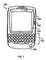
- the handheld computing device 100 includes a display 122, a function key 146, and data processing means 102 (not shown) disposed within a common housing.
- the display 122 comprises a backlit display having a variable-intensity backlight.
- the backlit display 122 comprises a transmissive LCD display, and the function key 146 operates as a power on/off switch.
- the backlit display 122 comprises a reflective or trans-reflective LCD display, and the function key 146 operates as a backlight switch.
- the data processing means 102 of the handheld computing device 100 is in communication with the display 122 and the function key 146.
- the handheld computing device 100 includes user data input means for inputting data to the data processing means 102.
- the user data input means includes a keyboard 132, a thumbwheel 148 and an escape key 160.
- the data processing means 102 comprises a microprocessor 138, and a memory 124, 126 (disposed within the housing).
- the memory 124, 126 computer processing instructions which, when accessed from the memory 124, 126 and executed by the microprocessor 138, implement an operating system, which includes a display processor 200.
- the memory 126 includes a frame buffer 202 which the display processor uses to render images on the display 122.
- the computer processing instructions provide the display processor 200 with the functionality of a pixel mapping means 204, a line identifying means 206, a scaling means 208 and an imaging means 210.
- the function of the pixel mapping means 204, the line identifying means 206, the scaling means 208 and the imaging means 210 will be discussed in greater detail below.
- the pixel mapping means 204, the line identifying means 206, the scaling means 208 and the imaging means 210 configure the display processor 200 with a method that reduces cross-talk on the display 122.
- the display processor 200 is preferably implemented as a set of computer processing instructions, the display processor 200 may be implemented in electronics hardware instead.
- the handheld computing device 100 is a two-way wireless communication device having at least voice and data communication capabilities. Further, preferably the handheld computing device 100 has the capability to communicate with other computer systems on the Internet. Depending on the exact functionality provided, the wireless handheld computing device 100 may be referred to as a data messaging device, a two-way pager, a wireless e-mail device, a cellular telephone with data messaging capabilities, a wireless Internet appliance, or a data communication device, as examples.
- Fig. 3 depicts functional details of the handheld computing device 100.
- the handheld computing device 100 sends and receives communication signals over the network 119, and comprises a motherboard that includes a communication subsystem 111, a microprocessor 138, and a SIM/RUIM interface 144.
- the communication subsystem 111 performs communication functions, such as data and voice communications, and includes a receiver 112, a transmitter 114, and associated components such as one or more embedded or internal, antenna elements 116 and 118, local oscillators (LOs) 113, and a processing module such as a digital signal processor (DSP) 120.
- DSP digital signal processor
- Signals received by antenna 116 through communication network 119 are input to the receiver 112, which performs common receiver functions such as frequency down conversion, and analog to digital (A/D) conversion, in preparation for more complex communication functions performed by the DSP 120.
- signals to be transmitted are processed by DSP 120 and input to transmitter 114 for digital to analog conversion, frequency up conversion, and transmission over the communication network 119 via antenna 118.
- the SIM/RUIM interface 144 is similar to a card-slot into which a SIM/RUIM card can be inserted and ejected like a diskette or PCMCIA card.
- the SIM/RUIM card holds many key configuration 151, and other information 153 such as identification, and subscriber related information.
- the microprocessor 138 controls the overall operation of the device, interacting with device subsystems such as the display 122, flash memory 124, random access memory (RAM) 126, auxiliary input/output (I/O) subsystems 128, serial port 130, keyboard 132, speaker 134, microphone 136, short-range communications subsystem 140, and device subsystems 142.
- the flash memory 124 includes both computer program storage 158 and program data storage 150, 152, 154 and 156.
- the RAM 126 includes a frame buffer 202 which the display processor 200 uses to render images on the display 122.
- Computer processing instructions are preferably also stored in the flash memory 124 or other similar non-volatile storage. Other computer processing instructions may also be loaded into a volatile memory such as RAM 126.
- the computer processing instructions when accessed from the flash memory 124 and the RAM 126 and executed by the microprocessor 138, define operating system software, computer programs, and operating system specific applications such as the display processor 200.
- Such computer programs may be installed onto the handheld computing device 100 upon manufacture, or may be loaded through the network 119, the auxiliary I/O subsystem 128, the serial port 130, the short-range communications subsystem 140, or device subsystem 142.
- a received text message or web page download will be processed by the communication subsystem 111 and output to the display 122, or alternatively to an auxiliary I/O device 128.
- a user of the handheld computing device 100 may compose data items such as email messages for example, using the keyboard 132. Such composed items may then be transmitted over a communication network through the communication subsystem 111.
- the handheld computing device 100 For voice communications, overall operation of the handheld computing device 100 is similar, except that received signals would preferably be output to a speaker 134 and signals for transmission would be generated by a microphone 136. Further, the display 122 may provide an indication of the identity of a calling party, the duration of a voice call, or other voice call related information for example.
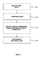
- Fig. 4 is a flow chart that depicts, by way of overview, the sequence of steps performed by the display processor 200 according to the invention.
- the display processor 200 receives pixel data defining an image comprising a plurality of pixels.
- the received pixel data includes an intensity value associated with each pixel.
- the display processor 200 compresses the image by reducing the range of the intensity values of all the pixels in the image. This step involves arithmetically adjusting the intensity values of the pixels so that the range of the intensity values of the pixels fall within a desired range.
- the display processor 200 identifies lines in the compressed image that are disposed to create cross-talk. Then, at step 406, the display processor 200 decompresses the compressed image by applying a scale factor to the adjusted intensity value associated only with the pixels in the identified lines. The scale factor is selected such that a display image that is rendered on the display from the pixel data of the decompressed image will have less cross-talk than a display image rendered on the liquid crystal display from the pixel data received at step 400.
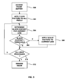
- Fig. 5 is a flow chart that depicts, in detail, the sequence of steps performed by the display processor 200.
- the display processor 200 accesses the frame buffer 202 which contains pixel data defining an image to be rendered on the display 122.
- the image comprises a plurality of pixels, and the pixel data includes an intensity value for each pixel.
- the intensity values of the pixels in the image have a primary maximum possible range that extends between a primary minimum intensity value and a primary maximum intensity value.
- the primary maximum possible range will depend on the number of data bits used to define the intensity of each pixel.
- the display processor 200 After accessing the pixel data, the display processor 200 arithmetically adjusts the intensity values of the pixels so that the intensity values of all the pixels fall within a secondary maximum possible range that is smaller than the primary maximum possible range. To do so, at step 502, the pixel mapping means 204 applies a gain factor to the intensity value of each pixel in the image.
- the range of the intensity values of all the pixels extends between a secondary minimum intensity value and a secondary maximum intensity value.
- the gain factors are selected so that the secondary minimum intensity value is greater than the primary minimum intensity value, but the secondary maximum intensity value is less than the primary maximum intensity value. Further, preferably the gain factors vary linearly over the primary maximum possible range of the pixel intensity values.
- Reference numeral 600 indicates the maximum possible range of the pixel intensity values at step 500. As shown, eight (8) data bits are used to define the intensity of each pixel, so that the primary minimum intensity value is 0, the primary maximum intensity value is 255, and the primary maximum possible range of the pixel intensity values is 0:255.
- Reference numeral 602 indicates the maximum possible range of the pixel intensity values after application of the gain factors.
- the secondary minimum intensity value is 20
- the secondary maximum intensity value is 235
- the secondary maximum possible range of the pixel intensity values is 20:235.
- the gain factor is +20 for a primary pixel intensity value of 0; -20 for a primary pixel intensity value of 255; and 0 for a primary pixel intensity value of 128.
- the gain factors vary linearly between +20 and -20 over the primary maximum possible range (0:255) of the pixel intensity values.
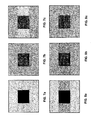
- Figs. 7a, 7b, 8a and 8b The effect of step 502 on the pixel data is depicted in Figs. 7a, 7b, 8a and 8b.
- Fig. 7a represents the contents of the frame buffer 202 at step 500
- Fig. 8a represents the image (the "primary image") that would be rendered on the display 122 from the contents of the frame buffer 202 as at step 500.
- the pixel data in the frame buffer 202 is configured to render on the display 122 a black square on a light grey background.
- the pixel data image would produce cross-talk on the display 122.
- Fig. 8a indicates that the primary image would be depicted with horizontal cross-talk, depending on the characteristics of the display 122, the primary image could also be depicted with vertical cross-talk.
- Fig. 7b represents the contents of the frame buffer 202 at step 502
- Fig. 8b represents the image (the "secondary image") that would be rendered on the display 122 from the contents of the frame buffer 202 as at step 502.
- the intensity values for all the pixel data in the frame buffer 202 are compressed, such that the range of intensity values of the pixels in the secondary image is smaller than the range of intensity values of the pixels in the primary image.
- the black square would appear to be lighter (less black) in the secondary image than in the primary image, and the light grey background would appear to be (less white) in the secondary image than in the primary image.
- the display processor 200 then identifies lines in the compressed image that are disposed to create cross-talk. To do so, at step 504 the line identifying means 206 determines the black content for each line in the secondary image. Typically, the line identifying means 206 determines the black content by calculating the average intensity level for all the pixels in each line.
- the line identifying means 206 will determine the black content for each horizontal line. However, the identifying means 206 can also be configured to determine the black content for each vertical line if the display 122 is predisposed to vertical cross-talk.
- the line identifying means 206 compares the determined black content for the current line of the secondary image against a predetermined threshold. If the determined black content for the current line is greater than the predetermined threshold, at step 508 the scaling means 208 applies a scale factor to the intensity values for the pixels in the current line. However, if the determined black content for the current line is not greater than the predetermined threshold, the scaling means 208 does not apply any scale factor to the current line.
- the display processor 200 determines whether all lines of the image have been analyzed. If additional lines remain to be analyzed, processing returns to step 504. However, if all lines of the image have been analyzed, at step 512 the imaging means 210 renders the image on the display 122 from the resulting pixel intensity data.
- the scale factors applied in step 508 are selected such that the rendered image will have less cross-talk than would a display image rendered on the display 122 from the pixel data of the primary image.
- the scale factors are selected such that the intensity values of all the pixels in the lines identified at step 506 (lines that are disposed to create cross-talk) occupy a larger intensity range than the range resulting from the application of the gain factors at step 502.
- the intensity values of all the pixels in the lines identified at step 506 also occupy a narrower intensity range than in the primary image.
- the scale factors vary linearly over the intensity range of the pixels of the secondary image between a minimum adjustment value and a maximum adjustment value.
- the pixels that are associated with the colour black on lines having high black content are least prone to cross-talk, whereas the pixels that are associated with the colour white on lines having high black content are most prone to cross-talk.
- the minimum and maximum adjustment values are selected such that the intensity values of the pixels that are associated with the colour black on lines having high black content receive a minimal adjustment, whereas the intensity values of the pixels that are associated with the colour white on lines having high black content receive the largest adjustment.
- Reference numeral 602 indicates the maximum possible range of the pixel intensity values after application of the gain factors at step 508. As shown, the secondary minimum intensity value is 20, the secondary maximum intensity value is 235, and the secondary maximum possible range of the pixel intensity values is 20:235.
- Reference numeral 604 indicates the maximum possible range of the pixel intensity values after application of the scale factors.
- the final minimum intensity value is equal to the secondary minimum intensity value (20).
- the final maximum intensity value is 249, which is greater than the secondary maximum intensity value (235) but less than the primary maximum intensity value (255). Therefore, the final maximum possible range of the pixel intensity values is 20:249.
- the scale factor is 0 for a secondary pixel intensity value of 0; and +14 for a secondary pixel intensity value of 235.
- the scale factors vary linearly between 0 and +14 over the final maximum possible range (20:249) of the pixel intensity values.
- Figs. 7c and 8c represent the contents of the frame buffer 202 after step 508, and Fig. 8c represents the image rendered on the display 122 from the contents of the frame buffer 202 as at step 508.
- Fig. 7c after application of the scale factors, the intensity values of the pixels in the lines identified in step 506 that correspond to grey background are increased above the intensity values of those pixels in the secondary image, but not back to the original intensity values those pixels had in the primary image.
- the intensity values of the pixels in the lines identified in step 506 that correspond to the black square remain unchanged. Further, the intensity values for the pixels in the lines not identified in step 506 also remain unchanged.
- decompressing step 508 increases the intensity of the pixels most prone to cross-talk.
- Compressing step 502 reduces the dynamic range of the pixel intensity of all the pixels in the image, to thereby allow the intensity of the pixels most prone to cross-talk to be increased.
- the imaging means 210 renders the final image on the display 122 from the resulting pixel intensity data
- the grey background on the horizontal lines containing the black square appears to have the same intensity as the grey background on the horizontal lines above and below the black square.
Landscapes
- Engineering & Computer Science (AREA)
- Chemical & Material Sciences (AREA)
- Crystallography & Structural Chemistry (AREA)
- Physics & Mathematics (AREA)
- Computer Hardware Design (AREA)
- General Physics & Mathematics (AREA)
- Theoretical Computer Science (AREA)
- Control Of Indicators Other Than Cathode Ray Tubes (AREA)
- Liquid Crystal Display Device Control (AREA)
Claims (13)
- Verfahren zum Reduzieren von Übersprechen bzw. Cross-Talk auf einer Flüssigkristallanzeige, das die Schritte aufweist:Zuordnen von Pixeldaten eines primären Bilds zu Pixeldaten eines sekundären Bilds, wobei die primären und sekundären Bilder jeweils eine Vielzahl von Pixeln aufweisen, die durch die jeweiligen Pixeldaten definiert sind, wobei die Pixeldaten Intensitätswerte für jeden dieser Pixel aufweisen,wobei das Zuordnen von Pixeldaten aufweist ein Anwenden eines Gain- bzw. Leuchtdichte-Faktors auf die Intensitätswerte der Pixel des primären Bilds, wobei ein Bereich der Intensitätswerte der Pixel des sekundären Bilds kleiner ist als ein Bereich der Intensitätswerte der Pixel des primären Bilds;Identifizieren von Linien in dem sekundären Bild, die angeordnet sind, um Cross-Talk zu erzeugen, wobei das Identifizieren von Linien aufweist, für jede Linie in dem sekundären Bild, Berechnen eines Durchschnittsintensitätswerts für alle Pixel in der Linie und Vergleichen des berechneten Durchschnittsintensitätswerts mit einem vorgegebenen Schwellenwert, wobei in jeder identifizierten Linie der zugehörige Durchschnittsintensitätswert größer ist als der vorgegebene Schwellenwert; undAnpassen der Intensitätswerte der Pixel in den identifizierten Linien derart, dass ein Anzeigebild, das auf einer Flüssigkristallanzeige gerendert wird, das aus dem Anpassen der Pixelintensität resultiert, weniger Cross-Talk hat als wenn aus den Pixeldaten des primären Bilds gerendert, wobei das Anpassen der Pixelintensität aufweist ein Anwenden eines jeweiligen Skalierungsfaktors auf den Intensitätswert jedes Pixels in der identifizierten Pixellinie, wobei der Skalierungsfaktor ein Minimum-Anpassungswert ist für die Pixel am wenigsten anfällig für Cross-Talk, ein Maximum-Anpassungswert ist für die Pixel am meisten anfällig für Cross-Talk und ansonsten eine variable Anpassung ist zwischen dem Minimum-Anpassungswert und dem Maximum-Anpassungswert, bestimmt basierend auf dem Intensitätswert des jeweiligen Pixels.
- Verfahren gemäß Anspruch 1, wobei die Intensitätswerte der Pixel des sekundären Bilds zwischen einer sekundären Minimum-Intensität und einer sekundären Maximum-Intensität sind und die Skalierungsfaktoren derart gewählt sind, dass für die Pixel in den identifizierten Linien die Intensitätswerte nahe der sekundären Maximum-Intensität mit einer größeren Anpassung vorgesehen sind als die Intensitätswerte nahe der sekundären Minimum-Intensität.
- Verfahren gemäß Anspruch 2, wobei ein Bereich der Intensitätswerte der Pixel der identifizierten Linien des gerenderten Bilds größer ist als ein Bereich der Intensitätswerte der Pixel der entsprechenden Linien des sekundären Bilds, aber kleiner als ein Bereich der Intensitätswerte der Pixel der entsprechenden Linien des primären Bilds.
- Verfahren gemäß Anspruch 3, wobei die variable Anpassung linear zwischen dem Minimum-Anpassungswert und dem Maximum-Anpassungswert variiert.
- Verfahren gemäß Anspruch 2, wobei sich der Bereich der Intensitätswerte der Pixel des primären Bilds zwischen einer primären Minimum-Intensität und einer primären Maximum-Intensität erstreckt und der Leuchtdichtefaktor linear zwischen der primären Minimum-Intensität und einer primären Maximum-Intensität variiert.
- Verfahren gemäß Anspruch 5, wobei die sekundäre Minimum-Intensität größer ist als die primäre Minimum-Intensität und die sekundäre Maximum-Intensität geringer ist als die primäre Maximum-Intensität.
- Handgehaltene Computervorrichtung, die aufweist:eine Flüssigkristallanzeige; undeinen Anzeigeprozessor, der mit der Flüssigkristallanzeige verbunden ist, wobei der Anzeigeprozessor aufweist:Pixelzuordnungsmittel zum Zuordnen von Pixeldaten eines primären Bilds zu Pixeldaten eines sekundären Bilds, wobei die primären und sekundären Bilder jeweils eine Vielzahl von Pixeln aufweisen, die durch die jeweiligen Pixeldaten definiert sind, wobei die Pixeldaten Intensitätswerte für jeden dieser Pixel aufweisen, wobei das Pixelzuordnungsmittel konfiguriert ist zum Zuordnen der Pixeldaten durch Anwenden eines Gain- bzw. Leuchtdichte-Faktors auf die Intensitätswerte der Pixel in dem primären Bild, wobei ein Bereich der Intensitätswerte der Pixel des sekundären Bilds kleiner ist als ein Bereich der Intensitätswerte der Pixel des primären Bilds;Identifizierungsmittel zum Identifizieren von Linien in dem sekundären Bild, die angeordnet sind, um Cross-Talk zu erzeugen, wobei das Linienidentifizierungsmittel konfiguriert ist zum Identifizieren der Linien, für jede Linie in dem sekundären Bild, durch Berechnen eines Durchschnittsintensitätswerts für alle Pixel in der Linie und Vergleichen des berechneten Durchschnittsintensitätswerts mit einem vorgegebenen Schwellenwert;Skalierungsmittel zum Anwenden eines jeweiligen Skalierungsfaktors auf den Intensitätswert jedes Pixels in jeder identifizierten Linie, wobei der Skalierungsfaktor ein Minimum-Anpassungswert ist für die Pixel am wenigsten anfällig für Cross-Talk, ein Maximum-Anpassungswert ist für die Pixel am meisten anfällig für Cross-Talk und ansonsten eine variable Anpassung ist zwischen dem Minimum-Anpassungswert und dem Maximum-Anpassungswert, bestimmt basierend auf dem Intensitätswert des jeweiligen Pixels; undAbbildungsmittel zum Rendern, auf der Flüssigkristallanzeige, eines Anzeigebilds aus den Pixeldaten, die aus dem Skalierungsmittel resultieren, wobei der Skalierungsfaktor derart gewählt wird, dass das gerenderte Bild weniger Cross-Talk hat als wenn es aus den Pixeldaten des primären Bilds gerendert wird.
- Handgehaltene Computervorrichtung gemäß Anspruch 7, wobei die Intensitätswerte der Pixel des sekundären Bilds zwischen einer sekundären Minimum-Intensität und einer sekundären Maximum-Intensität sind und das Skalierungsmittel konfiguriert ist, die Skalierungsfaktoren derart zu wählen, dass für die Pixel in den identifizierten Linien die Intensitätswerte nahe der sekundären Maximum-Intensität mit einer größeren Anpassung vorgesehen sind als die Intensitätswerte nahe der sekundären Minimum-Intensität.
- Handgehaltene Computervorrichtung gemäß Anspruch 8, wobei das Skalierungsmittel konfiguriert ist, die Intensitätswerte der Pixel derart zu manipulieren, dass ein Bereich der Intensitätswerte der Pixel der identifizierten Linien des gerenderten Bilds größer ist als ein Bereich der Intensitätswerte der Pixel der entsprechenden Linien des sekundären Bilds, aber kleiner als ein Bereich der Intensitätswerte der Pixel der entsprechenden Linien des primären Bilds.
- Handgehaltene Computervorrichtung gemäß Anspruch 9, wobei die variable Anpassung linear zwischen dem Minimum-Anpassungswert und dem Maximum-Anpassungswert variiert.
- Handgehaltene Computervorrichtung gemäß Anspruch 8, wobei sich der Bereich der Intensitätswerte der Pixel in dem primären Bild zwischen einer primären Minimum-Intensität und einer primären Maximum-Intensität erstreckt und der Leuchtdichtefaktor linear zwischen der primären Minimum-Intensität und einer primären Maximum-Intensität variiert.
- Handgehaltene Computervorrichtung gemäß Anspruch 11, wobei die sekundäre Minimum-Intensität größer ist als die primäre Minimum-Intensität und die sekundäre Maximum-Intensität geringer ist als die primäre Maximum-Intensität.
- Computerlesbares Medium, das Verarbeitungsanweisungen für eine Computervorrichtung trägt, die bei Ausführung die Computervorrichtung veranlassen, ein Verfahren zum Reduzieren von Cross-Talk auf einer Flüssigkristallanzeige gemäß einem der Ansprüche 1 bis 6 zu implementieren.
Priority Applications (4)
| Application Number | Priority Date | Filing Date | Title |
|---|---|---|---|
| EP06121078A EP1903544B1 (de) | 2006-09-21 | 2006-09-21 | Verfahren zur Korrektur des Übersprechens in Flüssigkristallanzeigen |
| AT06121078T ATE486345T1 (de) | 2006-09-21 | 2006-09-21 | Verfahren zur korrektur des übersprechens in flüssigkristallanzeigen |
| DE602006017846T DE602006017846D1 (de) | 2006-09-21 | 2006-09-21 | Verfahren zur Korrektur des Übersprechens in Flüssigkristallanzeigen |
| CA2604111A CA2604111C (en) | 2006-09-21 | 2007-09-21 | Cross-talk correction for a liquid crystal display |
Applications Claiming Priority (1)
| Application Number | Priority Date | Filing Date | Title |
|---|---|---|---|
| EP06121078A EP1903544B1 (de) | 2006-09-21 | 2006-09-21 | Verfahren zur Korrektur des Übersprechens in Flüssigkristallanzeigen |
Publications (2)
| Publication Number | Publication Date |
|---|---|
| EP1903544A1 EP1903544A1 (de) | 2008-03-26 |
| EP1903544B1 true EP1903544B1 (de) | 2010-10-27 |
Family
ID=37603412
Family Applications (1)
| Application Number | Title | Priority Date | Filing Date |
|---|---|---|---|
| EP06121078A Active EP1903544B1 (de) | 2006-09-21 | 2006-09-21 | Verfahren zur Korrektur des Übersprechens in Flüssigkristallanzeigen |
Country Status (4)
| Country | Link |
|---|---|
| EP (1) | EP1903544B1 (de) |
| AT (1) | ATE486345T1 (de) |
| CA (1) | CA2604111C (de) |
| DE (1) | DE602006017846D1 (de) |
Families Citing this family (1)
| Publication number | Priority date | Publication date | Assignee | Title |
|---|---|---|---|---|
| JP5744586B2 (ja) * | 2011-03-24 | 2015-07-08 | キヤノン株式会社 | 液晶表示装置およびそれに用いるプログラム |
Citations (1)
| Publication number | Priority date | Publication date | Assignee | Title |
|---|---|---|---|---|
| US6360021B1 (en) * | 1998-07-30 | 2002-03-19 | The Regents Of The University Of California | Apparatus and methods of image and signal processing |
Family Cites Families (2)
| Publication number | Priority date | Publication date | Assignee | Title |
|---|---|---|---|---|
| JP3870899B2 (ja) * | 2000-10-03 | 2007-01-24 | セイコーエプソン株式会社 | 画像処理方法、画像処理装置、電子機器、画像処理プログラムおよび当該プログラムを記録した記録媒体 |
| JP2005538402A (ja) * | 2002-09-04 | 2005-12-15 | コーニンクレッカ フィリップス エレクトロニクス エヌ ヴィ | エレクトロルミネッセント表示装置 |
-
2006
- 2006-09-21 AT AT06121078T patent/ATE486345T1/de not_active IP Right Cessation
- 2006-09-21 EP EP06121078A patent/EP1903544B1/de active Active
- 2006-09-21 DE DE602006017846T patent/DE602006017846D1/de active Active
-
2007
- 2007-09-21 CA CA2604111A patent/CA2604111C/en active Active
Patent Citations (1)
| Publication number | Priority date | Publication date | Assignee | Title |
|---|---|---|---|---|
| US6360021B1 (en) * | 1998-07-30 | 2002-03-19 | The Regents Of The University Of California | Apparatus and methods of image and signal processing |
Also Published As
| Publication number | Publication date |
|---|---|
| EP1903544A1 (de) | 2008-03-26 |
| CA2604111A1 (en) | 2008-03-21 |
| CA2604111C (en) | 2013-01-15 |
| ATE486345T1 (de) | 2010-11-15 |
| DE602006017846D1 (de) | 2010-12-09 |
Similar Documents
| Publication | Publication Date | Title |
|---|---|---|
| CN100405812C (zh) | 供给图像显示装置的图像数据的图像处理装置和方法 | |
| CN110415634B (zh) | 用于高动态范围显示器的标准和高动态范围显示系统和方法 | |
| EP1959419B1 (de) | Verfahren und Vorrichtung zur Ansteuerung einer Flüssigkristallanzeige | |
| US6853384B2 (en) | Liquid crystal display device and driving method thereof | |
| EP2409194B1 (de) | Anzeige mit bereichsadaptiver hinterleuchtung und verfahren dafür mit berechnungs- und halo-artefakt-reduzierung | |
| RU2656729C2 (ru) | Способ отображения посредством жидких кристаллов и устройство отображения | |
| KR100841616B1 (ko) | 액정 패널의 구동장치 | |
| US7425970B1 (en) | Controllable pixel border for a negative mode passive matrix display device | |
| US9835887B2 (en) | Display system with independently controlled transmissive and reflective subpixels and method of use | |
| US8059141B2 (en) | Display brightness control circuit | |
| US10249251B2 (en) | Display device | |
| US20090315920A1 (en) | Display control circuit, liquid crystal display device including the same, and display control method | |
| CN101847372A (zh) | 用于确定光源的强度设置的方法和系统 | |
| EP1870878A2 (de) | Bildverarbeitungsvorrichtung und Verfahren zur Reduktion des Stromverbrauchs einer selbstleuchtenden Anzeige | |
| EP2194524B1 (de) | Anzeigevorrichtung und Helligkeitssteuerungsverfahren dafür | |
| US20060139522A1 (en) | Transflective liquid crystal display device with balanced chromaticity | |
| US20180151105A1 (en) | Display driver, display, and mobile terminal | |
| EP1936479A1 (de) | Integrierte Flüssigkristallanzeige und Berührungsbildschirm für eine elektronische Vorrichtung | |
| US7777708B2 (en) | Cross-talk correction for a liquid crystal display | |
| KR20080013807A (ko) | 전기 광학 장치 및 전자 기기 | |
| JP2002366103A (ja) | 画像表示装置に供給される画像データの処理 | |
| CA2604111C (en) | Cross-talk correction for a liquid crystal display | |
| KR100914201B1 (ko) | 액정표시장치 및 그 구동방법 | |
| KR20140004497A (ko) | 액정 표시 장치에 의한 전류 소모를 개선하기 위한 방법 및 그 전자 장치 | |
| JPWO2006038253A1 (ja) | 液晶表示装置 |
Legal Events
| Date | Code | Title | Description |
|---|---|---|---|
| PUAI | Public reference made under article 153(3) epc to a published international application that has entered the european phase |
Free format text: ORIGINAL CODE: 0009012 |
|
| 17P | Request for examination filed |
Effective date: 20060921 |
|
| AK | Designated contracting states |
Kind code of ref document: A1 Designated state(s): AT BE BG CH CY CZ DE DK EE ES FI FR GB GR HU IE IS IT LI LT LU LV MC NL PL PT RO SE SI SK TR |
|
| AX | Request for extension of the european patent |
Extension state: AL BA HR MK YU |
|
| 17Q | First examination report despatched |
Effective date: 20081017 |
|
| AKX | Designation fees paid |
Designated state(s): AT BE BG CH CY CZ DE DK EE ES FI FR GB GR HU IE IS IT LI LT LU LV MC NL PL PT RO SE SI SK TR |
|
| AXX | Extension fees paid |
Extension state: BA Payment date: 20060921 Extension state: MK Payment date: 20060921 Extension state: AL Payment date: 20060921 Extension state: HR Payment date: 20060921 Extension state: RS Payment date: 20060921 |
|
| RIC1 | Information provided on ipc code assigned before grant |
Ipc: G09G 3/20 20060101AFI20090706BHEP Ipc: G09G 3/36 20060101ALI20090706BHEP |
|
| GRAP | Despatch of communication of intention to grant a patent |
Free format text: ORIGINAL CODE: EPIDOSNIGR1 |
|
| RIC1 | Information provided on ipc code assigned before grant |
Ipc: G09G 3/36 20060101ALI20100330BHEP Ipc: G09G 3/20 20060101AFI20100330BHEP |
|
| GRAS | Grant fee paid |
Free format text: ORIGINAL CODE: EPIDOSNIGR3 |
|
| GRAA | (expected) grant |
Free format text: ORIGINAL CODE: 0009210 |
|
| AK | Designated contracting states |
Kind code of ref document: B1 Designated state(s): AT BE BG CH CY CZ DE DK EE ES FI FR GB GR HU IE IS IT LI LT LU LV MC NL PL PT RO SE SI SK TR |
|
| AX | Request for extension of the european patent |
Extension state: AL BA HR MK RS |
|
| REG | Reference to a national code |
Ref country code: GB Ref legal event code: FG4D |
|
| REG | Reference to a national code |
Ref country code: CH Ref legal event code: EP |
|
| REG | Reference to a national code |
Ref country code: IE Ref legal event code: FG4D |
|
| REF | Corresponds to: |
Ref document number: 602006017846 Country of ref document: DE Date of ref document: 20101209 Kind code of ref document: P |
|
| REG | Reference to a national code |
Ref country code: NL Ref legal event code: VDEP Effective date: 20101027 |
|
| LTIE | Lt: invalidation of european patent or patent extension |
Effective date: 20101027 |
|
| PG25 | Lapsed in a contracting state [announced via postgrant information from national office to epo] |
Ref country code: LT Free format text: LAPSE BECAUSE OF FAILURE TO SUBMIT A TRANSLATION OF THE DESCRIPTION OR TO PAY THE FEE WITHIN THE PRESCRIBED TIME-LIMIT Effective date: 20101027 |
|
| PG25 | Lapsed in a contracting state [announced via postgrant information from national office to epo] |
Ref country code: LV Free format text: LAPSE BECAUSE OF FAILURE TO SUBMIT A TRANSLATION OF THE DESCRIPTION OR TO PAY THE FEE WITHIN THE PRESCRIBED TIME-LIMIT Effective date: 20101027 Ref country code: SI Free format text: LAPSE BECAUSE OF FAILURE TO SUBMIT A TRANSLATION OF THE DESCRIPTION OR TO PAY THE FEE WITHIN THE PRESCRIBED TIME-LIMIT Effective date: 20101027 Ref country code: AT Free format text: LAPSE BECAUSE OF FAILURE TO SUBMIT A TRANSLATION OF THE DESCRIPTION OR TO PAY THE FEE WITHIN THE PRESCRIBED TIME-LIMIT Effective date: 20101027 Ref country code: PT Free format text: LAPSE BECAUSE OF FAILURE TO SUBMIT A TRANSLATION OF THE DESCRIPTION OR TO PAY THE FEE WITHIN THE PRESCRIBED TIME-LIMIT Effective date: 20110228 Ref country code: NL Free format text: LAPSE BECAUSE OF FAILURE TO SUBMIT A TRANSLATION OF THE DESCRIPTION OR TO PAY THE FEE WITHIN THE PRESCRIBED TIME-LIMIT Effective date: 20101027 Ref country code: SE Free format text: LAPSE BECAUSE OF FAILURE TO SUBMIT A TRANSLATION OF THE DESCRIPTION OR TO PAY THE FEE WITHIN THE PRESCRIBED TIME-LIMIT Effective date: 20101027 Ref country code: BG Free format text: LAPSE BECAUSE OF FAILURE TO SUBMIT A TRANSLATION OF THE DESCRIPTION OR TO PAY THE FEE WITHIN THE PRESCRIBED TIME-LIMIT Effective date: 20110127 Ref country code: FI Free format text: LAPSE BECAUSE OF FAILURE TO SUBMIT A TRANSLATION OF THE DESCRIPTION OR TO PAY THE FEE WITHIN THE PRESCRIBED TIME-LIMIT Effective date: 20101027 Ref country code: IS Free format text: LAPSE BECAUSE OF FAILURE TO SUBMIT A TRANSLATION OF THE DESCRIPTION OR TO PAY THE FEE WITHIN THE PRESCRIBED TIME-LIMIT Effective date: 20110227 |
|
| PG25 | Lapsed in a contracting state [announced via postgrant information from national office to epo] |
Ref country code: GR Free format text: LAPSE BECAUSE OF FAILURE TO SUBMIT A TRANSLATION OF THE DESCRIPTION OR TO PAY THE FEE WITHIN THE PRESCRIBED TIME-LIMIT Effective date: 20110128 Ref country code: BE Free format text: LAPSE BECAUSE OF FAILURE TO SUBMIT A TRANSLATION OF THE DESCRIPTION OR TO PAY THE FEE WITHIN THE PRESCRIBED TIME-LIMIT Effective date: 20101027 |
|
| PG25 | Lapsed in a contracting state [announced via postgrant information from national office to epo] |
Ref country code: EE Free format text: LAPSE BECAUSE OF FAILURE TO SUBMIT A TRANSLATION OF THE DESCRIPTION OR TO PAY THE FEE WITHIN THE PRESCRIBED TIME-LIMIT Effective date: 20101027 Ref country code: ES Free format text: LAPSE BECAUSE OF FAILURE TO SUBMIT A TRANSLATION OF THE DESCRIPTION OR TO PAY THE FEE WITHIN THE PRESCRIBED TIME-LIMIT Effective date: 20110207 Ref country code: CZ Free format text: LAPSE BECAUSE OF FAILURE TO SUBMIT A TRANSLATION OF THE DESCRIPTION OR TO PAY THE FEE WITHIN THE PRESCRIBED TIME-LIMIT Effective date: 20101027 |
|
| PG25 | Lapsed in a contracting state [announced via postgrant information from national office to epo] |
Ref country code: PL Free format text: LAPSE BECAUSE OF FAILURE TO SUBMIT A TRANSLATION OF THE DESCRIPTION OR TO PAY THE FEE WITHIN THE PRESCRIBED TIME-LIMIT Effective date: 20101027 Ref country code: DK Free format text: LAPSE BECAUSE OF FAILURE TO SUBMIT A TRANSLATION OF THE DESCRIPTION OR TO PAY THE FEE WITHIN THE PRESCRIBED TIME-LIMIT Effective date: 20101027 Ref country code: SK Free format text: LAPSE BECAUSE OF FAILURE TO SUBMIT A TRANSLATION OF THE DESCRIPTION OR TO PAY THE FEE WITHIN THE PRESCRIBED TIME-LIMIT Effective date: 20101027 Ref country code: RO Free format text: LAPSE BECAUSE OF FAILURE TO SUBMIT A TRANSLATION OF THE DESCRIPTION OR TO PAY THE FEE WITHIN THE PRESCRIBED TIME-LIMIT Effective date: 20101027 |
|
| PLBE | No opposition filed within time limit |
Free format text: ORIGINAL CODE: 0009261 |
|
| STAA | Information on the status of an ep patent application or granted ep patent |
Free format text: STATUS: NO OPPOSITION FILED WITHIN TIME LIMIT |
|
| 26N | No opposition filed |
Effective date: 20110728 |
|
| REG | Reference to a national code |
Ref country code: DE Ref legal event code: R097 Ref document number: 602006017846 Country of ref document: DE Effective date: 20110728 |
|
| PG25 | Lapsed in a contracting state [announced via postgrant information from national office to epo] |
Ref country code: IT Free format text: LAPSE BECAUSE OF FAILURE TO SUBMIT A TRANSLATION OF THE DESCRIPTION OR TO PAY THE FEE WITHIN THE PRESCRIBED TIME-LIMIT Effective date: 20101027 |
|
| PG25 | Lapsed in a contracting state [announced via postgrant information from national office to epo] |
Ref country code: MC Free format text: LAPSE BECAUSE OF NON-PAYMENT OF DUE FEES Effective date: 20110930 |
|
| REG | Reference to a national code |
Ref country code: CH Ref legal event code: PL |
|
| REG | Reference to a national code |
Ref country code: IE Ref legal event code: MM4A |
|
| PG25 | Lapsed in a contracting state [announced via postgrant information from national office to epo] |
Ref country code: LI Free format text: LAPSE BECAUSE OF NON-PAYMENT OF DUE FEES Effective date: 20110930 Ref country code: IE Free format text: LAPSE BECAUSE OF NON-PAYMENT OF DUE FEES Effective date: 20110921 Ref country code: CH Free format text: LAPSE BECAUSE OF NON-PAYMENT OF DUE FEES Effective date: 20110930 |
|
| PG25 | Lapsed in a contracting state [announced via postgrant information from national office to epo] |
Ref country code: LU Free format text: LAPSE BECAUSE OF NON-PAYMENT OF DUE FEES Effective date: 20110921 Ref country code: CY Free format text: LAPSE BECAUSE OF EXPIRATION OF PROTECTION Effective date: 20101027 |
|
| PG25 | Lapsed in a contracting state [announced via postgrant information from national office to epo] |
Ref country code: TR Free format text: LAPSE BECAUSE OF FAILURE TO SUBMIT A TRANSLATION OF THE DESCRIPTION OR TO PAY THE FEE WITHIN THE PRESCRIBED TIME-LIMIT Effective date: 20101027 |
|
| PG25 | Lapsed in a contracting state [announced via postgrant information from national office to epo] |
Ref country code: HU Free format text: LAPSE BECAUSE OF FAILURE TO SUBMIT A TRANSLATION OF THE DESCRIPTION OR TO PAY THE FEE WITHIN THE PRESCRIBED TIME-LIMIT Effective date: 20101027 |
|
| REG | Reference to a national code |
Ref country code: DE Ref legal event code: R082 Ref document number: 602006017846 Country of ref document: DE Representative=s name: MERH-IP MATIAS ERNY REICHL HOFFMANN, DE |
|
| REG | Reference to a national code |
Ref country code: DE Ref legal event code: R082 Ref document number: 602006017846 Country of ref document: DE Representative=s name: MERH-IP MATIAS ERNY REICHL HOFFMANN, DE Effective date: 20140925 Ref country code: DE Ref legal event code: R081 Ref document number: 602006017846 Country of ref document: DE Owner name: BLACKBERRY LIMITED, WATERLOO, CA Free format text: FORMER OWNER: RESEARCH IN MOTION LTD., WATERLOO, ONTARIO, CA Effective date: 20140925 Ref country code: DE Ref legal event code: R082 Ref document number: 602006017846 Country of ref document: DE Representative=s name: MERH-IP MATIAS ERNY REICHL HOFFMANN PATENTANWA, DE Effective date: 20140925 |
|
| REG | Reference to a national code |
Ref country code: FR Ref legal event code: PLFP Year of fee payment: 11 |
|
| REG | Reference to a national code |
Ref country code: FR Ref legal event code: PLFP Year of fee payment: 12 |
|
| REG | Reference to a national code |
Ref country code: FR Ref legal event code: PLFP Year of fee payment: 13 |
|
| REG | Reference to a national code |
Ref country code: DE Ref legal event code: R082 Ref document number: 602006017846 Country of ref document: DE Ref country code: DE Ref legal event code: R081 Ref document number: 602006017846 Country of ref document: DE Owner name: MALIKIE INNOVATIONS LTD., IE Free format text: FORMER OWNER: BLACKBERRY LIMITED, WATERLOO, ONTARIO, CA |
|
| PGFP | Annual fee paid to national office [announced via postgrant information from national office to epo] |
Ref country code: DE Payment date: 20250926 Year of fee payment: 20 |
|
| PGFP | Annual fee paid to national office [announced via postgrant information from national office to epo] |
Ref country code: GB Payment date: 20250923 Year of fee payment: 20 |
|
| PGFP | Annual fee paid to national office [announced via postgrant information from national office to epo] |
Ref country code: FR Payment date: 20250925 Year of fee payment: 20 |