EP1903221B1 - Sleeved interference fasteners for composite materials - Google Patents
Sleeved interference fasteners for composite materials Download PDFInfo
- Publication number
- EP1903221B1 EP1903221B1 EP07116776A EP07116776A EP1903221B1 EP 1903221 B1 EP1903221 B1 EP 1903221B1 EP 07116776 A EP07116776 A EP 07116776A EP 07116776 A EP07116776 A EP 07116776A EP 1903221 B1 EP1903221 B1 EP 1903221B1
- Authority
- EP
- European Patent Office
- Prior art keywords
- fastener
- sleeve
- pin
- workpieces
- sleeve member
- Prior art date
- Legal status (The legal status is an assumption and is not a legal conclusion. Google has not performed a legal analysis and makes no representation as to the accuracy of the status listed.)
- Active
Links
- 239000002131 composite material Substances 0.000 title abstract description 24
- 230000007704 transition Effects 0.000 claims abstract description 28
- 230000007423 decrease Effects 0.000 claims abstract description 6
- 238000009434 installation Methods 0.000 claims description 20
- 230000003247 decreasing effect Effects 0.000 claims 1
- 230000032798 delamination Effects 0.000 abstract description 7
- 239000000463 material Substances 0.000 abstract description 7
- -1 metallic Substances 0.000 abstract description 3
- OKTJSMMVPCPJKN-UHFFFAOYSA-N Carbon Chemical compound [C] OKTJSMMVPCPJKN-UHFFFAOYSA-N 0.000 description 8
- 239000000565 sealant Substances 0.000 description 7
- 229910002804 graphite Inorganic materials 0.000 description 5
- 239000010439 graphite Substances 0.000 description 5
- 239000011248 coating agent Substances 0.000 description 4
- 238000000576 coating method Methods 0.000 description 4
- 230000036316 preload Effects 0.000 description 4
- RTAQQCXQSZGOHL-UHFFFAOYSA-N Titanium Chemical compound [Ti] RTAQQCXQSZGOHL-UHFFFAOYSA-N 0.000 description 3
- 239000010936 titanium Substances 0.000 description 3
- 229910052719 titanium Inorganic materials 0.000 description 3
- 241001136800 Anas acuta Species 0.000 description 2
- XAGFODPZIPBFFR-UHFFFAOYSA-N aluminium Chemical compound [Al] XAGFODPZIPBFFR-UHFFFAOYSA-N 0.000 description 2
- 229910052782 aluminium Inorganic materials 0.000 description 2
- 239000000446 fuel Substances 0.000 description 2
- 230000001965 increasing effect Effects 0.000 description 2
- 238000003780 insertion Methods 0.000 description 2
- 230000037431 insertion Effects 0.000 description 2
- 238000005461 lubrication Methods 0.000 description 2
- 230000013011 mating Effects 0.000 description 2
- 238000000034 method Methods 0.000 description 2
- 230000002028 premature Effects 0.000 description 2
- 238000000926 separation method Methods 0.000 description 2
- RYGMFSIKBFXOCR-UHFFFAOYSA-N Copper Chemical compound [Cu] RYGMFSIKBFXOCR-UHFFFAOYSA-N 0.000 description 1
- 239000000853 adhesive Substances 0.000 description 1
- 230000001070 adhesive effect Effects 0.000 description 1
- 239000010949 copper Substances 0.000 description 1
- 229910052802 copper Inorganic materials 0.000 description 1
- 230000003292 diminished effect Effects 0.000 description 1
- 230000003467 diminishing effect Effects 0.000 description 1
- 230000005611 electricity Effects 0.000 description 1
- 230000002708 enhancing effect Effects 0.000 description 1
- 239000000835 fiber Substances 0.000 description 1
- 239000000203 mixture Substances 0.000 description 1
- 241000894007 species Species 0.000 description 1
- 230000003068 static effect Effects 0.000 description 1
Images


Classifications
-
- F—MECHANICAL ENGINEERING; LIGHTING; HEATING; WEAPONS; BLASTING
- F16—ENGINEERING ELEMENTS AND UNITS; GENERAL MEASURES FOR PRODUCING AND MAINTAINING EFFECTIVE FUNCTIONING OF MACHINES OR INSTALLATIONS; THERMAL INSULATION IN GENERAL
- F16B—DEVICES FOR FASTENING OR SECURING CONSTRUCTIONAL ELEMENTS OR MACHINE PARTS TOGETHER, e.g. NAILS, BOLTS, CIRCLIPS, CLAMPS, CLIPS OR WEDGES; JOINTS OR JOINTING
- F16B33/00—Features common to bolt and nut
-
- F—MECHANICAL ENGINEERING; LIGHTING; HEATING; WEAPONS; BLASTING
- F16—ENGINEERING ELEMENTS AND UNITS; GENERAL MEASURES FOR PRODUCING AND MAINTAINING EFFECTIVE FUNCTIONING OF MACHINES OR INSTALLATIONS; THERMAL INSULATION IN GENERAL
- F16B—DEVICES FOR FASTENING OR SECURING CONSTRUCTIONAL ELEMENTS OR MACHINE PARTS TOGETHER, e.g. NAILS, BOLTS, CIRCLIPS, CLAMPS, CLIPS OR WEDGES; JOINTS OR JOINTING
- F16B13/00—Dowels or other devices fastened in walls or the like by inserting them in holes made therein for that purpose
- F16B13/04—Dowels or other devices fastened in walls or the like by inserting them in holes made therein for that purpose with parts gripping in the hole or behind the reverse side of the wall after inserting from the front
- F16B13/06—Dowels or other devices fastened in walls or the like by inserting them in holes made therein for that purpose with parts gripping in the hole or behind the reverse side of the wall after inserting from the front combined with expanding sleeve
-
- F—MECHANICAL ENGINEERING; LIGHTING; HEATING; WEAPONS; BLASTING
- F16—ENGINEERING ELEMENTS AND UNITS; GENERAL MEASURES FOR PRODUCING AND MAINTAINING EFFECTIVE FUNCTIONING OF MACHINES OR INSTALLATIONS; THERMAL INSULATION IN GENERAL
- F16B—DEVICES FOR FASTENING OR SECURING CONSTRUCTIONAL ELEMENTS OR MACHINE PARTS TOGETHER, e.g. NAILS, BOLTS, CIRCLIPS, CLAMPS, CLIPS OR WEDGES; JOINTS OR JOINTING
- F16B5/00—Joining sheets or plates, e.g. panels, to one another or to strips or bars parallel to them
- F16B5/02—Joining sheets or plates, e.g. panels, to one another or to strips or bars parallel to them by means of fastening members using screw-thread
-
- F—MECHANICAL ENGINEERING; LIGHTING; HEATING; WEAPONS; BLASTING
- F16—ENGINEERING ELEMENTS AND UNITS; GENERAL MEASURES FOR PRODUCING AND MAINTAINING EFFECTIVE FUNCTIONING OF MACHINES OR INSTALLATIONS; THERMAL INSULATION IN GENERAL
- F16B—DEVICES FOR FASTENING OR SECURING CONSTRUCTIONAL ELEMENTS OR MACHINE PARTS TOGETHER, e.g. NAILS, BOLTS, CIRCLIPS, CLAMPS, CLIPS OR WEDGES; JOINTS OR JOINTING
- F16B13/00—Dowels or other devices fastened in walls or the like by inserting them in holes made therein for that purpose
-
- F—MECHANICAL ENGINEERING; LIGHTING; HEATING; WEAPONS; BLASTING
- F16—ENGINEERING ELEMENTS AND UNITS; GENERAL MEASURES FOR PRODUCING AND MAINTAINING EFFECTIVE FUNCTIONING OF MACHINES OR INSTALLATIONS; THERMAL INSULATION IN GENERAL
- F16B—DEVICES FOR FASTENING OR SECURING CONSTRUCTIONAL ELEMENTS OR MACHINE PARTS TOGETHER, e.g. NAILS, BOLTS, CIRCLIPS, CLAMPS, CLIPS OR WEDGES; JOINTS OR JOINTING
- F16B19/00—Bolts without screw-thread; Pins, including deformable elements; Rivets
- F16B19/04—Rivets; Spigots or the like fastened by riveting
- F16B19/05—Bolts fastening by swaged-on collars
-
- F—MECHANICAL ENGINEERING; LIGHTING; HEATING; WEAPONS; BLASTING
- F16—ENGINEERING ELEMENTS AND UNITS; GENERAL MEASURES FOR PRODUCING AND MAINTAINING EFFECTIVE FUNCTIONING OF MACHINES OR INSTALLATIONS; THERMAL INSULATION IN GENERAL
- F16B—DEVICES FOR FASTENING OR SECURING CONSTRUCTIONAL ELEMENTS OR MACHINE PARTS TOGETHER, e.g. NAILS, BOLTS, CIRCLIPS, CLAMPS, CLIPS OR WEDGES; JOINTS OR JOINTING
- F16B33/00—Features common to bolt and nut
- F16B33/002—Means for preventing rotation of screw-threaded elements
-
- F—MECHANICAL ENGINEERING; LIGHTING; HEATING; WEAPONS; BLASTING
- F16—ENGINEERING ELEMENTS AND UNITS; GENERAL MEASURES FOR PRODUCING AND MAINTAINING EFFECTIVE FUNCTIONING OF MACHINES OR INSTALLATIONS; THERMAL INSULATION IN GENERAL
- F16B—DEVICES FOR FASTENING OR SECURING CONSTRUCTIONAL ELEMENTS OR MACHINE PARTS TOGETHER, e.g. NAILS, BOLTS, CIRCLIPS, CLAMPS, CLIPS OR WEDGES; JOINTS OR JOINTING
- F16B35/00—Screw-bolts; Stay-bolts; Screw-threaded studs; Screws; Set screws
- F16B35/04—Screw-bolts; Stay-bolts; Screw-threaded studs; Screws; Set screws with specially-shaped head or shaft in order to fix the bolt on or in an object
- F16B35/041—Specially-shaped shafts
- F16B35/048—Specially-shaped necks
-
- F—MECHANICAL ENGINEERING; LIGHTING; HEATING; WEAPONS; BLASTING
- F16—ENGINEERING ELEMENTS AND UNITS; GENERAL MEASURES FOR PRODUCING AND MAINTAINING EFFECTIVE FUNCTIONING OF MACHINES OR INSTALLATIONS; THERMAL INSULATION IN GENERAL
- F16B—DEVICES FOR FASTENING OR SECURING CONSTRUCTIONAL ELEMENTS OR MACHINE PARTS TOGETHER, e.g. NAILS, BOLTS, CIRCLIPS, CLAMPS, CLIPS OR WEDGES; JOINTS OR JOINTING
- F16B39/00—Locking of screws, bolts or nuts
- F16B39/02—Locking of screws, bolts or nuts in which the locking takes place after screwing down
- F16B39/026—Locking of screws, bolts or nuts in which the locking takes place after screwing down by swaging the nut on the bolt, i.e. by plastically deforming the nut
Definitions
- the present disclosure relates to an improved sleeved interference fastener as defined in the preamble of independent claim 1.
- the document EP 0 248 122 B1 is directed to a lightning protection system for enhancing electrical contact between a fastener and graphite fibres of an inner skin layer and a support structure.
- a hole in the inner skin layer and the support is provided for receiving a conductive sleeve.
- the sleeve is expanded in the holes formed in the inner skin layer and the support structure for receiving a fastener.
- the expanding of the sleeve shall create a good uniform electrical contact between the sleeve and the graphite fibres of the skin layers and support structure.
- graphite composite materials are being incorporated into aircraft structures.
- Use of graphite composites increase strength, increase life, reduce weight, reduce fuel consumption, increase payload, among other benefits.
- new challenges need to be overcome in fastening technology when compared to typical metallic structures.
- a sleeved interference fastener of the kind as defined in independent claim 1 is disclosed.
- the pin member includes an elongated smooth cylindrical shank portion and an enlarged head for mating with the sleeve. In some embodiments, there is a countersink or protruding head for engagement with a flared end of the sleeve.
- the pin member also includes a threaded portion and a frangible portion axially aligned with the smooth cylindrical shank portion.
- the frangible portion includes a pull groove portion having circumferential pull grooves adapted to be gripped for applying a relative axial force to pull the pin member into the sleeve.
- the pin member includes a breakneck groove between the threaded portion and the frangible portion. As the fastener is installed, the frangible portion is separated at the breakneck groove.
- the pin includes a transition portion between the smooth cylindrical shank portion and the treaded portion designed and optimized to minimize the installation force required for the high interference conditions resulting from installation.
- the transition portion may be tapered and have an angle less than or equal to 20 degrees from the pin shank.
- the transition portion reduces the radial diameter of the pin shank between 0.1016 mm (0.004 inches) to about 0.127 mm (0.005 inches) over a distance of 0.254 mm (0.010 inches) to 7.366 mm (0.290 inches) between the smooth portion and the threaded portion.
- the fastener further comprises a sleeve and a clamping means to secure together workpieces.
- the clamping means may comprise a collar or nut member or any other means suitable to fasten the workpieces together with the pin and sleeve.
- the fastener is installed through aligned holes located in two or more workpieces.
- one of the holes through the workpieces includes a countersink, or lead in radius, on its outer opening.
- the sleeve adapted to fit over the smooth cylindrical shank portion, includes a tubular portion and an enlarged end for engagement with the outer surface of the workpiece. In some embodiments, there is a flared end for engagement with the countersink portion in the workpieces.
- the sleeve has a length greater than the maximum total thickness of the workpieces to be joined at the location of the aligned holes.
- the tubular portion of the sleeve has an inner diameter less than the diameter of the smooth cylindrical shank portion and an outer diameter sized to permit fitting of the sleeve into the aligned clearance holes of the workpieces.
- the pin member has a smooth cylindrical shank portion with a diameter greater than the maximum inner diameter of the sleeve.
- the tubular collar member is adapted to be fit over the threaded portion of the pin member including a counterbore to enable the collar to provide clearance over the sleeve, and an annular flange portion at one end for engagement with the other outer surface of the workpieces.
- the collar member includes an enlarged cylindrical shank portion having a uniform outside diameter adapted to be swaged into the threaded portion of the pin.
- the nut member is adapted to fit the threaded portion of the pin member including a counterbore to enable the nut member to provide clearance over the sleeve, and an annular flange portion at one end for engagement with the other outer surface of the workpieces.
- the nut member includes a threaded portion to be threaded onto the threaded portion of the pin to secure the fastener to the workpieces.
- the sleeve member includes lubrication on the inner diameter surface to reduce friction as the pin smooth cylindrical shank portion enters the sleeve.
- the outer diameter surface of the sleeve and/or the inner diameter of the aligned holes has a rougher surface.
- the coefficient of friction between the inner surface of the sleeve and the smooth cylindrical shank portion of the pin member is less than the coefficient of friction between the outer surface of the sleeve and inner diameter of the holes, allowing the sleeve to expand radially upon insertion of the smooth cylindrical shank portion of the pin member to be in an interference fit.
- a fastener that has the capability of being installed in composite, metallic, or composite/metallic structures.
- the disclosed fastener could be installed in, for example, graphite composites, titanium, aluminum, or a mixture of these components.
- the fastener has interference capability of 0.0127 mm (0.0005 inches) to 0.254 mm (0.0100 inches) in composite and/or metallic structures without risk of composite delamination or damage.
- the fastener has a functional grip capability of about 1.5748 mm (0.062 inches) to about 3.556 mm (0.140 inches).
- FIG. 1 illustrates an exemplary embodiment of the fastener showing the pin and the sleeve of the fastener, the pin having an enlarged flush head.
- FIG. 2 illustrates another exemplary of the fastener showing the pin and the sleeve of the fastener, the pin having an enlarged protruding head
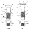
- FIG. 3 illustrates another embodiment of the fastener showing the pin and sleeve of the fastener, the pin having a longer threaded area and no frangible portion and an enlarged flush head.
- FIG. 4 illustrates another embodiment of the fastener showing the pin and sleeve of the fastener, the pin having an enlarged protruding head.
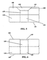
- FIG. 5 illustrates a plurality of workpieces having aligned holes for installation of the fastener to secure the workpieces together.
- FIG. 6 illustrates a plurality of workpieces having aligned holes for installation of the fastener to secure the workpieces together, the outer portion of one of the workpieces having a countersink.
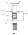
- FIG. 7 illustrates the exemplary fastener before the pin has been pushed or pulled through the sleeve.
- the sleeve has not expanded and stretched to a desired interference fit.
- FIG. 8 illustrates the fastener after the pin has been pushed or pulled into position and also illustrates the collar placed onto the pin prior to swaging.
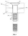
- FIG. 9 illustrates the fastener with the collar swaged onto the threaded portion of the pin to secure the fastener prior to pintail separation.
- FIG. 10 illustrates the fastener in an engaged, installed position, after pintail separation.
- a fastener for securing together a plurality of workpieces 105, 110 and adapted to be located in aligned holes 125, 130 in such workpieces is disclosed.
- the fastener 10 includes a pin member 15, a sleeve member 20 and a collar 200.
- the fastener may include a nut instead of a collar.
- the workpieces 105, 110 can be formed with a plurality of materials, the materials including composite, metallic, or composite/metallic structures, or any combination thereof.
- the workpieces 105, 110 may be constructed from titanium, aluminum, graphite composites, or any combination thereof.
- the pin member 15 includes an elongated shank portion 40 which terminates at one end 30 with an enlarged flush head 37 or protruding head 35.
- the pin shank portion 40 includes a substantially smooth cylindrical portion 45, a threaded portion 50, and a frangible portion 60.
- the smooth cylindrical shank portion extends from the head 35, 37 and is adapted to be received by the expansion sleeve 20.
- a threaded portion 50 Following the substantially smooth cylindrical portion 45 is a threaded portion 50.
- the threaded portion 50 is generally uniformly threaded throughout its length.
- a tapered transition portion 55 smoothly merges the threaded portion 50 with the smooth cylindrical shank portion 45.
- the frangible portion 60 of the pin member 15 extends from the threaded portion 50.
- the frangible portion 60 includes a cylindrical land 70 and a pull groove portion 75 having circumferential pull grooves 75.
- a breakneck groove 65 that is located adjacent to the threaded portion 50 and defines the weakest portion of the fastener 10.
- the threaded portion 50, breakneck groove 65, straight land 70 and pull groove portion 75 has a maximum diameter which is less than the diameter of the smooth cylindrical portion 45 of the shank portion, the straight land portion 70 having a diameter smaller than that of the threaded portion 50 and pull groove portion 75.
- the expansion sleeve member 20 has a generally uniform tubular portion 80 that terminates in an enlarged flanged shaped head 85 to receive the flush head 37 or protruding head 35 of the pin member 15.
- the sleeve 20 has an internal diameter that is greater than the threaded portion 50 and frangible portions 60 of the pin 15, but less than the diameter of the smooth cylindrical shank portion 45.
- the inner diameter of the sleeve member 20 includes a low friction coating on its surface 90 to facilitate movement of the pin member 15 into the sleeve 20 during installation.
- the sleeve member 20 is coated with low friction coating to eliminate the resistance between the smooth cylindrical shank portion 45 of the pin member 15 and the inner diameter surface 90 of the sleeve tubular portion 80.
- the low friction coating on the inner diameter of the sleeve allows the pin member 15 to slide through the sleeve member 20 easier due to reduced frictional loading.
- the coating on the inside diameter surface 90 enables the installation of the fastener to function when fasteners are installed with minimum, moderate, or heavy amounts of sealant on the fastener and in the installed joint.
- the pin member 15 includes an elongated shank portion 40 which terminates at one end 30 with an enlarged head 35, 37.
- This embodiment may also have a protruding head 37 as shown in the embodiment in Figure 2 .
- the pin shank portion 40 includes a substantially smooth cylindrical portion 45, a threaded portion 50, but does not include a frangible portion.
- the smooth cylindrical shank portion extends from the head 35, 37 and is adapted to be received by the expansion sleeve 20.
- Following the substantially smooth cylindrical portion 45 is a threaded portion 50.
- the threaded portion 50 is generally uniformly threaded throughout its length.
- a tapered transition portion 55 smoothly merges the threaded portion 50 with the smooth cylindrical shank portion 45.
- the workpieces 105, 110 have aligned holes 125, 130 is shown in Fig. 5 and 6 .
- the fastener assembly 10 extends through the aligned holes 125, 130 to secure the workpieces 105, 110.
- the outer surface of the workpieces 115 receive the enlarged head of the sleeve.
- the opening in the outer workpiece 105 terminates at its outer surface 115 in a countersink potion 120, or lead in radius portion, which is shaped to receive the enlarged flange 85 of the expansion sleeve member 20.
- the outer diameter of the sleeve tubular portion 80 before the pin member 15 is pushed or pulled into the sleeve member 20 is smaller than the diameter of the holes placed in the workpieces 105, 110. Accordingly, there is a space between the outer diameter of the sleeve and the inner diameter of the holes as shown in Fig. 7 .
- the outside diameter of the sleeve tubular portion 80, in its pre-expanded state, and the diameter of the bores provide a slip fit when the tubular portion of the sleeve member 20 is located within the holes.
- the sleeve expands radially to a desired interference fit with the walls of the holes 125, 130 through workpieces 105, 110 as the pin shank portion is inserted into the sleeve member 20 as depicted in FIG. 8 .
- the sleeve member 20 is shielding the surfaces of the clearance holes from the pin shank portion, and thus, eliminating delamination of the plurality of workpieces as the pin is pushed or pulled into the sleeve member 20.
- the tapered transition portion 55 is designed and optimized to minimize the installation force required for the high interference conditions resulting from the pin member 15 installation into the sleeve member 20.
- the transition portion 55 has a shallow lead-in angle that reduces the force that is needed for installation. Since less force is needed to install the fastener 10 into the interference condition, the fastener 10 allows for much longer grip lengths while diminishing sleeve stretch and premature sleeve failure.
- the transition portion 55 may be tapered and have an angle of less than or equal to 20 degrees from the pin shank as the diameter decreases radially from the smooth shank portion to the thread portion.
- the diameter of the transition portion 55 is tapered and decreases in a uniform fashion.
- the transition portion can be any shape as long as the radius of the pin shank decreases.
- the transition portion could be a gentle radius decrease shaped as a convex curve, a concave curve or an s-shaped curve, or be in configuration that would allow a reduction in the radius between the smooth shank portion and the threaded portion of the pin.
- the transition portion 55 reduces the radius of the pin shank between 0.1016 mm (0.004 inches) to about 0.127 mm (0.005 inches) over a distance of 0.254 mm (0.010 inches) to 7.366 mm (0.290 inches).
- the sleeve 20 radially expands between about 0.0762 mm (0.003 inches) and 0.3048 mm (0.012 inches) as the fastener is installed.
- the interference of the fastener 10 with the workpieces 105, 110 is about 0.0127 mm (0.0005 inches) to 0.254 mm (0.0100 inches).
- the surface of the outer diameter of the sleeve 20 and/or the inner diameter of the holes 125, 130 is rougher or coarser. By providing a rougher surface on these two areas, the coefficient of friction between the outer surface 95 of the sleeve member 20 and the inside diameter surface 135 of the holes 125, 130 is increased. Essentially the coefficient of friction and/or the force of pushing or pulling the pin 15 into the sleeve member 20 must be lower than the coefficient of friction and/or the load between the sleeve outer diameter surface 95 and the inner diameter surface 135 of the holes to provide the radial expansion of the tubular portion 80 of the sleeve 20. Without the differential coefficient of friction, the sleeve 20 may be pulled into the holes prior to installation.
- the rougher outer surface of the sleeve and/or the inner surface of the holes combined with the lubrication on the inner surface 90 of the sleeve member 20 prevents the excessive stretching of the sleeve 20 during installation.
- the coefficient of friction between the outer surface 95 of the sleeve and inner surface 135 of the holes is greater than the coefficient of friction between the inner surface of the sleeve and the smooth cylindrical shank of the pin member.
- the difference in the coefficient of friction will allow the stretching of the sleeve member 20 to be reduced to less than 1.27 mm (0.050 inches). Additionally, the characteristics of the surfaces of the sleeve 20 allow for the use of sealant in the joint and on the fastener 10.
- the optimized angled transition portion geometry 55 of the pin member 15 is designed to minimize the installation force necessary to install the fastener 10 into the interference conditions up to 0.254 mm (0.010 inches).
- the geometry designed allows the force applied when inserting the pin to be applied perpendicular to the angled transition portion 55, instead of parallel to the insertion of the pin member 15 as with traditional bull-nose transition geometry.
- a lower force is needed to insert the pin member 15.
- the fastener 10 can be installed with a larger variety of workpieces, including metallic, composite and metallic/composite structures.
- transition geometry, the tapered transition portion 55, on the pin member 15 is also important as it allows functionality with much longer grip lengths without excessive sleeve stretch and/or premature sleeve failure.
- a clamping means is utilized.
- the clamping means could be either the threaded nut member 250 depicted in Figure 3 or the collar member 200 illustrated in Figure 8 .
- Other clamping means may also be utilized to secure the workpieces together.
- a symmetrically shaped, tubular collar 200 of a pre-selected material is placed over the installed pin and sleeve assembly 12 as illustrated in FIG. 8 .
- the collar 200 has a counterbore portion 215 that is adapted to be located over the pin shank and a collar through bore, the inner diameter of the through bore 210 being selected to provide clearance to the pull grooves 75 and threaded portion 50 of the pin 15.
- the collar geometry is volume balanced.
- the wall thickness of the collar 200 is uniform and symmetrically shaped for swaging into the threaded portion 50 to provide the desired clamp load.
- another embodiment of the fastener 10 utilizes a nut member 250 to secure the workpieces together.
- the nut member 250 includes a threaded portion 255 to mate with the threaded portion 50 of the pin member.
- Both the collar member 200 or nut member 250 has a counterbore portion 215 at one end that allows the collar 200 or nut 250 to clear the sleeve component 20.
- the counterbore portion 215 has a diameter greater than the outer diameter of the sleeve 20.
- the installed fastener 10 has a reduced height and weight. This makes the fastener 10 a much more cost-effective solution than previous fasteners.
- Both the collar 200 or nut member 250 also include an enlarged flange 220 at one end.
- the flange 220 being in engagement with the outer surfaces 140 of the plurality of workpieces, is provided to have a predetermined area of engagement in order to distribute the installation and final clamp loads on the outer surfaces 140 of the workpieces 105, 110.
- the engagement area of the flange 220 is selected to be sufficient to resist localized delamination or crushing of the composite material at the outer surfaces of the workpieces 105, 110.
- the collar member of the fastener 10 is swaged to the threaded portion of the pin member 15 as shown in FIG. 9 .
- the collar 200 may be swaged into about 40 to 60% of the depth of the threads 50 while maintaining control of the collar material and achieving a consistent high, clamp load/preload.
- a consistent, high fastener 10 clamp significantly increases the dynamic joint performance and life of the aircraft structure.
- the high clamp/preload averages about 50 to 96% of the minimum tensile strength of the installed fastener. In more exemplary embodiments, the high clamp/preload averages about 78% of the minimum tensile strength. In typical fasteners, the high clamp/preload averages only about 50% of the minimum tensile strength.
- the controlled, partial fill of the threaded portion 50 of the pin member 15 allows for significant and even sealant flowout during installation.
- the mechanical performance of the fastener 10 is not reduced with this sealant flowout.
- the controlled, swaged fill by the collar 200 is also an improvement compared to prior art fasteners.
- the non-pressure side of the fastener 10 and the counterbores of the collar or nut has gaps between the components.
- the fastener 10 disclosed herein creates full contact on both sides of the threaded portion 50 of the pin 15, eliminating gaps. Accordingly, the fastener has better conductivity and provides a safer fastener for aerospace conditions, in addition to improving fuel tightness.
- the collar 200 When the collar 200 is swaged, it is swaged over the end portion of the sleeve member 20. As a result, the sleeve member 20 is compressed over the transition angle portion 55 of the pin 15. Accordingly, the sleeve 20 and pin 15 can then be removed as a single unit if necessary. This improves the efficiency and workability of the fastener 10 installed in various applications while also improving conductivity.
- FIG. 9 An exemplary implementation of the installed fastener 10 is illustrated in FIG. 9 .
- the fastener 10, with the pin having a shank of predetermined length can be selected to fasten the plurality of workpieces 105, 110 having a grip varying in total thickness from a minimum to a maximum total thickness. Since it is desirable to have the sleeve encompass the entire grip length, the sleeve is predetermined to have a length no less than the maximum total width of the plurality of workpieces 105, 110.
- the sleeve is placed onto the pin as is depicted in FIG. 1 .
- the sleeve 20 and pin 15 is then placed into the aligned holes of the workpieces 105, 110 so that a sufficient length of the frangible portion of the pin 15 extends beyond the outer surface of the plurality of workpieces 105, 110 such that the tool can grip the pull grooves 75 of the pin member 15 for pull-in capability.
- the smooth cylindrical shank portion 45 of the pin member 15 will be pulled into the sleeve member 20 causing the sleeve 20 to expand radially outward.
- the magnitude of this expansion is a function of the friction and force required between the smooth cylindrical shank pin portion 45 and the inner diameter surface 90 of the sleeve and the friction and force between the outer diameter of the sleeve 95 and the inner diameter of the holes 135 in the plurality of workpieces 105, 110.
- the collar member 200 is placed over the pin member 15 and sleeve 20 so that the flange portion 220 sits against the workpiece surface 140.
- a swaging tool is utilized to swage the collar member 200 onto the threaded portion 50 of the pin member, locking the fastener 10 into place.
- the sleeve is placed onto the pin as is depicted in FIG. 3 .
- the sleeve 20 and pin 15 is then placed into the aligned holes of the workpieces 105, 110.
- the pin 15 is pushed into the sleeve 20 so that a sufficient length of the threaded portion of the pin 15 extends beyond the outer surface of the plurality of workpieces 105, 110 such that the threaded portion of the nut 250 can mate with the threaded portion of the pin.
- the nut 250 is then installed and tightened to finalize the installation.
- a unique fastener 10 is disclosed providing an interference fit within composite, metallic, and metallic/composite structures.
- the fastener 10 provides an improved dynamic joint performance as a result of better fastener interference and higher clamp loads.
- the geometry of the various components allows for the interference conditions while eliminating delamination and potential structural failure.
- the interference eliminates gaps between the fastener 10 and the structures, providing good electrical conductivity and reducing the potential for electrical sparks, increasing the safety of the structure 10.
Abstract
Description
- 1. Field
- The present disclosure relates to an improved sleeved interference fastener as defined in the preamble of independent claim 1.
- The document
EP 0 248 122 B1 is directed to a lightning protection system for enhancing electrical contact between a fastener and graphite fibres of an inner skin layer and a support structure. For this purpose, a hole in the inner skin layer and the support is provided for receiving a conductive sleeve. The sleeve is expanded in the holes formed in the inner skin layer and the support structure for receiving a fastener. The expanding of the sleeve shall create a good uniform electrical contact between the sleeve and the graphite fibres of the skin layers and support structure. - More and more graphite composite materials are being incorporated into aircraft structures. Use of graphite composites increase strength, increase life, reduce weight, reduce fuel consumption, increase payload, among other benefits. However, as these newer materials are utilized, new challenges need to be overcome in fastening technology when compared to typical metallic structures.
- Existing aerospace fasteners cannot be safely installed in interference conditions in graphite or mixed graphite-composite metallic structures. Typically, clearance fit fasteners are utilized to avoid concerns of composite delamination and potential structural failure that make these fasteners unsafe to utilize. As a result, fasteners are installed in clearance holes that result in the reduction of dynamic joint performance, gaps in the structure, and other structural concerns.
- The resulting gap between the fastener shank portion and hole prevent uniform contact of structural components. Consequently, safe dissipation of lightning strike current/energy, and electro-magnetic currents is a major concern. Currently, aircraft manufacturers are resorting to elaborate, expensive, and sometimes risky alternative methods to properly ground the structure. For example, copper, or another low conductive strip, may be incorporated onto the surface of the workpieces to provide a preferential low resistance path for any current. Additionally, a film adhesive containing a conductive fiber carrier film capable of conducting high currents between two workpieces may be utilized. However, both of these methods are very expensive and not a cost effective way to provide safe dissipation of current.
- Additionally, prior fasteners cannot be installed with significant amounts of sealant, as is required in most aircraft structures. If sufficient sealant is utilized during installation, the coefficient of friction between the fastener assembly and the workpieces is reduced hindering installation capability. Additionally, there is an inability to flow any excess sealant out of the joint.
- Further, previous pins with mating sleeves manufactured for interference applications are only capable of being installed in 100% graphite composite materials. In addition, these fasteners are limited to applications of short lengths and small diameters. Prior fasteners cannot be installed in any composite/metallic structures and most 100% percent composite structures.
- Additionally, previous fasteners for interference applications are only available in shear load range strength capabilities. The collars utilized in these fasteners are typically commercially pure titanium and subject to creep at fairly low elevated temperatures.
- Thus, there is a need to provide a fastener that allows for interference applications without the possibility of delamination and structural failure.
- There is also a need to provide a fastener that may be used in a variety of different applications. Utilization of a fastener in a variety of composite/metallic structures is needed.
- Additionally, there is a need to provide fasteners which provide safe dissipation of electrical currents caused by lightning strikes and/or static electricity. Fasteners that allow for uniform contact of the structural components will provide the necessary dissipation and a safer, more cost effective solution to the problems involving electrical currents.
- In one aspect of the present disclosure, a sleeved interference fastener of the kind as defined in independent claim 1 is disclosed. The pin member includes an elongated smooth cylindrical shank portion and an enlarged head for mating with the sleeve. In some embodiments, there is a countersink or protruding head for engagement with a flared end of the sleeve. The pin member also includes a threaded portion and a frangible portion axially aligned with the smooth cylindrical shank portion. The frangible portion includes a pull groove portion having circumferential pull grooves adapted to be gripped for applying a relative axial force to pull the pin member into the sleeve. The pin member includes a breakneck groove between the threaded portion and the frangible portion. As the fastener is installed, the frangible portion is separated at the breakneck groove.
- The pin includes a transition portion between the smooth cylindrical shank portion and the treaded portion designed and optimized to minimize the installation force required for the high interference conditions resulting from installation. In exemplary embodiments, the transition portion may be tapered and have an angle less than or equal to 20 degrees from the pin shank. In other embodiments, the transition portion reduces the radial diameter of the pin shank between 0.1016 mm (0.004 inches) to about 0.127 mm (0.005 inches) over a distance of 0.254 mm (0.010 inches) to 7.366 mm (0.290 inches) between the smooth portion and the threaded portion.
- In other embodiments, the fastener further comprises a sleeve and a clamping means to secure together workpieces. The clamping means may comprise a collar or nut member or any other means suitable to fasten the workpieces together with the pin and sleeve. The fastener is installed through aligned holes located in two or more workpieces. In some embodiments, one of the holes through the workpieces includes a countersink, or lead in radius, on its outer opening.
- The sleeve, adapted to fit over the smooth cylindrical shank portion, includes a tubular portion and an enlarged end for engagement with the outer surface of the workpiece. In some embodiments, there is a flared end for engagement with the countersink portion in the workpieces. The sleeve has a length greater than the maximum total thickness of the workpieces to be joined at the location of the aligned holes. The tubular portion of the sleeve has an inner diameter less than the diameter of the smooth cylindrical shank portion and an outer diameter sized to permit fitting of the sleeve into the aligned clearance holes of the workpieces.
- In one aspect, the pin member has a smooth cylindrical shank portion with a diameter greater than the maximum inner diameter of the sleeve. When the smooth cylindrical shank portion enters into and pulls through the sleeve, the sleeve radially expands into an interference fit with the walls of the holes of the workpieces.
- The tubular collar member is adapted to be fit over the threaded portion of the pin member including a counterbore to enable the collar to provide clearance over the sleeve, and an annular flange portion at one end for engagement with the other outer surface of the workpieces. The collar member includes an enlarged cylindrical shank portion having a uniform outside diameter adapted to be swaged into the threaded portion of the pin.
- In another embodiment, the nut member is adapted to fit the threaded portion of the pin member including a counterbore to enable the nut member to provide clearance over the sleeve, and an annular flange portion at one end for engagement with the other outer surface of the workpieces. The nut member includes a threaded portion to be threaded onto the threaded portion of the pin to secure the fastener to the workpieces.
- In another aspect, the sleeve member includes lubrication on the inner diameter surface to reduce friction as the pin smooth cylindrical shank portion enters the sleeve. The outer diameter surface of the sleeve and/or the inner diameter of the aligned holes has a rougher surface. In particular embodiments, the coefficient of friction between the inner surface of the sleeve and the smooth cylindrical shank portion of the pin member is less than the coefficient of friction between the outer surface of the sleeve and inner diameter of the holes, allowing the sleeve to expand radially upon insertion of the smooth cylindrical shank portion of the pin member to be in an interference fit.
- In a further aspect, a fastener is disclosed that has the capability of being installed in composite, metallic, or composite/metallic structures. For example, the disclosed fastener could be installed in, for example, graphite composites, titanium, aluminum, or a mixture of these components.
- In another aspect, as a result of the fastener interference, gaps between the fastener and the structure are eliminated thereby providing good electrical conductivity between components. As a result, the potential for electrical sparks is reduced, providing a safer fastener for use with aerospace applications.
- In another aspect, the fastener has interference capability of 0.0127 mm (0.0005 inches) to 0.254 mm (0.0100 inches) in composite and/or metallic structures without risk of composite delamination or damage.
- In an additional aspect of the present disclosure, the fastener has a functional grip capability of about 1.5748 mm (0.062 inches) to about 3.556 mm (0.140 inches).
- Other objects, features, and advantages of the present disclosure will become apparent from the subsequent description and the appended claims, taken in conjunction with the accompanying drawings
- The foregoing aspects and advantages of present disclosure will become more readily apparent and understood with reference to the following detailed description, when taken in conjunction with the accompanying drawings, wherein:
-
FIG. 1 illustrates an exemplary embodiment of the fastener showing the pin and the sleeve of the fastener, the pin having an enlarged flush head. -
FIG. 2 illustrates another exemplary of the fastener showing the pin and the sleeve of the fastener, the pin having an enlarged protruding head -
FIG. 3 illustrates another embodiment of the fastener showing the pin and sleeve of the fastener, the pin having a longer threaded area and no frangible portion and an enlarged flush head. -
FIG. 4 illustrates another embodiment of the fastener showing the pin and sleeve of the fastener, the pin having an enlarged protruding head. -
FIG. 5 illustrates a plurality of workpieces having aligned holes for installation of the fastener to secure the workpieces together. -
FIG. 6 illustrates a plurality of workpieces having aligned holes for installation of the fastener to secure the workpieces together, the outer portion of one of the workpieces having a countersink. -
FIG. 7 illustrates the exemplary fastener before the pin has been pushed or pulled through the sleeve. The sleeve has not expanded and stretched to a desired interference fit. -
FIG. 8 illustrates the fastener after the pin has been pushed or pulled into position and also illustrates the collar placed onto the pin prior to swaging. -
FIG. 9 illustrates the fastener with the collar swaged onto the threaded portion of the pin to secure the fastener prior to pintail separation. -
FIG. 10 illustrates the fastener in an engaged, installed position, after pintail separation. - A fastener for securing together a plurality of
workpieces holes fastener 10 includes apin member 15, asleeve member 20 and acollar 200. In other embodiments, the fastener may include a nut instead of a collar. In exemplary embodiments, theworkpieces workpieces - An embodiment of the pin and
sleeve assembly 12 is shown inFIG. 1 and 2 . Thepin member 15 includes anelongated shank portion 40 which terminates at oneend 30 with anenlarged flush head 37 or protrudinghead 35. Thepin shank portion 40 includes a substantially smoothcylindrical portion 45, a threadedportion 50, and afrangible portion 60. The smooth cylindrical shank portion extends from thehead expansion sleeve 20. Following the substantially smoothcylindrical portion 45 is a threadedportion 50. The threadedportion 50 is generally uniformly threaded throughout its length. A taperedtransition portion 55 smoothly merges the threadedportion 50 with the smoothcylindrical shank portion 45. - The
frangible portion 60 of thepin member 15 extends from the threadedportion 50. Thefrangible portion 60 includes acylindrical land 70 and apull groove portion 75 having circumferential pullgrooves 75. Abreakneck groove 65 that is located adjacent to the threadedportion 50 and defines the weakest portion of thefastener 10. - In some embodiments, the threaded
portion 50,breakneck groove 65,straight land 70 and pullgroove portion 75 has a maximum diameter which is less than the diameter of the smoothcylindrical portion 45 of the shank portion, thestraight land portion 70 having a diameter smaller than that of the threadedportion 50 and pullgroove portion 75. - In this embodiment, the
expansion sleeve member 20 has a generally uniformtubular portion 80 that terminates in an enlarged flanged shapedhead 85 to receive theflush head 37 or protrudinghead 35 of thepin member 15. Thesleeve 20 has an internal diameter that is greater than the threadedportion 50 andfrangible portions 60 of thepin 15, but less than the diameter of the smoothcylindrical shank portion 45. - The inner diameter of the
sleeve member 20 includes a low friction coating on itssurface 90 to facilitate movement of thepin member 15 into thesleeve 20 during installation. In a particular embodiment, thesleeve member 20 is coated with low friction coating to eliminate the resistance between the smoothcylindrical shank portion 45 of thepin member 15 and theinner diameter surface 90 of thesleeve tubular portion 80. The low friction coating on the inner diameter of the sleeve allows thepin member 15 to slide through thesleeve member 20 easier due to reduced frictional loading. - Additionally, the coating on the
inside diameter surface 90 enables the installation of the fastener to function when fasteners are installed with minimum, moderate, or heavy amounts of sealant on the fastener and in the installed joint. - Another embodiment of the fastener is illustrated in
Fig. 3 and Fig. 4 . In this embodiment, thepin member 15 includes anelongated shank portion 40 which terminates at oneend 30 with anenlarged head head 37 as shown in the embodiment inFigure 2 . Thepin shank portion 40 includes a substantially smoothcylindrical portion 45, a threadedportion 50, but does not include a frangible portion. The smooth cylindrical shank portion extends from thehead expansion sleeve 20. Following the substantially smoothcylindrical portion 45 is a threadedportion 50. The threadedportion 50 is generally uniformly threaded throughout its length. A taperedtransition portion 55 smoothly merges the threadedportion 50 with the smoothcylindrical shank portion 45. - The
workpieces holes Fig. 5 and 6 . Thefastener assembly 10 extends through the alignedholes workpieces workpieces 115 receive the enlarged head of the sleeve. As seen in the embodiment depicted inFigure 6 , the opening in theouter workpiece 105 terminates at itsouter surface 115 in acountersink potion 120, or lead in radius portion, which is shaped to receive theenlarged flange 85 of theexpansion sleeve member 20. - The outer diameter of the
sleeve tubular portion 80 before thepin member 15 is pushed or pulled into thesleeve member 20 is smaller than the diameter of the holes placed in theworkpieces Fig. 7 . The outside diameter of thesleeve tubular portion 80, in its pre-expanded state, and the diameter of the bores provide a slip fit when the tubular portion of thesleeve member 20 is located within the holes. - During installation, as the
pin member 15 is pushed or pulled through the sleeve, the sleeve expands radially to a desired interference fit with the walls of theholes workpieces sleeve member 20 as depicted inFIG. 8 . In this manner, thesleeve member 20 is shielding the surfaces of the clearance holes from the pin shank portion, and thus, eliminating delamination of the plurality of workpieces as the pin is pushed or pulled into thesleeve member 20. - The tapered
transition portion 55 is designed and optimized to minimize the installation force required for the high interference conditions resulting from thepin member 15 installation into thesleeve member 20. Thetransition portion 55 has a shallow lead-in angle that reduces the force that is needed for installation. Since less force is needed to install thefastener 10 into the interference condition, thefastener 10 allows for much longer grip lengths while diminishing sleeve stretch and premature sleeve failure. - In exemplary embodiments, the
transition portion 55 may be tapered and have an angle of less than or equal to 20 degrees from the pin shank as the diameter decreases radially from the smooth shank portion to the thread portion. In the embodiment illustrated, the diameter of thetransition portion 55 is tapered and decreases in a uniform fashion. However, the transition portion can be any shape as long as the radius of the pin shank decreases. For example, the transition portion could be a gentle radius decrease shaped as a convex curve, a concave curve or an s-shaped curve, or be in configuration that would allow a reduction in the radius between the smooth shank portion and the threaded portion of the pin. In these embodiments, thetransition portion 55 reduces the radius of the pin shank between 0.1016 mm (0.004 inches) to about 0.127 mm (0.005 inches) over a distance of 0.254 mm (0.010 inches) to 7.366 mm (0.290 inches). In exemplary embodiments, thesleeve 20 radially expands between about 0.0762 mm (0.003 inches) and 0.3048 mm (0.012 inches) as the fastener is installed. In an exemplary embodiment, the interference of thefastener 10 with theworkpieces - As a result of the fastener interference of the disclosed
fastener 10, gaps between thefastener 10 and the workpiece structures are eliminated. Accordingly, good electrical conductivity between the components is provided. The potential for electrical sparks is reduced making thefastener 10 more safe for use in aerospace applications. - In exemplary embodiments, the surface of the outer diameter of the
sleeve 20 and/or the inner diameter of theholes outer surface 95 of thesleeve member 20 and theinside diameter surface 135 of theholes pin 15 into thesleeve member 20 must be lower than the coefficient of friction and/or the load between the sleeveouter diameter surface 95 and theinner diameter surface 135 of the holes to provide the radial expansion of thetubular portion 80 of thesleeve 20. Without the differential coefficient of friction, thesleeve 20 may be pulled into the holes prior to installation. - In exemplary embodiments, the rougher outer surface of the sleeve and/or the inner surface of the holes combined with the lubrication on the
inner surface 90 of thesleeve member 20 prevents the excessive stretching of thesleeve 20 during installation. The coefficient of friction between theouter surface 95 of the sleeve andinner surface 135 of the holes is greater than the coefficient of friction between the inner surface of the sleeve and the smooth cylindrical shank of the pin member. As a result, thesleeve 20 expands radially into the interference position and the stretching of thesleeve 20 is diminished. - In exemplary applications, the difference in the coefficient of friction will allow the stretching of the
sleeve member 20 to be reduced to less than 1.27 mm (0.050 inches). Additionally, the characteristics of the surfaces of thesleeve 20 allow for the use of sealant in the joint and on thefastener 10. - In exemplary embodiments, the optimized angled
transition portion geometry 55 of thepin member 15 is designed to minimize the installation force necessary to install thefastener 10 into the interference conditions up to 0.254 mm (0.010 inches). The geometry designed allows the force applied when inserting the pin to be applied perpendicular to theangled transition portion 55, instead of parallel to the insertion of thepin member 15 as with traditional bull-nose transition geometry. A lower force is needed to insert thepin member 15. As a result of the lower force required, thefastener 10 can be installed with a larger variety of workpieces, including metallic, composite and metallic/composite structures. - The transition geometry, the tapered
transition portion 55, on thepin member 15 is also important as it allows functionality with much longer grip lengths without excessive sleeve stretch and/or premature sleeve failure. - To fully clamp the workpieces together, a clamping means is utilized. The clamping means could be either the threaded
nut member 250 depicted inFigure 3 or thecollar member 200 illustrated inFigure 8 . Other clamping means may also be utilized to secure the workpieces together. - In one embodiment, a symmetrically shaped,
tubular collar 200 of a pre-selected material is placed over the installed pin andsleeve assembly 12 as illustrated inFIG. 8 . As theworkpieces pin member 15. Thecollar 200 has acounterbore portion 215 that is adapted to be located over the pin shank and a collar through bore, the inner diameter of the throughbore 210 being selected to provide clearance to thepull grooves 75 and threadedportion 50 of thepin 15. The collar geometry is volume balanced. Significantly, the wall thickness of thecollar 200 is uniform and symmetrically shaped for swaging into the threadedportion 50 to provide the desired clamp load. - As illustrated in
FIG. 3 , another embodiment of thefastener 10 utilizes anut member 250 to secure the workpieces together. Thenut member 250 includes a threadedportion 255 to mate with the threadedportion 50 of the pin member. - Both the
collar member 200 ornut member 250 has acounterbore portion 215 at one end that allows thecollar 200 ornut 250 to clear thesleeve component 20. Thus, thecounterbore portion 215 has a diameter greater than the outer diameter of thesleeve 20. As a result, the installedfastener 10 has a reduced height and weight. This makes the fastener 10 a much more cost-effective solution than previous fasteners. - Both the
collar 200 ornut member 250 also include anenlarged flange 220 at one end. Theflange 220, being in engagement with theouter surfaces 140 of the plurality of workpieces, is provided to have a predetermined area of engagement in order to distribute the installation and final clamp loads on theouter surfaces 140 of theworkpieces workpieces flange 220 is selected to be sufficient to resist localized delamination or crushing of the composite material at the outer surfaces of theworkpieces - The collar member of the
fastener 10 is swaged to the threaded portion of thepin member 15 as shown inFIG. 9 . In particular embodiments, the optimized collar geometry balanced with the existing thread forms and installation tools to allow swaging of the collar into the threadedportion 50. Thecollar 200 may be swaged into about 40 to 60% of the depth of thethreads 50 while maintaining control of the collar material and achieving a consistent high, clamp load/preload. - A consistent,
high fastener 10 clamp significantly increases the dynamic joint performance and life of the aircraft structure. In particular embodiments, the high clamp/preload averages about 50 to 96% of the minimum tensile strength of the installed fastener. In more exemplary embodiments, the high clamp/preload averages about 78% of the minimum tensile strength. In typical fasteners, the high clamp/preload averages only about 50% of the minimum tensile strength. - Additionally, the controlled, partial fill of the threaded
portion 50 of thepin member 15 allows for significant and even sealant flowout during installation. The mechanical performance of thefastener 10 is not reduced with this sealant flowout. - The controlled, swaged fill by the
collar 200 is also an improvement compared to prior art fasteners. In typical applications, there is an inherent gap between the internal and external threads of the pin member and the collar or nut. In addition, the non-pressure side of thefastener 10 and the counterbores of the collar or nut has gaps between the components. Thefastener 10 disclosed herein creates full contact on both sides of the threadedportion 50 of thepin 15, eliminating gaps. Accordingly, the fastener has better conductivity and provides a safer fastener for aerospace conditions, in addition to improving fuel tightness. - When the
collar 200 is swaged, it is swaged over the end portion of thesleeve member 20. As a result, thesleeve member 20 is compressed over thetransition angle portion 55 of thepin 15. Accordingly, thesleeve 20 andpin 15 can then be removed as a single unit if necessary. This improves the efficiency and workability of thefastener 10 installed in various applications while also improving conductivity. - An exemplary implementation of the installed
fastener 10 is illustrated inFIG. 9 . Thefastener 10, with the pin having a shank of predetermined length can be selected to fasten the plurality ofworkpieces workpieces - For particular applications of the disclosed fastener, 110% of minimum mechanical performance is achieved with a functional grip capability of about 3.4544 mm (0.136 inches). Typical fasteners only have a functional grip capability of about 1.5748 mm (0.062 inches). Having a longer functional grip capability variance provides the
fastener 10 with more versatility to be used with different applications. - To install the
fastener 10, the sleeve is placed onto the pin as is depicted inFIG. 1 . Thesleeve 20 andpin 15 is then placed into the aligned holes of theworkpieces pin 15 extends beyond the outer surface of the plurality ofworkpieces pull grooves 75 of thepin member 15 for pull-in capability. - As the
pin member 15 is pulled by the tool, the smoothcylindrical shank portion 45 of thepin member 15 will be pulled into thesleeve member 20 causing thesleeve 20 to expand radially outward. The magnitude of this expansion is a function of the friction and force required between the smooth cylindricalshank pin portion 45 and theinner diameter surface 90 of the sleeve and the friction and force between the outer diameter of thesleeve 95 and the inner diameter of theholes 135 in the plurality ofworkpieces - Then the
collar member 200 is placed over thepin member 15 andsleeve 20 so that theflange portion 220 sits against theworkpiece surface 140. At this point, a swaging tool is utilized to swage thecollar member 200 onto the threadedportion 50 of the pin member, locking thefastener 10 into place. - In another embodiment, to install the
fastener 10, the sleeve is placed onto the pin as is depicted inFIG. 3 . Thesleeve 20 andpin 15 is then placed into the aligned holes of theworkpieces pin 15 is pushed into thesleeve 20 so that a sufficient length of the threaded portion of thepin 15 extends beyond the outer surface of the plurality ofworkpieces nut 250 can mate with the threaded portion of the pin. Thenut 250 is then installed and tightened to finalize the installation. - Thus, a
unique fastener 10 is disclosed providing an interference fit within composite, metallic, and metallic/composite structures. Thefastener 10 provides an improved dynamic joint performance as a result of better fastener interference and higher clamp loads. The geometry of the various components allows for the interference conditions while eliminating delamination and potential structural failure. The interference eliminates gaps between thefastener 10 and the structures, providing good electrical conductivity and reducing the potential for electrical sparks, increasing the safety of thestructure 10. - While the above description contains many particulars, these should not be considered limitations on the scope of the disclosure, but rather a demonstration of embodiments thereof. The fastener and uses disclosed herein include any combination of the different species or embodiments disclosed. Accordingly, it is not intended that the scope of the disclosure in any way be limited by the above description. The various elements of the claims and claims themselves may be combined any combination, in accordance with the teachings of the present disclosure, which includes the claims.
Claims (8)
- A sleeved interference fastener (10) adapted to be installed in aligned holes (125, 130) through two or more workpieces (105, 110), the sleeve interference fastener (10) comprising:- a sleeve member (20) having an enlarged head (85) at one end and a tubular portion (80), the tubular portion (80) having an inner diameter (90) and an outer diameter (95), wherein the outer diameter (95) of the tubular portion (80) is foreseen to be less than an inner diameter of the aligned holes (125, 130) of the structure (105, 110); and- a pin member (15) having an enlarged pin head (35, 37) at one end, a threaded portion (50) at an opposite end, and a smooth cylindrical shank portion (45) therein between, wherein the smooth shank portion (45) is located below the enlarged pin head (35, 37) and has a diameter greater than the inner diameter of the tubular portion (80) of the sleeve member (20),wherein the sleeve member (20) is adapted to expand radially over the smooth cylindrical shank portion (45) to form an interference fit between the outer diameter of the sleeve member (20) and the aligned holes (125, 130) through the two or more workpieces (105, 110) so as to provide an installed position of the sleeve interference fastener (10),
characterized in that
the fastener (10) further comprises a transition portion (55) between the smooth cylindrical shank portion (45) and the treaded portion (50), the transition portion (55) having a configuration that allows a reduction in the radius between the smooth cylindrical shank portion (45) and the threaded portion (50) of the pin member (15) for minimizing the installation force required for installing the pin member (15) into the sleeve member (20), wherein the coefficient of friction between the inner surface of the sleeve member (20) and the smooth cylindrical shank portion (45) of the pin member (15) is so chosen as to be less than the coefficient of friction between the outer surface of the sleeve member (20) and the inside diameter surface (135) of the aligned holes (125, 130) through the two or more workpieces (105, 110) in order to reduce the amount of stretch of the sleeve member (20) thereby allowing the smooth cylindrical shank portion (45) to expand the sleeve member (20) into an interference fit with the two or more workpieces (105, 110). - The fastener (10) of claim 1, wherein the transition portion (55) is a tapered transition portion having an angle less than or equal to 20 degrees from the smooth cylindrical shank portion (45) as the diameter decreases radially from the smooth shank portion (45) to the threaded portion (50).
- The fastener (10) of claim 1, wherein the transition portion (55) is a transition portion having a length of between 0.254 mm (0.010 inches) and 0.737 mm (0.0290 inches), the diameter of the transition portion decreasing radially between 0.102 mm (0.004 inches) and 0.127 mm (0.005 inches) as it extends from the smooth cylindrical shank portion (45) to the threaded portion (50).
- The fastener (10) of one of the claims 1 to 3, wherein the fastener (10) further comprises clamping means (200, 250) adapted to fit over the threaded portion (50) of the pin member (15).
- The fastener (10) of claim 4, wherein the clamping means (200, 250) is a threaded nut member (250).
- The fastener (10) of claim 4, wherein the clamping means (200, 250) is a collar member (200).
- The fastener (10) of claim 5 or 6, wherein the clamping means (200, 250) comprises a counterbore portion (215), wherein the counterbore portion (215) has a diameter greater than the outer diameter of the sleeve member (20).
- The fastener (10) of one of the claims 1 to 7, wherein the transition portion (55) is configured such as to radially expand the sleeve member (20) by about 0.0127 mm (0.0005 inches) to about 0.254 mm (0.0100 inches) as the pin member (15) is installed in the sleeve member (20).
Priority Applications (1)
| Application Number | Priority Date | Filing Date | Title |
|---|---|---|---|
| DE202007019163U DE202007019163U1 (en) | 2006-09-21 | 2007-09-19 | High performance press-fit fastener for composite applications |
Applications Claiming Priority (1)
| Application Number | Priority Date | Filing Date | Title |
|---|---|---|---|
| US11/533,964 US7695226B2 (en) | 2006-09-21 | 2006-09-21 | High performance sleeved interference fasteners for composite applications |
Publications (4)
| Publication Number | Publication Date |
|---|---|
| EP1903221A2 EP1903221A2 (en) | 2008-03-26 |
| EP1903221A3 EP1903221A3 (en) | 2008-08-27 |
| EP1903221B1 true EP1903221B1 (en) | 2011-03-30 |
| EP1903221B2 EP1903221B2 (en) | 2015-06-17 |
Family
ID=38787470
Family Applications (1)
| Application Number | Title | Priority Date | Filing Date |
|---|---|---|---|
| EP07116776.1A Active EP1903221B2 (en) | 2006-09-21 | 2007-09-19 | Sleeved interference fasteners for composite materials |
Country Status (13)
| Country | Link |
|---|---|
| US (4) | US7695226B2 (en) |
| EP (1) | EP1903221B2 (en) |
| JP (2) | JP5044344B2 (en) |
| KR (1) | KR100915180B1 (en) |
| CN (1) | CN101153623B (en) |
| AT (1) | ATE503935T1 (en) |
| AU (1) | AU2007216793B2 (en) |
| BR (1) | BRPI0703097B1 (en) |
| CA (1) | CA2603635C (en) |
| DE (3) | DE602007013505D1 (en) |
| ES (1) | ES2361197T5 (en) |
| MX (1) | MX2007011651A (en) |
| WO (1) | WO2008036666A2 (en) |
Cited By (2)
| Publication number | Priority date | Publication date | Assignee | Title |
|---|---|---|---|---|
| JP2013104426A (en) * | 2011-11-16 | 2013-05-30 | United Technologies Corp <Utc> | Gas turbine engine and flexible seal system for the same |
| CN103492729A (en) * | 2011-04-28 | 2014-01-01 | 三菱重工业株式会社 | Method for fastening composite material component |
Families Citing this family (114)
| Publication number | Priority date | Publication date | Assignee | Title |
|---|---|---|---|---|
| US7375277B1 (en) | 2000-06-26 | 2008-05-20 | Fatigue Technology, Inc. | Double flanged bushings and installation methods |
| US7448652B2 (en) | 2003-07-31 | 2008-11-11 | Fatigue Technology Inc. | Tubular metal fitting expandable in a wall opening and method of installation |
| US20070110541A1 (en) * | 2005-10-28 | 2007-05-17 | Fatigue Technology, Inc. | Radially displaceable bushing for retaining a member relative to a structural workpiece |
| DE102005052014B4 (en) * | 2005-11-02 | 2008-03-20 | Airbus Deutschland Gmbh | Tapered bolt connection and use of a tapered bolt connection |
| EP3199292B1 (en) | 2005-12-28 | 2020-03-11 | Fatigue Technology, Inc. | Mandrel assembly and method of using the same |
| CA2637100A1 (en) * | 2006-01-11 | 2007-07-19 | Fatigue Technology, Inc. | Bushing kits, bearings, and methods of installation |
| JP5258751B2 (en) | 2006-04-27 | 2013-08-07 | ファティーグ テクノロジー インコーポレイテッド | Alignment device and method of using the same |
| JP5204096B2 (en) * | 2006-04-27 | 2013-06-05 | ファティーグ テクノロジー インコーポレイテッド | Wave relaxation geometry in a structural member that is radially expandable into the workpiece |
| US7958766B2 (en) | 2006-06-29 | 2011-06-14 | Fatigue Technology, Inc. | Self-aligning tools and a mandrel with retention sleeve |
| EP2489462A1 (en) | 2006-08-28 | 2012-08-22 | Fatigue Technology, Inc. | System for processing a workpiece and method of expanding an expandable member |
| US7898785B2 (en) * | 2006-12-07 | 2011-03-01 | The Boeing Company | Lightning protection system for an aircraft composite structure |
| US7966711B2 (en) | 2007-08-14 | 2011-06-28 | The Boeing Company | Method and apparatus for fastening components using a composite two-piece fastening system |
| EP2210001B1 (en) * | 2007-10-16 | 2017-08-02 | Fatigue Technology, Inc. | Expandable fastener assembly with deformed collar |
| US8393068B2 (en) * | 2007-11-06 | 2013-03-12 | The Boeing Company | Method and apparatus for assembling composite structures |
| JP5606332B2 (en) * | 2008-03-07 | 2014-10-15 | ファティーグ テクノロジー インコーポレイテッド | Expandable member with wave suppression and method of use |
| EP2318726B1 (en) | 2008-07-18 | 2015-09-02 | Fatigue Technology, Inc. | Nut plate assembly and methods of using the same |
| US8382413B2 (en) * | 2008-11-17 | 2013-02-26 | The Boeing Company | Conductive sleeved fastener assembly |
| US9562556B2 (en) | 2009-04-03 | 2017-02-07 | Arconic Inc. | Fasteners with conforming sleeves |
| WO2010115084A1 (en) * | 2009-04-03 | 2010-10-07 | Alcoa Inc. | Fasteners with conforming sleeves |
| EP2417369B1 (en) * | 2009-04-10 | 2014-04-02 | Fatigue Technology, Inc. | Installable assembly having an expandable outer member and a fastener with a mandrel |
| US8262331B2 (en) * | 2009-05-04 | 2012-09-11 | Polaris Fastening Consulting, Llc | Integrated expanding sleeve hole filling threaded fastener |
| FR2948637B1 (en) * | 2009-07-31 | 2012-01-20 | Airbus Operations Sas | AIRCRAFT COMPRISING ELECTRICAL EQUIPMENT AND PARTS OF COMPOSITE MATERIAL |
| US8434984B2 (en) * | 2009-09-09 | 2013-05-07 | Polaris Fastening Consulting, Llc | Self-interlocking sleeve-core shear pin fastener |
| WO2011050040A1 (en) | 2009-10-22 | 2011-04-28 | Alcoa Inc. | Enhanced conductivity sleeved fastener and method for making same |
| WO2011084624A2 (en) * | 2009-12-16 | 2011-07-14 | Fatigue Technology, Inc. | Modular nut plate assemblies and methods of using the same |
| US8529177B2 (en) * | 2010-02-15 | 2013-09-10 | Polaris Fastening Consulting, Llc | Integrated pin/sleeve blind fastener |
| GB2481021B (en) * | 2010-06-08 | 2014-02-26 | Joseph Emmanuel Brown | Quick fixine |
| US8317789B2 (en) | 2010-10-11 | 2012-11-27 | Kettering University | Compression transmission collar for fastening |
| CN102478286B (en) * | 2010-11-26 | 2016-03-02 | 乐金电子(天津)电器有限公司 | The footing component of the compressor leg of fixing Split type air conditioner outdoor machine |
| US8791375B2 (en) * | 2010-12-16 | 2014-07-29 | The Boeing Company | Electrically conductive bushing connection to structure for current path |
| ES2634422T3 (en) * | 2011-03-24 | 2017-09-27 | Alcoa Inc. | Hybrid collar for fastening systems |
| WO2012167136A2 (en) | 2011-06-03 | 2012-12-06 | Fatigue Technology, Inc. | Expandable crack inhibitors and methods of using the same |
| US9114449B2 (en) | 2011-06-15 | 2015-08-25 | Fatigue Technology, Inc. | Modular nut plates with closed nut assemblies |
| US20130075150A1 (en) * | 2011-09-27 | 2013-03-28 | Christopher L. Newbolt | Bushing for use in providing electromagnetic effects protection |
| US8266941B1 (en) | 2011-12-09 | 2012-09-18 | Alcoa Inc. | Fastener installation tool |
| US10130985B2 (en) | 2012-01-30 | 2018-11-20 | Fatigue Technology, Inc. | Smart installation/processing systems, components, and methods of operating the same |
| DE102012202053A1 (en) | 2012-02-10 | 2013-08-14 | Airbus Operations Gmbh | Connection arrangement and method |
| US9802715B2 (en) | 2012-03-29 | 2017-10-31 | The Boeing Company | Fastener systems that provide EME protection |
| US9611052B2 (en) | 2012-03-29 | 2017-04-04 | The Boeing Company | Fastener systems that provide EME protection |
| CN102661308A (en) * | 2012-05-23 | 2012-09-12 | 无锡商业职业技术学院 | Anti-loosening fastening screw |
| US8794890B2 (en) * | 2012-08-20 | 2014-08-05 | Alcoa Inc. | Variable wall thickness collar |
| DE102012019849B4 (en) * | 2012-10-10 | 2023-11-02 | Böllhoff Verbindungstechnik GmbH | Component with sealing plug and method for forming a component insert |
| FR2998015B1 (en) | 2012-11-12 | 2015-05-29 | Lisi Aerospace | DEVICE FOR SECURING FASTENING |
| EP2920472B1 (en) * | 2012-11-14 | 2017-08-02 | UMS Skeldar Sweden AB | Fastening means and attachment assembly |
| CN102943803B (en) * | 2012-11-22 | 2015-04-22 | 无锡安士达五金有限公司 | Rivet type bolt |
| US9404521B2 (en) | 2012-12-12 | 2016-08-02 | Polaris Fastening Consulting, Llc | Self integrating structural insert sleeve |
| CN103062182B (en) * | 2013-01-04 | 2015-07-08 | 浙江西子富沃德电机有限公司 | Integrated bolt with limiting and guiding functions |
| US9343824B2 (en) * | 2013-02-04 | 2016-05-17 | The Boeing Company | Sleeved fastener assembly |
| US9331402B2 (en) * | 2013-02-04 | 2016-05-03 | The Boeing Company | Conductive sleeved fastener assembly |
| US9169862B2 (en) | 2013-02-19 | 2015-10-27 | The Boeing Company | Self-aligning sleeved protruding head fasteners with electromagnetic effect protection features |
| CN103267054A (en) * | 2013-04-20 | 2013-08-28 | 湖北博士隆科技有限公司 | Highly-locking fastening method |
| CN103233963B (en) * | 2013-05-19 | 2015-10-28 | 眉山南车紧固件科技有限公司 | The two-sided two component connecting means without bump and two countersunk head pulling rivet |
| US9291187B2 (en) | 2013-05-20 | 2016-03-22 | The Boeing Company | Nut, washer and fastener head for electromagnetic effect protection |
| FR3008754B1 (en) * | 2013-07-19 | 2015-09-04 | Lisi Aerospace | METAL FASTENING |
| US9194412B2 (en) * | 2013-09-19 | 2015-11-24 | Alcoa Inc. | Lock bolt collar with high standoff internal bead |
| CA2908220C (en) * | 2013-09-19 | 2017-06-27 | Alcoa Inc. | Rivet |
| RU2592958C2 (en) * | 2013-11-06 | 2016-07-27 | Зе Боинг Компани | Fastening systems, ensuring protection against electromagnetic effects |
| US9908637B2 (en) * | 2014-05-23 | 2018-03-06 | The Boeing Company | Modified shank fasteners for electromagnetic effect (EME) technology |
| US9759246B2 (en) | 2014-08-25 | 2017-09-12 | Arconic Inc. | Textured sleeves for fasteners |
| US9939004B2 (en) * | 2014-09-17 | 2018-04-10 | Arconic Inc | Coated fasteners with conforming seals |
| EP3194798B1 (en) | 2014-09-17 | 2020-07-15 | Howmet Aerospace Inc. | Fasteners with coated and textured pin members |
| US9702396B2 (en) | 2014-09-17 | 2017-07-11 | Arconic Inc. | Fasteners with dual skin depth washers |
| FR3026446B1 (en) | 2014-09-30 | 2017-12-01 | Lisi Aerospace | LUBRICATED INTERFERENCE FASTENING |
| GB201505247D0 (en) * | 2015-03-27 | 2015-05-13 | Short Brothers Plc | Dual load path fastener system |
| EP3104025A1 (en) * | 2015-06-11 | 2016-12-14 | HILTI Aktiengesellschaft | Expansion dowel having double coating |
| DE102015111005A1 (en) * | 2015-07-08 | 2017-01-12 | Airbus Operations Gmbh | Method for connecting two components by means of a bolt-shaped element |
| CN105065400A (en) * | 2015-08-13 | 2015-11-18 | 中国航空工业集团公司西安飞机设计研究所 | Embedding lining and method for processing out-of-tolerance holes through embedding lining |
| US10220435B2 (en) | 2015-08-26 | 2019-03-05 | Polaris Fastener Testing And Tooling, Llc | Installation tooling system for buckle and swage type fastener |
| CA2978485C (en) | 2015-08-27 | 2019-03-26 | Arconic Inc. | Fastener locking members |
| US10400808B2 (en) * | 2016-03-10 | 2019-09-03 | The Boeing Company | One-sided fastener assembly and methods and systems for installing the same |
| US10167885B2 (en) | 2016-03-21 | 2019-01-01 | United Technologies Corporation | Mechanical joint with a flanged retainer |
| CN105650081A (en) * | 2016-04-08 | 2016-06-08 | 航天精工股份有限公司 | Double-metal rivet with lining structure |
| CN106122226A (en) * | 2016-08-23 | 2016-11-16 | 无锡市东赫金属制品有限公司 | A kind of bolt of scalable screw head size |
| USD814280S1 (en) * | 2016-09-27 | 2018-04-03 | General Electric Company | Fastener |
| US10495130B2 (en) | 2016-11-11 | 2019-12-03 | The Boeing Company | Fasteners having enhanced electrical energy dispersion properties |
| JP6852176B2 (en) | 2016-12-13 | 2021-03-31 | アーコニック インコーポレイテッドArconic Inc. | Reduced electromagnetic signature of conformal conical seal fastener system |
| US10641307B2 (en) | 2017-02-20 | 2020-05-05 | The Boeing Company | Radiused lead-in for interference fit fasteners |
| US10711814B2 (en) * | 2017-02-20 | 2020-07-14 | The Boeing Company | Tapered lead-in for interference fit fasteners |
| US20180274578A1 (en) * | 2017-03-23 | 2018-09-27 | GM Global Technology Operations LLC | Joining system and method |
| EP3399197A1 (en) * | 2017-05-04 | 2018-11-07 | Fairchild Fasteners Europe - VSD GmbH | Fastener for attaching together workpieces having aligned holes therethrough |
| CN109253144A (en) * | 2017-07-12 | 2019-01-22 | 德国诺玛公司 | Comprising having the configuration fixture of the screw of reducing diameter part |
| NO344799B1 (en) * | 2017-11-01 | 2020-05-04 | Bondura Tech As | Bolt assembly for axial and radial clamping of elements joined together by means of screws |
| CN108081927A (en) * | 2017-12-13 | 2018-05-29 | 重庆飞特车辆技术有限公司 | Automobile and its car door |
| EP3749867B1 (en) * | 2018-02-07 | 2023-05-17 | Lisi Aerospace | Fastener with lubricating ring for interference fitting, and assembly method using such a fastener |
| JP6770987B2 (en) * | 2018-03-12 | 2020-10-21 | 株式会社Subaru | Composite structure, aircraft and lightning current induction method |
| US10626908B2 (en) * | 2018-03-30 | 2020-04-21 | The Boeing Company | Electromagnetic effect protective fastener with frangible collar |
| US10954991B2 (en) | 2018-03-30 | 2021-03-23 | The Boeing Company | Electromagnetic effect protective fastener with swageable termination body |
| US20210025434A1 (en) * | 2018-05-21 | 2021-01-28 | Howmet Aerospace Inc. | Fastener including a transition zone and method of use thereof |
| US10774863B2 (en) * | 2018-06-18 | 2020-09-15 | The Boeing Company | Blind fastener system with electromagnetic effects-protective coating |
| US11300147B2 (en) | 2018-07-03 | 2022-04-12 | Roller Bearing Company Of America, Inc. | Sleeves for interference fasteners |
| FR3085448B1 (en) * | 2018-09-04 | 2020-11-27 | Lisi Aerospace | SCREW WITH BREAKTHROUGH, FIXING INCLUDING SUCH SCREW, ASSEMBLY AND ASSOCIATED INSTALLATION PROCEDURE |
| CN109850124A (en) * | 2018-12-12 | 2019-06-07 | 惠阳航空螺旋桨有限责任公司 | A kind of propeller composite material radome fairing clamp device |
| US11137014B2 (en) | 2019-01-08 | 2021-10-05 | The Boeing Company | Conductive fastening system and method for improved EME performance |
| US20200291979A1 (en) * | 2019-03-15 | 2020-09-17 | Roller Bearing Company Of America, Inc. | Bolt interface coating and thread transition geometry for sleeved fasteners used in composite applications |
| US11396900B2 (en) * | 2019-05-10 | 2022-07-26 | The Boeing Company | Fastener and methods of manufacturing and use |
| USD913782S1 (en) * | 2019-06-07 | 2021-03-23 | Sps Technologies, Llc | Blind fastener sleeve |
| CN110230630A (en) * | 2019-06-20 | 2019-09-13 | 贵州航天精工制造有限公司 | A kind of connection structure and connection method for composite material or composite material and metal |
| US11313398B2 (en) * | 2019-08-19 | 2022-04-26 | The Boeing Company | Blind tack fastener and methods of manufacture |
| USD935877S1 (en) * | 2019-08-27 | 2021-11-16 | Sps Technologies, Llc | Blind fastener nut |
| USD920774S1 (en) * | 2019-08-27 | 2021-06-01 | Sps Technologies, Llc | Blind fastener |
| CN112555255B (en) * | 2019-09-26 | 2022-11-29 | 株洲中车机电科技有限公司 | Single-face fastening bolt |
| CN113898654B (en) * | 2020-03-26 | 2023-02-03 | 重庆金海标准件有限公司 | Use method of bolt with changeable threaded area |
| CN111379776A (en) * | 2020-04-14 | 2020-07-07 | 眉山中车紧固件科技有限公司 | Acorn ring groove single-side fastener and mounting method thereof |
| CN112378305B (en) * | 2020-11-02 | 2022-05-24 | 杭州汽轮机股份有限公司 | Cylindrical pin assembling method based on interference magnitude control |
| DE102020129387A1 (en) | 2020-11-09 | 2022-05-12 | Bayerische Motoren Werke Aktiengesellschaft | Screw connection system and method for producing a screw connection using a screw connection system |
| US20220154755A1 (en) * | 2020-11-13 | 2022-05-19 | Owens Corning Intellectual Capital, Llc | Acoustically attenuating fasteners |
| US20220205471A1 (en) * | 2020-12-29 | 2022-06-30 | Dana Automotive Systems Group, Llc | Locking feature for a fastener |
| TWI750992B (en) * | 2021-01-11 | 2021-12-21 | 鋐昇實業股份有限公司 | Expansion screw based fastening device |
| CN216241731U (en) * | 2021-07-29 | 2022-04-08 | 浙江印天健康科技有限公司 | Fastening screw and lifting table using same |
| FR3127425A1 (en) * | 2021-09-24 | 2023-03-31 | Safran | ASSEMBLY FOR AN AIRCRAFT TURBOMACHINE |
| CN114135557A (en) * | 2021-12-17 | 2022-03-04 | 江西洪都航空工业集团有限责任公司 | Penetrating type detachable double-faced countersunk head connecting mechanism |
| CN114713653A (en) * | 2022-03-24 | 2022-07-08 | 上海工程技术大学 | Machining method and forming die assembly for long rod part with threaded teeth for vehicle |
| CN115163630A (en) * | 2022-07-01 | 2022-10-11 | 成都迈特航空制造有限公司 | Connecting fastener for aeronautical composite materials |
| CN116586923B (en) * | 2023-07-14 | 2023-10-24 | 成都迈特航空制造有限公司 | Manufacturing method of lightning protection nut assembly with gasket ring sleeve |
Family Cites Families (84)
| Publication number | Priority date | Publication date | Assignee | Title |
|---|---|---|---|---|
| US2396661A (en) | 1944-01-15 | 1946-03-19 | North American Aviation Inc | Securing device |
| US2501567A (en) | 1944-05-19 | 1950-03-21 | Huck Mfg Co | Rivet |
| US2940767A (en) | 1955-10-04 | 1960-06-14 | Yale & Towne Mfg Co | Light duty hydraulic truck |
| US3215024A (en) | 1957-07-11 | 1965-11-02 | Huck Mfg Co | Fastener |
| US2940787A (en) * | 1958-08-25 | 1960-06-14 | Ralph V Goodner | Electrically insulated sucker rod coupling |
| US3041912A (en) | 1958-11-25 | 1962-07-03 | Shur Lok Corp | Honeycomb spacer stud and interlocking grommet |
| US3271058A (en) * | 1963-05-22 | 1966-09-06 | Anderson Greenwood & Co | Tapered fastener |
| US3304109A (en) * | 1965-04-21 | 1967-02-14 | Hi Shear Corp | Joint including tapered fastener |
| US3464306A (en) | 1967-12-14 | 1969-09-02 | Huck Mfg Co | Combination sealant relief groove in collar |
| US3953906A (en) | 1968-10-03 | 1976-05-04 | Brown Clarence K | Fastener assembly |
| US3535911A (en) † | 1968-12-20 | 1970-10-27 | Boeing Co | Friction test method and apparatus |
| US3835615A (en) | 1970-04-30 | 1974-09-17 | J King | Fastener joint construction |
| US4102030A (en) * | 1970-04-30 | 1978-07-25 | King John O Jun | Method of forming a sealing sleeve joint construction |
| US3792933A (en) | 1971-12-20 | 1974-02-19 | Vsi Corp | High-strength fastening system |
| US3820297A (en) | 1972-11-10 | 1974-06-28 | Huck Mfg Co | Interference fit blind fastener |
| US3949535A (en) * | 1973-01-17 | 1976-04-13 | King John O Jun | Coldworked joint held by seamless tubular member |
| US4164807A (en) * | 1974-03-19 | 1979-08-21 | King John O Jun | Method of forming a coldworked joint |
| US3915052A (en) * | 1974-08-22 | 1975-10-28 | Huck Mfg Co | Self broaching fastener assembly and like self sizing fasteners |
| US4048898A (en) * | 1974-10-17 | 1977-09-20 | Paul R. Briles | Fastener for multi metal stack-ups |
| GB1524866A (en) * | 1974-10-17 | 1978-09-13 | Salter L | Fastener for multi metal stacks |
| US3965792A (en) | 1975-01-17 | 1976-06-29 | King John O Jun | Split pintail fastener assembly |
| US4244661A (en) * | 1979-07-23 | 1981-01-13 | Mcdonnell Douglas Corporation | Fastener means and joint for laminates |
| US4405256A (en) * | 1981-04-14 | 1983-09-20 | King John O Jun | Cushioned fastener joint |
| US4472096A (en) | 1981-04-14 | 1984-09-18 | Huck Manufacturing Company | Optimized fastener construction system and method |
| DE3278383D1 (en) | 1982-09-30 | 1988-05-26 | Boeing Co | Integral lightning protection system for composite aircraft skins |
| US4502092A (en) | 1982-09-30 | 1985-02-26 | The Boeing Company | Integral lightning protection system for composite aircraft skins |
| US4557033A (en) † | 1983-07-11 | 1985-12-10 | Fatigue Technology, Inc. | Method of cold expanding and sizing fastener holes |
| US4867625A (en) * | 1985-04-29 | 1989-09-19 | Huck Manufacturing Company | Variable clamp fastener and method |
| US4789283A (en) | 1985-07-02 | 1988-12-06 | Pavco Industries, Inc. | Fluid-tight blind rivet |
| US4813834A (en) | 1985-08-01 | 1989-03-21 | Huck Manufacturing Company | Fit-up fastener with flexible tab-like retaining structure and method of making same |
| US4702655A (en) | 1985-08-27 | 1987-10-27 | Huck Manufacturing Company | Fastening system including an improved interference fit blind fastener and method of manufacture |
| US4760493A (en) | 1985-09-30 | 1988-07-26 | The Boeing Company | Lightning protection system for composite material aircraft structures |
| US4628402A (en) | 1985-09-30 | 1986-12-09 | The Boeing Company | Lightning protection of fasteners in composite material |
| US4850771A (en) | 1986-04-01 | 1989-07-25 | Hurd Ramon L | Installation system for securing workpieces of composite materials and the like and threaded fastener for such system |
| IL81917A (en) * | 1986-04-01 | 1992-01-15 | Huck Mfg Co | Threaded fastener for securing together workpieces of composite materials and the like |
| US4755904A (en) * | 1986-06-06 | 1988-07-05 | The Boeing Company | Lightning protection system for conductive composite material structure |
| GB8628555D0 (en) | 1986-11-28 | 1987-01-07 | British Aerospace | Anti lightning strike fasteners |
| US4943196A (en) | 1987-08-20 | 1990-07-24 | Sps Technologies, Inc. | Swaged collar fastener |
| US4905931A (en) | 1988-02-18 | 1990-03-06 | The Boeing Company | Arc suppression around fasteners |
| US5018920A (en) * | 1989-01-23 | 1991-05-28 | Mcdonnell Douglas Corporation | Interference fit bolt and sleeve |
| US5129253A (en) * | 1990-01-26 | 1992-07-14 | Bell Helicopter Textron Inc. | Antifretting coating for a bushing in a coldworked joint |
| US5083363A (en) | 1990-07-25 | 1992-01-28 | Fatigue Technology, Inc. | Method of installing a grommet in a wall of composite material |
| DE4116149A1 (en) † | 1991-05-17 | 1992-11-19 | Hilti Ag | SPREADING DOWEL WITH FRICTION REDUCING COATING |
| US5178502A (en) * | 1991-05-24 | 1993-01-12 | Huck International, Inc. | High strength blind bolt |
| AU6335394A (en) * | 1993-06-30 | 1995-01-12 | Huck International, Inc. | Fastener with structure for aligning openings in workpieces |
| USD372857S (en) † | 1994-10-11 | 1996-08-20 | Huck International, Inc. | Bolt and nut assembly |
| US6350319B1 (en) * | 1998-03-13 | 2002-02-26 | Semitool, Inc. | Micro-environment reactor for processing a workpiece |
| AUPO731697A0 (en) * | 1997-06-12 | 1997-07-03 | United Ostermeyer Engineering Pty Ltd | Improvements relating to combined steel-aluminium structures |
| US6149363A (en) † | 1998-10-29 | 2000-11-21 | Huck International, Inc. | Lightweight threaded fastener and thread rolling die |
| US6589918B2 (en) | 2000-06-22 | 2003-07-08 | Nsk Ltd. | Conductive grease and rolling apparatus packed with the same |
| GB2368107B (en) * | 2000-10-19 | 2004-01-21 | Textron Fastening Syst Ltd | Blind fastener |
| DE10107952C1 (en) * | 2001-02-20 | 2002-04-04 | Airbus Gmbh | Locking ring bolt, for sealed mechanical connection, has profiled locking region of bolt shaft provided with diamond profiles for distribution of sealing mass |
| US6679667B2 (en) | 2001-02-28 | 2004-01-20 | Northrop Grumman Corporation | Hot melt fastener filler |
| US6499926B2 (en) † | 2001-05-18 | 2002-12-31 | The Boeing Company | Fastener apparatus and method of fastening non-metallic structures |
| US6665922B2 (en) | 2002-05-13 | 2003-12-23 | Hi-Shear Corporation | Pull stem hi-lite pin with pull groove for swaging collars |
| CN2610144Y (en) * | 2003-05-06 | 2004-04-07 | 大老巷护康科技股份有限公司 | Mounting screw set |
| DE602004002482T2 (en) | 2003-05-30 | 2007-02-01 | Bae Systems Plc | COMPOSITE STRUCTURE LIGHTNING PROTECTION |
| ES2264299B1 (en) | 2003-06-06 | 2007-11-16 | Airbus España S.L. | LIGHTNING PROTECTION SYSTEM FOR FUEL TANKS MANUFACTURED IN POOR ELECTRICAL CONDUCTIVITY MATERIALS. |
| US7488135B2 (en) * | 2003-07-29 | 2009-02-10 | Aoyama Seisakusho Co., Ltd. | Fastening device |
| GB0329891D0 (en) | 2003-12-23 | 2004-01-28 | Airbus Uk Ltd | A sealing material |
| US7554785B2 (en) | 2004-03-23 | 2009-06-30 | The Boeing Company | Lightning damage protection for composite aircraft |
| US7236343B2 (en) | 2005-01-05 | 2007-06-26 | The Boeing Company | Method and system for lightning current conduction protection using foil bonded strips |
| US7755876B2 (en) | 2005-07-01 | 2010-07-13 | The Boeing Company | Fastening assembly including washer for sealing the assembly for lightning strike protection in composite structures |
| US7633283B2 (en) | 2005-07-01 | 2009-12-15 | The Boeing Company | Method for lightning strike protection and verification of magnetizable dielectric inserts |
| US7721990B2 (en) | 2005-07-29 | 2010-05-25 | Airbus Deutschland Gmbh | Passenger compartment |
| US7521402B2 (en) | 2005-08-22 | 2009-04-21 | Nd Industries, Inc. | Lubricant composition, fastener coated with same, and methods for making and using same |
| US7326015B2 (en) | 2005-08-30 | 2008-02-05 | Hydril Company Llc | Electrically insulated wedge thread connection |
| US7686905B2 (en) | 2005-09-06 | 2010-03-30 | The Boeing Company | Copper grid repair technique for lightning strike protection |
| US7869181B2 (en) | 2006-03-29 | 2011-01-11 | The Boeing Company | Flex circuit lightning protection applique system for skin fasteners in composite structures |
| US7277266B1 (en) | 2006-03-29 | 2007-10-02 | The Boeing Company | Lightning protection system for composite structure |
| US7898785B2 (en) | 2006-12-07 | 2011-03-01 | The Boeing Company | Lightning protection system for an aircraft composite structure |
| US7599164B2 (en) | 2006-12-07 | 2009-10-06 | The Boeing Company | Lightning protection system for aircraft composite structure |
| US7525785B2 (en) | 2006-12-14 | 2009-04-28 | The Boeing Company | Lightning strike protection method and apparatus |
| US7738236B2 (en) | 2007-01-12 | 2010-06-15 | The Boeing Company | Light weight system for lightning protection of nonconductive aircraft panels |
| JP5242920B2 (en) | 2007-01-23 | 2013-07-24 | 株式会社日立製作所 | Split blade for windmill |
| US8047749B2 (en) | 2007-08-30 | 2011-11-01 | The Boeing Company | Rapid inspection of lightning strike protection systems prior to installing fastener |
| EP2210001B1 (en) | 2007-10-16 | 2017-08-02 | Fatigue Technology, Inc. | Expandable fastener assembly with deformed collar |
| FR2924685B1 (en) | 2007-12-11 | 2010-03-19 | Airbus France | PARAFOUDRE AND AIRCRAFT SYSTEM COMPRISING SUCH A SYSTEM. |
| FR2924687B1 (en) | 2007-12-11 | 2010-05-07 | Airbus France | AIRCRAFT AND AIRCRAFT SYSTEM COMPRISING SUCH A SYSTEM |
| FR2924686B1 (en) | 2007-12-11 | 2010-05-14 | Airbus France | PARAFOUDRE AND AIRCRAFT SYSTEM COMPRISING SUCH A SYSTEM. |
| US8382413B2 (en) | 2008-11-17 | 2013-02-26 | The Boeing Company | Conductive sleeved fastener assembly |
| ES2376323B1 (en) | 2009-02-27 | 2013-01-24 | Airbus Operations, S.L. | IMPROVEMENT OF PROTECTION AGAINST DIRECT IMPACT OF RAYS IN RIVED PANEL AREAS IN CFRP. |
| WO2010115084A1 (en) | 2009-04-03 | 2010-10-07 | Alcoa Inc. | Fasteners with conforming sleeves |
| EP2417369B1 (en) * | 2009-04-10 | 2014-04-02 | Fatigue Technology, Inc. | Installable assembly having an expandable outer member and a fastener with a mandrel |
-
2006
- 2006-09-21 US US11/533,964 patent/US7695226B2/en active Active
-
2007
- 2007-09-14 AU AU2007216793A patent/AU2007216793B2/en active Active
- 2007-09-18 WO PCT/US2007/078775 patent/WO2008036666A2/en active Application Filing
- 2007-09-18 BR BRPI0703097A patent/BRPI0703097B1/en active IP Right Grant
- 2007-09-19 DE DE602007013505T patent/DE602007013505D1/en active Active
- 2007-09-19 DE DE202007019651.2U patent/DE202007019651U1/en not_active Expired - Lifetime
- 2007-09-19 DE DE202007019163U patent/DE202007019163U1/en not_active Expired - Lifetime
- 2007-09-19 EP EP07116776.1A patent/EP1903221B2/en active Active
- 2007-09-19 ES ES07116776.1T patent/ES2361197T5/en active Active
- 2007-09-19 AT AT07116776T patent/ATE503935T1/en not_active IP Right Cessation
- 2007-09-20 CA CA2603635A patent/CA2603635C/en active Active
- 2007-09-20 JP JP2007244140A patent/JP5044344B2/en active Active
- 2007-09-21 CN CN2007101624286A patent/CN101153623B/en active Active
- 2007-09-21 MX MX2007011651A patent/MX2007011651A/en active IP Right Grant
- 2007-09-21 KR KR1020070096954A patent/KR100915180B1/en active IP Right Grant
-
2010
- 2010-03-26 US US12/732,396 patent/US8573910B2/en active Active
-
2012
- 2012-06-12 JP JP2012133101A patent/JP2012189222A/en active Pending
-
2013
- 2013-11-01 US US14/069,931 patent/US20140056664A1/en not_active Abandoned
-
2015
- 2015-08-04 US US14/817,331 patent/US20160097418A1/en not_active Abandoned
Cited By (3)
| Publication number | Priority date | Publication date | Assignee | Title |
|---|---|---|---|---|
| CN103492729A (en) * | 2011-04-28 | 2014-01-01 | 三菱重工业株式会社 | Method for fastening composite material component |
| CN103492729B (en) * | 2011-04-28 | 2015-06-24 | 三菱重工业株式会社 | Method for fastening composite material component |
| JP2013104426A (en) * | 2011-11-16 | 2013-05-30 | United Technologies Corp <Utc> | Gas turbine engine and flexible seal system for the same |
Also Published As
| Publication number | Publication date |
|---|---|
| US7695226B2 (en) | 2010-04-13 |
| DE202007019163U1 (en) | 2011-01-05 |
| JP5044344B2 (en) | 2012-10-10 |
| US8573910B2 (en) | 2013-11-05 |
| US20080075555A1 (en) | 2008-03-27 |
| AU2007216793B2 (en) | 2010-04-22 |
| US20160097418A1 (en) | 2016-04-07 |
| ES2361197T3 (en) | 2011-06-14 |
| US20100278616A1 (en) | 2010-11-04 |
| JP2008075876A (en) | 2008-04-03 |
| CA2603635A1 (en) | 2008-03-21 |
| CN101153623A (en) | 2008-04-02 |
| EP1903221A2 (en) | 2008-03-26 |
| US20140056664A1 (en) | 2014-02-27 |
| DE602007013505D1 (en) | 2011-05-12 |
| MX2007011651A (en) | 2009-02-11 |
| EP1903221A3 (en) | 2008-08-27 |
| EP1903221B2 (en) | 2015-06-17 |
| KR100915180B1 (en) | 2009-09-02 |
| BRPI0703097A2 (en) | 2009-07-21 |
| AU2007216793A1 (en) | 2008-04-10 |
| JP2012189222A (en) | 2012-10-04 |
| WO2008036666A2 (en) | 2008-03-27 |
| KR20080027210A (en) | 2008-03-26 |
| DE202007019651U1 (en) | 2014-12-02 |
| WO2008036666A3 (en) | 2008-12-11 |
| CA2603635C (en) | 2010-11-02 |
| CN101153623B (en) | 2012-04-04 |
| ES2361197T5 (en) | 2015-08-28 |
| ATE503935T1 (en) | 2011-04-15 |
| BRPI0703097B1 (en) | 2018-12-26 |
Similar Documents
| Publication | Publication Date | Title |
|---|---|---|
| EP1903221B1 (en) | Sleeved interference fasteners for composite materials | |
| US6918724B2 (en) | Fastening assembly and method for fastening a multi-layered laminate together | |
| US5816761A (en) | Lightweight structural blind fastener | |
| EP3364050B1 (en) | Tapered lead-in for interference fit fasteners | |
| EP2885547B1 (en) | Blind rivet arrangement | |
| KR20120060916A (en) | Enhanced conductivity sleeved fastener and method for making same | |
| US20100150681A1 (en) | Blind rivet assembly | |
| EP3546768B1 (en) | Electromagnetic effect protective fastener with swageable termination body | |
| EP3546373B1 (en) | Electromagnetic effect protective fastener with frangible collar | |
| EP1235987B1 (en) | Fastening assembly and method for fastening a composite laminate together | |
| CN117716137A (en) | Fastening collar, multi-piece fastener and method for fastening | |
| CA3225818A1 (en) | Fastening collars, multi-piece fasteners, and methods for fastening |
Legal Events
| Date | Code | Title | Description |
|---|---|---|---|
| PUAI | Public reference made under article 153(3) epc to a published international application that has entered the european phase |
Free format text: ORIGINAL CODE: 0009012 |
|
| AK | Designated contracting states |
Kind code of ref document: A2 Designated state(s): AT BE BG CH CY CZ DE DK EE ES FI FR GB GR HU IE IS IT LI LT LU LV MC MT NL PL PT RO SE SI SK TR |
|
| AX | Request for extension of the european patent |
Extension state: AL BA HR MK YU |
|
| PUAL | Search report despatched |
Free format text: ORIGINAL CODE: 0009013 |
|
| AK | Designated contracting states |
Kind code of ref document: A3 Designated state(s): AT BE BG CH CY CZ DE DK EE ES FI FR GB GR HU IE IS IT LI LT LU LV MC MT NL PL PT RO SE SI SK TR |
|
| AX | Request for extension of the european patent |
Extension state: AL BA HR MK RS |
|
| RIC1 | Information provided on ipc code assigned before grant |
Ipc: F16B 5/02 20060101ALI20080724BHEP Ipc: F16B 19/05 20060101AFI20080724BHEP Ipc: F16B 35/04 20060101ALI20080724BHEP |
|
| 17P | Request for examination filed |
Effective date: 20090220 |
|
| AKX | Designation fees paid |
Designated state(s): AT BE BG CH CY CZ DE DK EE ES FI FR GB GR HU IE IS IT LI LT LU LV MC MT NL PL PT RO SE SI SK TR |
|
| 17Q | First examination report despatched |
Effective date: 20100122 |
|
| GRAP | Despatch of communication of intention to grant a patent |
Free format text: ORIGINAL CODE: EPIDOSNIGR1 |
|
| GRAS | Grant fee paid |
Free format text: ORIGINAL CODE: EPIDOSNIGR3 |
|
| GRAA | (expected) grant |
Free format text: ORIGINAL CODE: 0009210 |
|
| AK | Designated contracting states |
Kind code of ref document: B1 Designated state(s): AT BE BG CH CY CZ DE DK EE ES FI FR GB GR HU IE IS IT LI LT LU LV MC MT NL PL PT RO SE SI SK TR |
|
| REG | Reference to a national code |
Ref country code: GB Ref legal event code: FG4D |
|
| REG | Reference to a national code |
Ref country code: CH Ref legal event code: EP |
|
| REG | Reference to a national code |
Ref country code: IE Ref legal event code: FG4D |
|
| REF | Corresponds to: |
Ref document number: 602007013505 Country of ref document: DE Date of ref document: 20110512 Kind code of ref document: P |
|
| REG | Reference to a national code |
Ref country code: DE Ref legal event code: R096 Ref document number: 602007013505 Country of ref document: DE Effective date: 20110512 |
|
| REG | Reference to a national code |
Ref country code: ES Ref legal event code: FG2A Ref document number: 2361197 Country of ref document: ES Kind code of ref document: T3 Effective date: 20110614 |
|
| REG | Reference to a national code |
Ref country code: SE Ref legal event code: TRGR |
|
| REG | Reference to a national code |
Ref country code: NL Ref legal event code: VDEP Effective date: 20110330 |
|
| PG25 | Lapsed in a contracting state [announced via postgrant information from national office to epo] |
Ref country code: GR Free format text: LAPSE BECAUSE OF FAILURE TO SUBMIT A TRANSLATION OF THE DESCRIPTION OR TO PAY THE FEE WITHIN THE PRESCRIBED TIME-LIMIT Effective date: 20110701 Ref country code: LV Free format text: LAPSE BECAUSE OF FAILURE TO SUBMIT A TRANSLATION OF THE DESCRIPTION OR TO PAY THE FEE WITHIN THE PRESCRIBED TIME-LIMIT Effective date: 20110330 Ref country code: LT Free format text: LAPSE BECAUSE OF FAILURE TO SUBMIT A TRANSLATION OF THE DESCRIPTION OR TO PAY THE FEE WITHIN THE PRESCRIBED TIME-LIMIT Effective date: 20110330 |
|
| LTIE | Lt: invalidation of european patent or patent extension |
Effective date: 20110330 |
|
| PG25 | Lapsed in a contracting state [announced via postgrant information from national office to epo] |
Ref country code: SI Free format text: LAPSE BECAUSE OF FAILURE TO SUBMIT A TRANSLATION OF THE DESCRIPTION OR TO PAY THE FEE WITHIN THE PRESCRIBED TIME-LIMIT Effective date: 20110330 Ref country code: AT Free format text: LAPSE BECAUSE OF FAILURE TO SUBMIT A TRANSLATION OF THE DESCRIPTION OR TO PAY THE FEE WITHIN THE PRESCRIBED TIME-LIMIT Effective date: 20110330 Ref country code: CY Free format text: LAPSE BECAUSE OF FAILURE TO SUBMIT A TRANSLATION OF THE DESCRIPTION OR TO PAY THE FEE WITHIN THE PRESCRIBED TIME-LIMIT Effective date: 20110330 Ref country code: FI Free format text: LAPSE BECAUSE OF FAILURE TO SUBMIT A TRANSLATION OF THE DESCRIPTION OR TO PAY THE FEE WITHIN THE PRESCRIBED TIME-LIMIT Effective date: 20110330 |
|
| PG25 | Lapsed in a contracting state [announced via postgrant information from national office to epo] |
Ref country code: BE Free format text: LAPSE BECAUSE OF FAILURE TO SUBMIT A TRANSLATION OF THE DESCRIPTION OR TO PAY THE FEE WITHIN THE PRESCRIBED TIME-LIMIT Effective date: 20110330 |
|
| PG25 | Lapsed in a contracting state [announced via postgrant information from national office to epo] |
Ref country code: EE Free format text: LAPSE BECAUSE OF FAILURE TO SUBMIT A TRANSLATION OF THE DESCRIPTION OR TO PAY THE FEE WITHIN THE PRESCRIBED TIME-LIMIT Effective date: 20110330 Ref country code: PT Free format text: LAPSE BECAUSE OF FAILURE TO SUBMIT A TRANSLATION OF THE DESCRIPTION OR TO PAY THE FEE WITHIN THE PRESCRIBED TIME-LIMIT Effective date: 20110801 |
|
| PG25 | Lapsed in a contracting state [announced via postgrant information from national office to epo] |
Ref country code: RO Free format text: LAPSE BECAUSE OF FAILURE TO SUBMIT A TRANSLATION OF THE DESCRIPTION OR TO PAY THE FEE WITHIN THE PRESCRIBED TIME-LIMIT Effective date: 20110330 Ref country code: CZ Free format text: LAPSE BECAUSE OF FAILURE TO SUBMIT A TRANSLATION OF THE DESCRIPTION OR TO PAY THE FEE WITHIN THE PRESCRIBED TIME-LIMIT Effective date: 20110330 Ref country code: IS Free format text: LAPSE BECAUSE OF FAILURE TO SUBMIT A TRANSLATION OF THE DESCRIPTION OR TO PAY THE FEE WITHIN THE PRESCRIBED TIME-LIMIT Effective date: 20110730 Ref country code: SK Free format text: LAPSE BECAUSE OF FAILURE TO SUBMIT A TRANSLATION OF THE DESCRIPTION OR TO PAY THE FEE WITHIN THE PRESCRIBED TIME-LIMIT Effective date: 20110330 |
|
| PG25 | Lapsed in a contracting state [announced via postgrant information from national office to epo] |
Ref country code: NL Free format text: LAPSE BECAUSE OF FAILURE TO SUBMIT A TRANSLATION OF THE DESCRIPTION OR TO PAY THE FEE WITHIN THE PRESCRIBED TIME-LIMIT Effective date: 20110330 |
|
| PLBI | Opposition filed |
Free format text: ORIGINAL CODE: 0009260 |
|
| PLAX | Notice of opposition and request to file observation + time limit sent |
Free format text: ORIGINAL CODE: EPIDOSNOBS2 |
|
| 26 | Opposition filed |
Opponent name: LISI AEROSPACE Effective date: 20111227 |
|
| PG25 | Lapsed in a contracting state [announced via postgrant information from national office to epo] |
Ref country code: PL Free format text: LAPSE BECAUSE OF FAILURE TO SUBMIT A TRANSLATION OF THE DESCRIPTION OR TO PAY THE FEE WITHIN THE PRESCRIBED TIME-LIMIT Effective date: 20110330 |
|
| REG | Reference to a national code |
Ref country code: DE Ref legal event code: R026 Ref document number: 602007013505 Country of ref document: DE Effective date: 20111227 |
|
| PG25 | Lapsed in a contracting state [announced via postgrant information from national office to epo] |
Ref country code: MC Free format text: LAPSE BECAUSE OF NON-PAYMENT OF DUE FEES Effective date: 20110930 |
|
| REG | Reference to a national code |
Ref country code: CH Ref legal event code: PL |
|
| PLBB | Reply of patent proprietor to notice(s) of opposition received |
Free format text: ORIGINAL CODE: EPIDOSNOBS3 |
|
| REG | Reference to a national code |
Ref country code: IE Ref legal event code: MM4A |
|
| PG25 | Lapsed in a contracting state [announced via postgrant information from national office to epo] |
Ref country code: IE Free format text: LAPSE BECAUSE OF NON-PAYMENT OF DUE FEES Effective date: 20110919 Ref country code: CH Free format text: LAPSE BECAUSE OF NON-PAYMENT OF DUE FEES Effective date: 20110930 Ref country code: LI Free format text: LAPSE BECAUSE OF NON-PAYMENT OF DUE FEES Effective date: 20110930 |
|
| PG25 | Lapsed in a contracting state [announced via postgrant information from national office to epo] |
Ref country code: MT Free format text: LAPSE BECAUSE OF FAILURE TO SUBMIT A TRANSLATION OF THE DESCRIPTION OR TO PAY THE FEE WITHIN THE PRESCRIBED TIME-LIMIT Effective date: 20110330 |
|
| APAH | Appeal reference modified |
Free format text: ORIGINAL CODE: EPIDOSCREFNO |
|
| APBM | Appeal reference recorded |
Free format text: ORIGINAL CODE: EPIDOSNREFNO |
|
| APBP | Date of receipt of notice of appeal recorded |
Free format text: ORIGINAL CODE: EPIDOSNNOA2O |
|
| PG25 | Lapsed in a contracting state [announced via postgrant information from national office to epo] |
Ref country code: LU Free format text: LAPSE BECAUSE OF NON-PAYMENT OF DUE FEES Effective date: 20110919 |
|
| APBM | Appeal reference recorded |
Free format text: ORIGINAL CODE: EPIDOSNREFNO |
|
| APBP | Date of receipt of notice of appeal recorded |
Free format text: ORIGINAL CODE: EPIDOSNNOA2O |
|
| PG25 | Lapsed in a contracting state [announced via postgrant information from national office to epo] |
Ref country code: BG Free format text: LAPSE BECAUSE OF FAILURE TO SUBMIT A TRANSLATION OF THE DESCRIPTION OR TO PAY THE FEE WITHIN THE PRESCRIBED TIME-LIMIT Effective date: 20110630 |
|
| APBQ | Date of receipt of statement of grounds of appeal recorded |
Free format text: ORIGINAL CODE: EPIDOSNNOA3O |
|
| APBQ | Date of receipt of statement of grounds of appeal recorded |
Free format text: ORIGINAL CODE: EPIDOSNNOA3O |
|
| PG25 | Lapsed in a contracting state [announced via postgrant information from national office to epo] |
Ref country code: TR Free format text: LAPSE BECAUSE OF FAILURE TO SUBMIT A TRANSLATION OF THE DESCRIPTION OR TO PAY THE FEE WITHIN THE PRESCRIBED TIME-LIMIT Effective date: 20110330 |
|
| PG25 | Lapsed in a contracting state [announced via postgrant information from national office to epo] |
Ref country code: HU Free format text: LAPSE BECAUSE OF FAILURE TO SUBMIT A TRANSLATION OF THE DESCRIPTION OR TO PAY THE FEE WITHIN THE PRESCRIBED TIME-LIMIT Effective date: 20110330 |
|
| PLAB | Opposition data, opponent's data or that of the opponent's representative modified |
Free format text: ORIGINAL CODE: 0009299OPPO |
|
| R26 | Opposition filed (corrected) |
Opponent name: LISI AEROSPACE Effective date: 20111227 |
|
| APBU | Appeal procedure closed |
Free format text: ORIGINAL CODE: EPIDOSNNOA9O |
|
| PUAH | Patent maintained in amended form |
Free format text: ORIGINAL CODE: 0009272 |
|
| STAA | Information on the status of an ep patent application or granted ep patent |
Free format text: STATUS: PATENT MAINTAINED AS AMENDED |
|
| 27A | Patent maintained in amended form |
Effective date: 20150617 |
|
| AK | Designated contracting states |
Kind code of ref document: B2 Designated state(s): AT BE BG CH CY CZ DE DK EE ES FI FR GB GR HU IE IS IT LI LT LU LV MC MT NL PL PT RO SE SI SK TR |
|
| REG | Reference to a national code |
Ref country code: DE Ref legal event code: R102 Ref document number: 602007013505 Country of ref document: DE |
|
| REG | Reference to a national code |
Ref country code: SE Ref legal event code: RPEO |
|
| REG | Reference to a national code |
Ref country code: ES Ref legal event code: DC2A Ref document number: 2361197 Country of ref document: ES Kind code of ref document: T5 Effective date: 20150828 |
|
| REG | Reference to a national code |
Ref country code: FR Ref legal event code: PLFP Year of fee payment: 10 |
|
| REG | Reference to a national code |
Ref country code: FR Ref legal event code: CD Owner name: ARCONIC GLOBAL FASTENERS & RINGS, INC Effective date: 20170728 |
|
| REG | Reference to a national code |
Ref country code: ES Ref legal event code: PC2A Owner name: ARCONIC GLOBAL FASTENERS & RINGS, INC. Effective date: 20170918 |
|
| REG | Reference to a national code |
Ref country code: FR Ref legal event code: PLFP Year of fee payment: 11 |
|
| REG | Reference to a national code |
Ref country code: FR Ref legal event code: PLFP Year of fee payment: 12 |
|
| REG | Reference to a national code |
Ref country code: DE Ref legal event code: R082 Ref document number: 602007013505 Country of ref document: DE Representative=s name: MEISSNER BOLTE PATENTANWAELTE RECHTSANWAELTE P, DE |
|
| REG | Reference to a national code |
Ref country code: DE Ref legal event code: R082 Ref document number: 602007013505 Country of ref document: DE Representative=s name: MEISSNER BOLTE PATENTANWAELTE RECHTSANWAELTE P, DE Ref country code: DE Ref legal event code: R081 Ref document number: 602007013505 Country of ref document: DE Owner name: ARCONIC GLOBAL FASTENERS & RINGS, INC., TORRAN, US Free format text: FORMER OWNER: ALCOA GLOBAL FASTENERS INC., TORRANCE, CALIF., US Ref country code: DE Ref legal event code: R081 Ref document number: 602007013505 Country of ref document: DE Owner name: HOWMET GLOBAL FASTENING SYSTEMS INC., TORRANCE, US Free format text: FORMER OWNER: ALCOA GLOBAL FASTENERS INC., TORRANCE, CALIF., US |
|
| REG | Reference to a national code |
Ref country code: DE Ref legal event code: R082 Ref document number: 602007013505 Country of ref document: DE Representative=s name: MEISSNER BOLTE PATENTANWAELTE RECHTSANWAELTE P, DE Ref country code: DE Ref legal event code: R081 Ref document number: 602007013505 Country of ref document: DE Owner name: HOWMET GLOBAL FASTENING SYSTEMS INC., TORRANCE, US Free format text: FORMER OWNER: ARCONIC GLOBAL FASTENERS & RINGS, INC., TORRANCE, CA, US |
|
| REG | Reference to a national code |
Ref country code: ES Ref legal event code: PC2A Owner name: HOWMET GLOBAL FASTENING SYSTEMS INC Effective date: 20210308 |
|
| PGFP | Annual fee paid to national office [announced via postgrant information from national office to epo] |
Ref country code: IT Payment date: 20230822 Year of fee payment: 17 Ref country code: GB Payment date: 20230823 Year of fee payment: 17 |
|
| PGFP | Annual fee paid to national office [announced via postgrant information from national office to epo] |
Ref country code: SE Payment date: 20230822 Year of fee payment: 17 Ref country code: FR Payment date: 20230822 Year of fee payment: 17 Ref country code: DE Payment date: 20230822 Year of fee payment: 17 |
|
| PGFP | Annual fee paid to national office [announced via postgrant information from national office to epo] |
Ref country code: ES Payment date: 20231002 Year of fee payment: 17 |