EP3364050B1 - Tapered lead-in for interference fit fasteners - Google Patents
Tapered lead-in for interference fit fasteners Download PDFInfo
- Publication number
- EP3364050B1 EP3364050B1 EP17204423.2A EP17204423A EP3364050B1 EP 3364050 B1 EP3364050 B1 EP 3364050B1 EP 17204423 A EP17204423 A EP 17204423A EP 3364050 B1 EP3364050 B1 EP 3364050B1
- Authority
- EP
- European Patent Office
- Prior art keywords
- section
- fastener
- lead
- shank
- hole
- Prior art date
- Legal status (The legal status is an assumption and is not a legal conclusion. Google has not performed a legal analysis and makes no representation as to the accuracy of the status listed.)
- Active
Links
- 230000013011 mating Effects 0.000 claims description 49
- 239000002131 composite material Substances 0.000 claims description 24
- 230000007704 transition Effects 0.000 claims description 22
- 238000000034 method Methods 0.000 claims description 12
- 230000008878 coupling Effects 0.000 claims description 4
- 238000010168 coupling process Methods 0.000 claims description 4
- 238000005859 coupling reaction Methods 0.000 claims description 4
- 238000009434 installation Methods 0.000 description 13
- 238000010586 diagram Methods 0.000 description 9
- 239000000463 material Substances 0.000 description 6
- 239000000314 lubricant Substances 0.000 description 4
- 241001136800 Anas acuta Species 0.000 description 3
- 230000008901 benefit Effects 0.000 description 3
- 239000011248 coating agent Substances 0.000 description 3
- 238000000576 coating method Methods 0.000 description 3
- 230000007423 decrease Effects 0.000 description 3
- 238000004519 manufacturing process Methods 0.000 description 3
- 239000007769 metal material Substances 0.000 description 3
- 229910000838 Al alloy Inorganic materials 0.000 description 2
- 229920002430 Fibre-reinforced plastic Polymers 0.000 description 2
- 229910001069 Ti alloy Inorganic materials 0.000 description 2
- 230000000712 assembly Effects 0.000 description 2
- 238000000429 assembly Methods 0.000 description 2
- 230000006835 compression Effects 0.000 description 2
- 238000007906 compression Methods 0.000 description 2
- 125000004122 cyclic group Chemical group 0.000 description 2
- 239000011151 fibre-reinforced plastic Substances 0.000 description 2
- BXWNKGSJHAJOGX-UHFFFAOYSA-N hexadecan-1-ol Chemical compound CCCCCCCCCCCCCCCCO BXWNKGSJHAJOGX-UHFFFAOYSA-N 0.000 description 2
- 230000001965 increasing effect Effects 0.000 description 2
- 229910001092 metal group alloy Inorganic materials 0.000 description 2
- 230000036316 preload Effects 0.000 description 2
- 230000008569 process Effects 0.000 description 2
- 239000010935 stainless steel Substances 0.000 description 2
- 238000005299 abrasion Methods 0.000 description 1
- 229910052782 aluminium Inorganic materials 0.000 description 1
- XAGFODPZIPBFFR-UHFFFAOYSA-N aluminium Chemical compound [Al] XAGFODPZIPBFFR-UHFFFAOYSA-N 0.000 description 1
- 229910052793 cadmium Inorganic materials 0.000 description 1
- BDOSMKKIYDKNTQ-UHFFFAOYSA-N cadmium atom Chemical compound [Cd] BDOSMKKIYDKNTQ-UHFFFAOYSA-N 0.000 description 1
- 229960000541 cetyl alcohol Drugs 0.000 description 1
- 230000003247 decreasing effect Effects 0.000 description 1
- 230000032798 delamination Effects 0.000 description 1
- 230000005288 electromagnetic effect Effects 0.000 description 1
- 230000008030 elimination Effects 0.000 description 1
- 238000003379 elimination reaction Methods 0.000 description 1
- 230000002708 enhancing effect Effects 0.000 description 1
- 239000012530 fluid Substances 0.000 description 1
- 229910001026 inconel Inorganic materials 0.000 description 1
- 238000003780 insertion Methods 0.000 description 1
- 230000037431 insertion Effects 0.000 description 1
- 238000007689 inspection Methods 0.000 description 1
- 238000005259 measurement Methods 0.000 description 1
- 229910052751 metal Inorganic materials 0.000 description 1
- 239000002184 metal Substances 0.000 description 1
- -1 metallic Substances 0.000 description 1
- 238000012986 modification Methods 0.000 description 1
- 230000004048 modification Effects 0.000 description 1
- QELJHCBNGDEXLD-UHFFFAOYSA-N nickel zinc Chemical compound [Ni].[Zn] QELJHCBNGDEXLD-UHFFFAOYSA-N 0.000 description 1
- 239000000049 pigment Substances 0.000 description 1
- 238000007747 plating Methods 0.000 description 1
- 230000001737 promoting effect Effects 0.000 description 1
- 238000000926 separation method Methods 0.000 description 1
- 239000007787 solid Substances 0.000 description 1
Images

Classifications
-
- F—MECHANICAL ENGINEERING; LIGHTING; HEATING; WEAPONS; BLASTING
- F16—ENGINEERING ELEMENTS AND UNITS; GENERAL MEASURES FOR PRODUCING AND MAINTAINING EFFECTIVE FUNCTIONING OF MACHINES OR INSTALLATIONS; THERMAL INSULATION IN GENERAL
- F16B—DEVICES FOR FASTENING OR SECURING CONSTRUCTIONAL ELEMENTS OR MACHINE PARTS TOGETHER, e.g. NAILS, BOLTS, CIRCLIPS, CLAMPS, CLIPS OR WEDGES; JOINTS OR JOINTING
- F16B35/00—Screw-bolts; Stay-bolts; Screw-threaded studs; Screws; Set screws
- F16B35/04—Screw-bolts; Stay-bolts; Screw-threaded studs; Screws; Set screws with specially-shaped head or shaft in order to fix the bolt on or in an object
- F16B35/041—Specially-shaped shafts
-
- F—MECHANICAL ENGINEERING; LIGHTING; HEATING; WEAPONS; BLASTING
- F16—ENGINEERING ELEMENTS AND UNITS; GENERAL MEASURES FOR PRODUCING AND MAINTAINING EFFECTIVE FUNCTIONING OF MACHINES OR INSTALLATIONS; THERMAL INSULATION IN GENERAL
- F16B—DEVICES FOR FASTENING OR SECURING CONSTRUCTIONAL ELEMENTS OR MACHINE PARTS TOGETHER, e.g. NAILS, BOLTS, CIRCLIPS, CLAMPS, CLIPS OR WEDGES; JOINTS OR JOINTING
- F16B19/00—Bolts without screw-thread; Pins, including deformable elements; Rivets
- F16B19/04—Rivets; Spigots or the like fastened by riveting
- F16B19/05—Bolts fastening by swaged-on collars
-
- F—MECHANICAL ENGINEERING; LIGHTING; HEATING; WEAPONS; BLASTING
- F16—ENGINEERING ELEMENTS AND UNITS; GENERAL MEASURES FOR PRODUCING AND MAINTAINING EFFECTIVE FUNCTIONING OF MACHINES OR INSTALLATIONS; THERMAL INSULATION IN GENERAL
- F16B—DEVICES FOR FASTENING OR SECURING CONSTRUCTIONAL ELEMENTS OR MACHINE PARTS TOGETHER, e.g. NAILS, BOLTS, CIRCLIPS, CLAMPS, CLIPS OR WEDGES; JOINTS OR JOINTING
- F16B33/00—Features common to bolt and nut
- F16B33/02—Shape of thread; Special thread-forms
-
- F—MECHANICAL ENGINEERING; LIGHTING; HEATING; WEAPONS; BLASTING
- F16—ENGINEERING ELEMENTS AND UNITS; GENERAL MEASURES FOR PRODUCING AND MAINTAINING EFFECTIVE FUNCTIONING OF MACHINES OR INSTALLATIONS; THERMAL INSULATION IN GENERAL
- F16B—DEVICES FOR FASTENING OR SECURING CONSTRUCTIONAL ELEMENTS OR MACHINE PARTS TOGETHER, e.g. NAILS, BOLTS, CIRCLIPS, CLAMPS, CLIPS OR WEDGES; JOINTS OR JOINTING
- F16B33/00—Features common to bolt and nut
- F16B33/06—Surface treatment of parts furnished with screw-thread, e.g. for preventing seizure or fretting
-
- F—MECHANICAL ENGINEERING; LIGHTING; HEATING; WEAPONS; BLASTING
- F16—ENGINEERING ELEMENTS AND UNITS; GENERAL MEASURES FOR PRODUCING AND MAINTAINING EFFECTIVE FUNCTIONING OF MACHINES OR INSTALLATIONS; THERMAL INSULATION IN GENERAL
- F16B—DEVICES FOR FASTENING OR SECURING CONSTRUCTIONAL ELEMENTS OR MACHINE PARTS TOGETHER, e.g. NAILS, BOLTS, CIRCLIPS, CLAMPS, CLIPS OR WEDGES; JOINTS OR JOINTING
- F16B35/00—Screw-bolts; Stay-bolts; Screw-threaded studs; Screws; Set screws
- F16B35/04—Screw-bolts; Stay-bolts; Screw-threaded studs; Screws; Set screws with specially-shaped head or shaft in order to fix the bolt on or in an object
- F16B35/041—Specially-shaped shafts
- F16B35/044—Specially-shaped ends
- F16B35/045—Specially-shaped ends for retention or rotation by a tool
-
- F—MECHANICAL ENGINEERING; LIGHTING; HEATING; WEAPONS; BLASTING
- F16—ENGINEERING ELEMENTS AND UNITS; GENERAL MEASURES FOR PRODUCING AND MAINTAINING EFFECTIVE FUNCTIONING OF MACHINES OR INSTALLATIONS; THERMAL INSULATION IN GENERAL
- F16B—DEVICES FOR FASTENING OR SECURING CONSTRUCTIONAL ELEMENTS OR MACHINE PARTS TOGETHER, e.g. NAILS, BOLTS, CIRCLIPS, CLAMPS, CLIPS OR WEDGES; JOINTS OR JOINTING
- F16B37/00—Nuts or like thread-engaging members
-
- F—MECHANICAL ENGINEERING; LIGHTING; HEATING; WEAPONS; BLASTING
- F16—ENGINEERING ELEMENTS AND UNITS; GENERAL MEASURES FOR PRODUCING AND MAINTAINING EFFECTIVE FUNCTIONING OF MACHINES OR INSTALLATIONS; THERMAL INSULATION IN GENERAL
- F16B—DEVICES FOR FASTENING OR SECURING CONSTRUCTIONAL ELEMENTS OR MACHINE PARTS TOGETHER, e.g. NAILS, BOLTS, CIRCLIPS, CLAMPS, CLIPS OR WEDGES; JOINTS OR JOINTING
- F16B4/00—Shrinkage connections, e.g. assembled with the parts at different temperature; Force fits; Non-releasable friction-grip fastenings
- F16B4/004—Press fits, force fits, interference fits, i.e. fits without heat or chemical treatment
-
- F—MECHANICAL ENGINEERING; LIGHTING; HEATING; WEAPONS; BLASTING
- F16—ENGINEERING ELEMENTS AND UNITS; GENERAL MEASURES FOR PRODUCING AND MAINTAINING EFFECTIVE FUNCTIONING OF MACHINES OR INSTALLATIONS; THERMAL INSULATION IN GENERAL
- F16B—DEVICES FOR FASTENING OR SECURING CONSTRUCTIONAL ELEMENTS OR MACHINE PARTS TOGETHER, e.g. NAILS, BOLTS, CIRCLIPS, CLAMPS, CLIPS OR WEDGES; JOINTS OR JOINTING
- F16B41/00—Measures against loss of bolts, nuts, or pins; Measures against unauthorised operation of bolts, nuts or pins
- F16B41/002—Measures against loss of bolts, nuts or pins
-
- F—MECHANICAL ENGINEERING; LIGHTING; HEATING; WEAPONS; BLASTING
- F16—ENGINEERING ELEMENTS AND UNITS; GENERAL MEASURES FOR PRODUCING AND MAINTAINING EFFECTIVE FUNCTIONING OF MACHINES OR INSTALLATIONS; THERMAL INSULATION IN GENERAL
- F16B—DEVICES FOR FASTENING OR SECURING CONSTRUCTIONAL ELEMENTS OR MACHINE PARTS TOGETHER, e.g. NAILS, BOLTS, CIRCLIPS, CLAMPS, CLIPS OR WEDGES; JOINTS OR JOINTING
- F16B5/00—Joining sheets or plates, e.g. panels, to one another or to strips or bars parallel to them
- F16B5/01—Joining sheets or plates, e.g. panels, to one another or to strips or bars parallel to them by means of fastening elements specially adapted for honeycomb panels
-
- F—MECHANICAL ENGINEERING; LIGHTING; HEATING; WEAPONS; BLASTING
- F16—ENGINEERING ELEMENTS AND UNITS; GENERAL MEASURES FOR PRODUCING AND MAINTAINING EFFECTIVE FUNCTIONING OF MACHINES OR INSTALLATIONS; THERMAL INSULATION IN GENERAL
- F16B—DEVICES FOR FASTENING OR SECURING CONSTRUCTIONAL ELEMENTS OR MACHINE PARTS TOGETHER, e.g. NAILS, BOLTS, CIRCLIPS, CLAMPS, CLIPS OR WEDGES; JOINTS OR JOINTING
- F16B5/00—Joining sheets or plates, e.g. panels, to one another or to strips or bars parallel to them
- F16B5/02—Joining sheets or plates, e.g. panels, to one another or to strips or bars parallel to them by means of fastening members using screw-thread
Definitions
- This disclosure generally relates to the use of fasteners to secure two or more structures or workpieces (at least one of which is made of composite material, such as fiber-reinforced plastic) in a manner such that high interference fit of the fasteners within their respective holes in the layers is achieved.
- this disclosure relates to interference fit fastener assemblies comprising a bolt or a pin and a mating part (e.g., a nut or a collar) and not including a sleeve surrounding the fastener.
- sleeved bolt systems have the following drawbacks: (a) the parts require complicated installation methods; (b) the parts require careful handling to prevent damage; and (c) the system requires extensive in-process measurements (resulting in longer assembly time).
- the use of clearance fit fasteners with cap seals has the following drawbacks: (a) this system allows for increased joint deflection over time, affecting fatigue performance; and (b) the amount of time involved in seal cap application increases assembly time.
- existing interference fit solutions used in metallic aircraft structure may not be optimized to reduce the installation force load when a fastener is installed. A high installation force load may cause composite material to crack or excessively delaminate.
- Patent document US 2015/337885 A1 in accordance with its abstract, states: a fastener system for composite structure providing electromagnetic energy protection has a shank with a threaded portion on a first end of the shank terminating in a lead-in portion. A head is present on a second end of the shank. The shank is adapted for intimate conductive contact with an inner surface of an interference fit hole.
- Patent document EP 1 903 221 A2 in accordance with its abstract, states: a fastener adapted to pass through aligned holes through workpieces is disclosed.
- the fastener includes a pin member having a transition portion wherein the diameter of the transition portion decreases radially as it extends from the smooth cylindrical shank portion to the threaded portion.
- the fastener may also comprise a sleeve member and a clamping means.
- the clamping means includes a collar, a nut, or any other possible clamping means.
- the workpieces can be formed with a plurality of materials, the materials including composite, metallic, or composite/metallic structures, any combination thereof.
- the fastener has interference capability of 0,013 to 0,25 mm in composite structures without risk of composite delamination or damage.
- Each interference fit fastener comprises a fastener having external projections that has a tapered lead-in section between the shank and the mating portion.
- the taper can be linear, meaning that the external surface of the tapered lead-in section will be a section of a right circular cone.
- This linearly tapered lead-in geometry decreases installation forces in interference fit holes, thereby increasing joint fatigue life, enhancing fluid tightness, and reducing susceptibility to electromagnetic effects.
- a linearly tapered lead-in geometry accomplishes the foregoing by promoting gradual compression of material as the bolt is pushed through the structures to be fastened.
- the interference fit fastener comprises a fastener having a transition portion disposed between a shank and a mating portion having external projections, which transition portion comprises a tapered lead-in section that meets the shank at a shank/lead-in intersection and a radiused tapered lead-in section that meets the tapered lead-in section.
- the tapered lead-in section tapers gradually in a first axial direction toward the mating portion and has a first profile that is linear and a taper angle equal to or less than 20 degrees, and the radiused lead-in section curves abruptly in the first axial direction and has a second profile that is a circular arc having a radius.
- external projections should be construed broadly to encompass at least the following types: (1) external threads and (2) external annular rings.
- external threads For the purpose of illustration, examples of fasteners having externals threads are described below. However, the concepts disclosed and claimed herein also have application to interference fit fasteners having external annular rings. Thus the subject matter disclosed in detail below may be characterized by one or more of the following aspects.
- One aspect of the subject matter disclosed in detail below is a method for fastening a first structure having a first hole and a second structure having a second hole, the first and second holes having the same diameter, comprising: placing the first and second structures together with the first and second holes aligned; inserting a mating portion of a fastener into the hole in the first structure until an edge of the hole in the first structure is in contact with and surrounds a tapered lead-in section of the fastener that tapers gradually toward the mating portion and has a taper angle equal to or less than 20 degrees, the fastener further comprising a head and a circular cylindrical shank connecting the head to the tapered lead-in section, the shank having a diameter greater than the diameter of the holes; and forcing the fastener further into the aligned first and second holes to cause the shank to contact the edge of the first hole, push through the first hole, and then push through the second hole until the mating portion of the fastener projects beyond the second structure; and coupling a mating part to
- An external surface of the tapered lead-in section can be a section of a right circular cone, a maximum diameter of the tapered lead-in section equals the diameter of the shank and a minimum diameter of the tapered lead-in section is less than the diameter of the first and second holes.
- the fastener as presently claimed, further comprises a radiused lead-in section that meets the tapered lead-in section, curves abruptly toward the mating portion and has a second profile that is a circular arc having a radius, wherein the mating portion has a maximum diameter less than a minimum diameter of the radiused lead-in section.
- Another aspect of the subject matter disclosed herein is a method for fastening a first structure having a first hole and a second structure having a second hole, the first and second holes having the same hole diameter, comprising: placing the first and second structures together with the first and second holes aligned; inserting a mating portion of a fastener into the first hole until an edge of the first hole in the first structure is in contact with and surrounds a tapered lead-in section of the fastener that tapers gradually toward the mating portion, the fastener further comprising a head and a circular cylindrical shank connecting the head to the tapered lead-in section, the shank having a shank diameter greater than the hole diameter, and the amount of interference between the shank and the first hole being no more than 0.01 cm(0.004 inch); forcing the fastener further into the aligned holes of the first and second structures to cause the shank to contact the edge of the first hole, push through the first hole, and then push through the second hole until the mating portion of the fastener projects beyond the second
- a further aspect of the subject matter disclosed herein is a fastener assembly comprising a fastener and a mating part coupled to the fastener, wherein the fastener comprises: a head; a shank extending from the head, the shank comprising an external surface that is circular cylindrical and has a shank diameter in a range of 0.5-1.3 cm (6/32 to 16/32 inch); a mating portion comprising external projections; and a transition portion disposed between the shank and the mating portion, wherein the transition portion comprises a tapered lead-in section that meets the shank at a shank/lead-in intersection and a radiused lead-in section that meets the tapered lead-in section.
- the tapered lead-in section tapers gradually in a first axial direction toward the mating portion and has a first profile that is linear, a taper length in a range of 0.16 to 0.22 cm (0.062 to 0.092 inch), and a taper angle equal to or less than 20 degrees, and the radiused lead-in section curves abruptly in the first axial direction and has a second profile that is a circular arc having a radius.
- the fastener may comprise a bolt and the mating part comprises a nut having internal threads that are interengaged with the external projections of the mating portion of the bolt.
- the fastener may comprise a pin and the mating part comprises a collar that is interengaged with the external projections of the mating portion of the pin.
- Yet another aspect of the subject matter disclosed herein is an assembly comprising a first structural element having a first hole, a second structural element having a second hole aligned with the first hole of the first structural element, a fastener that occupies at least respective portions of the holes in the first and second structural elements without a surrounding sleeve and extends beyond the second structural element, and a mating part that abuts the second structural element and is coupled to the fastener, wherein the fastener comprises: a head; a shank extending from the head, the shank comprising an external surface that is circular cylindrical; a mating portion comprising external projections; and a transition portion disposed between the shank and the mating portion, wherein the transition portion comprises a tapered lead-in section that meets the shank at a shank/lead-in intersection and a radiused lead-in section that meets the tapered lead-in section.
- the tapered lead-in section tapers gradually in a first axial direction toward the mating portion and has a first profile that is linear and a taper angle equal to or less than 20 degrees, and the radiused lead-in section curves abruptly in the first axial direction and has a second profile that is a circular arc having a radius.
- One of the first and second structural elements can be made of composite material and the other of the first and second structural elements can be made of metallic material. Both structural elements can be made of composite material. The fastener and the first and second structural elements are in contact without a sleeve therebetween.
- one of the structures is made of metallic material (e.g., a metal alloy) and the other structure is made of composite material (e.g., fiber-reinforced plastic).
- composite material e.g., fiber-reinforced plastic
- both structures can be made of composite material or both structures can be made of metallic material.
- the concept disclosed herein also has application in the attachment of three or more structures together.
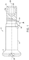
- FIG. 1 is a diagram representing a partially sectioned view of an interference fit bolt 2 (hereinafter "bolt 2").
- the bolt 2 comprises a head 4 designed to be countersunk into the structure and a shank 6 extending from the head 4.
- the head 4 has a drill center dimple 28.
- the shank 6 comprises an external surface that is circular cylindrical.
- the bolt 2 further comprises a threaded portion 8 comprising external threads 8a which is connected to the shank 6 by a transition portion 10 disposed between the shank 6 and the threaded portion 8.
- the threaded portion 8 has a hexagonal recess 20, in which an Allen key can be inserted during installation to hold the bolt 2 in place while a mating part is rotated about the external threads 8a.
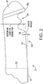
- FIG. 2 is a diagram representing a view of the portion of the bolt 2 within the dashed ellipse A depicted in FIG. 1 .
- the depicted portion of bolt 2 includes a portion of an incomplete thread 8b, which represents the start of the threaded portion 8.
- This view shows the geometry of the transition portion 10 in accordance the present invention.
- the transition portion 10 comprises a tapered lead-in section 14 that meets the shank 6 at a shank/lead-in intersection 22 (indicated by a straight vertical dashed line in FIG. 2 ) and a radiused lead-in section 16 that meets the tapered lead-in section 14.
- the transition portion 10 further comprises a transition section 24 between the radiused lead-in section 16 and the threaded portion 8.
- This transition section 24 has an external surface defined by an undulating curve rotated about the central axis 26 of bolt 2 and has diameters which are less than a minimum diameter D of the tapered lead-in section 14.
- the threaded portion 8 of bolt 2 has a maximum diameter which is less than the minimum diameter D.
- the tapered lead-in section 14 tapers gradually in a first axial direction toward the threaded portion 8 and has a first profile that is linear.
- the radiused tapered lead-in section 16 curves abruptly in the first axial direction and has a second profile that is a circular arc having a radius.
- the first and second profiles of the transition portion 10 are defined as follows.
- the first profile is a profile of an external surface of the tapered lead-in section 14 in a plane that intersects a central axis 26 of bolt 2.
- the second profile is an external surface of the radiused lead-in section 16 in the plane that intersects the central axis 26.
- the profile of the shank 6 in the plane that intersects the central axis 26 can be tangent to the first profile of the transition portion 10.
- the linearly tapered lead-in geometry of the tapered lead-in section 14 promotes gradual compression of material as the bolt 2 is pushed through the structures to be fastened.
- the taper length of the tapered lead-in section 14 may be in a range of 0.16 to 0.22 cm (0.062 to 0.092 inch) for bolts or pins having a shank diameter in a range of 0.5-1.3 cm (6/32 to 16/32 inch), the taper angle of the tapered lead-in section 14, as presently claimed, is 20 degrees or less, and the radius r of the radiused tapered lead-in section 16 may be about 0.03 cm (0.01 inch.
- An externally threaded fastener such as bolt 2 can be used to fasten a first structure having a first hole and a second structure having a second hole, the first and second holes having the same diameter.
- the method preferably comprises the following steps: placing the first and second structures together with the first and second holes aligned; inserting a threaded portion 8 of bolt 2 into the hole in the first structure until an edge of the hole in the first structure is in contact with and surrounds the tapered lead-in section 14; and forcing the bolt 2 further into the aligned holes of the first and second structures to cause the shank 6 to contact the edge of the hole in the first structure, push through the hole in the first structure, and then push through the hole in the second structure until the threaded portion 8 of bolt 2 projects beyond the second structure; and coupling a mating part to the threaded portion 8 of bolt 2.
- the tapered lead-in section 14 tapers gradually toward the threaded portion 8 and has a taper angle equal to or less than 20 degrees, while the shank 6 is circular cylindrical and has a diameter greater than the diameter of the first and second holes.
- an external surface of the tapered lead-in section 14 is a section of a right circular cone, A maximum diameter of the tapered lead-in section 14 equals the diameter of the shank 6 and a minimum diameter of the tapered lead-in section 16 is less than the diameters of the first and second holes.
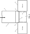
- FIG. 3 shows a portion of a bolt 2 being pushed into an interference hole 19 of a structure 18.
- the bolt 2 comprises a circular cylindrical shank 6 having a diameter greater than the diameter of the hole 19 in the structure 18 (one-half of the difference between the shank diameter and the hole diameter will be referred to below as the "amount of interference"), a tapered lead-in section 14, a radiused lead-in section 16 and a threaded portion 8 (the external threads are not shown in FIG. 3 ).
- a maximum diameter of the tapered lead-in section 14 equals the diameter of the shank 6 and a minimum diameter of the tapered lead-in section 14 is less than the diameter of the hole 19 in the structure 18.
- the hole 19 has an edge 21 which slides along the tapered lead-in section 14 as the bolt 2 is pushed into the interference hole 19. Edge 21 may be radiused. Depending on the amount of interference (preferably not in excess of 0.01 cm (0.004 inch) and the taper angle, the edge 21 of hole 19 will slide gradually along the tapered lead-in section 14 for a varying percentage of the taper length during bolt insertion. The gradual tapered angle of the tapered lead-in section 14 reduces the forces by approximately 136-227kg (300-500 lb), thereby reducing any potential damage to the structure 18.
- the bolt 2 will be pushed into the aligned interference holes of the structures to be fastened until the threaded portion 8 projects beyond the last structure.
- a mating part (not shown in FIG. 3 ) is then placed onto the threaded portion 8 with a specified clamping force.
- the mating part may take the form of a nut having an opening with internal threads and a non-circular wrenching surface (e.g., hexagonal) designed to be engaged by a wrench or similar tool.
- a variety of collars and nuts are compatible with the fasteners disclosed herein. Two examples of suitable collars will be described hereinafter with reference to FIGS. 4 and 5 .
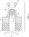
- FIG. 4 is a diagram representing a partially sectioned view of an assembly comprising a composite structure 30 and a metallic structure 32 gripped by a sleeveless interference fit fastener assembly in accordance with the present invention.
- the fastener assembly comprises an interference fit pin 34 (hereinafter "pin 34") having external threads and a remaining collar portion 36a having internal threads interengaged with the external threads of pin 34.
- pin 34 an interference fit pin 34
- FIG. 4 also shows a collar wrenching element 36b which, prior to separation from remaining collar portion 36a, was connected to remaining collar portion 36a.
- the collar wrenching element 36b has a non-circular wrenching surface (e.g., hexagonal) designed to be engaged by a wrench or similar tool, whereas the remaining collar portion 36a does not have a wrenching surface, thereby reducing the weight of the collar as compared to the weight of a nut.
- the external profile of the remaining collar portion 36a may be circular. This initial joinder of remaining collar portion 36a and collar wrenching element 36b (i.e., prior to the wrenching operation) to form a collar 36 indicated by the upper curly bracket in FIG. 4 .
- the pin 34 depicted in FIG. 4 comprises a shank 6, threaded portion 8 and transition portion 10 similar to the corresponding structures in bolt 2 seen in FIG. 1 . More specifically, the transition portion 10 comprises a tapered lead-in section 14 and a radiused lead-in section 16 having the geometry shown in FIG. 2 and the dimensions set forth above.
- FIG. 4 depicts a pin 34 having a protruding head 38, pin 34 may in the alternative have a countersunk (i.e., flush) head.
- a fastener assembly can be installed by one person from one side of the structures being fastened using power tools or hand tools. The procedure does not require calibrated torque wrenches and torque inspection.
- the collar 36 is screwed onto the threaded portion 8 of pin 34 and then tightened until a specified preload is produced on each fastener.
- the collar wrenching element 36b will break away at the designed preload, leaving the remaining collar portion 36a as seen in FIG. 4 .
- the elimination of the collar wrenching element 36b at torque-off results in weight savings of the fastener assembly.
- the fastener assembly can also be installed using a robotic system to insert and hammer the pin into the structure, and another robot or human tightens the collar from the other side of the structure.
- FIG. 5 is a diagram representing a partially sectioned view of an assembly comprising a composite structure 30 and a metallic structure 32 (referred to below as the "joint structure") gripped by a sleeveless interference fit fastener assembly in accordance with the present invention.
- This fastener assembly (which is frequently referred to as a lockbolt) comprises an interference fit pin 40 (hereinafter "pin 40") having external threads and a swaged collar 42 that is interengaged with the external threads of pin 40.
- the pin 40 may have external annular rings instead of external threads.
- the pin 40 depicted in FIG. 5 comprises a shank 6, a threaded portion 8 and a transition portion 10 similar to the corresponding structures in bolt 2 seen in FIG. 1 . More specifically, the transition portion 10 comprises a tapered lead-in section 14 and a radiused lead-in section 16 having the geometry shown in FIG. 2 and the dimensions stated above.
- FIG. 5 depicts a pin 40 having a countersunk (i.e., flush) head 44, pin 40 may in the alternative have a protruding head.
- the pin 40 shown in FIG. 5 is inserted into one side of the joint structure and the unswaged collar (not shown in FIG. 5 ) is placed over the pin 40 from the other side of the joint structure. Access to both sides of the joint structure is required.
- the unswaged collar in the form of a loose-fitting metal ring
- the pin 40 is connected to a pintail. Then a tool is engaged with the pintail.
- the bolts and pins disclosed herein are preferably made of a metal alloy such as titanium alloy, aluminum alloy, Inconel or corrosion-resistant steel.
- the collars disclosed herein are preferably made of titanium alloy, aluminum alloy or corrosion-resistant steel.
- the bolts, pins and collars are preferably coated or partially coated.
- the coating could be any combination of aluminum pigment coating, solid film lubricant, metallic plating (cadmium plate, zinc-nickel, etc.). Each coating could have an additional lubricant such as cetyl alcohol applied over the top.
- interference fit fasteners disclosed herein are especially useful in the assembly of composite wing structures during aircraft production.
- the proposed system has the following benefits over the existing systems.
- interference fit fasteners disclosed herein have advantages over sleeved bolts in that, by eliminating the sleeve element, the proposed fastener assembly reduces manufacturing complexity and decreases part cost. By installing these bolts or pins in interference, the assembly time is drastically reduced compared to the traditional sleeved bolt assembly process.
- the interference fit fasteners disclosed herein have advantages over installing clearance fit fasteners with cap seals in that fatigue results are improved_with interference fit fasteners compared to clearance fit fasteners. These fasteners are installed in the most fatigue-critical areas of the aircraft.
- the radii of fasteners in the industry are not optimized with the lead-in to promote interference fit in composite material (which may produce high installation forces due to the non-optimal lead-in geometry).
- the lead-in geometry proposed herein helps preclude fasteners from "sticking" in the hole or causing excessive damage to the structure during installation. Since this system does not need to add cap seals, the assembly time is decreased.
- the term “external projections” should be construed broadly to encompass at least the following types: (1) external threads and (2) external annular rings.
- the category “mating parts” comprises internally threaded nuts and collars and swaged collars.
- the term “fastener assembly” should be construed broadly to read on at least each of the following: (1) a bolt and a nut coupled to each other; (2) a bolt and a collar coupled to each other; (3) a pin and a collar coupled to each other; and (4) a pin and a nut coupled to each other.
Description
- This disclosure generally relates to the use of fasteners to secure two or more structures or workpieces (at least one of which is made of composite material, such as fiber-reinforced plastic) in a manner such that high interference fit of the fasteners within their respective holes in the layers is achieved. In particular, this disclosure relates to interference fit fastener assemblies comprising a bolt or a pin and a mating part (e.g., a nut or a collar) and not including a sleeve surrounding the fastener.
- Normal practice for fastening multiple layers of material together is to clamp up the layers, drill holes, and then insert some type of fastener into the holes and thereby secure the layers together. The fasteners are usually inserted in a net or clearance fit in the receiving holes in the layers. For many applications this will be sufficient. However, when the assembled structure is subjected to cyclic loading, the looseness of the fit of the fasteners within their holes will result in continual working of the fasteners within their holes. This in turn may lead to fretting and fatigue issues with either the fastener or the surrounding region of the layers adjacent a particular hole.
- To solve the foregoing problems, it is known that the utilization of a high interference fit of the fastener in the hole can effectively prevent the majority of this fretting due to cyclic loading of the assembled structure. High interference creates a tighter joint that reduces movement, resulting in enhanced fatigue performance. In many cases an oversized fastener will be driven directly into the receiving hole in the layers. Typically, some lubricant is applied to the fastener and hole before assembly to reduce the tendency toward abrasion as the fastener is pushed into the hole. In other cases a sleeve is slipped into the hole in a net or clearance fit followed by the drive-in of an oversized fastener with or without lubricant to radially expand the sleeve in order to create an interference fit condition.
- Currently there are two primary solutions for fasteners used in the assembly of composite wing structures in aircraft production: (1) sleeved bolt systems; and (2) clearance fit fasteners with cap seals. The use of sleeved bolt systems has the following drawbacks: (a) the parts require complicated installation methods; (b) the parts require careful handling to prevent damage; and (c) the system requires extensive in-process measurements (resulting in longer assembly time). The use of clearance fit fasteners with cap seals has the following drawbacks: (a) this system allows for increased joint deflection over time, affecting fatigue performance; and (b) the amount of time involved in seal cap application increases assembly time. In addition, existing interference fit solutions used in metallic aircraft structure may not be optimized to reduce the installation force load when a fastener is installed. A high installation force load may cause composite material to crack or excessively delaminate.
- It would be desirable to provide improved interference fit fasteners for installation in composite material which reduce installation force loads and address one or more of the drawbacks identified in the preceding paragraph.
- Patent document
US 2015/337885 A1 , in accordance with its abstract, states: a fastener system for composite structure providing electromagnetic energy protection has a shank with a threaded portion on a first end of the shank terminating in a lead-in portion. A head is present on a second end of the shank. The shank is adapted for intimate conductive contact with an inner surface of an interference fit hole. -
Patent document EP 1 903 221 A2 , in accordance with its abstract, states: a fastener adapted to pass through aligned holes through workpieces is disclosed. The fastener includes a pin member having a transition portion wherein the diameter of the transition portion decreases radially as it extends from the smooth cylindrical shank portion to the threaded portion. The fastener may also comprise a sleeve member and a clamping means. The clamping means includes a collar, a nut, or any other possible clamping means. In exemplary embodiments, the workpieces can be formed with a plurality of materials, the materials including composite, metallic, or composite/metallic structures, any combination thereof. In particular embodiments, the fastener has interference capability of 0,013 to 0,25 mm in composite structures without risk of composite delamination or damage. - The presently claimed invention is set out in the appended set of claims.
- The subject matter disclosed in detail below is directed to interference fit fasteners for attaching two or more structures together. Each interference fit fastener comprises a fastener having external projections that has a tapered lead-in section between the shank and the mating portion. The taper can be linear, meaning that the external surface of the tapered lead-in section will be a section of a right circular cone. This linearly tapered lead-in geometry decreases installation forces in interference fit holes, thereby increasing joint fatigue life, enhancing fluid tightness, and reducing susceptibility to electromagnetic effects. A linearly tapered lead-in geometry accomplishes the foregoing by promoting gradual compression of material as the bolt is pushed through the structures to be fastened.
- The interference fit fastener, as presently claimed, comprises a fastener having a transition portion disposed between a shank and a mating portion having external projections, which transition portion comprises a tapered lead-in section that meets the shank at a shank/lead-in intersection and a radiused tapered lead-in section that meets the tapered lead-in section. The tapered lead-in section tapers gradually in a first axial direction toward the mating portion and has a first profile that is linear and a taper angle equal to or less than 20 degrees, and the radiused lead-in section curves abruptly in the first axial direction and has a second profile that is a circular arc having a radius.
- As used herein, the term "external projections" should be construed broadly to encompass at least the following types: (1) external threads and (2) external annular rings. For the purpose of illustration, examples of fasteners having externals threads are described below. However, the concepts disclosed and claimed herein also have application to interference fit fasteners having external annular rings. Thus the subject matter disclosed in detail below may be characterized by one or more of the following aspects.
- One aspect of the subject matter disclosed in detail below is a method for fastening a first structure having a first hole and a second structure having a second hole, the first and second holes having the same diameter, comprising: placing the first and second structures together with the first and second holes aligned; inserting a mating portion of a fastener into the hole in the first structure until an edge of the hole in the first structure is in contact with and surrounds a tapered lead-in section of the fastener that tapers gradually toward the mating portion and has a taper angle equal to or less than 20 degrees, the fastener further comprising a head and a circular cylindrical shank connecting the head to the tapered lead-in section, the shank having a diameter greater than the diameter of the holes; and forcing the fastener further into the aligned first and second holes to cause the shank to contact the edge of the first hole, push through the first hole, and then push through the second hole until the mating portion of the fastener projects beyond the second structure; and coupling a mating part to the mating portion of the fastener. An external surface of the tapered lead-in section can be a section of a right circular cone, a maximum diameter of the tapered lead-in section equals the diameter of the shank and a minimum diameter of the tapered lead-in section is less than the diameter of the first and second holes. The fastener, as presently claimed, further comprises a radiused lead-in section that meets the tapered lead-in section, curves abruptly toward the mating portion and has a second profile that is a circular arc having a radius, wherein the mating portion has a maximum diameter less than a minimum diameter of the radiused lead-in section.
- Another aspect of the subject matter disclosed herein is a method for fastening a first structure having a first hole and a second structure having a second hole, the first and second holes having the same hole diameter, comprising: placing the first and second structures together with the first and second holes aligned; inserting a mating portion of a fastener into the first hole until an edge of the first hole in the first structure is in contact with and surrounds a tapered lead-in section of the fastener that tapers gradually toward the mating portion, the fastener further comprising a head and a circular cylindrical shank connecting the head to the tapered lead-in section, the shank having a shank diameter greater than the hole diameter, and the amount of interference between the shank and the first hole being no more than 0.01 cm(0.004 inch); forcing the fastener further into the aligned holes of the first and second structures to cause the shank to contact the edge of the first hole, push through the first hole, and then push through the second hole until the mating portion of the fastener projects beyond the second structure; and coupling a mating part to the mating portion of the fastener.
- A further aspect of the subject matter disclosed herein is a fastener assembly comprising a fastener and a mating part coupled to the fastener, wherein the fastener comprises: a head; a shank extending from the head, the shank comprising an external surface that is circular cylindrical and has a shank diameter in a range of 0.5-1.3 cm (6/32 to 16/32 inch); a mating portion comprising external projections; and a transition portion disposed between the shank and the mating portion, wherein the transition portion comprises a tapered lead-in section that meets the shank at a shank/lead-in intersection and a radiused lead-in section that meets the tapered lead-in section. As in the first aspect, the tapered lead-in section tapers gradually in a first axial direction toward the mating portion and has a first profile that is linear, a taper length in a range of 0.16 to 0.22 cm (0.062 to 0.092 inch), and a taper angle equal to or less than 20 degrees, and the radiused lead-in section curves abruptly in the first axial direction and has a second profile that is a circular arc having a radius.
- The fastener may comprise a bolt and the mating part comprises a nut having internal threads that are interengaged with the external projections of the mating portion of the bolt. The fastener may comprise a pin and the mating part comprises a collar that is interengaged with the external projections of the mating portion of the pin.
- Yet another aspect of the subject matter disclosed herein is an assembly comprising a first structural element having a first hole, a second structural element having a second hole aligned with the first hole of the first structural element, a fastener that occupies at least respective portions of the holes in the first and second structural elements without a surrounding sleeve and extends beyond the second structural element, and a mating part that abuts the second structural element and is coupled to the fastener, wherein the fastener comprises: a head; a shank extending from the head, the shank comprising an external surface that is circular cylindrical; a mating portion comprising external projections; and a transition portion disposed between the shank and the mating portion, wherein the transition portion comprises a tapered lead-in section that meets the shank at a shank/lead-in intersection and a radiused lead-in section that meets the tapered lead-in section. The tapered lead-in section tapers gradually in a first axial direction toward the mating portion and has a first profile that is linear and a taper angle equal to or less than 20 degrees, and the radiused lead-in section curves abruptly in the first axial direction and has a second profile that is a circular arc having a radius. One of the first and second structural elements can be made of composite material and the other of the first and second structural elements can be made of metallic material. Both structural elements can be made of composite material. The fastener and the first and second structural elements are in contact without a sleeve therebetween.
- Other aspects of improved interference fit fasteners for attaching two or more structures to each other are disclosed below.
-
-
FIG. 1 is a diagram representing a partially sectioned view of an interference fit bolt. -
FIG. 2 is a diagram representing a view of the portion of the interference fit bolt within the dashed ellipse A depicted inFIG. 1 , which view shows the geometry of a tapered lead-in section in accordance with the present invention. -
FIG. 3 is a diagram showing a sectional view of a portion of an interference fit bolt being pushed into an interference hole of a structure. -
FIG. 4 is a diagram representing a partially sectioned view of an assembly comprising composite and metallic structures gripped by a sleeveless interference fit fastener assembly in accordance with the present invention, which fastener assembly comprises a pin having external threads and a collar having internal threads interengaged with the external threads. -
FIG. 5 is a diagram representing a partially sectioned view of an assembly comprising composite and metallic structures gripped by a sleeveless interference fit fastener assembly in accordance with the present invention, which fastener assembly comprises a pin having external threads and a swaged collar interengaged with the external threads. - Reference will hereinafter be made to the drawings in which similar elements in different drawings bear the same reference numerals.
- An interference fit fastener will now be described in detail for the purpose of illustration. At least some of the details disclosed below relate to optional features or aspects, which in some applications may be omitted without departing from the scope of the claims appended hereto.
- In particular, an interference fit fastener for attaching two structures to each other is described in some detail below. In the examples given below, one of the structures is made of metallic material (e.g., a metal alloy) and the other structure is made of composite material (e.g., fiber-reinforced plastic). However, in alternative examples, both structures can be made of composite material or both structures can be made of metallic material. In addition, it should be appreciated that the concept disclosed herein also has application in the attachment of three or more structures together.
-
FIG. 1 is a diagram representing a partially sectioned view of an interference fit bolt 2 (hereinafter "bolt 2"). Thebolt 2 comprises a head 4 designed to be countersunk into the structure and ashank 6 extending from the head 4. The head 4 has adrill center dimple 28. Theshank 6 comprises an external surface that is circular cylindrical. Thebolt 2 further comprises a threadedportion 8 comprisingexternal threads 8a which is connected to theshank 6 by atransition portion 10 disposed between theshank 6 and the threadedportion 8. The threadedportion 8 has ahexagonal recess 20, in which an Allen key can be inserted during installation to hold thebolt 2 in place while a mating part is rotated about theexternal threads 8a. -
FIG. 2 is a diagram representing a view of the portion of thebolt 2 within the dashed ellipse A depicted inFIG. 1 . The depicted portion ofbolt 2 includes a portion of anincomplete thread 8b, which represents the start of the threadedportion 8. This view shows the geometry of thetransition portion 10 in accordance the present invention. Thetransition portion 10 comprises a tapered lead-insection 14 that meets theshank 6 at a shank/lead-in intersection 22 (indicated by a straight vertical dashed line inFIG. 2 ) and a radiused lead-insection 16 that meets the tapered lead-insection 14. Thetransition portion 10 further comprises atransition section 24 between the radiused lead-insection 16 and the threadedportion 8. Thistransition section 24 has an external surface defined by an undulating curve rotated about thecentral axis 26 ofbolt 2 and has diameters which are less than a minimum diameter D of the tapered lead-insection 14. In addition, the threadedportion 8 ofbolt 2 has a maximum diameter which is less than the minimum diameter D. - The tapered lead-in
section 14 tapers gradually in a first axial direction toward the threadedportion 8 and has a first profile that is linear. The radiused tapered lead-insection 16 curves abruptly in the first axial direction and has a second profile that is a circular arc having a radius. - For the avoidance of doubt, the first and second profiles of the
transition portion 10 are defined as follows. The first profile is a profile of an external surface of the tapered lead-insection 14 in a plane that intersects acentral axis 26 ofbolt 2. The second profile is an external surface of the radiused lead-insection 16 in the plane that intersects thecentral axis 26. The profile of theshank 6 in the plane that intersects thecentral axis 26 can be tangent to the first profile of thetransition portion 10. The linearly tapered lead-in geometry of the tapered lead-insection 14 promotes gradual compression of material as thebolt 2 is pushed through the structures to be fastened. - It should be appreciated that the dimensions of
bolt 2 will vary depending on the thicknesses of the structures being fastened together and the diameters of the aligned holes in those structures. In accordance with various examples, the taper length of the tapered lead-insection 14 may be in a range of 0.16 to 0.22 cm (0.062 to 0.092 inch) for bolts or pins having a shank diameter in a range of 0.5-1.3 cm (6/32 to 16/32 inch), the taper angle of the tapered lead-insection 14, as presently claimed, is 20 degrees or less, and the radius r of the radiused tapered lead-insection 16 may be about 0.03 cm (0.01 inch. The relationship between the length L of the tapered lead-insection 16 and the shank diameter D can be expressed as the following function: D = - 0.4578 + 10.443L. - An externally threaded fastener such as
bolt 2 can be used to fasten a first structure having a first hole and a second structure having a second hole, the first and second holes having the same diameter. The method preferably comprises the following steps: placing the first and second structures together with the first and second holes aligned; inserting a threadedportion 8 ofbolt 2 into the hole in the first structure until an edge of the hole in the first structure is in contact with and surrounds the tapered lead-insection 14; and forcing thebolt 2 further into the aligned holes of the first and second structures to cause theshank 6 to contact the edge of the hole in the first structure, push through the hole in the first structure, and then push through the hole in the second structure until the threadedportion 8 ofbolt 2 projects beyond the second structure; and coupling a mating part to the threadedportion 8 ofbolt 2. As previously described, the tapered lead-insection 14 tapers gradually toward the threadedportion 8 and has a taper angle equal to or less than 20 degrees, while theshank 6 is circular cylindrical and has a diameter greater than the diameter of the first and second holes. an external surface of the tapered lead-insection 14 is a section of a right circular cone, A maximum diameter of the tapered lead-insection 14 equals the diameter of theshank 6 and a minimum diameter of the tapered lead-insection 16 is less than the diameters of the first and second holes. - During installation, a manual rivet gun or automated system can be used to hammer the
bolt 2 into aligned holes of the structures to be fastened.FIG. 3 shows a portion of abolt 2 being pushed into aninterference hole 19 of astructure 18. Thebolt 2 comprises a circularcylindrical shank 6 having a diameter greater than the diameter of thehole 19 in the structure 18 (one-half of the difference between the shank diameter and the hole diameter will be referred to below as the "amount of interference"), a tapered lead-insection 14, a radiused lead-insection 16 and a threaded portion 8 (the external threads are not shown inFIG. 3 ). A maximum diameter of the tapered lead-insection 14 equals the diameter of theshank 6 and a minimum diameter of the tapered lead-insection 14 is less than the diameter of thehole 19 in thestructure 18. Thehole 19 has anedge 21 which slides along the tapered lead-insection 14 as thebolt 2 is pushed into theinterference hole 19.Edge 21 may be radiused. Depending on the amount of interference (preferably not in excess of 0.01 cm (0.004 inch) and the taper angle, theedge 21 ofhole 19 will slide gradually along the tapered lead-insection 14 for a varying percentage of the taper length during bolt insertion. The gradual tapered angle of the tapered lead-insection 14 reduces the forces by approximately 136-227kg (300-500 lb), thereby reducing any potential damage to thestructure 18. - The
bolt 2 will be pushed into the aligned interference holes of the structures to be fastened until the threadedportion 8 projects beyond the last structure. A mating part (not shown inFIG. 3 ) is then placed onto the threadedportion 8 with a specified clamping force. In some cases, the mating part may take the form of a nut having an opening with internal threads and a non-circular wrenching surface (e.g., hexagonal) designed to be engaged by a wrench or similar tool. It should be appreciated, however, that a variety of collars and nuts are compatible with the fasteners disclosed herein. Two examples of suitable collars will be described hereinafter with reference toFIGS. 4 and5 . -
FIG. 4 is a diagram representing a partially sectioned view of an assembly comprising acomposite structure 30 and ametallic structure 32 gripped by a sleeveless interference fit fastener assembly in accordance with the present invention. The fastener assembly comprises an interference fit pin 34 (hereinafter "pin 34") having external threads and a remainingcollar portion 36a having internal threads interengaged with the external threads ofpin 34.FIG. 4 also shows acollar wrenching element 36b which, prior to separation from remainingcollar portion 36a, was connected to remainingcollar portion 36a. Thecollar wrenching element 36b has a non-circular wrenching surface (e.g., hexagonal) designed to be engaged by a wrench or similar tool, whereas the remainingcollar portion 36a does not have a wrenching surface, thereby reducing the weight of the collar as compared to the weight of a nut. For example, the external profile of the remainingcollar portion 36a may be circular. This initial joinder of remainingcollar portion 36a andcollar wrenching element 36b (i.e., prior to the wrenching operation) to form acollar 36 indicated by the upper curly bracket inFIG. 4 . - Although not shown in detail, the
pin 34 depicted inFIG. 4 comprises ashank 6, threadedportion 8 andtransition portion 10 similar to the corresponding structures inbolt 2 seen inFIG. 1 . More specifically, thetransition portion 10 comprises a tapered lead-insection 14 and a radiused lead-insection 16 having the geometry shown inFIG. 2 and the dimensions set forth above. AlthoughFIG. 4 depicts apin 34 having a protrudinghead 38,pin 34 may in the alternative have a countersunk (i.e., flush) head. - The procedure for installing fastener assemblies of the type depicted in
FIG. 4 is well known. Such a fastener assembly can be installed by one person from one side of the structures being fastened using power tools or hand tools. The procedure does not require calibrated torque wrenches and torque inspection. Thecollar 36 is screwed onto the threadedportion 8 ofpin 34 and then tightened until a specified preload is produced on each fastener. Thecollar wrenching element 36b will break away at the designed preload, leaving the remainingcollar portion 36a as seen inFIG. 4 . The elimination of thecollar wrenching element 36b at torque-off results in weight savings of the fastener assembly. The fastener assembly can also be installed using a robotic system to insert and hammer the pin into the structure, and another robot or human tightens the collar from the other side of the structure. -
FIG. 5 is a diagram representing a partially sectioned view of an assembly comprising acomposite structure 30 and a metallic structure 32 (referred to below as the "joint structure") gripped by a sleeveless interference fit fastener assembly in accordance with the present invention. This fastener assembly (which is frequently referred to as a lockbolt) comprises an interference fit pin 40 (hereinafter "pin 40") having external threads and a swagedcollar 42 that is interengaged with the external threads of pin 40.Thepin 40 may have external annular rings instead of external threads. - Although not shown in detail, the
pin 40 depicted inFIG. 5 comprises ashank 6, a threadedportion 8 and atransition portion 10 similar to the corresponding structures inbolt 2 seen inFIG. 1 . More specifically, thetransition portion 10 comprises a tapered lead-insection 14 and a radiused lead-insection 16 having the geometry shown inFIG. 2 and the dimensions stated above. AlthoughFIG. 5 depicts apin 40 having a countersunk (i.e., flush)head 44,pin 40 may in the alternative have a protruding head. - The
pin 40 shown inFIG. 5 is inserted into one side of the joint structure and the unswaged collar (not shown inFIG. 5 ) is placed over thepin 40 from the other side of the joint structure. Access to both sides of the joint structure is required. During the installation cycle of a lockbolt, the unswaged collar (in the form of a loose-fitting metal ring) is deformed around thepin 40, which has locking grooves on the threadedportion 8. Although not shown inFIG. 5 , it is well known that at the start of a typical lockbolt installation procedure, thepin 40 is connected to a pintail. Then a tool is engaged with the pintail. Thereafter thepin head 44 is pulled against themetallic structure 32 and the unswaged collar is pushed against thecomposite structure 30, pulling thecomposite structure 30 andmetallic structure 32 together. Then a conical cavity of the tool is forced down the collar, which reduces the diameter of collar and progressively swages the collar material into the grooves of theharder pin 40, thereby forming swagedcollar 42. As the force required for swaging increases during the process, the installation is completed when the pintail (not shown) breaks off. Thepin 40 and swagedcollar 42 combine to form the fastener assembly. - The bolts and pins disclosed herein are preferably made of a metal alloy such as titanium alloy, aluminum alloy, Inconel or corrosion-resistant steel. The collars disclosed herein are preferably made of titanium alloy, aluminum alloy or corrosion-resistant steel. The bolts, pins and collars are preferably coated or partially coated. The coating could be any combination of aluminum pigment coating, solid film lubricant, metallic plating (cadmium plate, zinc-nickel, etc.). Each coating could have an additional lubricant such as cetyl alcohol applied over the top.
- The interference fit fasteners disclosed herein are especially useful in the assembly of composite wing structures during aircraft production. The proposed system has the following benefits over the existing systems.
- The interference fit fasteners disclosed herein have advantages over sleeved bolts in that, by eliminating the sleeve element, the proposed fastener assembly reduces manufacturing complexity and decreases part cost. By installing these bolts or pins in interference, the assembly time is drastically reduced compared to the traditional sleeved bolt assembly process.
- The interference fit fasteners disclosed herein have advantages over installing clearance fit fasteners with cap seals in that fatigue results are improved_with interference fit fasteners compared to clearance fit fasteners. These fasteners are installed in the most fatigue-critical areas of the aircraft. Currently, the radii of fasteners in the industry are not optimized with the lead-in to promote interference fit in composite material (which may produce high installation forces due to the non-optimal lead-in geometry). The lead-in geometry proposed herein helps preclude fasteners from "sticking" in the hole or causing excessive damage to the structure during installation. Since this system does not need to add cap seals, the assembly time is decreased.
- While interference fit fasteners for attaching two structures to each other have been described with reference to various embodiments, it will be understood by those skilled in the art that various changes may be made and equivalents may be substituted for elements thereof without departing from the scope of the claims set forth hereinafter. In addition, many modifications may be made to adapt the teachings herein to a particular situation without departing from the scope of the claims.
- As used in the claims, the term "external projections" should be construed broadly to encompass at least the following types: (1) external threads and (2) external annular rings. As used in the claims, the category "mating parts" comprises internally threaded nuts and collars and swaged collars. As used in the claims, the term "fastener assembly" should be construed broadly to read on at least each of the following: (1) a bolt and a nut coupled to each other; (2) a bolt and a collar coupled to each other; (3) a pin and a collar coupled to each other; and (4) a pin and a nut coupled to each other.
Claims (12)
- A method for fastening a first structure having a first hole and a second structure having a second hole, the first and second holes having a same diameter, comprising:placing the first and second structures together with the first and second holes aligned;inserting a mating portion (8) of a fastener (2) into the first hole until an edge (21) of the first hole (19) in the first structure (18) is in direct contact with and surrounds a tapered lead-in section (14) of the fastener (2) that tapers gradually toward the mating portion (8) and has a taper angle equal to or less than 20 degrees, the fastener (2) further comprising a head (4) and a circular cylindrical shank (6) connecting the head (4) to the tapered lead-in section (14), the shank (6) having a diameter greater than the diameter of the first and second holes, wherein the fastener (2) further comprises a radiused lead-in section (16) that meets the tapered lead-in section (14), curves abruptly toward the mating portion (8) and has a second profile that is a circular arc having a radius and a maximum diameter equaling a minimum diameter of the tapered lead-in section (14), and wherein the mating portion (8) has a maximum diameter less than a minimum diameter of the radiused lead-in section (16);forcing the fastener (2) further into the aligned holes of the first and second structures to cause the shank (6) to directly contact the edge (21) of the first hole, push through the first hole (19), and then push through the second hole until the mating portion (8) of the fastener (2) projects beyond the second structure; andcoupling a mating part (36, 42) to the mating portion (8) of the fastener (2).
- The method as recited in claim 1, wherein an external surface of the tapered lead-in section (14) is a section of a right circular cone.
- The method as recited in claim 1 or 2, wherein a maximum diameter of the tapered lead-in section (14) equals the diameter of the shank (6) and the minimum diameter of the tapered lead-in section (14) is less than the diameter of the first and second holes.
- A fastening assembly comprising a first structural element having a first hole, a second structural element having a second hole aligned with the first hole of the first structural element, a fastener (34, 40) according to claim 11 that occupies at least respective portions of the first and second holes in the first and second structural elements without a surrounding sleeve and extends beyond the second structural element, and a mating part (36, 42) that abuts the second structural element and is coupled to the fastener (34, 40).
- The assembly as recited in claim 4, wherein the shank (6) of the fastener (34, 40) and the first and second structural elements are in contact without a sleeve therebetween.
- The assembly as recited in claim 4 or 5, wherein one of the first and second structural elements is a composite structure (30) and the other of the first and second structural elements is a metallic structure (32).
- The assembly as recited in claim 4, 5, or 6, wherein the mating part (36, 42) comprises internal threads that are interengaged with the external projections of the mating portion (8) of the fastener (34, 40).
- The assembly as recited in one of claims 4 to 7, wherein the mating part (36, 42) comprises a swaged collar (42) that is interengaged with the external projections of the mating portion (8) of the fastener (34, 40).
- The assembly as recited in one of the claims 4 to 8, wherein the first profile is a profile of an external surface of the tapered lead-in section (14) in a plane that intersects a central axis (26) of the fastener (34, 40), and the second profile is an external surface of the radiused lead-in section (16) in the plane that intersects the central axis (26) of the fastener (34, 40).
- The assembly as recited in one of the claims 4 to 9, wherein a maximum diameter of the tapered lead-in section (14) equals a diameter of the shank (6) and an external surface of the tapered lead-in section (14) is a section of a right circular cone.
- A fastener (34, 40) for securing two or more structures such as composite aircraft wing structures together, the fastener comprising:a head (38, 44);a shank (6) extending from the head (38, 44), the shank (6) comprising an external surface that is circular cylindrical;a mating portion (8) comprising external projections; anda transition portion (10) disposed between the shank (6) and the mating portion (8),wherein the transition portion (10) comprises a tapered lead-in section (14) that meets the shank (6) at a shank/lead-in intersection (22) and a radiused lead-in section (16) that meets the tapered lead-in section (14), the tapered lead-in section (14) tapers gradually in a first axial direction toward the mating portion (8) and has a first profile that is linear and a taper angle equal to or less than 20 degrees, and the radiused lead-in section (16) curves abruptly in the first axial direction and has a second profile that is a circular arc having a radius and a maximum diameter equaling a minimum diameter of the tapered lead-in section (14),wherein the mating portion (8) has a maximum diameter less than a minimum diameter of the radiused lead-in section (16).
- Use of a fastener according to claim 11 for securing two composite aircraft wing structures together.
Applications Claiming Priority (1)
| Application Number | Priority Date | Filing Date | Title |
|---|---|---|---|
| US15/437,234 US10711814B2 (en) | 2017-02-20 | 2017-02-20 | Tapered lead-in for interference fit fasteners |
Publications (2)
| Publication Number | Publication Date |
|---|---|
| EP3364050A1 EP3364050A1 (en) | 2018-08-22 |
| EP3364050B1 true EP3364050B1 (en) | 2021-02-24 |
Family
ID=60654645
Family Applications (1)
| Application Number | Title | Priority Date | Filing Date |
|---|---|---|---|
| EP17204423.2A Active EP3364050B1 (en) | 2017-02-20 | 2017-11-29 | Tapered lead-in for interference fit fasteners |
Country Status (6)
| Country | Link |
|---|---|
| US (2) | US10711814B2 (en) |
| EP (1) | EP3364050B1 (en) |
| JP (1) | JP7145604B2 (en) |
| KR (1) | KR102557852B1 (en) |
| CN (1) | CN108457960B (en) |
| CA (2) | CA3179088A1 (en) |
Families Citing this family (12)
| Publication number | Priority date | Publication date | Assignee | Title |
|---|---|---|---|---|
| EP3491257B1 (en) * | 2016-08-01 | 2023-03-29 | Coskun, Kenan | A connection system |
| US10711814B2 (en) * | 2017-02-20 | 2020-07-14 | The Boeing Company | Tapered lead-in for interference fit fasteners |
| WO2019226144A1 (en) * | 2018-05-21 | 2019-11-28 | Arconic Inc. | Fastener including a transition zone and method of use thereof |
| US10711815B2 (en) | 2018-09-20 | 2020-07-14 | The Boeing Company | Indexing pins, indexing clamps, and methods of aligning a first body and a second body of a structure |
| US10690160B2 (en) | 2018-09-20 | 2020-06-23 | The Boeing Company | Methods of aligning a first body and a second body of a structure |
| US11225989B2 (en) * | 2018-09-20 | 2022-01-18 | The Boeing Company | Indexing pins and indexing clamps for aligning a first body and a second body of a structure |
| EP3921552A4 (en) * | 2019-02-07 | 2022-08-24 | Howmet Aerospace Inc. | Blind fastener and method of installation thereof |
| US20200291979A1 (en) * | 2019-03-15 | 2020-09-17 | Roller Bearing Company Of America, Inc. | Bolt interface coating and thread transition geometry for sleeved fasteners used in composite applications |
| CN110566566B (en) * | 2019-09-17 | 2022-01-04 | 青岛交建集团有限公司 | Novel protection device based on road and bridge protection |
| US20230235770A1 (en) * | 2020-05-27 | 2023-07-27 | Volvo Truck Corporation | A fastening element and a vehicle arrangement |
| CN114876968B (en) * | 2022-07-12 | 2022-10-11 | 四川工程职业技术学院 | Connecting structure of positioning cone |
| DE102022121435A1 (en) * | 2022-08-24 | 2024-02-29 | Ejot Se & Co. Kg | Screw for direct screwing into a component |
Family Cites Families (13)
| Publication number | Priority date | Publication date | Assignee | Title |
|---|---|---|---|---|
| US5018920A (en) | 1989-01-23 | 1991-05-28 | Mcdonnell Douglas Corporation | Interference fit bolt and sleeve |
| US6149363A (en) | 1998-10-29 | 2000-11-21 | Huck International, Inc. | Lightweight threaded fastener and thread rolling die |
| SE527767C2 (en) | 2004-10-22 | 2006-05-30 | Volvo Lastvagnar Ab | Fasteners |
| US7695226B2 (en) * | 2006-09-21 | 2010-04-13 | Alcoa Global Fasteners, Inc. | High performance sleeved interference fasteners for composite applications |
| US8312606B2 (en) * | 2007-10-16 | 2012-11-20 | Fatigue Technology, Inc. | Expandable fastener assembly with deformed collar |
| US9289815B2 (en) * | 2011-12-29 | 2016-03-22 | Standard Lifters, Inc. | Modular pilot assembly with self-contained stripper and method for metal forming dies |
| FR3008754B1 (en) | 2013-07-19 | 2015-09-04 | Lisi Aerospace | METAL FASTENING |
| FR3013781A1 (en) * | 2013-11-25 | 2015-05-29 | Airbus Operations Sas | FIXING ELEMENT FOR PARTS OF AN ASSEMBLY |
| US9908637B2 (en) * | 2014-05-23 | 2018-03-06 | The Boeing Company | Modified shank fasteners for electromagnetic effect (EME) technology |
| FR3026446B1 (en) * | 2014-09-30 | 2017-12-01 | Lisi Aerospace | LUBRICATED INTERFERENCE FASTENING |
| CN204312500U (en) * | 2014-11-24 | 2015-05-06 | 玉环精工机械制造有限公司 | A kind of connecting-rod bolts |
| US10711814B2 (en) * | 2017-02-20 | 2020-07-14 | The Boeing Company | Tapered lead-in for interference fit fasteners |
| US10641307B2 (en) * | 2017-02-20 | 2020-05-05 | The Boeing Company | Radiused lead-in for interference fit fasteners |
-
2017
- 2017-02-20 US US15/437,234 patent/US10711814B2/en active Active
- 2017-11-21 JP JP2017223418A patent/JP7145604B2/en active Active
- 2017-11-29 EP EP17204423.2A patent/EP3364050B1/en active Active
- 2017-12-11 CA CA3179088A patent/CA3179088A1/en active Pending
- 2017-12-11 CA CA2988522A patent/CA2988522C/en active Active
- 2017-12-15 CN CN201711345501.3A patent/CN108457960B/en active Active
- 2017-12-21 KR KR1020170177383A patent/KR102557852B1/en active IP Right Grant
-
2020
- 2020-06-16 US US16/902,378 patent/US11168721B2/en active Active
Non-Patent Citations (1)
| Title |
|---|
| None * |
Also Published As
| Publication number | Publication date |
|---|---|
| US20200309173A1 (en) | 2020-10-01 |
| CA2988522A1 (en) | 2018-08-20 |
| US20180238361A1 (en) | 2018-08-23 |
| KR20180096487A (en) | 2018-08-29 |
| JP7145604B2 (en) | 2022-10-03 |
| JP2018136022A (en) | 2018-08-30 |
| US11168721B2 (en) | 2021-11-09 |
| CN108457960B (en) | 2021-07-30 |
| EP3364050A1 (en) | 2018-08-22 |
| CN108457960A (en) | 2018-08-28 |
| US10711814B2 (en) | 2020-07-14 |
| KR102557852B1 (en) | 2023-07-19 |
| CA3179088A1 (en) | 2018-08-20 |
| CA2988522C (en) | 2023-02-28 |
Similar Documents
| Publication | Publication Date | Title |
|---|---|---|
| EP3364050B1 (en) | Tapered lead-in for interference fit fasteners | |
| US10641307B2 (en) | Radiused lead-in for interference fit fasteners | |
| US10294976B2 (en) | Method of installing a structural blind fastener | |
| JP5236504B2 (en) | Mechanically locked blind bolt fastener | |
| CA2183450C (en) | Blind fastener with deformable sleeve | |
| US8348566B2 (en) | Blind fastener | |
| US20070243037A1 (en) | Blind bolt fastener | |
| US10267347B2 (en) | Blind fastener | |
| US9284971B2 (en) | Fastener and method of installing same | |
| US9061379B1 (en) | Grommet installation tool | |
| US11585364B2 (en) | Blind fastener | |
| US20130061452A1 (en) | Fastener and method of installing same | |
| US20140201974A1 (en) | Method of removing a wrenching means from a blind fastener | |
| GB2252125A (en) | Interference fit stud fastening. | |
| US8579567B2 (en) | Device for blind fixation | |
| US20230112581A1 (en) | Multi-piece fastener comprising a tapered threaded portion and method of fastening | |
| US20190032695A1 (en) | Internal positive stop, break-off flushness in blind fasteners | |
| CA1043547A (en) | Method of preloading and crimping fasteners |
Legal Events
| Date | Code | Title | Description |
|---|---|---|---|
| PUAI | Public reference made under article 153(3) epc to a published international application that has entered the european phase |
Free format text: ORIGINAL CODE: 0009012 |
|
| STAA | Information on the status of an ep patent application or granted ep patent |
Free format text: STATUS: REQUEST FOR EXAMINATION WAS MADE |
|
| 17P | Request for examination filed |
Effective date: 20171129 |
|
| AK | Designated contracting states |
Kind code of ref document: A1 Designated state(s): AL AT BE BG CH CY CZ DE DK EE ES FI FR GB GR HR HU IE IS IT LI LT LU LV MC MK MT NL NO PL PT RO RS SE SI SK SM TR |
|
| AX | Request for extension of the european patent |
Extension state: BA ME |
|
| STAA | Information on the status of an ep patent application or granted ep patent |
Free format text: STATUS: EXAMINATION IS IN PROGRESS |
|
| 17Q | First examination report despatched |
Effective date: 20190902 |
|
| GRAP | Despatch of communication of intention to grant a patent |
Free format text: ORIGINAL CODE: EPIDOSNIGR1 |
|
| STAA | Information on the status of an ep patent application or granted ep patent |
Free format text: STATUS: GRANT OF PATENT IS INTENDED |
|
| INTG | Intention to grant announced |
Effective date: 20200416 |
|
| GRAJ | Information related to disapproval of communication of intention to grant by the applicant or resumption of examination proceedings by the epo deleted |
Free format text: ORIGINAL CODE: EPIDOSDIGR1 |
|
| STAA | Information on the status of an ep patent application or granted ep patent |
Free format text: STATUS: EXAMINATION IS IN PROGRESS |
|
| INTC | Intention to grant announced (deleted) | ||
| GRAP | Despatch of communication of intention to grant a patent |
Free format text: ORIGINAL CODE: EPIDOSNIGR1 |
|
| STAA | Information on the status of an ep patent application or granted ep patent |
Free format text: STATUS: GRANT OF PATENT IS INTENDED |
|
| INTG | Intention to grant announced |
Effective date: 20200921 |
|
| GRAS | Grant fee paid |
Free format text: ORIGINAL CODE: EPIDOSNIGR3 |
|
| GRAA | (expected) grant |
Free format text: ORIGINAL CODE: 0009210 |
|
| STAA | Information on the status of an ep patent application or granted ep patent |
Free format text: STATUS: THE PATENT HAS BEEN GRANTED |
|
| AK | Designated contracting states |
Kind code of ref document: B1 Designated state(s): AL AT BE BG CH CY CZ DE DK EE ES FI FR GB GR HR HU IE IS IT LI LT LU LV MC MK MT NL NO PL PT RO RS SE SI SK SM TR |
|
| REG | Reference to a national code |
Ref country code: CH Ref legal event code: EP |
|
| REG | Reference to a national code |
Ref country code: AT Ref legal event code: REF Ref document number: 1364788 Country of ref document: AT Kind code of ref document: T Effective date: 20210315 |
|
| REG | Reference to a national code |
Ref country code: IE Ref legal event code: FG4D |
|
| REG | Reference to a national code |
Ref country code: DE Ref legal event code: R096 Ref document number: 602017033145 Country of ref document: DE |
|
| REG | Reference to a national code |
Ref country code: LT Ref legal event code: MG9D |
|
| REG | Reference to a national code |
Ref country code: NL Ref legal event code: MP Effective date: 20210224 |
|
| PG25 | Lapsed in a contracting state [announced via postgrant information from national office to epo] |
Ref country code: PT Free format text: LAPSE BECAUSE OF FAILURE TO SUBMIT A TRANSLATION OF THE DESCRIPTION OR TO PAY THE FEE WITHIN THE PRESCRIBED TIME-LIMIT Effective date: 20210624 Ref country code: NO Free format text: LAPSE BECAUSE OF FAILURE TO SUBMIT A TRANSLATION OF THE DESCRIPTION OR TO PAY THE FEE WITHIN THE PRESCRIBED TIME-LIMIT Effective date: 20210524 Ref country code: FI Free format text: LAPSE BECAUSE OF FAILURE TO SUBMIT A TRANSLATION OF THE DESCRIPTION OR TO PAY THE FEE WITHIN THE PRESCRIBED TIME-LIMIT Effective date: 20210224 Ref country code: GR Free format text: LAPSE BECAUSE OF FAILURE TO SUBMIT A TRANSLATION OF THE DESCRIPTION OR TO PAY THE FEE WITHIN THE PRESCRIBED TIME-LIMIT Effective date: 20210525 Ref country code: HR Free format text: LAPSE BECAUSE OF FAILURE TO SUBMIT A TRANSLATION OF THE DESCRIPTION OR TO PAY THE FEE WITHIN THE PRESCRIBED TIME-LIMIT Effective date: 20210224 Ref country code: BG Free format text: LAPSE BECAUSE OF FAILURE TO SUBMIT A TRANSLATION OF THE DESCRIPTION OR TO PAY THE FEE WITHIN THE PRESCRIBED TIME-LIMIT Effective date: 20210524 Ref country code: LT Free format text: LAPSE BECAUSE OF FAILURE TO SUBMIT A TRANSLATION OF THE DESCRIPTION OR TO PAY THE FEE WITHIN THE PRESCRIBED TIME-LIMIT Effective date: 20210224 |
|
| REG | Reference to a national code |
Ref country code: AT Ref legal event code: MK05 Ref document number: 1364788 Country of ref document: AT Kind code of ref document: T Effective date: 20210224 |
|
| PG25 | Lapsed in a contracting state [announced via postgrant information from national office to epo] |
Ref country code: SE Free format text: LAPSE BECAUSE OF FAILURE TO SUBMIT A TRANSLATION OF THE DESCRIPTION OR TO PAY THE FEE WITHIN THE PRESCRIBED TIME-LIMIT Effective date: 20210224 Ref country code: RS Free format text: LAPSE BECAUSE OF FAILURE TO SUBMIT A TRANSLATION OF THE DESCRIPTION OR TO PAY THE FEE WITHIN THE PRESCRIBED TIME-LIMIT Effective date: 20210224 Ref country code: PL Free format text: LAPSE BECAUSE OF FAILURE TO SUBMIT A TRANSLATION OF THE DESCRIPTION OR TO PAY THE FEE WITHIN THE PRESCRIBED TIME-LIMIT Effective date: 20210224 Ref country code: LV Free format text: LAPSE BECAUSE OF FAILURE TO SUBMIT A TRANSLATION OF THE DESCRIPTION OR TO PAY THE FEE WITHIN THE PRESCRIBED TIME-LIMIT Effective date: 20210224 Ref country code: NL Free format text: LAPSE BECAUSE OF FAILURE TO SUBMIT A TRANSLATION OF THE DESCRIPTION OR TO PAY THE FEE WITHIN THE PRESCRIBED TIME-LIMIT Effective date: 20210224 |
|
| PG25 | Lapsed in a contracting state [announced via postgrant information from national office to epo] |
Ref country code: IS Free format text: LAPSE BECAUSE OF FAILURE TO SUBMIT A TRANSLATION OF THE DESCRIPTION OR TO PAY THE FEE WITHIN THE PRESCRIBED TIME-LIMIT Effective date: 20210624 |
|
| PG25 | Lapsed in a contracting state [announced via postgrant information from national office to epo] |
Ref country code: EE Free format text: LAPSE BECAUSE OF FAILURE TO SUBMIT A TRANSLATION OF THE DESCRIPTION OR TO PAY THE FEE WITHIN THE PRESCRIBED TIME-LIMIT Effective date: 20210224 Ref country code: CZ Free format text: LAPSE BECAUSE OF FAILURE TO SUBMIT A TRANSLATION OF THE DESCRIPTION OR TO PAY THE FEE WITHIN THE PRESCRIBED TIME-LIMIT Effective date: 20210224 Ref country code: AT Free format text: LAPSE BECAUSE OF FAILURE TO SUBMIT A TRANSLATION OF THE DESCRIPTION OR TO PAY THE FEE WITHIN THE PRESCRIBED TIME-LIMIT Effective date: 20210224 Ref country code: SM Free format text: LAPSE BECAUSE OF FAILURE TO SUBMIT A TRANSLATION OF THE DESCRIPTION OR TO PAY THE FEE WITHIN THE PRESCRIBED TIME-LIMIT Effective date: 20210224 |
|
| REG | Reference to a national code |
Ref country code: DE Ref legal event code: R097 Ref document number: 602017033145 Country of ref document: DE |
|
| PG25 | Lapsed in a contracting state [announced via postgrant information from national office to epo] |
Ref country code: SK Free format text: LAPSE BECAUSE OF FAILURE TO SUBMIT A TRANSLATION OF THE DESCRIPTION OR TO PAY THE FEE WITHIN THE PRESCRIBED TIME-LIMIT Effective date: 20210224 Ref country code: RO Free format text: LAPSE BECAUSE OF FAILURE TO SUBMIT A TRANSLATION OF THE DESCRIPTION OR TO PAY THE FEE WITHIN THE PRESCRIBED TIME-LIMIT Effective date: 20210224 Ref country code: DK Free format text: LAPSE BECAUSE OF FAILURE TO SUBMIT A TRANSLATION OF THE DESCRIPTION OR TO PAY THE FEE WITHIN THE PRESCRIBED TIME-LIMIT Effective date: 20210224 |
|
| PLBE | No opposition filed within time limit |
Free format text: ORIGINAL CODE: 0009261 |
|
| STAA | Information on the status of an ep patent application or granted ep patent |
Free format text: STATUS: NO OPPOSITION FILED WITHIN TIME LIMIT |
|
| PG25 | Lapsed in a contracting state [announced via postgrant information from national office to epo] |
Ref country code: ES Free format text: LAPSE BECAUSE OF FAILURE TO SUBMIT A TRANSLATION OF THE DESCRIPTION OR TO PAY THE FEE WITHIN THE PRESCRIBED TIME-LIMIT Effective date: 20210224 Ref country code: AL Free format text: LAPSE BECAUSE OF FAILURE TO SUBMIT A TRANSLATION OF THE DESCRIPTION OR TO PAY THE FEE WITHIN THE PRESCRIBED TIME-LIMIT Effective date: 20210224 |
|
| 26N | No opposition filed |
Effective date: 20211125 |
|
| PG25 | Lapsed in a contracting state [announced via postgrant information from national office to epo] |
Ref country code: SI Free format text: LAPSE BECAUSE OF FAILURE TO SUBMIT A TRANSLATION OF THE DESCRIPTION OR TO PAY THE FEE WITHIN THE PRESCRIBED TIME-LIMIT Effective date: 20210224 |
|
| PG25 | Lapsed in a contracting state [announced via postgrant information from national office to epo] |
Ref country code: IT Free format text: LAPSE BECAUSE OF FAILURE TO SUBMIT A TRANSLATION OF THE DESCRIPTION OR TO PAY THE FEE WITHIN THE PRESCRIBED TIME-LIMIT Effective date: 20210224 |
|
| PG25 | Lapsed in a contracting state [announced via postgrant information from national office to epo] |
Ref country code: IS Free format text: LAPSE BECAUSE OF FAILURE TO SUBMIT A TRANSLATION OF THE DESCRIPTION OR TO PAY THE FEE WITHIN THE PRESCRIBED TIME-LIMIT Effective date: 20210624 |
|
| PG25 | Lapsed in a contracting state [announced via postgrant information from national office to epo] |
Ref country code: MC Free format text: LAPSE BECAUSE OF FAILURE TO SUBMIT A TRANSLATION OF THE DESCRIPTION OR TO PAY THE FEE WITHIN THE PRESCRIBED TIME-LIMIT Effective date: 20210224 |
|
| REG | Reference to a national code |
Ref country code: CH Ref legal event code: PL |
|
| PG25 | Lapsed in a contracting state [announced via postgrant information from national office to epo] |
Ref country code: LU Free format text: LAPSE BECAUSE OF NON-PAYMENT OF DUE FEES Effective date: 20211129 Ref country code: BE Free format text: LAPSE BECAUSE OF NON-PAYMENT OF DUE FEES Effective date: 20211130 |
|
| REG | Reference to a national code |
Ref country code: BE Ref legal event code: MM Effective date: 20211130 |
|
| PG25 | Lapsed in a contracting state [announced via postgrant information from national office to epo] |
Ref country code: IE Free format text: LAPSE BECAUSE OF NON-PAYMENT OF DUE FEES Effective date: 20211129 |
|
| PG25 | Lapsed in a contracting state [announced via postgrant information from national office to epo] |
Ref country code: HU Free format text: LAPSE BECAUSE OF FAILURE TO SUBMIT A TRANSLATION OF THE DESCRIPTION OR TO PAY THE FEE WITHIN THE PRESCRIBED TIME-LIMIT; INVALID AB INITIO Effective date: 20171129 |
|
| P01 | Opt-out of the competence of the unified patent court (upc) registered |
Effective date: 20230516 |
|
| PG25 | Lapsed in a contracting state [announced via postgrant information from national office to epo] |
Ref country code: CY Free format text: LAPSE BECAUSE OF FAILURE TO SUBMIT A TRANSLATION OF THE DESCRIPTION OR TO PAY THE FEE WITHIN THE PRESCRIBED TIME-LIMIT Effective date: 20210224 |
|
| PG25 | Lapsed in a contracting state [announced via postgrant information from national office to epo] |
Ref country code: LI Free format text: LAPSE BECAUSE OF NON-PAYMENT OF DUE FEES Effective date: 20220630 Ref country code: CH Free format text: LAPSE BECAUSE OF NON-PAYMENT OF DUE FEES Effective date: 20220630 |
|
| PGFP | Annual fee paid to national office [announced via postgrant information from national office to epo] |
Ref country code: GB Payment date: 20231127 Year of fee payment: 7 |
|
| PGFP | Annual fee paid to national office [announced via postgrant information from national office to epo] |
Ref country code: FR Payment date: 20231127 Year of fee payment: 7 Ref country code: DE Payment date: 20231129 Year of fee payment: 7 |