EP1902982B1 - Stop module - Google Patents
Stop module Download PDFInfo
- Publication number
- EP1902982B1 EP1902982B1 EP06400031A EP06400031A EP1902982B1 EP 1902982 B1 EP1902982 B1 EP 1902982B1 EP 06400031 A EP06400031 A EP 06400031A EP 06400031 A EP06400031 A EP 06400031A EP 1902982 B1 EP1902982 B1 EP 1902982B1
- Authority
- EP
- European Patent Office
- Prior art keywords
- stop
- movement
- actuator
- drive
- module according
- Prior art date
- Legal status (The legal status is an assumption and is not a legal conclusion. Google has not performed a legal analysis and makes no representation as to the accuracy of the status listed.)
- Active
Links
- 230000033001 locomotion Effects 0.000 claims abstract description 84
- 238000013016 damping Methods 0.000 claims description 22
- 238000006243 chemical reaction Methods 0.000 claims description 2
- 238000003754 machining Methods 0.000 claims 1
- 230000000694 effects Effects 0.000 description 6
- 230000005540 biological transmission Effects 0.000 description 4
- 238000011161 development Methods 0.000 description 4
- 230000018109 developmental process Effects 0.000 description 4
- 238000006073 displacement reaction Methods 0.000 description 2
- 238000010276 construction Methods 0.000 description 1
- 230000007423 decrease Effects 0.000 description 1
- 238000007789 sealing Methods 0.000 description 1
- 238000000926 separation method Methods 0.000 description 1
Images


Classifications
-
- B—PERFORMING OPERATIONS; TRANSPORTING
- B23—MACHINE TOOLS; METAL-WORKING NOT OTHERWISE PROVIDED FOR
- B23Q—DETAILS, COMPONENTS, OR ACCESSORIES FOR MACHINE TOOLS, e.g. ARRANGEMENTS FOR COPYING OR CONTROLLING; MACHINE TOOLS IN GENERAL CHARACTERISED BY THE CONSTRUCTION OF PARTICULAR DETAILS OR COMPONENTS; COMBINATIONS OR ASSOCIATIONS OF METAL-WORKING MACHINES, NOT DIRECTED TO A PARTICULAR RESULT
- B23Q5/00—Driving or feeding mechanisms; Control arrangements therefor
- B23Q5/22—Feeding members carrying tools or work
- B23Q5/52—Limiting feed movement
-
- B—PERFORMING OPERATIONS; TRANSPORTING
- B65—CONVEYING; PACKING; STORING; HANDLING THIN OR FILAMENTARY MATERIAL
- B65G—TRANSPORT OR STORAGE DEVICES, e.g. CONVEYORS FOR LOADING OR TIPPING, SHOP CONVEYOR SYSTEMS OR PNEUMATIC TUBE CONVEYORS
- B65G47/00—Article or material-handling devices associated with conveyors; Methods employing such devices
- B65G47/74—Feeding, transfer, or discharging devices of particular kinds or types
- B65G47/88—Separating or stopping elements, e.g. fingers
- B65G47/8807—Separating or stopping elements, e.g. fingers with one stop
- B65G47/8823—Pivoting stop, swinging in or out of the path of the article
-
- B—PERFORMING OPERATIONS; TRANSPORTING
- B23—MACHINE TOOLS; METAL-WORKING NOT OTHERWISE PROVIDED FOR
- B23Q—DETAILS, COMPONENTS, OR ACCESSORIES FOR MACHINE TOOLS, e.g. ARRANGEMENTS FOR COPYING OR CONTROLLING; MACHINE TOOLS IN GENERAL CHARACTERISED BY THE CONSTRUCTION OF PARTICULAR DETAILS OR COMPONENTS; COMBINATIONS OR ASSOCIATIONS OF METAL-WORKING MACHINES, NOT DIRECTED TO A PARTICULAR RESULT
- B23Q16/00—Equipment for precise positioning of tool or work into particular locations not otherwise provided for
- B23Q16/001—Stops, cams, or holders therefor
-
- B—PERFORMING OPERATIONS; TRANSPORTING
- B23—MACHINE TOOLS; METAL-WORKING NOT OTHERWISE PROVIDED FOR
- B23Q—DETAILS, COMPONENTS, OR ACCESSORIES FOR MACHINE TOOLS, e.g. ARRANGEMENTS FOR COPYING OR CONTROLLING; MACHINE TOOLS IN GENERAL CHARACTERISED BY THE CONSTRUCTION OF PARTICULAR DETAILS OR COMPONENTS; COMBINATIONS OR ASSOCIATIONS OF METAL-WORKING MACHINES, NOT DIRECTED TO A PARTICULAR RESULT
- B23Q5/00—Driving or feeding mechanisms; Control arrangements therefor
- B23Q5/22—Feeding members carrying tools or work
- B23Q5/26—Fluid-pressure drives
-
- F—MECHANICAL ENGINEERING; LIGHTING; HEATING; WEAPONS; BLASTING
- F16—ENGINEERING ELEMENTS AND UNITS; GENERAL MEASURES FOR PRODUCING AND MAINTAINING EFFECTIVE FUNCTIONING OF MACHINES OR INSTALLATIONS; THERMAL INSULATION IN GENERAL
- F16F—SPRINGS; SHOCK-ABSORBERS; MEANS FOR DAMPING VIBRATION
- F16F9/00—Springs, vibration-dampers, shock-absorbers, or similarly-constructed movement-dampers using a fluid or the equivalent as damping medium
- F16F9/02—Springs, vibration-dampers, shock-absorbers, or similarly-constructed movement-dampers using a fluid or the equivalent as damping medium using gas only or vacuum
-
- B—PERFORMING OPERATIONS; TRANSPORTING
- B23—MACHINE TOOLS; METAL-WORKING NOT OTHERWISE PROVIDED FOR
- B23Q—DETAILS, COMPONENTS, OR ACCESSORIES FOR MACHINE TOOLS, e.g. ARRANGEMENTS FOR COPYING OR CONTROLLING; MACHINE TOOLS IN GENERAL CHARACTERISED BY THE CONSTRUCTION OF PARTICULAR DETAILS OR COMPONENTS; COMBINATIONS OR ASSOCIATIONS OF METAL-WORKING MACHINES, NOT DIRECTED TO A PARTICULAR RESULT
- B23Q2705/00—Driving working spindles or feeding members carrying tools or work
- B23Q2705/10—Feeding members carrying tools or work
- B23Q2705/12—Fluid-pressure drives
-
- B—PERFORMING OPERATIONS; TRANSPORTING
- B65—CONVEYING; PACKING; STORING; HANDLING THIN OR FILAMENTARY MATERIAL
- B65G—TRANSPORT OR STORAGE DEVICES, e.g. CONVEYORS FOR LOADING OR TIPPING, SHOP CONVEYOR SYSTEMS OR PNEUMATIC TUBE CONVEYORS
- B65G2205/00—Stopping elements used in conveyors to stop articles or arrays of articles
- B65G2205/06—Cushioned or damping stop devices, e.g. using springs or other mechanical actions
Landscapes
- Engineering & Computer Science (AREA)
- Mechanical Engineering (AREA)
- General Engineering & Computer Science (AREA)
- Special Conveying (AREA)
- Vibration Prevention Devices (AREA)
- Transmission Devices (AREA)
- Encapsulation Of And Coatings For Semiconductor Or Solid State Devices (AREA)
- Input Circuits Of Receivers And Coupling Of Receivers And Audio Equipment (AREA)
- Control Of Motors That Do Not Use Commutators (AREA)
- Reciprocating Conveyors (AREA)
- Container, Conveyance, Adherence, Positioning, Of Wafer (AREA)
- Automatic Assembly (AREA)
Abstract
Description
Die Erfindung betrifft ein Anschlagmodul, insbesondere für automatische Bearbeitungs- und Fördereinrichtungen, mit einem an einer Grundeinheit angeordneten Anschlagglied für sich in einer Bewegungsebene in einer aktuellen Arbeitsbewegungsrichtung bewegende Gegenstände, das mittels eines Stellglieds zwischen einer in die Bewegungsebene befindlichen Anschlagstellung und einer unterhalb der Bewegungsebene liegenden Freigabestellung bewegbar ist, wobei eine Führungseinrichtung vorgesehen ist, mit wenigstens einer Führungsbahn auf der das Anschlagglied an einer ersten Stelle zwischen der Anschlagstellung und der Freigabestellung zwangsgeführt ist, wobei das Anschlagglied an einer von der ersten Stelle entfernten zweiten Stelle mit einem Stellelement derart schwenkbar verbunden ist, dass bei einer Absenkbewegung des Anschlagglieds von der Anschlagstellung in die Freigabestellung ein Verschwenken des Anschlagglieds in Arbeitsbewegungsrichtung erfolgt, wobei das Stellglied über Kraftübersetzungsmittel in Form einer Hebeleinrichtung mit dem Anschlagglied gekoppelt ist.The invention relates to a stop module, in particular for automatic processing and conveying devices, with a arranged on a base unit stop member for itself in a movement plane in a current working movement direction moving objects, which by means of an actuator between a located in the plane of movement stop position and lying below the plane of movement Release position is movable, wherein a guide device is provided, with at least one guide track on which the stop member is forcibly guided at a first location between the stop position and the release position, wherein the stop member is pivotally connected at such a second location remote from the first location with an actuating element in that during a lowering movement of the stop member from the stop position to the release position, the stop member is pivoted in the direction of movement of the work, wherein the actuator has force Translation means is coupled in the form of a lever device with the stop member.
In der
Ein Anschlagmodul ist auch aus der
In der Regel sind automatische Bearbeitungs- und Fördereinrichtungen, für die das Anschlagmodul in bevorzugter Weise eingesetzt wird, ständig in Betrieb, so dass ein angeschlagener Gegenstand in Arbeitsbewegungsrichtung auf das Anschlagglied gedrückt wird. Durch die Anpresskraft, die vom Gegenstand auf das Anschlagglied ausgeübt wird, entsteht bei der Absenkbewegung des Anschlagglieds nicht unerhebliche Reibung. Der vom Stellglied zu leistende Kraftaufwand für das Absenken des Anschlagglieds ist dementsprechend groß.In general, automatic processing and conveying devices, for which the stop module is preferably used, constantly in operation, so that a tarnished object is pressed in the direction of movement of the work on the stop member. Due to the contact force exerted by the object on the stop member, not inconsiderable friction arises during the lowering movement of the stop member. The force to be exerted by the actuator for lowering the stop member is correspondingly large.
Aufgabe der Erfindung ist es, ein Anschlagmodul der eingangs erwähnten Art zu schaffen, bei der das Absenken des Anschlagsglieds mit geringerem Kraftaufwand möglich ist.The object of the invention is to provide a stop module of the type mentioned, in which the lowering of the stop member with less effort is possible.
Diese Aufgabe wird durch ein Anschlagmodul mit den Merkmalen des unabhängigen Anspruchs 1 gelöst. Weiterbildungen der Erfindung sind in den Unteransprüchen dargestellt.This object is achieved by a stop module with the features of the independent claim 1. Further developments of the invention are shown in the subclaims.
Das erfindungsgemäße Anschlagmodul zeichnet sich dadurch aus, dass eine vom Stellglied erzeugte Antriebskraft in eine am Anschlagglied abgreifbare größere Kraft übersetzbar ist, wobei die Hebeleinrichtung einen ersten Hebel, der einerseits gelenkig am Stellglied gelagert und linear verschieblich ist und andererseits an einem zweiten Hebel gelenkig gelagert ist, aufweist, wobei Letzterer einerseits um eine an der Grundeinheit ausgebildete, ortsfeste Schwenkachse schwenkbar und andererseits gelenkig am Anschlagglied gelagert ist.The stop module according to the invention is characterized in that a drive force generated by the actuator can be translated into a tappable on the stopper larger force, the lever means a first lever which is articulated on the one hand mounted on the actuator and linearly displaceable and on the other hand articulated to a second lever , Wherein the latter is pivotally mounted on the one hand to a stationary pivot axis formed on the base unit and on the other hand articulated on the stop member.
Bei dem vorstehend erwähnten Stand der Technik in Form der
Bei einer Weiterbildung der Erfindung verläuft die Führungsbahn zumindest teilweise schräg zur Bewegungsebene der Gegenstände. Dadurch ist es möglich, dem Anschlagglied an seiner ersten Stelle eine schräg gerichtete Absenkbewegung aufzuzwingen. Alternativ ist es möglich, die Führungsbahn vertikal, also senkrecht zur Bewegungsebene anzuordnen. Auch hier müsste das Anschlagglied an der zweiten Stelle schwenkbar mit dem Stellelement verbunden sein, so dass es bei der an der ersten Stelle stattfindenden vertikalen Abwärtsbewegung um die erste Stelle verschwenkbar in Arbeitsbewegungsrichtung wegschwenkt.In a further development of the invention, the guideway extends at least partially obliquely to the plane of movement of the objects. This makes it possible to impose an obliquely directed lowering movement on the stop member at its first location. Alternatively, it is possible to arrange the guideway vertically, ie perpendicular to the plane of movement. Again, the stop member at the second point would have to be pivotally connected to the actuating element, so that it pivots away at the taking place in the first place vertical downward movement about the first point in the working movement direction.
Bei einer Weiterbildung der Erfindung weist das Anschlagglied an seinem oberen Ende eine Anschlagkontur für die Gegenstände auf, die bei der Bewegung des Anschlagglieds zwischen der Anschlagstellung und der Freigabestellung eine Bahnkurve durchläuft, insbesondere oberhalb der Bewegungsebene in Arbeitsbewegungsrichtung. Der Kontakt zwischen angeschlagenem Gegenstand und Anschlagglied ist zweckmäßigerweise linienförmig, kann aber auch flächenförmig sein.In a further development of the invention, the stop member at its upper end on a stop contour for the objects, which passes through a trajectory in the movement of the stop member between the stop position and the release position, in particular above the plane of movement in the working direction. The contact between the impacted article and stop member is suitably linear, but may also be sheet-like.
Besonders bevorzugt weist die Führungseinrichtung eine Kulissenführung auf, mit wenigstens einer an der Grundeinheit angeordneten Führungskulisse, in der wenigstens ein am Anschlagglied an der ersten Stelle ausgebildetes Führungsglied zwangsgeführt ist. Die Führungskulisse kann von einer Führungsnut und das Führungsglied von einem Führungsbolzen gebildet werden.Particularly preferably, the guide device has a slotted guide, with at least one guide slot arranged on the basic unit, in which at least one guide member formed on the stop member at the first location is forced. The guide slot can be formed by a guide groove and the guide member of a guide pin.
In besonders bevorzugter Weise ist eine mit dem Anschlagglied verbundene Dämpfungseinrichtung zur gedämpften Bewegung des Anschlagglieds von einer in Arbeitsbewegungsrichtung vor der Anschlagstellung liegenden Voranschlagstellung bis zur Anschlagstellung vorgesehen. Dabei kann das Anschlagglied bei seiner Abwärtsbewegung von der Anschlagstellung in die Freigabestellung durch den Verlauf der Führungsbahn in eine Position gebracht werden, so dass es bei der anschließenden Aufwärtsbewegung wieder seine Vorausschlagstellung einnimmt.In a particularly preferred manner, a dampening device connected to the stop member is provided for damped movement of the stop member from an advance stop position in the working movement direction before the stop position to the stop position. In this case, the stop member can be brought in its downward movement from the stop position to the release position by the course of the guideway in a position so that it again assumes its predicted position in the subsequent upward movement.
Das Stellglied ist über Kraftübersetzungsmittel mit dem Anschlagglied gekoppelt, wobei eine vom Stellglied erzeugte Antriebskraft in eine am Anschlagglied abgreifbare größere Kraft übersetzbar ist. Dadurch ist es möglich, auch Stellglieder zu verwenden, die relativ geringe Antriebskräfte erzeugen und dementsprechend geringe Bauabmessungen aufweisen können. Dadurch ist es möglich, die Baugröße, die maßgeblich durch die Baugröße des Stellglieds bestimmt wird, relativ klein zu halten.The actuator is coupled via force transmission means with the stop member, wherein a drive force generated by the actuator is translatable into a tappable on the stopper larger force. This makes it possible to use actuators that produce relatively low driving forces and accordingly may have low construction dimensions. This makes it possible to keep the size, which is largely determined by the size of the actuator, relatively small.
Die Kraftübersetzungsmittel werden von einer Hebelübersetzung gebildet.The power transmission means are formed by a lever transmission.
Als Hebelübersetzung ist eine Hebeleinrichtung vorgesehen, die mit dem Anschlagglied verbunden ist, mit einem ersten Hebel, der einerseits gelenkig am Stellglied gelagert und linear verschieblich ist und andererseits an einem als Stellelement ausgebildeten zweiten Hebel gelenkig gelagert ist, wobei Letzterer einerseits um eine an der Grundeinheit ausgebildeten, ortsfesten Schwenkachse schwenkbar und andererseits gelenkig am Anschlagglied gelagert ist.As leverage a lever device is provided, which is connected to the stop member, with a first lever which is articulated on the one hand on the actuator and linearly displaceable and on the other hand articulated on a second lever designed as an actuating element, the latter on the one hand to one of the base unit formed, stationary pivot axis is pivotable and on the other hand articulated mounted on the stop member.
Bei einer Weiterbildung der Erfindung weist das Stellglied ein Antriebselement zur Erzeugung einer parallel zur Bewegungsebene gerichteten linearen Antriebsbewegung auf, die über Umsetzmittel in eine zwischen der Anschlagstellung und der Freigabestellung des Anschlagglieds stattfindenden Anschlaggliedbewegung umsetzbar ist.In a further development of the invention, the actuator has a drive element for generating a parallel to the plane of movement directed linear drive movement, which is implemented via Umsetzmittel held in an occurring between the stop position and the release position of the stop member stop member movement.
Beim vorerwähnten Stand der Technik findet die Antriebsbewegung in vertikaler Richtung, d.h. senkrecht zur Bewegungsebene statt. Der Hubweg des Antriebselements erstreckt sich also in vertikaler Richtung und beeinflusst somit maßgeblich die Bauhöhe des Antriebsmoduls. Hingegen sind die Auswirkungen auf die Bauhöhe bei parallel zur Bewegungsebene gerichteter linearer Antriebsbewegung weit geringer.In the aforementioned prior art, the drive movement takes place in the vertical direction, i. perpendicular to the plane of motion. The stroke of the drive element thus extends in the vertical direction and thus significantly affects the overall height of the drive module. On the other hand, the effects on the overall height are much smaller when the linear drive movement is parallel to the plane of movement.
Vorzugsweise ist das Antriebselement in einer parallel zur Bewegungsebene in der Grundeinheit ausgebildeten Antriebsaufnahme linear verschieblich angeordnet. In besonders bevorzugter Weise ist das Stellglied mit seiner Längsseite im Wesentlichen parallel zur Bewegungsebene ausgerichtet in der Antriebsaufnahme angeordnet.Preferably, the drive element is arranged to be linearly displaceable in a drive mount formed parallel to the movement plane in the base unit. In a particularly preferred manner, the actuator is arranged with its longitudinal side aligned substantially parallel to the plane of movement in the drive receiving.
Bevorzugte Ausführungsbeispiele der Erfindung sind in der Zeichnung dargestellt und werden im Folgenden näher erläutert. In der Zeichnung zeigen:
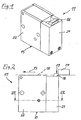
- Figur 1
- ein erstes Ausführungsbeispiel des erfindungsgemäßen Anschlagmoduls in perspektivischer Ansicht,
- Figur 2
- das Anschlagmodul von
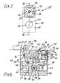
Figur 1 in Seitenansicht, - Figur 3
- das Anschlagmodul von
Figur 1 in Rückansicht, entgegen der Arbeitsbewegungsrichtung der Gegenstände, - Figur 4
- das Anschlagmodul von
Figur 3 im Längsschnitt entlang der Linie IV-IV ausFigur 3 , - Figur 5
- eine Rückansicht auf das Anschlagmodul von
Figur 1 , wobei sich das Anschlagglied im eingefahrenen Zustand befindet, - Figur 6
- das Anschlagmodul von
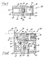
Figur 5 im Längsschnitt entlang der Linie VI-VI ausFigur 5 , - Figur 7
- das Anschlagmodul von
Figur 2 im Schnitt entlang der Linie VII-VII ausFigur 2 , - Figur 8
- ein zweites Ausführungsbeispiel des erfindungsgemäßen Anschlagmoduls im Längsschnitt,
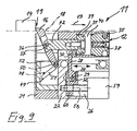
- Figur 9
- ein drittes Ausführungsbeispiel des erfindungsgemäßen Anschlagmoduls im Längsschnitt und
- Figuren 10A bis 10C
- eine schematische Darstellung des erfindungsgemäßen Anschlagmoduls im Einsatz an einer automatischen Fördereinrichtung, wobei in drei aufeinanderfolgenden Schritten A bis C die Freigabe eines angeschlagenen Gegenstandes durch Absenken des Anschlagglieds dargestellt ist.
- FIG. 1
- a first embodiment of the stop module according to the invention in a perspective view,
- FIG. 2
- the stop module of
FIG. 1 in side view, - FIG. 3
- the stop module of
FIG. 1 in rear view, contrary to the working direction of movement of the objects, - FIG. 4
- the stop module of
FIG. 3 in longitudinal section along the line IV-IVFIG. 3 . - FIG. 5
- a rear view of the stop module of
FIG. 1 , wherein the stop member is in the retracted state, - FIG. 6
- the stop module of
FIG. 5 in longitudinal section along the line VI-VIFIG. 5 . - FIG. 7
- the stop module of
FIG. 2 in section along the line VII-VIIFIG. 2 . - FIG. 8
- a second embodiment of the stop module according to the invention in longitudinal section,
- FIG. 9
- a third embodiment of the stop module according to the invention in longitudinal section and
- FIGS. 10A to 10C
- a schematic representation of the stop module according to the invention in use on an automatic conveyor, wherein in three successive steps A to C, the release of a damaged object by lowering the stop member is shown.
Die
Das Anschlagmodul 11 wird vorzugsweise in automatischen Bearbeitungs- und Fördereinrichtungen 70 eingesetzt, um sich in einer Bewegungsebene 18 in einer Arbeitsbewegungsrichtung 13 bewegende Gegenstände 14, beispielsweise Werkstücke oder dergleichen, zu vereinzeln. Nach der Vereinzelung können die Gegenstände 14 dann individuell behandelt, beispielsweise bearbeitet, umgeleitet usw. werden.The
Das Anschlagmodul 11 besitzt eine beispielsweise quaderförmig ausgebildete Grundeinheit 15, an dem ein Anschlagglied 16 angeordnet ist, das mittels eines Stellglieds 17 aus der Bewegungsebene 18 der Gegenstände 14 heraus und in diese zurück bewegbar ist. Ferner ist noch die bereits erwähnte Dämpfungseinrichtung 12 vorgesehen, mittels der das Anschlagglied 16 von einer in Arbeitsbewegungsrichtung 13 vor einer Anschlagstellung 20 liegenden Voranschlagstellung 19 bis zur Anschlagstellung 20 gedämpft bewegbar ist.The
Es ist möglich, dass die Grundeinheit 15 aus einem Anschlaggliedträger 21, in dem das Anschlagglied 16 in nachfolgend noch näher beschriebener Weise untergebracht ist, und einem separat vom Anschlaggliedträger 21 ausgebildeten Stellgliedträger 22 besteht. Prinzipiell ist jedoch auch eine einteilig aufgebaute Grundeinheit 15 denkbar.It is possible that the
Wie insbesondere in
Eine weitere Verringerung der Bauhöhe und sogar der gesamten Baugröße des Anschlagmoduls 11 kann durch die Verwendung relativ klein dimensionierter Stellglieder 17 in Kombination mit Umsetzmitteln in Form von Kraftübersetzungsmitteln erfolgen, so dass auch eine vom Stellglied 17 erzeugte relativ geringe Antriebskraft zur Bewegung des Antriebsglieds ausreicht, da diese über die Kraftübersetzung in eine höhere Kraft übersetzt wird.A further reduction in the overall height and even the overall size of the
Als Kraftübersetzungsmittel ist eine Hebelübersetzung vorgesehen, mit einer Hebeleinrichtung 27, die zwischen dem Anker des Elektromagneten 23 und dem Anschlagglied 16 ausgebildet ist. Die Hebeleinrichtung 27 besitzt einen ersten Hebel 28, der einerseits um eine erste Schwenkachse 29 schwenkbar am Anker und andererseits um eine zweite Schwenkachse 30 schwenkbar mit einem zweiten Hebel 31 verbunden ist.As a force translating means a lever transmission is provided, with a
Wie insbesondere in
Der zweite Hebel 31 wird von einem Dämpfungszylinder 38 der Dämpfungseinrichtung 12 gebildet. Dieser besitzt einen Zylinderraum 40, in dem ein Dämpfungskolben 39 verschiebbar geführt und mittels einer Kolbendichtungseinrichtung 41 gegen die Wandung des Zylinderraums 40 abgedichtet ist. Der Dämpfungskolben 39 ist mit einer Kolbenstange 42 über Befestigungsmittel, beispielsweise mittels einer Schraubverbindung 43, verbunden. Es ist selbstverständlich auch möglich, eine einstückige Verbindung zwischen Dämpfungskolben 39 und Kolbenstange 42 vorzusehen.The second lever 31 is formed by a damping
Am kolbenfernen Ende ist die Kolbenstange 42 wie erwähnt schwenkbar mit dem Anschlagglied 16 verbunden. Sie stellt somit das Stellelement für das Anschlagglied 16 dar. Zur Außenseite der Grundeinheit 15 hin ist der Zylinderraum 40 mit einem Deckel 44 verschlossen. Im Deckel 44 befindet sich eine Drosseleinrichtung 45, die einen Strömungswiderstand für die bei der Kolbenbewegung über einen nicht dargestellten Kanal ausströmende Luft bildet. Zur Feinjustierung der Dämpfungswirkung sind ferner Einstellmittel 46, beispielsweise eine in einem Deckelkanal 47 beweglich geführte Einstellschraube vorgesehen, mit der sich der Ausströmquerschnitt für die ausströmende Luft wahlweise verengen oder erweitern lässt, wodurch dann wiederum der Drosseleffekt erhöht oder vermindert wird, wobei letzterer wiederum die Dämpfungswirkung bestimmt. Wie insbesondere in den
Das Anschlagglied 16 ist wie erwähnt an einer zweiten Stelle 36 schwenkbar mit der Kolbenstange 42 verbunden. Zusätzlich hierzu ist eine Führungseinrichtung 48 vorgesehen, mit wenigstens einer Führungsbahn 49, auf der das Anschlagsglied 16 an einer ersten Stelle 50 zwischen der Anschlagstellung 16 und der Freigabestellung 25 zwangsgeführt ist.As mentioned, the
Wie insbesondere in
Wie in den
Gleichzeitig läuft der Führungsbolzen 52 im Führungsbereich 54 der Führungsnuten 51 schräg nach unten entgegen der Arbeitsbewegungsrichtung 13. Durch diesen Verlauf der jeweiligen Führungsbereiche 54 wird erreicht, dass bereits beim Absenken des Anschlagglieds die Kolbenstange 42 wieder aus dem Dämpfungszylinder 38 herausgezogen wird. Das untere Ende der jeweiligen Führungsbereiche 54 bildet schließlich die Freigabestellung 25. In der Freigabestellung 25 ist das Anschlagglied vollständig unterhalb der Bewegungsebene 18 angeordnet, so dass ein angeschlagener Gegenstand 14 über das Anschlagmodul 11 hinaus weitertransportiert werden kann. Beim anschließenden Hochfahren des Anschlagglieds, um einen nachfolgenden Gegenstand 14 zu stoppen bzw. zu vereinzeln, bleibt die Kolbenstange 42 in ihrer ausgestellten Position, so dass das Anschlagglied automatisch wieder in die in
Claims (9)
- Stop module, in particular for automatic machining and conveyor devices, with a stop element (16) arranged on a base unit (15) for objects (14) moving in a movement plane (18) in a current working movement direction (13), which module can be moved by means of an actuator (17) between a stop position (20) in the movement plane (18) and a release position (25) lying below the movement plane (18), wherein a guide device (48) is provided, with at least one guide path (49) on which the stop element (16) is force guided at a first point (50) between the stop position (20) and the release position (25), wherein the stop element (16) is connected swivelable with an actuator at a second point (36) remote from the first point (50) such that on a lowering movement of the stop element (16) from the stop position (20) into the release position (25), a swivelling of the stop element (16) takes place in the working movement direction (13), wherein the actuator (17) is coupled with the stop element (16) via force translation means in the form of a lever device (27), characterised in that a drive force generated by the actuator (17) can be translated into a greater force that can be tapped at the stop element (16), wherein the lever device (27) has a first lever (28) which is firstly mounted articulated on the actuator (17) and linearly displaceable and secondly is mounted articulated on a second lever (31), wherein the latter firstly can be swivelled about a stationary swivel axis (35) formed on the base unit (15) and secondly is mounted articulated on the stop element (16).
- Stop module according to Claim 1, characterised in that the guide path (49) runs at least partly obliquely to the movement plane (18).
- Stop module according to Claim 1 or 2, characterised in that the stop element (16) at its upper end has a stop contour which on movement of the stop element (16) between the stop position (20) and release position (25) describes a curved path (75).
- Stop module according to any one of the preceding claims, characterised in that the guide device (48) has a link guide with at least one guide link formed in the base unit (15) in which is force-guided at least one guide element arranged on the stop element (16).
- Stop module according to any one of the preceding claims, characterised by a damping device (12) connected to the stop element (16) for damped movement of the stop element from a pre-stop position (19) lying in front of the stop position (20) in the working movement direction (13) up to the stop position (20).
- Stop module according to any one of the preceding claims, characterised in that the second lever is formed by a damping cylinder (38) of the damping device (12).
- Stop module according to any one of the preceding claims, characterised in that the actuator (17) has a drive element (24) for generating a linear drive movement directed parallel to the movement plane (18), which drive movement can be converted via conversion means into an upward or downward movement taking place between the stop position (20) and the release position (25) of the stop element.
- Stop module according to Claim 7, characterised in that the drive element (24) is arranged linearly displaceable in a drive holder (26) formed in the base unit (15) parallel to the movement plane (18).
- Stop module according to Claim 8, characterised in that the actuator (17) is arranged in the drive holder (26) with its long side aligned substantially parallel to the movement plane (18).
Priority Applications (6)
| Application Number | Priority Date | Filing Date | Title |
|---|---|---|---|
| EP06400031A EP1902982B1 (en) | 2006-09-25 | 2006-09-25 | Stop module |
| AT06400031T ATE414662T1 (en) | 2006-09-25 | 2006-09-25 | STOP MODULE |
| DE502006002135T DE502006002135D1 (en) | 2006-09-25 | 2006-09-25 | stop module |
| KR1020070096564A KR100996222B1 (en) | 2006-09-25 | 2007-09-21 | An abutment module |
| US11/861,040 US7513355B2 (en) | 2006-09-25 | 2007-09-25 | Abutment module |
| CN2007101612236A CN101152929B (en) | 2006-09-25 | 2007-09-25 | Stop module |
Applications Claiming Priority (1)
| Application Number | Priority Date | Filing Date | Title |
|---|---|---|---|
| EP06400031A EP1902982B1 (en) | 2006-09-25 | 2006-09-25 | Stop module |
Publications (2)
| Publication Number | Publication Date |
|---|---|
| EP1902982A1 EP1902982A1 (en) | 2008-03-26 |
| EP1902982B1 true EP1902982B1 (en) | 2008-11-19 |
Family
ID=37708168
Family Applications (1)
| Application Number | Title | Priority Date | Filing Date |
|---|---|---|---|
| EP06400031A Active EP1902982B1 (en) | 2006-09-25 | 2006-09-25 | Stop module |
Country Status (6)
| Country | Link |
|---|---|
| US (1) | US7513355B2 (en) |
| EP (1) | EP1902982B1 (en) |
| KR (1) | KR100996222B1 (en) |
| CN (1) | CN101152929B (en) |
| AT (1) | ATE414662T1 (en) |
| DE (1) | DE502006002135D1 (en) |
Cited By (1)
| Publication number | Priority date | Publication date | Assignee | Title |
|---|---|---|---|---|
| DE102016219966A1 (en) * | 2016-10-13 | 2018-04-19 | Asutec Gmbh | stop module |
Families Citing this family (16)
| Publication number | Priority date | Publication date | Assignee | Title |
|---|---|---|---|---|
| DE102007062076A1 (en) * | 2007-12-21 | 2009-06-25 | Robert Bosch Gmbh | Stop module, in particular for automated processing and conveying devices |
| DE102010056035A1 (en) | 2010-12-15 | 2012-06-21 | Wörner Automatisierungstechnik GmbH | Workpiece stop module used in e.g. production plant for packing and labeling food products, has stopper and actuator which are coupled over lever mechanism such that stopper is moved on arc-shaped path in secondary direction |
| DE102010056036A1 (en) | 2010-12-15 | 2012-06-21 | Wörner Automatisierungstechnik GmbH | Stop module for position-accurate holding of workpiece in clean room in field of e.g. food industry, has cylinder filled with fluid whose viscosity is variably adjustable, and brake element including actuator to change viscosity of fluid |
| JP5698345B2 (en) * | 2011-03-23 | 2015-04-08 | 平田機工株式会社 | Stop device and stop release method |
| WO2012127530A1 (en) * | 2011-03-23 | 2012-09-27 | 平田機工株式会社 | Stopping device and stopping release method |
| CN102416577A (en) * | 2011-12-19 | 2012-04-18 | 贵州航天控制技术有限公司 | Anti-collision positioning stop mechanism |
| CN104203776B (en) * | 2012-03-27 | 2016-12-21 | 平田机工株式会社 | Arresting stop and temporarily cease method |
| DE102012103820B3 (en) * | 2012-05-02 | 2013-08-08 | Wörner Automatisierungstechnik GmbH | Stop module for position-precise stopping of e.g. workpiece in system for packing and labeling of food product, has lever device formed such that damping device is reset from end position into initial position during retraction movement |
| DE102013015525B4 (en) * | 2013-09-18 | 2019-10-24 | Asutec Gmbh | stop module |
| JP6276052B2 (en) * | 2014-02-10 | 2018-02-07 | 平田機工株式会社 | Stop device and auxiliary stop unit |
| DE102014110822B4 (en) | 2014-07-30 | 2016-10-27 | Wörner Automatisierungstechnik GmbH | Stop module for positionally accurate stopping of an object |
| DE102017104151B3 (en) * | 2017-02-28 | 2018-03-15 | Wörner Automatisierungstechnik GmbH | Stop module for positionally accurate stopping of an object |
| WO2018222887A1 (en) * | 2017-06-01 | 2018-12-06 | Usnr, Llc. | Lapper assembly |
| MX2020002722A (en) * | 2017-09-13 | 2020-11-06 | Flexlink Ab | Brake device for a conveyor system. |
| DE102018102172A1 (en) | 2018-01-31 | 2019-08-01 | Eto Magnetic Gmbh | Electromagnetic actuator with fastening means |
| DE102020106906B4 (en) | 2020-03-13 | 2021-10-28 | FAB Fördertechnik und Anlagenbau GmbH | Stopper device for a conveyor for conveying piece goods, for example for a roller conveyor or a belt conveyor |
Family Cites Families (13)
| Publication number | Priority date | Publication date | Assignee | Title |
|---|---|---|---|---|
| DE3003674C2 (en) * | 1980-02-01 | 1986-10-30 | Seitz Enzinger Noll Maschinenbau Ag, 6800 Mannheim | Device for stopping or turning bottle crates |
| JPS58188229A (en) * | 1982-04-26 | 1983-11-02 | Mazda Motor Corp | Stopping device at fixed position of conveying machine |
| DE9015950U1 (en) | 1990-11-07 | 1991-02-14 | Woerner, Helmut, 7306 Denkendorf, De | |
| JPH0497731U (en) * | 1991-01-22 | 1992-08-24 | ||
| US5168976A (en) * | 1992-02-14 | 1992-12-08 | Newcor, Inc. | Cushioned stop for powered conveyor |
| US5211276A (en) * | 1992-06-23 | 1993-05-18 | Tekno Inc. | Stop for conveyor |
| DE19543797A1 (en) * | 1995-11-24 | 1997-05-28 | Grob Gmbh & Co Kg | Pallet driving and controlling method on conveyor |
| US6119843A (en) | 1999-02-03 | 2000-09-19 | Robinson; Brian Owen | Retractable stop assembly |
| US6112877A (en) * | 1999-03-22 | 2000-09-05 | Dallas A. C. Horn & Co. | Decelerator for large conveyors |
| US6763930B2 (en) * | 2002-03-14 | 2004-07-20 | Rapistan Systems Advertising Corp. | Accumulation conveyor assembly |
| FR2856998A1 (en) * | 2003-05-19 | 2005-01-07 | Robotiques 3 Dimensions | Part stopping device, has vertical arm articulated about axis to co operate with activating unit jointed to central body for retracting stopper under moving plane by using kinetic energy of part |
| DE20315815U1 (en) * | 2003-10-10 | 2005-02-17 | Grob-Werke Burkhart Grob E.K. | Device for stopping transported goods |
| EP1746053B1 (en) * | 2005-07-19 | 2007-10-10 | Helmut Wörner | Stop and damper module |
-
2006
- 2006-09-25 DE DE502006002135T patent/DE502006002135D1/en active Active
- 2006-09-25 EP EP06400031A patent/EP1902982B1/en active Active
- 2006-09-25 AT AT06400031T patent/ATE414662T1/en active
-
2007
- 2007-09-21 KR KR1020070096564A patent/KR100996222B1/en active IP Right Grant
- 2007-09-25 US US11/861,040 patent/US7513355B2/en active Active
- 2007-09-25 CN CN2007101612236A patent/CN101152929B/en active Active
Cited By (2)
| Publication number | Priority date | Publication date | Assignee | Title |
|---|---|---|---|---|
| DE102016219966A1 (en) * | 2016-10-13 | 2018-04-19 | Asutec Gmbh | stop module |
| DE102016219966B4 (en) | 2016-10-13 | 2019-12-19 | Asutec Gmbh | stop module |
Also Published As
| Publication number | Publication date |
|---|---|
| KR100996222B1 (en) | 2010-11-24 |
| CN101152929A (en) | 2008-04-02 |
| US7513355B2 (en) | 2009-04-07 |
| KR20080027744A (en) | 2008-03-28 |
| ATE414662T1 (en) | 2008-12-15 |
| DE502006002135D1 (en) | 2009-01-02 |
| CN101152929B (en) | 2012-01-11 |
| EP1902982A1 (en) | 2008-03-26 |
| US20080073180A1 (en) | 2008-03-27 |
Similar Documents
| Publication | Publication Date | Title |
|---|---|---|
| EP1902982B1 (en) | Stop module | |
| EP1902981B1 (en) | Stop module | |
| EP1967472B1 (en) | Impact and damping module | |
| EP1674197B1 (en) | Feeding device for plateshaped workpieces | |
| EP2465637B1 (en) | Workpiece holder device for fixing a board-shaped workpiece, in particular a metal sheet to a workpiece movement unit of a machine tool | |
| AT514930B1 (en) | Backgauge unit for bending machine | |
| DE19543797A1 (en) | Pallet driving and controlling method on conveyor | |
| EP1746054B1 (en) | Stop module driven by electrical motor | |
| EP0481275A1 (en) | Machine tool with tool changing device | |
| EP1522383B1 (en) | Device for stopping goods | |
| EP3731997A1 (en) | Hydraulic tool for a pulling and/or pressing device | |
| EP3239567A1 (en) | Gate valve with curved guideway | |
| DE102006028493A1 (en) | stopping device | |
| DE60217851T2 (en) | THREAD TERMINAL FOR A WEAVING MACHINE AND WEB MACHINE WITH SUCH A THREAD TERMINAL | |
| DE3528337A1 (en) | Clamping device | |
| DE1483579B1 (en) | Device for venting molds on die casting machines | |
| DE102014005657A1 (en) | stop module | |
| DE3329942C1 (en) | Clamping device in particular for workpieces to be machined | |
| EP0107763B1 (en) | Vice, in particular a machine tool vice | |
| EP1916065B1 (en) | Support head | |
| DE10213850C1 (en) | Device for ejecting workpieces from single- or multi-stage presses comprises an ejector pin pivoting on a support part which travels on a pressing frame perpendicularly to the longitudinal axis of the pin | |
| WO2001087512A1 (en) | Transfer device and method for controlling a transfer device | |
| EP0873205B1 (en) | Bending machine | |
| DE10007255A1 (en) | Work piece ejector for single/multistage press e.g. screws, rivets, etc. has ejector peg charged by pivoted ejector lever | |
| EP0297470A2 (en) | Pneumatically actuated stop for advanced workpieces |
Legal Events
| Date | Code | Title | Description |
|---|---|---|---|
| PUAI | Public reference made under article 153(3) epc to a published international application that has entered the european phase |
Free format text: ORIGINAL CODE: 0009012 |
|
| 17P | Request for examination filed |
Effective date: 20070419 |
|
| AK | Designated contracting states |
Kind code of ref document: A1 Designated state(s): AT BE BG CH CY CZ DE DK EE ES FI FR GB GR HU IE IS IT LI LT LU LV MC NL PL PT RO SE SI SK TR |
|
| AX | Request for extension of the european patent |
Extension state: AL BA HR MK YU |
|
| GRAP | Despatch of communication of intention to grant a patent |
Free format text: ORIGINAL CODE: EPIDOSNIGR1 |
|
| GRAS | Grant fee paid |
Free format text: ORIGINAL CODE: EPIDOSNIGR3 |
|
| GRAA | (expected) grant |
Free format text: ORIGINAL CODE: 0009210 |
|
| AK | Designated contracting states |
Kind code of ref document: B1 Designated state(s): AT BE BG CH CY CZ DE DK EE ES FI FR GB GR HU IE IS IT LI LT LU LV MC NL PL PT RO SE SI SK TR |
|
| REG | Reference to a national code |
Ref country code: GB Ref legal event code: FG4D Free format text: NOT ENGLISH |
|
| REG | Reference to a national code |
Ref country code: CH Ref legal event code: EP Ref country code: CH Ref legal event code: NV Representative=s name: TROESCH SCHEIDEGGER WERNER AG |
|
| AKX | Designation fees paid |
Designated state(s): AT BE BG CH CY CZ DE DK EE ES FI FR GB GR HU IE IS IT LI LT LU LV MC NL PL PT RO SE SI SK TR |
|
| REG | Reference to a national code |
Ref country code: IE Ref legal event code: FG4D Free format text: LANGUAGE OF EP DOCUMENT: GERMAN |
|
| REF | Corresponds to: |
Ref document number: 502006002135 Country of ref document: DE Date of ref document: 20090102 Kind code of ref document: P |
|
| LTIE | Lt: invalidation of european patent or patent extension |
Effective date: 20081119 |
|
| PG25 | Lapsed in a contracting state [announced via postgrant information from national office to epo] |
Ref country code: LT Free format text: LAPSE BECAUSE OF FAILURE TO SUBMIT A TRANSLATION OF THE DESCRIPTION OR TO PAY THE FEE WITHIN THE PRESCRIBED TIME-LIMIT Effective date: 20081119 Ref country code: ES Free format text: LAPSE BECAUSE OF FAILURE TO SUBMIT A TRANSLATION OF THE DESCRIPTION OR TO PAY THE FEE WITHIN THE PRESCRIBED TIME-LIMIT Effective date: 20090301 |
|
| NLV1 | Nl: lapsed or annulled due to failure to fulfill the requirements of art. 29p and 29m of the patents act | ||
| PG25 | Lapsed in a contracting state [announced via postgrant information from national office to epo] |
Ref country code: PL Free format text: LAPSE BECAUSE OF FAILURE TO SUBMIT A TRANSLATION OF THE DESCRIPTION OR TO PAY THE FEE WITHIN THE PRESCRIBED TIME-LIMIT Effective date: 20081119 Ref country code: NL Free format text: LAPSE BECAUSE OF FAILURE TO SUBMIT A TRANSLATION OF THE DESCRIPTION OR TO PAY THE FEE WITHIN THE PRESCRIBED TIME-LIMIT Effective date: 20081119 Ref country code: IS Free format text: LAPSE BECAUSE OF FAILURE TO SUBMIT A TRANSLATION OF THE DESCRIPTION OR TO PAY THE FEE WITHIN THE PRESCRIBED TIME-LIMIT Effective date: 20090319 Ref country code: SI Free format text: LAPSE BECAUSE OF FAILURE TO SUBMIT A TRANSLATION OF THE DESCRIPTION OR TO PAY THE FEE WITHIN THE PRESCRIBED TIME-LIMIT Effective date: 20081119 Ref country code: LV Free format text: LAPSE BECAUSE OF FAILURE TO SUBMIT A TRANSLATION OF THE DESCRIPTION OR TO PAY THE FEE WITHIN THE PRESCRIBED TIME-LIMIT Effective date: 20081119 Ref country code: FI Free format text: LAPSE BECAUSE OF FAILURE TO SUBMIT A TRANSLATION OF THE DESCRIPTION OR TO PAY THE FEE WITHIN THE PRESCRIBED TIME-LIMIT Effective date: 20081119 |
|
| REG | Reference to a national code |
Ref country code: IE Ref legal event code: FD4D |
|
| PG25 | Lapsed in a contracting state [announced via postgrant information from national office to epo] |
Ref country code: EE Free format text: LAPSE BECAUSE OF FAILURE TO SUBMIT A TRANSLATION OF THE DESCRIPTION OR TO PAY THE FEE WITHIN THE PRESCRIBED TIME-LIMIT Effective date: 20081119 Ref country code: DK Free format text: LAPSE BECAUSE OF FAILURE TO SUBMIT A TRANSLATION OF THE DESCRIPTION OR TO PAY THE FEE WITHIN THE PRESCRIBED TIME-LIMIT Effective date: 20081119 Ref country code: BG Free format text: LAPSE BECAUSE OF FAILURE TO SUBMIT A TRANSLATION OF THE DESCRIPTION OR TO PAY THE FEE WITHIN THE PRESCRIBED TIME-LIMIT Effective date: 20090219 Ref country code: IE Free format text: LAPSE BECAUSE OF FAILURE TO SUBMIT A TRANSLATION OF THE DESCRIPTION OR TO PAY THE FEE WITHIN THE PRESCRIBED TIME-LIMIT Effective date: 20081119 Ref country code: RO Free format text: LAPSE BECAUSE OF FAILURE TO SUBMIT A TRANSLATION OF THE DESCRIPTION OR TO PAY THE FEE WITHIN THE PRESCRIBED TIME-LIMIT Effective date: 20081119 |
|
| PG25 | Lapsed in a contracting state [announced via postgrant information from national office to epo] |
Ref country code: PT Free format text: LAPSE BECAUSE OF FAILURE TO SUBMIT A TRANSLATION OF THE DESCRIPTION OR TO PAY THE FEE WITHIN THE PRESCRIBED TIME-LIMIT Effective date: 20090420 Ref country code: CZ Free format text: LAPSE BECAUSE OF FAILURE TO SUBMIT A TRANSLATION OF THE DESCRIPTION OR TO PAY THE FEE WITHIN THE PRESCRIBED TIME-LIMIT Effective date: 20081119 Ref country code: SE Free format text: LAPSE BECAUSE OF FAILURE TO SUBMIT A TRANSLATION OF THE DESCRIPTION OR TO PAY THE FEE WITHIN THE PRESCRIBED TIME-LIMIT Effective date: 20090219 |
|
| PLBE | No opposition filed within time limit |
Free format text: ORIGINAL CODE: 0009261 |
|
| STAA | Information on the status of an ep patent application or granted ep patent |
Free format text: STATUS: NO OPPOSITION FILED WITHIN TIME LIMIT |
|
| PG25 | Lapsed in a contracting state [announced via postgrant information from national office to epo] |
Ref country code: SK Free format text: LAPSE BECAUSE OF FAILURE TO SUBMIT A TRANSLATION OF THE DESCRIPTION OR TO PAY THE FEE WITHIN THE PRESCRIBED TIME-LIMIT Effective date: 20081119 |
|
| 26N | No opposition filed |
Effective date: 20090820 |
|
| BERE | Be: lapsed |
Owner name: UNTERHUBER, SEBASTIAN Effective date: 20090930 Owner name: WORNER, HELMUT Effective date: 20090930 |
|
| PG25 | Lapsed in a contracting state [announced via postgrant information from national office to epo] |
Ref country code: MC Free format text: LAPSE BECAUSE OF NON-PAYMENT OF DUE FEES Effective date: 20090930 |
|
| REG | Reference to a national code |
Ref country code: FR Ref legal event code: ST Effective date: 20100531 |
|
| PG25 | Lapsed in a contracting state [announced via postgrant information from national office to epo] |
Ref country code: FR Free format text: LAPSE BECAUSE OF NON-PAYMENT OF DUE FEES Effective date: 20090930 |
|
| PG25 | Lapsed in a contracting state [announced via postgrant information from national office to epo] |
Ref country code: BE Free format text: LAPSE BECAUSE OF NON-PAYMENT OF DUE FEES Effective date: 20090930 |
|
| PG25 | Lapsed in a contracting state [announced via postgrant information from national office to epo] |
Ref country code: GR Free format text: LAPSE BECAUSE OF FAILURE TO SUBMIT A TRANSLATION OF THE DESCRIPTION OR TO PAY THE FEE WITHIN THE PRESCRIBED TIME-LIMIT Effective date: 20090220 |
|
| REG | Reference to a national code |
Ref country code: CH Ref legal event code: PUE Owner name: SEBASTIAN UNTERHUBER Free format text: UNTERHUBER, SEBASTIAN#RILKEWEG 4#73257 KOENGEN (DE) $ WOERNER, HELMUT#JOHANN-SEBASTIAN-BACH-STRASSE 3#73770 DENKENDORF (DE) -TRANSFER TO- SEBASTIAN UNTERHUBER#RILKEWEG 4#73257 KOEGEN (DE) |
|
| REG | Reference to a national code |
Ref country code: CH Ref legal event code: NV Representative=s name: TROESCH SCHEIDEGGER WERNER AG Ref country code: CH Ref legal event code: PK |
|
| PG25 | Lapsed in a contracting state [announced via postgrant information from national office to epo] |
Ref country code: IT Free format text: LAPSE BECAUSE OF FAILURE TO SUBMIT A TRANSLATION OF THE DESCRIPTION OR TO PAY THE FEE WITHIN THE PRESCRIBED TIME-LIMIT Effective date: 20081119 |
|
| REG | Reference to a national code |
Ref country code: GB Ref legal event code: 732E Free format text: REGISTERED BETWEEN 20110310 AND 20110316 |
|
| PG25 | Lapsed in a contracting state [announced via postgrant information from national office to epo] |
Ref country code: LU Free format text: LAPSE BECAUSE OF NON-PAYMENT OF DUE FEES Effective date: 20090925 |
|
| REG | Reference to a national code |
Ref country code: DE Ref legal event code: R081 Ref document number: 502006002135 Country of ref document: DE Owner name: UNTERHUBER, SEBASTIAN, DE Free format text: FORMER OWNER: HELMUT WOERNER,SEBASTIAN UNTERHUBER, , DE Effective date: 20110314 Ref country code: DE Ref legal event code: R081 Ref document number: 502006002135 Country of ref document: DE Owner name: UNTERHUBER, SEBASTIAN, DE Free format text: FORMER OWNERS: WOERNER, HELMUT, 73770 DENKENDORF, DE; UNTERHUBER, SEBASTIAN, 73257 KOENGEN, DE Effective date: 20110314 |
|
| PG25 | Lapsed in a contracting state [announced via postgrant information from national office to epo] |
Ref country code: HU Free format text: LAPSE BECAUSE OF FAILURE TO SUBMIT A TRANSLATION OF THE DESCRIPTION OR TO PAY THE FEE WITHIN THE PRESCRIBED TIME-LIMIT Effective date: 20090520 |
|
| PG25 | Lapsed in a contracting state [announced via postgrant information from national office to epo] |
Ref country code: TR Free format text: LAPSE BECAUSE OF FAILURE TO SUBMIT A TRANSLATION OF THE DESCRIPTION OR TO PAY THE FEE WITHIN THE PRESCRIBED TIME-LIMIT Effective date: 20081119 |
|
| PG25 | Lapsed in a contracting state [announced via postgrant information from national office to epo] |
Ref country code: CY Free format text: LAPSE BECAUSE OF FAILURE TO SUBMIT A TRANSLATION OF THE DESCRIPTION OR TO PAY THE FEE WITHIN THE PRESCRIBED TIME-LIMIT Effective date: 20081119 |
|
| PGFP | Annual fee paid to national office [announced via postgrant information from national office to epo] |
Ref country code: CH Payment date: 20110928 Year of fee payment: 6 |
|
| PGFP | Annual fee paid to national office [announced via postgrant information from national office to epo] |
Ref country code: AT Payment date: 20110905 Year of fee payment: 6 Ref country code: GB Payment date: 20110907 Year of fee payment: 6 |
|
| REG | Reference to a national code |
Ref country code: CH Ref legal event code: PL |
|
| REG | Reference to a national code |
Ref country code: AT Ref legal event code: MM01 Ref document number: 414662 Country of ref document: AT Kind code of ref document: T Effective date: 20120925 |
|
| GBPC | Gb: european patent ceased through non-payment of renewal fee |
Effective date: 20120925 |
|
| PG25 | Lapsed in a contracting state [announced via postgrant information from national office to epo] |
Ref country code: AT Free format text: LAPSE BECAUSE OF NON-PAYMENT OF DUE FEES Effective date: 20120925 Ref country code: LI Free format text: LAPSE BECAUSE OF NON-PAYMENT OF DUE FEES Effective date: 20120930 Ref country code: GB Free format text: LAPSE BECAUSE OF NON-PAYMENT OF DUE FEES Effective date: 20120925 Ref country code: CH Free format text: LAPSE BECAUSE OF NON-PAYMENT OF DUE FEES Effective date: 20120930 |
|
| PGFP | Annual fee paid to national office [announced via postgrant information from national office to epo] |
Ref country code: DE Payment date: 20230823 Year of fee payment: 18 |