EP1902452B1 - Verfahren zur herstellung einer magnetischen schichtschaltung - Google Patents
Verfahren zur herstellung einer magnetischen schichtschaltung Download PDFInfo
- Publication number
- EP1902452B1 EP1902452B1 EP06778850A EP06778850A EP1902452B1 EP 1902452 B1 EP1902452 B1 EP 1902452B1 EP 06778850 A EP06778850 A EP 06778850A EP 06778850 A EP06778850 A EP 06778850A EP 1902452 B1 EP1902452 B1 EP 1902452B1
- Authority
- EP
- European Patent Office
- Prior art keywords
- stack
- sheets
- mpa
- adhesive
- magnetic circuit
- Prior art date
- Legal status (The legal status is an assumption and is not a legal conclusion. Google has not performed a legal analysis and makes no representation as to the accuracy of the status listed.)
- Active
Links
Images
Classifications
-
- H—ELECTRICITY
- H02—GENERATION; CONVERSION OR DISTRIBUTION OF ELECTRIC POWER
- H02K—DYNAMO-ELECTRIC MACHINES
- H02K15/00—Processes or apparatus specially adapted for manufacturing, assembling, maintaining or repairing of dynamo-electric machines
- H02K15/02—Processes or apparatus specially adapted for manufacturing, assembling, maintaining or repairing of dynamo-electric machines of stator or rotor bodies
-
- H—ELECTRICITY
- H01—ELECTRIC ELEMENTS
- H01F—MAGNETS; INDUCTANCES; TRANSFORMERS; SELECTION OF MATERIALS FOR THEIR MAGNETIC PROPERTIES
- H01F3/00—Cores, Yokes, or armatures
- H01F3/02—Cores, Yokes, or armatures made from sheets
-
- H—ELECTRICITY
- H01—ELECTRIC ELEMENTS
- H01F—MAGNETS; INDUCTANCES; TRANSFORMERS; SELECTION OF MATERIALS FOR THEIR MAGNETIC PROPERTIES
- H01F41/00—Apparatus or processes specially adapted for manufacturing or assembling magnets, inductances or transformers; Apparatus or processes specially adapted for manufacturing materials characterised by their magnetic properties
- H01F41/02—Apparatus or processes specially adapted for manufacturing or assembling magnets, inductances or transformers; Apparatus or processes specially adapted for manufacturing materials characterised by their magnetic properties for manufacturing cores, coils, or magnets
- H01F41/0206—Manufacturing of magnetic cores by mechanical means
- H01F41/0233—Manufacturing of magnetic circuits made from sheets
-
- H—ELECTRICITY
- H01—ELECTRIC ELEMENTS
- H01F—MAGNETS; INDUCTANCES; TRANSFORMERS; SELECTION OF MATERIALS FOR THEIR MAGNETIC PROPERTIES
- H01F27/00—Details of transformers or inductances, in general
- H01F27/34—Special means for preventing or reducing unwanted electric or magnetic effects, e.g. no-load losses, reactive currents, harmonics, oscillations, leakage fields
- H01F2027/348—Preventing eddy currents
Definitions
- the present invention relates to a method of manufacturing laminated magnetic circuits, and a magnetic circuit obtained by this method.
- a laminated magnetic circuit is generally formed of a stack of sheets, each having the shape of at least a portion of the section of the magnetic circuit to be obtained, sheets between which is interposed an insulating layer.
- This layer serves to limit or even eliminate eddy currents responsible for magnetic and thermal losses, the disadvantages of which are well known in the case of such magnetic circuits.
- a rotor or a stator generally comprises a stack of annular thin sheets of ferromagnetic material in which are formed slots for receiving the coil.
- the outer perimeter in the case of a rotor or the central passage of the stack in the case of a stator, in which the notches open, serves to respectively receive the stator or the rotor of the machine.
- a geometry defect may cause stator and rotor misalignments that can cause a decrease in performance (especially when starting an engine for example) and require thus an oversizing of the mechanical parts of the machine.
- the present invention is intended in particular to provide a method of manufacturing a laminated magnetic circuit for obtaining a stack having a cohesion and rigidity such that the subsequent machining does not cause any delamination and can be performed with great precision.
- the invention therefore relates to a method for manufacturing a laminated magnetic circuit according to claim 1, whether for stators and rotors of rotating machines (motors, alternators, generators, etc.), or for transformers, electro magnets and other similar apparatus, consisting of a stack of sheets of ferromagnetic material.
- this screen printing process offers a total control of the quantity and therefore the volume of glue deposited, thus making it possible to exclude any risk of overflow of excess glue.
- EDM does not affect the adhesive layers between the sheets, and thus allows both perfect insulation and perfect adhesion to be maintained. of these layers relative to each other.
- the machining EDM eliminates the risk of delamination incurred with conventional machining processes and reduce the number of manufacturing steps.
- said electroerosion is wired. In this way, one can achieve a high precision machining.
- the surfaces of said stack to be machined are covered with an electrically conductive resin.
- Such a resin makes it possible to electrically connect the plates of the magnetic circuit to each other, and thus to place them at the same electrical potential, which allows very easy implementation of electroerosion.
- a preferred embodiment of the method of the invention is applicable by way of example to the manufacture of a laminated magnetic circuit for a stator of a rotating machine such as an engine. electric.
- the invention is not limited to such stators, but applies to any laminated magnetic circuit, whether for stators and rotors of rotating machines (alternator motors, generators, etc.), or for transformers, electromagnets and other similar apparatus.
- the method consists first of all in the manufacture of sheets, for example by stamping, in a ferromagnetic sheet material of the Fe-Ni type, the sheets each having a general shape. circular ring.
- the sheets each having a general shape. circular ring.
- Their dimensions and the nature of the material of which they are made are naturally chosen according to the characteristics of the stator to be realized.
- the next step of the process consists in coating each sheet either on one face, or preferably on both sides, with an insulating adhesive layer.
- the coating is performed by screen printing through a screen.
- the apparatus comprises a screen 1 formed of a frame 2 on which is stretched a fabric 3.
- this fabric is made of taffeta with a mesh (diameter of the yarn and number of threads per unit length) chosen according to characteristics of the adhesive to be deposited and the deposit thickness thereof.
- the taffeta mesh fabric is preferably made of polyamide or polyester. It is also possible to use a twill mesh fabric.
- the fabric 3 is made impervious to glue in the areas outside of that corresponding to the shape of the sheet 4 on which the deposit must be made.
- the permeable zone of the fabric 3 is indicated by the arrow F (It should be noted that to simplify the figure 1 the entire surface of either the sieve 1 or the sheet 4) is not shown.
- the sheet 4 is kept pressed against the fabric 3, as shown in FIG. figure 1 .
- the screen printing apparatus also comprises a scraper device 5 known per se and whose scraper 6 extends over one of the dimensions of the fabric 3 and is movable along the other dimension thereof to the using a mechanism shown schematically at 7.
- the adhesive that can be used for the screen-printing coating of the sheets is a thermosetting structural glue of medium to high viscosity, the term "structural" signifying here that after fabrication of the magnetic circuit, the glue and the sheets form a perfectly one-piece assembly. a solid and rigid structure.
- the resin may be a polyurethane resin, an epoxy resin, or an acrylic resin.
- the viscosity of the adhesive is chosen in a range from 4000 to 400,000 mPa.s, preferably in a range from 75,000 to 100,000 mPa.s, a preferred value being 80,000 mPa.s.
- the coating thickness of the sheets 4 is chosen in a range from 1 to 100 ⁇ m, preferably from 5 to 10 ⁇ m, a preferred value being 8 ⁇ m.
- Loctite® 686 or Araldite® AW136 brand glues with type HV998 hardener have been used successfully for coating sheet 4.
- the glue or its components are degassed before being used in screen printing equipment to remove air and moisture.
- a first degassing may be carried out at 2 mbar, for example.
- the components are dosed, mixed and degassed again up to 20 mbar.
- Each sheet 4 is then placed under the screen printing screen 1 to be coated.
- the apparatus 5 performs several scraping passes to force the glue to pass through the fabric 3.
- the next step of the method according to the invention consists in stacking the sheets coated with adhesive as indicated above, in a tool adapted to be placed in a press, the number of sheets stacked in the tool being chosen according to the axial length. of the stator to obtain.
- the sheets are transferred immediately into the press tooling.
- Stacking compression parameters such as pressure, temperature and time are chosen in particular depending on the type of glue used and the dimensions of the stack. To limit the compressive forces, it is advantageous to give the sheets an overall shape that is as close as possible to the final shape, because these efforts must be even more important than the area of the stack on which are exerted the efforts are important.
- the parameters of the stacking polymerization operation such as temperature, pressure and time are chosen in accordance with the glue data sheet.
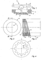
- a blank of a laminated magnetic circuit is obtained whose shape corresponds to that shown in FIG. Figures 2 and 3 .
- a stator corresponding to the example described, it is a tubular piece 8 of circular section and having a bore 9 also of circular section. It is formed of a succession of alternating layers formed of sheets 4 and layers of polymerized adhesive 10 constituting a rigid one-piece assembly whose precision in thickness and flatness depend both on the number of stacked sheets, on the thickness of the sheets, the thickness of the glue films as well as the pressing force.
- the blank thus obtained can then be subjected to machining operations to give it the shape and the nominal dimensions.
- these operations consist in subjecting the blank to wire EDM.
- This particular electroerosion process consists in producing capacitor-type electric discharges between a wire electrode and a workpiece.
- the electrode never comes into contact with the workpieces, and it is the discharges that generate micro plasmas that are locally several thousand degrees (about 10,000 ° C) that evaporate the metal materials.
- the surfaces to be machined of the blank are coated with an electrically conductive resin, for example a resin loaded with silver.
- an electrically conductive resin for example a resin loaded with silver.
- the conductive resin makes it possible to obtain equipotential surfaces for all the sheets 4, thus enabling the electroerosion wire to work.
- the method of the invention has many advantages.
- the screen printing step makes it possible to use glues of medium to high viscosity, which reduces the risks of localized lack of glue and the presence of gas bubbles on the surface of the sheets.
- This method also allows perfect control of the amount of adhesive deposited and therefore the coating thickness of each sheet of the stack.
- the control of the glue thickness and the pressing force makes it possible to accurately determine the final axial dimension of the stack after compression. It has been found that the iron / insulator ratio of the magnetic circuit can be better than 90%, a value of 97.5% being obtainable in some cases.
- the stack has a cohesion and rigidity such that the subsequent machining does not cause any delamination.
- This machining is not done on each sheet separately, it is possible to overcome the dimensional discrepancies both of the sheets themselves that the stack may occur if the sheets were machined individually.
- EDM allows stacking the required dimensions with very good accuracy.
- the cohesion and the mechanical rigidity of the magnetic circuit finally obtained also prevent any deformation of the magnetic circuit in the machine that is equipped, which makes it possible to reduce its dimensions, to prolong its life and to increase its performance. .
- the method of the invention can be applied for the manufacture of motors, generators, transformers and electromagnets and lightweight similar lightweight devices usable in particular in the field of space, aeronautics, automotive, railway etc.
- a plurality of 200 micron thick sheets are prepared by stamping them into ferromagnetic sheet material of the Fe-Ni type. Since the magnetic circuit to be obtained is intended to form the stator of an electric motor, the sheets have an annular shape whose outer diameter is slightly greater and whose internal diameter is slightly smaller than the corresponding nominal diameters that the finished circuit to be made. The leaves do not yet have the notches for receiving the stator winding. Their surface is equivalent to 17 500 mm 2 .
- Each of the sheets of sheet metal is then coated with a layer of adhesive with a thickness of 8 ⁇ m.
- the adhesive layer is deposited by screen printing using an apparatus similar to that shown in FIG. figure 1 .
- the screen printing screen comprises a taffeta cloth whose thread has a diameter of 30 ⁇ m with a yarn density of 200 threads per cm.
- the adhesive is an Araldite® AW136 resin mixed with an HV998 hardener.
- the screen printing operation is carried out at ambient temperature.
- Adhesive-coated sheets sufficient in number to constitute the entire stack of the future magnetic circuit, are deposited in a tool which is then put in press. This is actuated to compress the stack under a pressure of 13 MPa at a temperature of 120 ° for 5 minutes. On leaving the press, the adhesive is fully polymerized, the stack forming a perfectly monoblock unit.
- the cylindrical surfaces of the stack are then coated with an electrically conductive epoxy resin such as the resin of the Elecolit® 340 type.
- the stack thus coated is then machined by electroerosion, during which the inside and outside diameters of the stack are brought to their nominal values and the notches are formed inside the passage of the stack.
- the magnetic circuit obtained has an iron / insulator ratio of 97.5% and excellent resistance to delamination.
Landscapes
- Engineering & Computer Science (AREA)
- Power Engineering (AREA)
- Manufacturing & Machinery (AREA)
- Manufacture Of Motors, Generators (AREA)
- Manufacturing Cores, Coils, And Magnets (AREA)
- Thin Magnetic Films (AREA)
Claims (12)
- Verfahren zur Herstellung einer geschichteten MagnetSchaltung für Statoren und Rotoren von Drehmaschinen (Motoren, Wechselstromgeneratoren, Generatoren, usw.) oder für Transformatoren, Elektromagneten und andere derartige Geräte, bestehend aus einer Stapelung von Blechen (4) aus einem ferromagnetischen Material, darin bestehend:mindestens eine Fläche jedes der Bleche (4) mit einem Haftmittel zu überziehen,die überzogenen Bleche zu stapeln,den so erhaltenen Stapel durch Härtern des Haftmittels zu komprimieren, unddurch Elektroerosion den Blechstapel zu bearbeiten, bis die Nominalform und -abmessungen der endgültigen Magnetschaltung erhalten werden,dadurch gekennzeichnet, dass die Bleche (4) durch Serigraphie mit einer Schicht eines Haftmittels mit einer Viskosität zwischen 4000 mPa.s und 400 000 mPa.s und vorzugsweise zwischen 18 000 mPa.s und 150 000 mPa.s und einer gewählten Dicke zwischen 1 und 100 µm und vorzugsweise zwischen 5 und 10 µm überzogen werden.
- Herstellungsverfahren nach Anspruch 1, dadurch gekennzeichnet, dass das Serigraphieverfahren über ein Gewerbe (3) aus Taft oder Köper.
- Herstellungsverfahren nach Anspruch 2, dadurch gekennzeichnet, dass das Gewebe (3) einen Fadendurchmesser von 30 bis 250 µm und eine Fadendichte von 10 bis 220 Fäden pro cm aufweist.
- Herstellungsverfahren nach einem der Ansprüche 1 bis 3, dadurch gekennzeichnet, dass die Elektroerosion den Faden betrifft.
- Herstellungsverfahren nach einem der Ansprüche 1 bis 4, dadurch gekennzeichnet, dass vor dem Bearbeitungsverfahren durch Elektroerosion die Oberflächen des zu bearbeitenden Stapels mit einem elektrisch leitenden Harz überzogen werden.
- Herstellungsverfahren nach Anspruch 5, dadurch gekennzeichnet, dass das elektrisch leitende Harz ein Epoxyharz oder ein Acrylharz ist.
- Herstellungsverfahren nach einem der vorhergehenden Ansprüche, dadurch gekennzeichnet, dass das Haftmittel ein duroplastisches Harz, wie beispielsweise ein Polyurethanharz, ein Epoxyharz oder ein Acrylharz ist.
- Herstellungsverfahren nach einem der vorergehenden Ansprüche, dadurch gekennzeichnet, dass nach dem verfahren des Überziehens das Stapeln der überzogenen Bleche (4) erfolgt, indem sie übereinander angeordnet werden, so dass die fasern des ferromagnetischen Materials von einem Blech zum nächsten versetzt augerichtet sind und der Stapel die bestmögliche radiale Isotropie aufweist.
- Herstellungsverfahren nach einem der vorhergehenden Ansprüche, dadurch gekennzeichnet, dass während des Kompressionsverfahrens der Stapel einem Druck zwischen 1 MPa und 30 MPa und vorzugsweise zwischen 5 MPa und 15 MPa ausgesetzt wird.
- Herstellungsverfahren nach einem der Ansprüche 1 bis 9, dadurch gekennzeichnet, dass während des Kompressionsverfahrens der Stapel einer Temperatur zwischen 20 °C und 150 °C und vorzugsweise zwischen 50 °C und 100 °C ausgesetzt wird.
- Herstellungsverfahren nach einem der vorhergehenden Ansprüche, dadurch gekennzeichnet, dass während des Kompressionsverfahrens der Druck während einer Zeit zwischen 1 Minute und 60 Minuten und vorzugsweise zwischen 5 Minuten und 30 Minuten aufrechterhalten wird.
- Herstellungsverfahren nach einem der vorergehenden Ansprüche, dadurch gekennzeichnet, dass vor dem Vorgang des Überziehens die Bleche (4) derart ausgeführt werden, dass sie Gesamtabmessungen nahe jenen aufweisen, die sie in der endgültigen Magnetschaltung haben werden.
Applications Claiming Priority (2)
| Application Number | Priority Date | Filing Date | Title |
|---|---|---|---|
| FR0507311A FR2888390B1 (fr) | 2005-07-08 | 2005-07-08 | Procede de fabrication d'un circuit magnetique feuillete |
| PCT/FR2006/001680 WO2007006965A1 (fr) | 2005-07-08 | 2006-07-10 | Procede de fabrication d'un circuit magnetique feuillete |
Publications (2)
| Publication Number | Publication Date |
|---|---|
| EP1902452A1 EP1902452A1 (de) | 2008-03-26 |
| EP1902452B1 true EP1902452B1 (de) | 2011-08-10 |
Family
ID=36087791
Family Applications (1)
| Application Number | Title | Priority Date | Filing Date |
|---|---|---|---|
| EP06778850A Active EP1902452B1 (de) | 2005-07-08 | 2006-07-10 | Verfahren zur herstellung einer magnetischen schichtschaltung |
Country Status (5)
| Country | Link |
|---|---|
| EP (1) | EP1902452B1 (de) |
| AT (1) | ATE520135T1 (de) |
| ES (1) | ES2378047T3 (de) |
| FR (1) | FR2888390B1 (de) |
| WO (1) | WO2007006965A1 (de) |
Families Citing this family (4)
| Publication number | Priority date | Publication date | Assignee | Title |
|---|---|---|---|---|
| DE102012005795A1 (de) * | 2012-03-14 | 2013-09-19 | Kienle + Spiess Gmbh | Lamellenpaket und Verfahren zu seiner Herstellung |
| FR3042923B1 (fr) * | 2015-10-23 | 2017-12-29 | R Bourgeois | Paquet de toles fixees entre elles par collage, procede et installation de fabrication d'un tel paquet de toles |
| CA2962212C (en) | 2016-05-20 | 2024-05-14 | Skf Magnetic Mechatronics | Method of manufacturing a lamination stack for use in an electrical machine |
| CN116742910B (zh) * | 2023-07-10 | 2023-11-17 | 苏州首栎德技术有限公司 | 一种电机的定子片涂胶方法 |
Family Cites Families (8)
| Publication number | Priority date | Publication date | Assignee | Title |
|---|---|---|---|---|
| FR1432280A (fr) * | 1964-05-06 | 1966-03-18 | Oerlikon Maschf | Procédé et dispositif pour l'usinage de finition de pièces métalliques |
| DE2151960B2 (de) * | 1971-10-19 | 1976-03-11 | Lepper-Dominit Transformatoren Gmbh, 5340 Bad Honnef | Transformatorkern |
| JPS6158451A (ja) * | 1984-08-30 | 1986-03-25 | Toshiba Corp | 回転電機用非晶質金属コア−の製造方法 |
| GB2271219A (en) * | 1992-09-22 | 1994-04-06 | Simmonds Precision Engine Syst | Preventing interlayer shorting in a magnetic alloy laminate |
| FR2791484B1 (fr) * | 1999-03-24 | 2004-01-23 | Valeo Systemes Dessuyage | Procede de realisation d'un bobinage pour machine electrique tournante, et machine electrique tournante comportant un tel bobinage |
| EP1473377B1 (de) | 2002-01-16 | 2009-04-22 | Nakagawa Special Steel Co., Ltd. | Magnetisches grundmaterial, laminat aus magnetischem grundmaterial und herstellungsverfahren dafür |
| JP4081383B2 (ja) * | 2003-02-03 | 2008-04-23 | サカイオーベックス株式会社 | 繊維製品 |
| US7235910B2 (en) * | 2003-04-25 | 2007-06-26 | Metglas, Inc. | Selective etching process for cutting amorphous metal shapes and components made thereof |
-
2005
- 2005-07-08 FR FR0507311A patent/FR2888390B1/fr not_active Expired - Fee Related
-
2006
- 2006-07-10 AT AT06778850T patent/ATE520135T1/de not_active IP Right Cessation
- 2006-07-10 ES ES06778850T patent/ES2378047T3/es active Active
- 2006-07-10 EP EP06778850A patent/EP1902452B1/de active Active
- 2006-07-10 WO PCT/FR2006/001680 patent/WO2007006965A1/fr not_active Ceased
Also Published As
| Publication number | Publication date |
|---|---|
| EP1902452A1 (de) | 2008-03-26 |
| FR2888390B1 (fr) | 2009-05-22 |
| ES2378047T3 (es) | 2012-04-04 |
| WO2007006965A1 (fr) | 2007-01-18 |
| FR2888390A1 (fr) | 2007-01-12 |
| ATE520135T1 (de) | 2011-08-15 |
Similar Documents
| Publication | Publication Date | Title |
|---|---|---|
| EP3020055B1 (de) | Gesinterter ringmagnet mit radialer magnetisierung, aufweisend ein verstärktes mechanisches verhalten | |
| WO1996017430A1 (fr) | Moteur electrostatique et son procede de realisation | |
| FR2785105A1 (fr) | Moteur dans lequel sont encastres des aimants permanents et procede de fabrication du moteur | |
| EP0809878A1 (de) | Zusammengesetzter inductor für rotierende elektromschine, die in ein ferromagnetischem bindemittel überzogene, gesinterte dauermagneten enthalten | |
| EP2088665B1 (de) | Montageverfahren eines magnetischen Pols und zugehörigem Rotor | |
| EP1902452B1 (de) | Verfahren zur herstellung einer magnetischen schichtschaltung | |
| FR2969378A1 (fr) | Structure composite tridimensionnelle comportant plusieurs couches de microcomposants en alignement | |
| EP2156538B1 (de) | Elektromagnetischer aktor mit variabler reluktanz | |
| WO2003003385A2 (en) | Magnetic devices comprising magnetic meta-materials | |
| WO2023274890A1 (fr) | Procede de fabrication d'un element a poles magnetiques | |
| FR2767080A1 (fr) | Procede pour fabriquer un rotor du type a poulie integree | |
| EP4402783A1 (de) | Rotor für einen elektromotor | |
| EP0618648B1 (de) | Verfahren zur Herstellung eines Läufers eines rotierenden elektrischen Kollektors | |
| EP3627660A1 (de) | Magnetblech für rotor mit einer nicht durchgehenden welle, herstellungsverfahren eines solchen blechs und entsprechender rotor | |
| WO2021099730A1 (fr) | Procédé de détermination de paramètres de fabrication additive | |
| WO2023152228A1 (fr) | Procédé de fabrication d'un rotor pour machine électrique | |
| JPH06253507A (ja) | 回転機の電機子およびその製造方法 | |
| WO1989002213A1 (fr) | Procede de realisation des motifs conducteurs sur un substrat | |
| EP0105007B1 (de) | Verfahren zur Herstellung eines Kunststoffreflektors und nach dem Verfahren hergestellter Reflektor | |
| EP0755423B1 (de) | Verfahren zur verklebung von gesinterten materialteilen | |
| FR2632788A1 (fr) | Rotors a aimants permanents, leurs procedes et dispositifs de fabrication | |
| FR2946811A1 (fr) | Stator pour generatrice electrique | |
| FR3147912A1 (fr) | Machine électrique à extraction d’aimant permanent facilitée et outillage utilisé pour l’extraction | |
| EP0192523A1 (de) | Biegsames elektrisches Isolierungsmaterial und Verfahren zu dessen Herstellung | |
| FR2484691A1 (fr) | Procede de soudage d'un condensateur dans son boitier ou de connexions sur ce condensateur et condensateur obtenu par ce procede |
Legal Events
| Date | Code | Title | Description |
|---|---|---|---|
| PUAI | Public reference made under article 153(3) epc to a published international application that has entered the european phase |
Free format text: ORIGINAL CODE: 0009012 |
|
| 17P | Request for examination filed |
Effective date: 20080107 |
|
| AK | Designated contracting states |
Kind code of ref document: A1 Designated state(s): AT BE BG CH CY CZ DE DK EE ES FI FR GB GR HU IE IS IT LI LT LU LV MC NL PL PT RO SE SI SK TR |
|
| DAX | Request for extension of the european patent (deleted) | ||
| 17Q | First examination report despatched |
Effective date: 20080613 |
|
| GRAP | Despatch of communication of intention to grant a patent |
Free format text: ORIGINAL CODE: EPIDOSNIGR1 |
|
| GRAS | Grant fee paid |
Free format text: ORIGINAL CODE: EPIDOSNIGR3 |
|
| GRAA | (expected) grant |
Free format text: ORIGINAL CODE: 0009210 |
|
| AK | Designated contracting states |
Kind code of ref document: B1 Designated state(s): AT BE BG CH CY CZ DE DK EE ES FI FR GB GR HU IE IS IT LI LT LU LV MC NL PL PT RO SE SI SK TR |
|
| REG | Reference to a national code |
Ref country code: GB Ref legal event code: FG4D Free format text: NOT ENGLISH |
|
| REG | Reference to a national code |
Ref country code: CH Ref legal event code: EP |
|
| REG | Reference to a national code |
Ref country code: IE Ref legal event code: FG4D Free format text: LANGUAGE OF EP DOCUMENT: FRENCH |
|
| REG | Reference to a national code |
Ref country code: DE Ref legal event code: R096 Ref document number: 602006023722 Country of ref document: DE Effective date: 20111117 |
|
| REG | Reference to a national code |
Ref country code: NL Ref legal event code: VDEP Effective date: 20110810 |
|
| LTIE | Lt: invalidation of european patent or patent extension |
Effective date: 20110810 |
|
| PG25 | Lapsed in a contracting state [announced via postgrant information from national office to epo] |
Ref country code: FI Free format text: LAPSE BECAUSE OF FAILURE TO SUBMIT A TRANSLATION OF THE DESCRIPTION OR TO PAY THE FEE WITHIN THE PRESCRIBED TIME-LIMIT Effective date: 20110810 Ref country code: IS Free format text: LAPSE BECAUSE OF FAILURE TO SUBMIT A TRANSLATION OF THE DESCRIPTION OR TO PAY THE FEE WITHIN THE PRESCRIBED TIME-LIMIT Effective date: 20111210 Ref country code: LT Free format text: LAPSE BECAUSE OF FAILURE TO SUBMIT A TRANSLATION OF THE DESCRIPTION OR TO PAY THE FEE WITHIN THE PRESCRIBED TIME-LIMIT Effective date: 20110810 Ref country code: PT Free format text: LAPSE BECAUSE OF FAILURE TO SUBMIT A TRANSLATION OF THE DESCRIPTION OR TO PAY THE FEE WITHIN THE PRESCRIBED TIME-LIMIT Effective date: 20111212 Ref country code: SE Free format text: LAPSE BECAUSE OF FAILURE TO SUBMIT A TRANSLATION OF THE DESCRIPTION OR TO PAY THE FEE WITHIN THE PRESCRIBED TIME-LIMIT Effective date: 20110810 Ref country code: NL Free format text: LAPSE BECAUSE OF FAILURE TO SUBMIT A TRANSLATION OF THE DESCRIPTION OR TO PAY THE FEE WITHIN THE PRESCRIBED TIME-LIMIT Effective date: 20110810 |
|
| REG | Reference to a national code |
Ref country code: AT Ref legal event code: MK05 Ref document number: 520135 Country of ref document: AT Kind code of ref document: T Effective date: 20110810 |
|
| PG25 | Lapsed in a contracting state [announced via postgrant information from national office to epo] |
Ref country code: AT Free format text: LAPSE BECAUSE OF FAILURE TO SUBMIT A TRANSLATION OF THE DESCRIPTION OR TO PAY THE FEE WITHIN THE PRESCRIBED TIME-LIMIT Effective date: 20110810 Ref country code: SI Free format text: LAPSE BECAUSE OF FAILURE TO SUBMIT A TRANSLATION OF THE DESCRIPTION OR TO PAY THE FEE WITHIN THE PRESCRIBED TIME-LIMIT Effective date: 20110810 Ref country code: GR Free format text: LAPSE BECAUSE OF FAILURE TO SUBMIT A TRANSLATION OF THE DESCRIPTION OR TO PAY THE FEE WITHIN THE PRESCRIBED TIME-LIMIT Effective date: 20111111 Ref country code: PL Free format text: LAPSE BECAUSE OF FAILURE TO SUBMIT A TRANSLATION OF THE DESCRIPTION OR TO PAY THE FEE WITHIN THE PRESCRIBED TIME-LIMIT Effective date: 20110810 Ref country code: CY Free format text: LAPSE BECAUSE OF FAILURE TO SUBMIT A TRANSLATION OF THE DESCRIPTION OR TO PAY THE FEE WITHIN THE PRESCRIBED TIME-LIMIT Effective date: 20110810 Ref country code: LV Free format text: LAPSE BECAUSE OF FAILURE TO SUBMIT A TRANSLATION OF THE DESCRIPTION OR TO PAY THE FEE WITHIN THE PRESCRIBED TIME-LIMIT Effective date: 20110810 |
|
| REG | Reference to a national code |
Ref country code: IE Ref legal event code: FD4D |
|
| REG | Reference to a national code |
Ref country code: ES Ref legal event code: FG2A Ref document number: 2378047 Country of ref document: ES Kind code of ref document: T3 Effective date: 20120404 |
|
| RAP2 | Party data changed (patent owner data changed or rights of a patent transferred) |
Owner name: CLIX INDUSTRIES Owner name: CENTRE NATIONAL D'ETUDES SPATIALES |
|
| PG25 | Lapsed in a contracting state [announced via postgrant information from national office to epo] |
Ref country code: CZ Free format text: LAPSE BECAUSE OF FAILURE TO SUBMIT A TRANSLATION OF THE DESCRIPTION OR TO PAY THE FEE WITHIN THE PRESCRIBED TIME-LIMIT Effective date: 20110810 Ref country code: IE Free format text: LAPSE BECAUSE OF FAILURE TO SUBMIT A TRANSLATION OF THE DESCRIPTION OR TO PAY THE FEE WITHIN THE PRESCRIBED TIME-LIMIT Effective date: 20110810 Ref country code: SK Free format text: LAPSE BECAUSE OF FAILURE TO SUBMIT A TRANSLATION OF THE DESCRIPTION OR TO PAY THE FEE WITHIN THE PRESCRIBED TIME-LIMIT Effective date: 20110810 |
|
| PG25 | Lapsed in a contracting state [announced via postgrant information from national office to epo] |
Ref country code: IT Free format text: LAPSE BECAUSE OF FAILURE TO SUBMIT A TRANSLATION OF THE DESCRIPTION OR TO PAY THE FEE WITHIN THE PRESCRIBED TIME-LIMIT Effective date: 20110810 Ref country code: RO Free format text: LAPSE BECAUSE OF FAILURE TO SUBMIT A TRANSLATION OF THE DESCRIPTION OR TO PAY THE FEE WITHIN THE PRESCRIBED TIME-LIMIT Effective date: 20110810 Ref country code: EE Free format text: LAPSE BECAUSE OF FAILURE TO SUBMIT A TRANSLATION OF THE DESCRIPTION OR TO PAY THE FEE WITHIN THE PRESCRIBED TIME-LIMIT Effective date: 20110810 |
|
| PLBE | No opposition filed within time limit |
Free format text: ORIGINAL CODE: 0009261 |
|
| STAA | Information on the status of an ep patent application or granted ep patent |
Free format text: STATUS: NO OPPOSITION FILED WITHIN TIME LIMIT |
|
| PG25 | Lapsed in a contracting state [announced via postgrant information from national office to epo] |
Ref country code: DK Free format text: LAPSE BECAUSE OF FAILURE TO SUBMIT A TRANSLATION OF THE DESCRIPTION OR TO PAY THE FEE WITHIN THE PRESCRIBED TIME-LIMIT Effective date: 20110810 |
|
| 26N | No opposition filed |
Effective date: 20120511 |
|
| REG | Reference to a national code |
Ref country code: DE Ref legal event code: R097 Ref document number: 602006023722 Country of ref document: DE Effective date: 20120511 |
|
| PG25 | Lapsed in a contracting state [announced via postgrant information from national office to epo] |
Ref country code: MC Free format text: LAPSE BECAUSE OF NON-PAYMENT OF DUE FEES Effective date: 20120731 |
|
| PG25 | Lapsed in a contracting state [announced via postgrant information from national office to epo] |
Ref country code: BG Free format text: LAPSE BECAUSE OF FAILURE TO SUBMIT A TRANSLATION OF THE DESCRIPTION OR TO PAY THE FEE WITHIN THE PRESCRIBED TIME-LIMIT Effective date: 20111110 |
|
| PG25 | Lapsed in a contracting state [announced via postgrant information from national office to epo] |
Ref country code: TR Free format text: LAPSE BECAUSE OF FAILURE TO SUBMIT A TRANSLATION OF THE DESCRIPTION OR TO PAY THE FEE WITHIN THE PRESCRIBED TIME-LIMIT Effective date: 20110810 |
|
| PG25 | Lapsed in a contracting state [announced via postgrant information from national office to epo] |
Ref country code: LU Free format text: LAPSE BECAUSE OF NON-PAYMENT OF DUE FEES Effective date: 20120710 |
|
| PG25 | Lapsed in a contracting state [announced via postgrant information from national office to epo] |
Ref country code: HU Free format text: LAPSE BECAUSE OF FAILURE TO SUBMIT A TRANSLATION OF THE DESCRIPTION OR TO PAY THE FEE WITHIN THE PRESCRIBED TIME-LIMIT Effective date: 20060710 |
|
| REG | Reference to a national code |
Ref country code: FR Ref legal event code: PLFP Year of fee payment: 11 |
|
| REG | Reference to a national code |
Ref country code: FR Ref legal event code: PLFP Year of fee payment: 12 |
|
| REG | Reference to a national code |
Ref country code: FR Ref legal event code: PLFP Year of fee payment: 13 |
|
| PGFP | Annual fee paid to national office [announced via postgrant information from national office to epo] |
Ref country code: FR Payment date: 20240621 Year of fee payment: 19 |
|
| PGFP | Annual fee paid to national office [announced via postgrant information from national office to epo] |
Ref country code: DE Payment date: 20240621 Year of fee payment: 19 |
|
| PGFP | Annual fee paid to national office [announced via postgrant information from national office to epo] |
Ref country code: GB Payment date: 20240717 Year of fee payment: 19 |
|
| PGFP | Annual fee paid to national office [announced via postgrant information from national office to epo] |
Ref country code: BE Payment date: 20240716 Year of fee payment: 19 |
|
| PGFP | Annual fee paid to national office [announced via postgrant information from national office to epo] |
Ref country code: CH Payment date: 20240801 Year of fee payment: 19 |
|
| PGFP | Annual fee paid to national office [announced via postgrant information from national office to epo] |
Ref country code: ES Payment date: 20241015 Year of fee payment: 19 |
|
| REG | Reference to a national code |
Ref country code: DE Ref legal event code: R119 Ref document number: 602006023722 Country of ref document: DE |
|
| REG | Reference to a national code |
Ref country code: CH Ref legal event code: H13 Free format text: ST27 STATUS EVENT CODE: U-0-0-H10-H13 (AS PROVIDED BY THE NATIONAL OFFICE) Effective date: 20260224 |
|
| GBPC | Gb: european patent ceased through non-payment of renewal fee |
Effective date: 20250710 |