EP1902103B1 - Titandioxidpigmentherstellung unter verwendung einer luftwirbelmühle - Google Patents
Titandioxidpigmentherstellung unter verwendung einer luftwirbelmühle Download PDFInfo
- Publication number
- EP1902103B1 EP1902103B1 EP06762387A EP06762387A EP1902103B1 EP 1902103 B1 EP1902103 B1 EP 1902103B1 EP 06762387 A EP06762387 A EP 06762387A EP 06762387 A EP06762387 A EP 06762387A EP 1902103 B1 EP1902103 B1 EP 1902103B1
- Authority
- EP
- European Patent Office
- Prior art keywords
- air
- titanium dioxide
- stator
- milling
- sifter
- Prior art date
- Legal status (The legal status is an assumption and is not a legal conclusion. Google has not performed a legal analysis and makes no representation as to the accuracy of the status listed.)
- Revoked
Links
Images


Classifications
-
- B—PERFORMING OPERATIONS; TRANSPORTING
- B02—CRUSHING, PULVERISING, OR DISINTEGRATING; PREPARATORY TREATMENT OF GRAIN FOR MILLING
- B02C—CRUSHING, PULVERISING, OR DISINTEGRATING IN GENERAL; MILLING GRAIN
- B02C13/00—Disintegrating by mills having rotary beater elements ; Hammer mills
- B02C13/14—Disintegrating by mills having rotary beater elements ; Hammer mills with vertical rotor shaft, e.g. combined with sifting devices
-
- B—PERFORMING OPERATIONS; TRANSPORTING
- B02—CRUSHING, PULVERISING, OR DISINTEGRATING; PREPARATORY TREATMENT OF GRAIN FOR MILLING
- B02C—CRUSHING, PULVERISING, OR DISINTEGRATING IN GENERAL; MILLING GRAIN
- B02C13/00—Disintegrating by mills having rotary beater elements ; Hammer mills
- B02C13/26—Details
- B02C13/288—Ventilating, or influencing air circulation
-
- B—PERFORMING OPERATIONS; TRANSPORTING
- B02—CRUSHING, PULVERISING, OR DISINTEGRATING; PREPARATORY TREATMENT OF GRAIN FOR MILLING
- B02C—CRUSHING, PULVERISING, OR DISINTEGRATING IN GENERAL; MILLING GRAIN
- B02C23/00—Auxiliary methods or auxiliary devices or accessories specially adapted for crushing or disintegrating not provided for in preceding groups or not specially adapted to apparatus covered by a single preceding group
- B02C23/08—Separating or sorting of material, associated with crushing or disintegrating
- B02C23/14—Separating or sorting of material, associated with crushing or disintegrating with more than one separator
-
- B—PERFORMING OPERATIONS; TRANSPORTING
- B02—CRUSHING, PULVERISING, OR DISINTEGRATING; PREPARATORY TREATMENT OF GRAIN FOR MILLING
- B02C—CRUSHING, PULVERISING, OR DISINTEGRATING IN GENERAL; MILLING GRAIN
- B02C23/00—Auxiliary methods or auxiliary devices or accessories specially adapted for crushing or disintegrating not provided for in preceding groups or not specially adapted to apparatus covered by a single preceding group
- B02C23/18—Adding fluid, other than for crushing or disintegrating by fluid energy
- B02C23/24—Passing gas through crushing or disintegrating zone
- B02C23/26—Passing gas through crushing or disintegrating zone characterised by point of gas entry or exit or by gas flow path
-
- B—PERFORMING OPERATIONS; TRANSPORTING
- B02—CRUSHING, PULVERISING, OR DISINTEGRATING; PREPARATORY TREATMENT OF GRAIN FOR MILLING
- B02C—CRUSHING, PULVERISING, OR DISINTEGRATING IN GENERAL; MILLING GRAIN
- B02C23/00—Auxiliary methods or auxiliary devices or accessories specially adapted for crushing or disintegrating not provided for in preceding groups or not specially adapted to apparatus covered by a single preceding group
- B02C23/18—Adding fluid, other than for crushing or disintegrating by fluid energy
- B02C23/24—Passing gas through crushing or disintegrating zone
- B02C23/32—Passing gas through crushing or disintegrating zone with return of oversize material to crushing or disintegrating zone
-
- C—CHEMISTRY; METALLURGY
- C09—DYES; PAINTS; POLISHES; NATURAL RESINS; ADHESIVES; COMPOSITIONS NOT OTHERWISE PROVIDED FOR; APPLICATIONS OF MATERIALS NOT OTHERWISE PROVIDED FOR
- C09C—TREATMENT OF INORGANIC MATERIALS, OTHER THAN FIBROUS FILLERS, TO ENHANCE THEIR PIGMENTING OR FILLING PROPERTIES ; PREPARATION OF CARBON BLACK ; PREPARATION OF INORGANIC MATERIALS WHICH ARE NO SINGLE CHEMICAL COMPOUNDS AND WHICH ARE MAINLY USED AS PIGMENTS OR FILLERS
- C09C1/00—Treatment of specific inorganic materials other than fibrous fillers; Preparation of carbon black
- C09C1/36—Compounds of titanium
- C09C1/3607—Titanium dioxide
- C09C1/3615—Physical treatment, e.g. grinding, treatment with ultrasonic vibrations
- C09C1/3623—Grinding
-
- C—CHEMISTRY; METALLURGY
- C09—DYES; PAINTS; POLISHES; NATURAL RESINS; ADHESIVES; COMPOSITIONS NOT OTHERWISE PROVIDED FOR; APPLICATIONS OF MATERIALS NOT OTHERWISE PROVIDED FOR
- C09C—TREATMENT OF INORGANIC MATERIALS, OTHER THAN FIBROUS FILLERS, TO ENHANCE THEIR PIGMENTING OR FILLING PROPERTIES ; PREPARATION OF CARBON BLACK ; PREPARATION OF INORGANIC MATERIALS WHICH ARE NO SINGLE CHEMICAL COMPOUNDS AND WHICH ARE MAINLY USED AS PIGMENTS OR FILLERS
- C09C3/00—Treatment in general of inorganic materials, other than fibrous fillers, to enhance their pigmenting or filling properties
- C09C3/04—Physical treatment, e.g. grinding or treatment with ultrasonic vibrations
- C09C3/041—Grinding
-
- B—PERFORMING OPERATIONS; TRANSPORTING
- B01—PHYSICAL OR CHEMICAL PROCESSES OR APPARATUS IN GENERAL
- B01J—CHEMICAL OR PHYSICAL PROCESSES, e.g. CATALYSIS OR COLLOID CHEMISTRY; THEIR RELEVANT APPARATUS
- B01J21/00—Catalysts comprising the elements, oxides, or hydroxides of magnesium, boron, aluminium, carbon, silicon, titanium, zirconium, or hafnium
- B01J21/06—Silicon, titanium, zirconium or hafnium; Oxides or hydroxides thereof
- B01J21/063—Titanium; Oxides or hydroxides thereof
-
- B—PERFORMING OPERATIONS; TRANSPORTING
- B01—PHYSICAL OR CHEMICAL PROCESSES OR APPARATUS IN GENERAL
- B01J—CHEMICAL OR PHYSICAL PROCESSES, e.g. CATALYSIS OR COLLOID CHEMISTRY; THEIR RELEVANT APPARATUS
- B01J37/00—Processes, in general, for preparing catalysts; Processes, in general, for activation of catalysts
- B01J37/0009—Use of binding agents; Moulding; Pressing; Powdering; Granulating; Addition of materials ameliorating the mechanical properties of the product catalyst
- B01J37/0027—Powdering
- B01J37/0036—Grinding
Definitions
- the invention is directed to a process for producing a finely divided, dusty or pulverulent substance by grinding and / or deagglomerating a particulate, in particular granular, and / or agglomerated material and / or by mill drying a moist, in particular finely divided, material, in particular a filter cake.
- the invention is directed to an air vortex mill, comprising a stator cylinder with coaxial on a high speed rotatable axis coaxial superimposed, each grinding stages forming Rotor centrifugal plates, preferably in the form of centrifugal discs with peripherally arranged refining plates, with a trained to form a Statorsichterraumes above the distance Rotor slinger on the rotatable axis arranged finger sight and with a, preferably central and near-axis lower side, main air supply and with a product supply and a top product and air discharge above the finger sight.
- the invention is directed to the use of an air fluidized bed mill in a process for producing titanium dioxide pigment.
- air vortex mills are known from the prior art and are used in a wide variety of industries. They are efficient, robust, durable machines based on air vortices Perform crushing work and drying work. Soft to medium-hard materials are detected in a stream of air, put into extreme turbulence and crushed by impact of particles on particles and grinding track and tools at their natural break points. The high amount of air efficiently dissipates the resulting grinding heat. A simultaneous grinding and drying is easily possible with hot gas to the mill, even for sticky, pasty or temperature-sensitive materials, the mill can be used.
- the basic operating principle of the vortex mill is based on a high-speed rotating rotor that is fixedly mounted on a solid shaft.
- the mill By rotating and simultaneously high air flow, the air is put into extremely fast air turbulence, which absorb and accelerate the ground material. A subsequent sifter zone separates fine product from coarse product, and the coarse product is continuously recycled to the lower beating zone. Since the crushing work is essentially achieved by product-to-product baffling, the mill is very wear-resistant and efficient.
- Various steel tools as well as ceramic tools and steel tools with a coating of ceramic or an abrasion-resistant alloy are available to minimize the wear of the grinding tracks and the grinding plates.
- the fluidized-air mill may be equipped with a downstream filter cyclone in which optionally a classifier system may be integrated, which separates the air from the product produced and discharges the resulting product via rotary valves out of the filter and, if desired, returns it to the fluidized-fluid mill.
- a classifier system may be integrated, which separates the air from the product produced and discharges the resulting product via rotary valves out of the filter and, if desired, returns it to the fluidized-fluid mill.
- Titanium dioxide has also been ground with such an air vortex mill. However, this has only been done on a trial basis, as the fluidized-fluid mill clogged very quickly, due to the very strong agglomeration and caking properties of the titanium dioxide, and none, an industrial one Production meaningful throughputs were achievable.
- the titanium dioxide pigment material is remilled to a clinker material and subjected to a deagglomeration process to obtain the desired fineness and quality of the titanium dioxide pigment material or titanium dioxide pigment. Since titanium dioxide pigment tends to cake / stick during the grinding process, this leads to agglomeration of the ground individual grains or particles which must be redissolved in a deagglomeration step to provide the desired particle size distribution of the titanium dioxide pigment.
- the invention has for its object to provide a solution that also allows the grinding of a marked agglomeration and / or tendency to cake having substance or product.
- this object is achieved in that the grinding and / or deagglomeration and / or Mahltrocknung takes place in a fluid mill whose Statorsichterraum during grinding and / or deagglomeration and / or mill drying with additional supply air, in particular compressed air, is charged.
- fluidized air mills also for the grinding, deagglomeration or grinding drying of substances or products having tendency to agglomerate and / or caking or agglomeration and / or caking properties, in particular for the grinding, deagglomeration or mill drying of titanium dioxide pigment material to titanium dioxide pigment.
- the inventive measure prevents the air vortex mill, in particular the stator space, from becoming clogged or there arise caking, which reduce the throughput of the air vortex mill.
- the method according to the invention can be used particularly excellently in the production of pigments, in particular titanium dioxide pigment
- the invention provides in a further development that the finely divided dust or pulverulent substance is an inorganic or organic pigment and the particulate material is a pigment precursor.
- the method can be used in an advantageous manner when the finely divided, dust or powdery substance, a titanium dioxide pigment and the particulate material is a titanium dioxide pigment precursor, which the invention also provides.
- the method is also distinguished by the fact that the particulate material is a titanium dioxide crude pigment, prepared by the sulfate or the chloride process. Under Titandioxidrohpigment is understood here not coated with inorganic compounds agglomerated titanium dioxide.
- the finely divided, dust-like or pulverulent material is a post-treated titanium dioxide.
- the process according to the invention can be used as mill-drying if the moist material is a pigment suspension, a pigment filtrate cake and / or a pigment precursor.
- the method is characterized in that the moist material comprises titanium hydrate or a titanhydrat ambience mixture, in particular for the production of catalysts, or a titanium dioxide suspension or a titanium oxide filter cake is.
- the invention further provides that the calcination step of the titanium dioxide pigment material or a filtration step of the titanium dioxide pigment material, in particular following the hydrolysis step, is followed by a grinding and / or deagglomeration treatment step of the titanium dioxide pigment material which effects the milling of the titanium dioxide pigment material in the fluidized-fluid mill, the stator chamber of which is additionally subjected to supply air, in particular compressed air, during the grinding and / or deagglomeration process.
- the invention provides that the stator chamber via radially arranged in or on a stator cylinder wall air inlets supply air, preferably compressed air supplied, in particular is blown into this.
- air preferably compressed air supplied, in particular is blown into this.
- compressed air is injected at a pressure of 1 to 4 bar into the stator cylinder interior, in particular the stator chamber.
- a process for the production of titanium dioxide pigment can be realized when the fluidized air mill is used together with a roller mill grinding.
- the invention therefore further provides that the grinding and / or deagglomeration or the grinding and / or deagglomeration treatment step comprises a roller mill grinding with, preferably immediately following, fluidized air mill grinding.
- an air fluidization mill may also be used in conjunction with coating operations during titanium dioxide pigment production.
- the invention is therefore further characterized in that the grinding and / or deagglomeration or the grinding and / or deagglomeration treatment step, preferably immediately, follows a coating / coating process of the titanium dioxide pigment material or is part of the listing / coating process.
- the grinding and / or deagglomeration or the grinding and / or deagglomeration treatment step can be carried out, which is why the invention further provides that the grinding and / or deagglomeration or the grinding and / or grinding Deagglomeration treatment step is carried out in a post-treatment process of the titanium dioxide pigment material.
- the grinding and / or deagglomeration or the grinding and / or deagglomeration treatment step is carried out between a silage storage of the titanium dioxide pigment material following the calcination and a subsequent suspension and / or aftertreatment step of the titanium dioxide pigment material or the packaging of the titanium dioxide pigment.
- the object is achieved in that the stator cylinder in the amount of Statorsichterraumes distributed on the circumference of the stator cylinder arranged air inlets, which are acted upon in the operating state of the fluidized air mill with the Statorsichterraum radially inflowing supply air, in particular compressed air.
- Titanium dioxide pigment material can be particularly advantageously used in the titanium dioxide pigment production process with such an air fluidizing mill, i. with relatively low energy input, to the desired particle size distribution and quality grind.
- Such an air mill is also much cheaper than previously used mills from the investment cost.
- a separation cyclone preferably with built-in, in particular motor-driven radial sifter is arranged in the product and air discharge, which is in line product return connection with the interior of the stator.
- a high throughput can be achieved because not all "coarse material" must be retained in the first classifier space of the air vortex mill, which does not have the desired particle size distribution. This can be done in the downstream separation cyclone, so that overall a sufficiently high throughput can be achieved.
- the oversize returning product return line does not clog. According to an embodiment of the invention, this is avoided in that the product return inlet opening of a cross-sectionally circular product return line with connection to the interior of the stator cylinder is arranged in the stator chamber.
- Another measure to prevent clogging of the air vortex mill, but in particular to achieve a high throughput, consists in embodiment of the invention is that the finger sight between his fingers each have a gap with a distance between the fingers of 3 to 8 mm on the outside Has end of the fingers.
- the invention is further characterized by the fact that above the fingertight one of the Statorraumzylinderwand annularly projecting into the Statorichterraum cover plate is formed with a central opening.
- a rotary valve is disposed in the product return line below the Abscheidezyklons.
- This rotary valve also serves to equalize the pressure within the grinding system.
- the entire fluidized air mill, including the piping systems, the cyclone and the downstream dust filter (bag filter) is operated in the vacuum range, so that without the rotary valve product could be sucked from the stator without grinding in the separation cyclone.
- the exhaust fan which creates the negative pressure for the entire system, is located behind the bag filter on the clean gas side, so that in the area of the cyclone there is the highest vacuum in the area of the fluidized-fluid mill.
- the centrifugal discs rotate at a peripheral speed of in particular 120 to 130 m / s.
- the invention therefore further provides that the centrifugal discs are rotatable at a peripheral speed of 100 to 150 m / s, in particular 120 to 130 m / s.
- the refining plates are made of ceramic or coated with ceramic or an abrasion-resistant alloy, which the invention also provides.
- Ceramics such as alumina ceramic, silicate, zirconia, Verbundsysteme (eg different ceramics in support materials such as polyurethane) or silicon oxide are provided.
- Wear-resistant weld-on alloys of, for example, tungsten and / or aluminum carbide can also be used. These Alloys can be applied by powder coating techniques.
- the applied material layers should have a hardness of at least 50 HRC, preferably> 60HRC.
- the invention further provides that a third return line has a transport screw in its mouth region in the interior of the stator cylinder.
- the invention is furthermore distinguished by the fact that a coating-agent supply line opens into the interior of the stator cylinder.
- the invention further provides for a fan wheel to be arranged in the stator interior of the stator cylinder above the finger sight, in particular above the annular cover plate.
- the invention is also characterized by the use of an air vortex mill according to one of claims 15 to 27 for achieving the above object in a method according to one of claims 1 to 14.
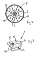
- the air vortex mill generally designated 1, comprises a stator cylinder 2 with rotor axis 3 arranged vertically rotatably therein.
- the rotor axis 3 is mounted outside the interior of the stator cylinder 2 and arranged along the longitudinal axis of the stator cylinder 2.
- On the rotor axis 3 are each a grinding stage forming rotor centrifugal disc 4 in the form of centrifugal discs 5 arranged peripherally between them grinding plates 6 rotatably.
- an electric motor 7 By means of an electric motor 7, the rotor axis 3 by means of a drive connection, not shown, to enable high speed in rotation.
- a finger sight 8 is also non-rotatably mounted on the rotor axis 3.
- the finger sight 8 consists of eight individual fingers 9, which have between them a wedge-shaped on the axis of the finger sight 8 forming axis 3 tapered column 10.
- the distance between two fingers 9 is 3 to 8 mm, preferably 8 mm.
- an annular cover plate 11th attached, preferably welded.
- a stator chamber 12 is formed between the finger sight 8 and the uppermost rotor-spinning plate 4, the height of which is determined by the distance between the uppermost centrifugal disk 5 and the finger sight 8.
- the stator chamber 12 open at the periphery of the wall of the stator cylinder 2 uniformly distributed air supply or Heileindüsungen 13 a. Through this, radially aligned to the rotor axis 3 air supply or Heileindüsungen 13 compressed air is blown into the stator chamber 12 by a arranged outside of the stator 2 circumferentially feed line 14.
- the product inlet opening 15 of a product return line 16 also opens into the stator chamber 12, through which coarse product is recycled into the interior of the stator cylinder 2.
- annular cover plate 17 Above the finger sight 8 is a from the wall of the stator 2 inwardly extending annular cover plate 17 is arranged with a central opening on the stator cylinder 2. Above the annular cover plate 17, a leading to a separation cyclone 18 product and air discharge line 19 opens into the interior of the stator cylinder 2 a.
- a fan 33 is attached to the rotatable rotor shaft 3, which causes the discharge of the milled product-air mixture from the stator cylinder 2 out and into the product and Heilabriostechnisch 19 into, but at least supportive.
- the separation cyclone 18 is equipped with a rotatable radial classifier wheel 21 driven by an electric motor 20, spaced at a distance of 15 to 25 mm rod-shaped fins 22 has.
- the air discharged from the stator cylinder 2 and the material having the desired grain spectrum, on the one hand, and the material to be recycled, on the other hand, are separated.
- the air and the material having the desired particle size distribution or the desired size enter from the cyclone 18 in a line 23, which leads to a bag filter, the exhaust gas downstream of an exhaust fan is connected.
- the product to be recycled is discharged from the separation cyclone 18 by means of a rotary valve 24 and returned to the area of the fluidized-fluid mill 1 or of the stator cylinder 2 with the aid of a further product return line 25.
- the product return lines 16, 25 open into a horizontally oriented third product return line 34, which opens into the interior of the stator cylinder 2 at the level of the lower two grinding stages of a total of seven defined by the refining plates 6 Mahllien the rotor centrifugal table.
- a driven by an electric motor 35 screw conveyor 36 is arranged, which enters the recirculated product or coarse grinding material in the interior of the stator cylinder 2.
- the targeted supply of the recirculated product to the lowest two grinding stages causes a good comminution of the product, since the first impact of the impact on the fineness of the resulting ground material significantly influenced and determined.
- an air supply connection 27 is arranged on this line.
- a main air supply line 26 of the air vortex mill 1 and the stator cylinder 2 is supplied in the direction of arrow 28 air.
- the main air supply line 26 opens into one in the lower Arranged in the region of the stator cylinder 2 main air supply chamber 29 with a central, near-axis main air supply opening 30 into the interior of the stator cylinder second
- the product to be ground in the fluidized-fluid mill 1 is fed by means of a feed line 32 having a feed screw 31 and opening into the stator cylinder 2 at the level of the lower centrifugal discs 5 and the lower two grinding stages.
- the product enters in the direction of arrow 37 in the supply line 32 and is comminuted in the area formed by the centrifugal discs 5 and the Rotorschleudertellern 4 grinding stages and then transported by flowing through the stator chamber 12 by means of the fan wheel 33 through the conduit 19 into the separation cyclone 18 and discharged through the line 23.
- Too coarse grain is returned via the product return line 16 or, if it is first deposited in the separation cyclone 18, through the product return line 25 to the third product return line 34 and then back to the grinding area of the fluidized air mill 1.
- a distributor wheel 38 is arranged centrally in the area of the main air feed opening 34 in the interior of the stator cylinder 2.
- this distributor wheel has the effect that by means of the screw conveyor 36, recycled coarse product introduced into the interior of the stator cylinder 2 is well distributed below the rotor squeegee plate 4 and then fed to the annular gap formed between the paint plates 6 and the inner wall of the stator cylinder 2, the actual grinding gap.
- a pipe 39 opening into the interior of the stator cylinder 2 or a pipe connecting piece is provided, through which coating material can be introduced into the interior of the stator cylinder 2.
- the coating material can be introduced into the interior of the stator cylinder 2 by means of a pump in liquid form or by means of a further screw in solid form. There, the coating material then wets and occupies the surfaces of the material to be ground during the milling process.
- Air is injected into the stator chamber 12 through the air feeds 13 at a pressure of 1 to 4 bar, preferably in the range of 3 to 4 bar.
- This air injection prevents the resultant ground product from sticking to the inner walls of the stator cylinder 2, the finger sight 8 or other areas of the fluidized-fluid mill 1, which then leads to clogging of the fluidized-fluid mill and a loss of throughput. It has pointed out that alone the formation of the air supply openings 13, without the injection of air is carried out at elevated pressure, may not cause the sticking and baking of the product preventing swirling in the stator chamber 12. Since negative pressure prevails in the interior of the stator cylinder 2, air would be sucked into the interior of the stator cylinder 2 through air inlets connected to the outside atmosphere, but this does not sufficiently ensure the necessary turbulence.
- the titanium dioxide pigment material milled in the fluidized-fluid mill 1 is extremely hard and abrasive, so that the refiner plates 6, but also the surface of the fan wheel 33 and the fins 22 of the radial classifier wheel 21 are coated with abrasion-resistant materials.
- the abrasion resistant material may be a ceramic material, i. a ceramic or metallic coating. But it is also possible that the refining plates 6, the fan wheel 33 and / or the Radialsichterrad 21 and its fins 22 are made of ceramic.
- a particularly effective grinding plate 6 is in the Fig. 3 shown.
- Such a grinding plate consists of a flat base plate 40, on whose upper sides in the region of the front grinding edge in each case a bow-shaped, further plate 41, 42 is arranged vertically.
- the bar and bow-shaped plates 41, 42 are rounded at their corner regions and form with the base plate 40 for the grinding of titanium dioxide pigment material particularly effective grinding plate 6 from.
- the refining plate 6 can be fastened to Rotorschleudertellern 4.
- the lowest two Mahltren are advantageously with such a refining plate fitted. Due to its design, this refining plate has a plurality of grinding points or grinding surfaces, so that the pigment material can be ground particularly finely therewith.
- a process diagram which schematically illustrates the arrangement of the grinding and / or deagglomeration treatment step or step in the context of a titanium dioxide pigment production process is known from US Pat Fig. 4 seen.
- the Fig. 4 shows in the lines AD schematically processes in which titanium dioxide pigment material is subjected in the course of a grinding and / or deagglomeration treatment stage of a grinding 44 in an air vortex mill 1 according to the invention.
- Line A shows the preparation of untreated rutile in a roll milling 48 subsequent grinding and / or deagglomeration treatment step 44 with the fluidized fluid mill 1.
- This sequence of the titanium dioxide pigment production process comprises the calcination 45 of the titanium dioxide pigment material, the subsequent silo storage 46 and the subsequent coating 47, after which the titanium dioxide pigment material is subjected to roll milling 48 before the grinding and / or deagglomeration treatment step 44 in the fluidized air mill 1 is then followed. Subsequently, the ground titanium dioxide pigment material is fed by means of a pneumatic conveying 49 to a bagging / packaging 50.
- the line B schematically represents the same process step sequence as in the case A, although the roll grinding stage 48 is dispensed with.
- the corresponding process steps or process steps are provided with the same reference numerals. While in case A the grinding and / or deagglomeration treatment stage comprises both a roll milling 48 and a grinding and / or deagglomeration treatment step 44 in an air fluidized bed mill 1, in case B the grinding and / or deagglomeration treatment step 44 consists solely of fluidized air mill grinding.
- Lines C and D schematically illustrate the sequence of process steps / steps in the production of an aftertreatment precursor in which a milling and / or deagglomeration treatment step 44 using the fluidized air mill 1 is again provided.
- Calcination 45 and silo storage 46 are followed by roll milling 48 in case C, which then follows the fluidized-fluid mill grinding stage 44.
- case D the roll milling 48 is omitted.
- the step or step 44 is then followed by a suspending step 51 before the titanium dioxide pigment material is then subjected to a post-treatment 52.
- the air vortex mill 1 is supplied with moist product via the screw 31.
- This may in particular be titanium dioxide filter cake material obtained in titanium dioxide pigment production. But the Mahldrocknung of other filter cake, pigment filter cake, pigment suspensions or pigment precursors is possible.
- the moist material contains titanium hydrate or a mixture containing titanium hydride or it is a titanium dioxide suspension or a titanium dioxide filter cake, as usually obtained in the production process by the sulphate process.
- both the grinding and the drying or a certain drying of the introduced material takes place in the interior of the stator.
- Preheated, heated or heated air is preferably supplied through the air supply port 27 of the main air chamber 29 during the mill drying.
Landscapes
- Engineering & Computer Science (AREA)
- Food Science & Technology (AREA)
- Chemical & Material Sciences (AREA)
- Organic Chemistry (AREA)
- Pigments, Carbon Blacks, Or Wood Stains (AREA)
- Inorganic Compounds Of Heavy Metals (AREA)
- Crushing And Grinding (AREA)
Priority Applications (1)
| Application Number | Priority Date | Filing Date | Title |
|---|---|---|---|
| PL06762387T PL1902103T3 (pl) | 2005-07-09 | 2006-07-04 | Wytwarzanie pigmentu ditlenku tytanu z użyciem młyna cyklonowego |
Applications Claiming Priority (2)
| Application Number | Priority Date | Filing Date | Title |
|---|---|---|---|
| DE102005032248A DE102005032248B4 (de) | 2005-07-09 | 2005-07-09 | Titandioxidpigmentherstellung unter Verwendung einer Luftwirbelmühle |
| PCT/EP2006/006496 WO2007006456A2 (de) | 2005-07-09 | 2006-07-04 | Titandioxidpigmentherstellung unter verwendung einer luftwirbelmühle |
Publications (2)
| Publication Number | Publication Date |
|---|---|
| EP1902103A2 EP1902103A2 (de) | 2008-03-26 |
| EP1902103B1 true EP1902103B1 (de) | 2009-01-07 |
Family
ID=37562613
Family Applications (1)
| Application Number | Title | Priority Date | Filing Date |
|---|---|---|---|
| EP06762387A Revoked EP1902103B1 (de) | 2005-07-09 | 2006-07-04 | Titandioxidpigmentherstellung unter verwendung einer luftwirbelmühle |
Country Status (6)
| Country | Link |
|---|---|
| EP (1) | EP1902103B1 (pl) |
| AT (1) | ATE420143T1 (pl) |
| DE (2) | DE102005032248B4 (pl) |
| ES (1) | ES2320696T3 (pl) |
| PL (1) | PL1902103T3 (pl) |
| WO (1) | WO2007006456A2 (pl) |
Families Citing this family (5)
| Publication number | Priority date | Publication date | Assignee | Title |
|---|---|---|---|---|
| DE102006049495B4 (de) * | 2006-03-07 | 2009-09-03 | Tronox Pigments Gmbh | Verfahren zur Mahlung und Dispergierung von Klinker |
| CN112705315A (zh) * | 2020-12-21 | 2021-04-27 | 衢州创普机械设备有限公司 | 一种金属废料加工设备 |
| CN116907939A (zh) * | 2023-06-28 | 2023-10-20 | 青岛市农业科学研究院(山东省农业科学院青岛市分院) | 一种果树成分分析用可控风选研磨装置及方法 |
| IT202300014592A1 (it) * | 2023-07-12 | 2025-01-12 | Vortex Srl Sb | Metodo ed apparecchiatura per produzione di polvere e pasta di frutta |
| EP4527506A1 (de) * | 2023-09-22 | 2025-03-26 | Josef Fischer | Glasmehlerzeugungsverfahren und glasmehlerzeugungsvorrichtung |
Family Cites Families (4)
| Publication number | Priority date | Publication date | Assignee | Title |
|---|---|---|---|---|
| DE1164805B (de) * | 1958-11-18 | 1964-03-05 | Altenburger Maschinen K G Jaec | Schlaegermuehle mit vertikal gelagertem Schlaegerrotor |
| DE3543370A1 (de) * | 1985-12-07 | 1987-06-11 | Jackering Altenburger Masch | Muehle mit mehreren mahlstufen |
| DE19611112C2 (de) * | 1996-03-21 | 2002-04-18 | Jackering Altenburger Masch | Verfahren und Vorrichtung zur Herstellung von extrem feinen Pulvern |
| DE19823563A1 (de) * | 1998-05-27 | 1999-12-02 | Altenburger Masch Gmbh | Mahltrocknung von Zellulose-Derivaten, insbesondere Methl-Zellulose |
-
2005
- 2005-07-09 DE DE102005032248A patent/DE102005032248B4/de not_active Revoked
-
2006
- 2006-07-04 EP EP06762387A patent/EP1902103B1/de not_active Revoked
- 2006-07-04 ES ES06762387T patent/ES2320696T3/es active Active
- 2006-07-04 DE DE502006002597T patent/DE502006002597D1/de active Active
- 2006-07-04 AT AT06762387T patent/ATE420143T1/de not_active IP Right Cessation
- 2006-07-04 WO PCT/EP2006/006496 patent/WO2007006456A2/de not_active Ceased
- 2006-07-04 PL PL06762387T patent/PL1902103T3/pl unknown
Also Published As
| Publication number | Publication date |
|---|---|
| WO2007006456A2 (de) | 2007-01-18 |
| ATE420143T1 (de) | 2009-01-15 |
| DE502006002597D1 (de) | 2009-02-26 |
| DE102005032248B4 (de) | 2009-04-23 |
| DE102005032248A1 (de) | 2007-01-11 |
| PL1902103T3 (pl) | 2009-06-30 |
| ES2320696T3 (es) | 2009-05-27 |
| WO2007006456A3 (de) | 2007-05-24 |
| EP1902103A2 (de) | 2008-03-26 |
Similar Documents
| Publication | Publication Date | Title |
|---|---|---|
| EP2637790B1 (de) | Verfahren zur zerkleinerung von mahlgut und wälzmühle | |
| DE69704110T2 (de) | Verbesserte fluidenergie-mühle | |
| EP2632599B1 (de) | Rührwerkskugelmühle | |
| DE4447321C2 (de) | Rührwerksmühle für die nasse Feinzerkleinerung, mit Separator zur Zurückhaltung von Mahlperlen | |
| EP2869928B1 (de) | Verfahren zum betrieb einer rührwerkskugelmühle sowie rührwerkskugelmühle dafür | |
| EP3292912B1 (de) | Verfahren zum betrieb eines multizyklons zum trennen von fein- und feinstkorn sowie multizyklon | |
| DE102007005250B3 (de) | Verfahren zum kontinuierlichen Trockenmahlbetrieb einer Turmreibmühle und Turmreibmühle | |
| DE4323587C2 (de) | Verfahren und Einrichtung zum Zerkleinern von Material unterschiedlicher Körnung | |
| EP0460490B1 (de) | Sichter | |
| EP2694215B1 (de) | Verfahren und vorrichtung zur vermahlung von feuchtem material | |
| WO1992003227A1 (de) | Vertikalprallmühle mit integrierter materialklassierung | |
| DE102020006008B3 (de) | Fließbettgegenstrahlmühle zur Erzeugung feinster Partikel aus Aufgabegut geringer Schüttdichte und Verfahren dafür | |
| EP0261241B1 (de) | Desintegrator | |
| EP1948360B1 (de) | Wälzmühle | |
| EP1902103B1 (de) | Titandioxidpigmentherstellung unter verwendung einer luftwirbelmühle | |
| EP1430951A1 (de) | Kreislaufmahleinrichtung mit Mühle und Sichter | |
| DE68926105T2 (de) | Vorrichtung und verfahren zum mahlen und pulverisieren | |
| EP0887106B1 (de) | Kreislaufmahleinrichtung mit Hochdruck-Walzenpresse und Sichter | |
| EP1896184A2 (de) | Verfahren und vorrichtung zur erzaufbereitung | |
| EP2992960B1 (de) | Vorrichtung zum zerkleinern von aufgabegut mit vorgeschalteter sichtung | |
| DE19723705C1 (de) | Mühle zum schonenden Feinstvermahlen von Produkten unterschiedlicher Herkunft | |
| EP0801985B1 (de) | Hockdruck-Walzenpresse zur Druckzerkleinerung von körnigem Gutmaterial | |
| DE19700429A1 (de) | Mühle | |
| DE7300113U (de) | Muehle zur feinzerkleinerung von partikelfoermigem material | |
| EP3691799B1 (de) | Siebvorrichtung |
Legal Events
| Date | Code | Title | Description |
|---|---|---|---|
| PUAI | Public reference made under article 153(3) epc to a published international application that has entered the european phase |
Free format text: ORIGINAL CODE: 0009012 |
|
| 17P | Request for examination filed |
Effective date: 20080103 |
|
| AK | Designated contracting states |
Kind code of ref document: A2 Designated state(s): AT BE BG CH CY CZ DE DK EE ES FI FR GB GR HU IE IS IT LI LT LU LV MC NL PL PT RO SE SI SK TR |
|
| DAX | Request for extension of the european patent (deleted) | ||
| GRAP | Despatch of communication of intention to grant a patent |
Free format text: ORIGINAL CODE: EPIDOSNIGR1 |
|
| GRAS | Grant fee paid |
Free format text: ORIGINAL CODE: EPIDOSNIGR3 |
|
| GRAA | (expected) grant |
Free format text: ORIGINAL CODE: 0009210 |
|
| AK | Designated contracting states |
Kind code of ref document: B1 Designated state(s): AT BE BG CH CY CZ DE DK EE ES FI FR GB GR HU IE IS IT LI LT LU LV MC NL PL PT RO SE SI SK TR |
|
| REG | Reference to a national code |
Ref country code: GB Ref legal event code: FG4D Free format text: NOT ENGLISH |
|
| REG | Reference to a national code |
Ref country code: CH Ref legal event code: EP |
|
| REG | Reference to a national code |
Ref country code: IE Ref legal event code: FG4D Free format text: LANGUAGE OF EP DOCUMENT: GERMAN |
|
| REF | Corresponds to: |
Ref document number: 502006002597 Country of ref document: DE Date of ref document: 20090226 Kind code of ref document: P |
|
| REG | Reference to a national code |
Ref country code: ES Ref legal event code: FG2A Ref document number: 2320696 Country of ref document: ES Kind code of ref document: T3 |
|
| PG25 | Lapsed in a contracting state [announced via postgrant information from national office to epo] |
Ref country code: SI Free format text: LAPSE BECAUSE OF FAILURE TO SUBMIT A TRANSLATION OF THE DESCRIPTION OR TO PAY THE FEE WITHIN THE PRESCRIBED TIME-LIMIT Effective date: 20090107 Ref country code: NL Free format text: LAPSE BECAUSE OF FAILURE TO SUBMIT A TRANSLATION OF THE DESCRIPTION OR TO PAY THE FEE WITHIN THE PRESCRIBED TIME-LIMIT Effective date: 20090107 |
|
| NLV1 | Nl: lapsed or annulled due to failure to fulfill the requirements of art. 29p and 29m of the patents act | ||
| REG | Reference to a national code |
Ref country code: PL Ref legal event code: T3 |
|
| PG25 | Lapsed in a contracting state [announced via postgrant information from national office to epo] |
Ref country code: LT Free format text: LAPSE BECAUSE OF FAILURE TO SUBMIT A TRANSLATION OF THE DESCRIPTION OR TO PAY THE FEE WITHIN THE PRESCRIBED TIME-LIMIT Effective date: 20090107 |
|
| REG | Reference to a national code |
Ref country code: IE Ref legal event code: FD4D |
|
| PG25 | Lapsed in a contracting state [announced via postgrant information from national office to epo] |
Ref country code: PT Free format text: LAPSE BECAUSE OF FAILURE TO SUBMIT A TRANSLATION OF THE DESCRIPTION OR TO PAY THE FEE WITHIN THE PRESCRIBED TIME-LIMIT Effective date: 20090608 Ref country code: IS Free format text: LAPSE BECAUSE OF FAILURE TO SUBMIT A TRANSLATION OF THE DESCRIPTION OR TO PAY THE FEE WITHIN THE PRESCRIBED TIME-LIMIT Effective date: 20090507 Ref country code: SE Free format text: LAPSE BECAUSE OF FAILURE TO SUBMIT A TRANSLATION OF THE DESCRIPTION OR TO PAY THE FEE WITHIN THE PRESCRIBED TIME-LIMIT Effective date: 20090407 Ref country code: LV Free format text: LAPSE BECAUSE OF FAILURE TO SUBMIT A TRANSLATION OF THE DESCRIPTION OR TO PAY THE FEE WITHIN THE PRESCRIBED TIME-LIMIT Effective date: 20090107 |
|
| PLBI | Opposition filed |
Free format text: ORIGINAL CODE: 0009260 |
|
| PG25 | Lapsed in a contracting state [announced via postgrant information from national office to epo] |
Ref country code: IE Free format text: LAPSE BECAUSE OF FAILURE TO SUBMIT A TRANSLATION OF THE DESCRIPTION OR TO PAY THE FEE WITHIN THE PRESCRIBED TIME-LIMIT Effective date: 20090107 Ref country code: EE Free format text: LAPSE BECAUSE OF FAILURE TO SUBMIT A TRANSLATION OF THE DESCRIPTION OR TO PAY THE FEE WITHIN THE PRESCRIBED TIME-LIMIT Effective date: 20090107 Ref country code: DK Free format text: LAPSE BECAUSE OF FAILURE TO SUBMIT A TRANSLATION OF THE DESCRIPTION OR TO PAY THE FEE WITHIN THE PRESCRIBED TIME-LIMIT Effective date: 20090107 Ref country code: CZ Free format text: LAPSE BECAUSE OF FAILURE TO SUBMIT A TRANSLATION OF THE DESCRIPTION OR TO PAY THE FEE WITHIN THE PRESCRIBED TIME-LIMIT Effective date: 20090107 |
|
| PLAX | Notice of opposition and request to file observation + time limit sent |
Free format text: ORIGINAL CODE: EPIDOSNOBS2 |
|
| 26 | Opposition filed |
Opponent name: ALTENBURGER MASCHINEN JAECKERING GMBH Effective date: 20091007 Opponent name: OMYA DEVELOPMENT AG Effective date: 20091006 |
|
| PG25 | Lapsed in a contracting state [announced via postgrant information from national office to epo] |
Ref country code: RO Free format text: LAPSE BECAUSE OF FAILURE TO SUBMIT A TRANSLATION OF THE DESCRIPTION OR TO PAY THE FEE WITHIN THE PRESCRIBED TIME-LIMIT Effective date: 20090107 Ref country code: SK Free format text: LAPSE BECAUSE OF FAILURE TO SUBMIT A TRANSLATION OF THE DESCRIPTION OR TO PAY THE FEE WITHIN THE PRESCRIBED TIME-LIMIT Effective date: 20090107 |
|
| PG25 | Lapsed in a contracting state [announced via postgrant information from national office to epo] |
Ref country code: BG Free format text: LAPSE BECAUSE OF FAILURE TO SUBMIT A TRANSLATION OF THE DESCRIPTION OR TO PAY THE FEE WITHIN THE PRESCRIBED TIME-LIMIT Effective date: 20090407 |
|
| BERE | Be: lapsed |
Owner name: TRONOX PIGMENTS G.M.B.H. Effective date: 20090731 |
|
| PG25 | Lapsed in a contracting state [announced via postgrant information from national office to epo] |
Ref country code: MC Free format text: LAPSE BECAUSE OF NON-PAYMENT OF DUE FEES Effective date: 20090731 |
|
| PLBB | Reply of patent proprietor to notice(s) of opposition received |
Free format text: ORIGINAL CODE: EPIDOSNOBS3 |
|
| PG25 | Lapsed in a contracting state [announced via postgrant information from national office to epo] |
Ref country code: BE Free format text: LAPSE BECAUSE OF NON-PAYMENT OF DUE FEES Effective date: 20090731 |
|
| RAP2 | Party data changed (patent owner data changed or rights of a patent transferred) |
Owner name: CRENOX GMBH |
|
| REG | Reference to a national code |
Ref country code: ES Ref legal event code: FD2A Effective date: 20090706 |
|
| PG25 | Lapsed in a contracting state [announced via postgrant information from national office to epo] |
Ref country code: GR Free format text: LAPSE BECAUSE OF FAILURE TO SUBMIT A TRANSLATION OF THE DESCRIPTION OR TO PAY THE FEE WITHIN THE PRESCRIBED TIME-LIMIT Effective date: 20090408 Ref country code: ES Free format text: LAPSE BECAUSE OF NON-PAYMENT OF DUE FEES Effective date: 20090706 |
|
| PG25 | Lapsed in a contracting state [announced via postgrant information from national office to epo] |
Ref country code: AT Free format text: LAPSE BECAUSE OF NON-PAYMENT OF DUE FEES Effective date: 20090704 |
|
| PGFP | Annual fee paid to national office [announced via postgrant information from national office to epo] |
Ref country code: DE Payment date: 20100802 Year of fee payment: 5 Ref country code: FI Payment date: 20100721 Year of fee payment: 5 Ref country code: FR Payment date: 20100802 Year of fee payment: 5 |
|
| PGFP | Annual fee paid to national office [announced via postgrant information from national office to epo] |
Ref country code: GB Payment date: 20100726 Year of fee payment: 5 Ref country code: PL Payment date: 20100630 Year of fee payment: 5 |
|
| REG | Reference to a national code |
Ref country code: CH Ref legal event code: PL |
|
| PG25 | Lapsed in a contracting state [announced via postgrant information from national office to epo] |
Ref country code: IT Free format text: LAPSE BECAUSE OF FAILURE TO SUBMIT A TRANSLATION OF THE DESCRIPTION OR TO PAY THE FEE WITHIN THE PRESCRIBED TIME-LIMIT Effective date: 20090107 |
|
| PG25 | Lapsed in a contracting state [announced via postgrant information from national office to epo] |
Ref country code: CH Free format text: LAPSE BECAUSE OF NON-PAYMENT OF DUE FEES Effective date: 20100731 Ref country code: LI Free format text: LAPSE BECAUSE OF NON-PAYMENT OF DUE FEES Effective date: 20100731 Ref country code: LU Free format text: LAPSE BECAUSE OF NON-PAYMENT OF DUE FEES Effective date: 20090704 |
|
| PG25 | Lapsed in a contracting state [announced via postgrant information from national office to epo] |
Ref country code: HU Free format text: LAPSE BECAUSE OF FAILURE TO SUBMIT A TRANSLATION OF THE DESCRIPTION OR TO PAY THE FEE WITHIN THE PRESCRIBED TIME-LIMIT Effective date: 20090708 |
|
| PG25 | Lapsed in a contracting state [announced via postgrant information from national office to epo] |
Ref country code: TR Free format text: LAPSE BECAUSE OF FAILURE TO SUBMIT A TRANSLATION OF THE DESCRIPTION OR TO PAY THE FEE WITHIN THE PRESCRIBED TIME-LIMIT Effective date: 20090107 |
|
| PG25 | Lapsed in a contracting state [announced via postgrant information from national office to epo] |
Ref country code: CY Free format text: LAPSE BECAUSE OF FAILURE TO SUBMIT A TRANSLATION OF THE DESCRIPTION OR TO PAY THE FEE WITHIN THE PRESCRIBED TIME-LIMIT Effective date: 20090107 |
|
| GBPC | Gb: european patent ceased through non-payment of renewal fee |
Effective date: 20110704 |
|
| REG | Reference to a national code |
Ref country code: FR Ref legal event code: ST Effective date: 20120330 |
|
| PLAB | Opposition data, opponent's data or that of the opponent's representative modified |
Free format text: ORIGINAL CODE: 0009299OPPO |
|
| PLBP | Opposition withdrawn |
Free format text: ORIGINAL CODE: 0009264 |
|
| PG25 | Lapsed in a contracting state [announced via postgrant information from national office to epo] |
Ref country code: FR Free format text: LAPSE BECAUSE OF NON-PAYMENT OF DUE FEES Effective date: 20110801 Ref country code: DE Free format text: LAPSE BECAUSE OF NON-PAYMENT OF DUE FEES Effective date: 20120201 |
|
| REG | Reference to a national code |
Ref country code: DE Ref legal event code: R119 Ref document number: 502006002597 Country of ref document: DE Effective date: 20120201 |
|
| R26 | Opposition filed (corrected) |
Opponent name: ALTENBURGER MASCHINEN JAECKERING GMBH Effective date: 20091007 Opponent name: OMYA DEVELOPMENT AG Effective date: 20091006 |
|
| PG25 | Lapsed in a contracting state [announced via postgrant information from national office to epo] |
Ref country code: FI Free format text: LAPSE BECAUSE OF NON-PAYMENT OF DUE FEES Effective date: 20110704 |
|
| PG25 | Lapsed in a contracting state [announced via postgrant information from national office to epo] |
Ref country code: GB Free format text: LAPSE BECAUSE OF NON-PAYMENT OF DUE FEES Effective date: 20110704 |
|
| PG25 | Lapsed in a contracting state [announced via postgrant information from national office to epo] |
Ref country code: PL Free format text: LAPSE BECAUSE OF NON-PAYMENT OF DUE FEES Effective date: 20110704 |
|
| REG | Reference to a national code |
Ref country code: PL Ref legal event code: LAPE |
|
| RDAF | Communication despatched that patent is revoked |
Free format text: ORIGINAL CODE: EPIDOSNREV1 |
|
| RDAG | Patent revoked |
Free format text: ORIGINAL CODE: 0009271 |
|
| STAA | Information on the status of an ep patent application or granted ep patent |
Free format text: STATUS: PATENT REVOKED |
|
| 27W | Patent revoked |
Effective date: 20130606 |
|
| REG | Reference to a national code |
Ref country code: AT Ref legal event code: MA03 Ref document number: 420143 Country of ref document: AT Kind code of ref document: T Effective date: 20130606 |