EP1901142B1 - Optimiertes Materialtrennungsverfahren - Google Patents
Optimiertes Materialtrennungsverfahren Download PDFInfo
- Publication number
- EP1901142B1 EP1901142B1 EP06120828.6A EP06120828A EP1901142B1 EP 1901142 B1 EP1901142 B1 EP 1901142B1 EP 06120828 A EP06120828 A EP 06120828A EP 1901142 B1 EP1901142 B1 EP 1901142B1
- Authority
- EP
- European Patent Office
- Prior art keywords
- separation process
- optimising
- model
- separating
- separation
- Prior art date
- Legal status (The legal status is an assumption and is not a legal conclusion. Google has not performed a legal analysis and makes no representation as to the accuracy of the status listed.)
- Active
Links
Images

Classifications
-
- G—PHYSICS
- G05—CONTROLLING; REGULATING
- G05B—CONTROL OR REGULATING SYSTEMS IN GENERAL; FUNCTIONAL ELEMENTS OF SUCH SYSTEMS; MONITORING OR TESTING ARRANGEMENTS FOR SUCH SYSTEMS OR ELEMENTS
- G05B13/00—Adaptive control systems, i.e. systems automatically adjusting themselves to have a performance which is optimum according to some preassigned criterion
- G05B13/02—Adaptive control systems, i.e. systems automatically adjusting themselves to have a performance which is optimum according to some preassigned criterion electric
- G05B13/04—Adaptive control systems, i.e. systems automatically adjusting themselves to have a performance which is optimum according to some preassigned criterion electric involving the use of models or simulators
- G05B13/048—Adaptive control systems, i.e. systems automatically adjusting themselves to have a performance which is optimum according to some preassigned criterion electric involving the use of models or simulators using a predictor
Definitions
- the present invention relates to material separation processes.
- the invention more particularly relates to a method, device and computer program product for controlling a material separation process as well as to a material separating system.
- the present invention is therefore directed towards providing a more efficient control of a material separation process.
- One object of the present invention is thus to provide a method for controlling a material separation process that makes the material separation process more efficient.
- This object is according to a first aspect of the present invention achieved through a method for controlling a material separation process, comprising the steps of:
- Another object of the present invention is to provide a device for controlling a material separation process that makes the material separation process more efficient.
- This object is according to a second aspect of the present invention achieved through a device for controlling a material separation process, comprising:
- Another object of the present invention is to provide a material separating system that provides a more efficient material separation process.
- This object is according to a third aspect of the present invention achieved through a material separating system comprising:
- Another object of the present invention is to provide a computer program product for controlling a material separation process that makes the material separation process more efficient.
- This object is according to a fourth aspect of the present invention also achieved through a computer program product for controlling a material separation process, comprising computer program code to make a computer perform when said code is loaded into said computer:
- the present invention has many advantages. It provides an efficient material separation process, where a plant is operated at or close to its optimal condition. Furthermore, a high concentration of the desired material is obtained together with a high recovery of the desired material and a low consumption of additives.
- Fig. 1 schematically shows a simplified exemplifying material separating system 10 according to the present invention, in the form of a simple flotation system.
- a fresh feeding unit 12 which provides a first material stream of bulk material, here in the form of pulp comprising a desired material and at least one undesired material.
- the desired material is here to be separated form the undesired material.
- the pulp is here furthermore provided in the form of a power. It is possible that the system could include an earlier stage before the feeding unit 12, where this powder was provided through grinding solid bulk material.
- the fresh feeding unit 12 is connected to a material adding unit 14, where a second material stream is combined with the first material stream.
- the material adding unit 14 is in turn connected to and supplies the pulp and the material of the second stream to a first material separating unit, here in the form of a first flotation cell 16, which is here a tank that is also denoted a rougher.
- the first flotation cell 16 contains water and is connected to a first additives supply unit 18 supplying additives to the water in the tank 16, with a first mixer 20 that mixes the water in the tank with the additives from the first additives supply unit 18, and with a first air supply unit 23.
- the first air supply unit 23 is here connected to a first air regulating unit 22, regulating the amount of air blown into the first flotation cell 16.
- the first cell 16 has a first outlet where separated output material, also denoted concentrate C is obtained.
- the output material includes the desired material in a certain ratio to an undesired material, also denoted gangue, in the pulp, and thus provides a certain grade, concentration or purity of the desired material. For a proper material separation process this ratio should be high.
- the first outlet is also provided with a first measuring unit 24, which measures some properties of the output material.
- This first measuring unit 24 is here preferably a refractometry device.
- the first cell 16 is also provided with a second outlet, which is connected to the inlet of a second material separating unit, here in the form of a second flotation cell 26.
- the second flotation cell 26 is here a tank that is also denoted a scavenger.
- the second flotation cell 26 contains water and is connected to a second additives supply unit 28 supplying additives to the water in the tank 26, with a second mixer 30 that mixes the water in the tank with the additives from the second additives supply unit 28, and with a second air supply unit 33.
- the second air supply unit 33 is here connected to a second air regulating unit 32, regulating the amount of air blown into the second flotation cell 26.
- the second cell 26 has a third outlet where output material, i.e. concentrate C is obtained. For these reasons the first and third outlets of the first and the second cells 16 and 26 are connected to each other.
- the third outlet is also provided with a second measuring unit 34, which measures some properties of the material.
- This measuring unit is here preferably a refractometry device.
- the second cell is also provided with a second outlet, which is connected to the above described material adding unit 14 in order to provide it with waste material W.
- This waste material is also denoted as tailings and also includes the desired material in a certain ratio to the undesired material. For a proper material separation process this ratio should be low.
- the measurement results of the first and second measuring units 24 and 34 are here provided to a device 36 controlling the material separation process, which in turn provides output signals used to control the first and second regulating units 22 and 32.
- the device 36 is provided with a state estimating unit 38 and an optimising unit 40. The details of this type of control will be discussed shortly.
- the fresh feeding unit 12 provides the pulp in the form of powder to the first flotation cell 16 via the material adding unit 14.
- the powder is mixed with water and additives are added from the first additive supply unit 18 through the operation of the first mixer 22.
- the mixer is like a big beater, which here rotates at a constant speed. Air is furthermore supplied from the first air supply unit 23. Because of this the desired material is separated from the undesired material, attaches itself to air bubbles and rises to the top of the tank in the form of a froth, which is scraped off.
- the remainder of the material, which is waste or tailings, is formed on the bottom of the cell and supplied to the second flotation cell 26, which applies the same procedure on the waste material in order to separate more desirable material from the undesirable material.
- the resulting output material, denoted concentrate C may then be supplied to another entity for further treatment, like a smelting plant, while the tailings W from the second cell 26 is provided to the material adding unit 14 in order to be combined with the fresh feed of pulp in order to enhance the recovery of the desired material.
- x denotes state variables
- u manipulated variables and x time derivates of state variables are here typically those variables that can be influenced by a control system in order to provide control
- state variables are variables indicative of the state of the process.
- Some of these state variables are process output variables.
- a measured output variable y may have a functional relationship g with a state variable x.
- the model is also associated with model constraints, e.g. limits for different manipulated variables and/or process output variables: a ⁇ u k ⁇ b d ⁇ x k ⁇ e
- a present or initial state of the process may be estimated.
- the state estimation is here carried out using moving horizon estimation (MHE) applied on the above mentioned function with the above mentioned constraints.
- MHE moving horizon estimation
- the state estimation is according to the present invention performed in the state estimating unit 38 of the device 36 and performed based on the output variables provided by the first and second measuring units 24 and 34.
- Optimising based on the model above is carried out through minimising an objective function.
- the objective function is formulated in accordance with the optimising aspects while considering the constraints and is preferably based on a comparison between the target trajectories of the controlled output process variables and controlled process output variables as predicted by the dynamic process model.
- optimised target trajectories or a range of set points are obtained which can be used for control.
- the set points described above generally refer to the control signals used for controlling the air supply to flotation cells.
- the range of set points takes constraints into account imposed by optimising aspects.
- the objective function is formulated in accordance with the optimizing aspects and is preferably based on a comparison between the target set of set points of the controlled process output variables and controlled process output variables as predicted but the dynamic process model.
- the computation is based on present values of state variables.
- the objective function is minimized by varying the input trajectories for the manipulated variables.
- the input trajectories giving the minimum of the objective function is thereby stated to be the optimum input trajectories.
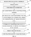
- a and B her denote the desired material and the undesired material, respectively. Based on these equations for a single cell a total model for the whole plant can then be obtained in dependence on how the cells of the plant are interconnected. How the control is carried out according to the present invention will now be described with reference being made to fig. 2 , which shows a flow chart outlining the general method steps for controlling the material separation process according to the present invention.
- process output variables are first received by the state estimating unit, step 42.
- the output signals from the first and second measuring units 24 and 34 are thus received from these signals it is then possible to determine the grade of concentration of the desired material, i.e. the percentage of the desired material in the output product. This may vary and for some materials 50% is normal.
- the data is then validated, step 44, and then state estimation is performed for determining an initial state, step 46. Constraints may in this regard be limitations on the feeding force, i.e. how much pulp may be fed in to the first flotation cell that concentrations are to be strictly positive, that the grade is supposed to be a certain number of percent, that the production speed is limited as well as different physical limitations of a cell.
- step 48 Thereafter constraints for a future prediction horizon are specified, step 48. Normally the same constraints would apply here as are used for the current state.
- the objective function parameters are then specified for this future horizon, step 50.
- the grade of concentration C of the output product is set to be above a specified level, i.e. the grade is defined as to have a certain minimum content of the desired material. This means that optimising is not made for maximising the grade.
- other variables may be set, like a fixed rotation speed on the mixers 20 and 30.
- the objective function is optimized, by the optimising unit 40, in order to obtain an input range of set values to use in controlling, step 52.
- the optimisation according to the present invention is here performed in order to maximize the recovery of the desired material of the process, i.e.
- the range of set points is associated with variations of the amount of air blown into a cell.
- the device 36 for controlling the material separation process is preferably provided in a computer.
- the state estimating and optimising units of the device may here be implemented through one or more processors together with computer program code for performing their functions.
- the program code mentioned above may also be provided as a computer program product, for instance in the form of one or more data carriers carrying computer program code for performing the functionality of the present invention when being loaded into the computer.
- One such carrier 58, in the form of a CD ROM disc is generally outlined in fig. 3 . It is however feasible with other data carriers.
- the computer program code can furthermore be provided as pure program code on an external server and downloaded to the computer in fig. 1 .
- the process was controlled through regulating the amount of air blown into a cell. It is just as well possible to regulate the amount of additives added, either instead of or in combination with the amount of air blown in as well as the froth level in the flotation cell through using a froth level control unit or similar unit in the flotation cell, where the input variables then would influence the set-point of the froth level control unit.
- the measured output variables need not be the concentrate, but also the waste may be measured, i.e. the amount of desirable material remaining in the tailings. In this regard there may be only one point where measurements are made in the system of fig. 1 . Other types of material separation processes can also be controlled in the same way.
Landscapes
- Engineering & Computer Science (AREA)
- Health & Medical Sciences (AREA)
- Artificial Intelligence (AREA)
- Computer Vision & Pattern Recognition (AREA)
- Evolutionary Computation (AREA)
- Medical Informatics (AREA)
- Software Systems (AREA)
- Physics & Mathematics (AREA)
- General Physics & Mathematics (AREA)
- Automation & Control Theory (AREA)
- Feedback Control In General (AREA)
- Paper (AREA)
Claims (28)
- Verfahren zum Steuern eines Materialtrennungsprozesses, umfassend die Schritte:Messen (42) mindestens einer Prozessausgangsvariable (C) bei dem Materialtrennungsprozess, die für den Trennungsgrad zwischen einem erwünschten Material und einem unerwünschten Material indikativ ist,Schätzen (46) des Zustands des Prozesses zu einem bestimmten Zeitpunkt durch Anwenden der gemessenen Ausgangsvariable und externer Randbedingungen für ein Vorhersagezeitintervall auf ein Modell des Materialtrennungsprozesses, wobei das Modell basiert auf mindestens einer Eingangsvariable, die manipuliert werden kann, mindestens zwei Ausgangsvariablen, die die gemessene Ausgangsvariable umfassen,Optimieren (52) einer Zielfunktion, die mindestens eine vorhergesagte gesteuerte Prozessausgangsvariable und die externen Randbedingungen involviert, wobei die vorhergesagte gesteuerte Prozessausgangsvariable durch das Prozessmodell basierend auf dem Zustand definiert ist und dieses Optimieren unter von dem Prozessmodell und/oder den externen Randbedingungen vorgegebenen Randbedingungen durch Anpassen der Eingangsvariablen erfolgt, was mindestens einen Sollwert für jede Eingangsvariable für das Vorhersagezeitintervall bereitstellt,dadurch gekennzeichnet, dass das Verfahren ferner den Schritt umfasst:Regulieren (56) des Trennungsprozesses durch Verwenden des Sollwerts, um den Trennungsprozess zum Trennen des erwünschten Materials von losem Material zu beeinflussen,wobei der Schritt zum Optimieren umfasst: Maximieren der Gewinnungsrate des erwünschten Materials in dem Trennungsprozess oder Minimieren der Menge an Additiven oder der verbrauchten Energiemenge.
- Verfahren nach Anspruch 1, wobei Optimierung umfasst: Halten einer ersten Menge an Ausgangsvariablen in Bezug auf den Trennungsgrad erwünschten Materials von unerwünschtem Material nahe bei einem spezifizierten Niveau.
- Verfahren nach Anspruch 1 oder 2, wobei das Modell nichtlinear ist.
- Verfahren nach Anspruch 3, wobei das Modell ein statisches Modell ist.
- Verfahren nach Anspruch 1 oder 2, wobei das Modell dynamisch ist und der Schritt zum Optimieren einen Bereich an Sollwerten für jede Eingangsvariable bereitstellt, wobei jeder Bereich Eingangstrajektorien für die manipulierten Variablen für das Vorhersagezeitintervall bereitstellt.
- Verfahren nach einem der vorhergehenden Ansprüche, wobei mindestens die Schritte zum Optimieren und Regulieren wiederholt in festen aufeinanderfolgenden Zeitintervallen durchgeführt werden.
- Verfahren nach einem der vorhergehenden Ansprüche, wobei der Trennungsprozess die Schritte umfasst: Zuführen eines losen Materials und Trennen eines erwünschten Materials von mindestens einem unerwünschten Material, welche beide in dem losen Material bereitgestellt sind.
- Verfahren nach Anspruch 7, wobei der Trennungsprozess ferner den Schritt umfasst: Rückführen von Restmaterial zurück ins lose Material zur Teilnahme an dem Trennungsschritt.
- Verfahren nach einem der vorhergehenden Ansprüche, wobei der Prozess ein Flotationsprozess ist.
- Verfahren nach Anspruch 9, wobei der Flotationsprozess umfasst: Mischen eines Pulvers aus nicht getrennten Materialien mit einem Fluid, Bewirken, dass das erwünschte Material von dem losen Material getrennt wird, und Bewirken, dass das erwünschte Material flotiert.
- Verfahren nach Anspruch 10, wobei die Eingangsvariablen bewirken, dass Luft in die Mischung geblasen wird.
- Verfahren nach Anspruch 10, wobei die Eingangsvariablen die Menge an Additiven beeinflussen, die der Mischung zugegeben werden.
- Verfahren nach Anspruch 10, wobei die Eingangsvariablen einen Schaumpegel bei dem Flotationsprozess beeinflussen.
- Einrichtung (36) zum Steuern eines Materialtrennungsprozesses, umfassend:eine Zustandsschätzeinheit (38), die dazu eingerichtet ist,mindestens eine gemessene Prozessausgangsvariable (C) bei dem Materialtrennungsprozess, die für den Trennungsgrad zwischen einem erwünschten Material und einem unerwünschten Material indikativ ist, zu empfangen, undden Zustand des Prozesses zu einem bestimmten Zeitpunkt durch Anwenden der gemessenen Ausgangsvariable und externer Randbedingungen für ein Vorhersagezeitintervall auf ein Modell des Materialtrennungsprozesses zu schätzen, wobei das Modell auf mindestens einer Eingangsvariable basiert, die manipuliert werden kann, und der Ausgangsvariable basiert, undeine Optimierungseinheit (40), die dazu eingerichtet ist,eine Zielfunktion zu optimieren, die mindestens eine vorhergesagte gesteuerte Prozessausgangsvariable und die externen Randbedingungen involviert, wobei die vorhergesagte gesteuerte Prozessausgangsvariable durch das Prozessmodell basierend auf dem Zustand definiert ist und dieses Optimieren unter von dem Prozessmodell und/oder den externen Randbedingungen vorgegebenen Randbedingungen durch Anpassen der Eingangsvariablen erfolgt,dadurch gekennzeichnet, dass die Optimierungseinheit ferner dazu eingerichtet ist,mindestens einen Sollwert für jede Eingangsvariable für das Vorhersagezeitintervall bereitzustellen zur Verwendung beim Regulieren des Trennungsprozesses, um den Trennungsprozess zum Trennen des erwünschten Materials von losem Material zu beeinflussen,wobei die Optimierungseinheit beim Optimieren der Zielfunktion ferner dazu eingerichtet ist, die Gewinnungsrate des erwünschten Materials in dem Trennungsprozess zu maximieren oder die Menge an Additiven oder die verbrauchte Energiemenge zu minimieren.
- Einrichtung nach Anspruch 14, wobei die Optimierungseinheit beim Optimieren der Zielfunktion dazu eingerichtet ist, eine erste Menge an Ausgangsvariablen in Bezug auf den Trennungsgrad erwünschten Materials von unerwünschtem Material nahe bei einem spezifizierten Niveau zu halten.
- Einrichtung nach Anspruch 14 oder 15, wobei das Modell dynamisch ist und die Optimierungseinheit dazu eingerichtet ist, einen Bereich an Sollwerten für jede Eingangsvariable bereitzustellen, wobei jeder Bereich Eingangstrajektorien für die manipulierten Variablen für das Vorhersagezeitintervall bereitstellt.
- Einrichtung nach Anspruch 14 oder 15, wobei das Modell nichtlinear ist.
- Einrichtung nach Anspruch 17, wobei das Modell ein statisches Modell ist.
- Einrichtung nach einem der Ansprüche 14 bis 18, wobei die Optimierungseinheit dazu eingerichtet ist, das Optimieren und Regulieren wiederholt in festen aufeinanderfolgenden Zeitintervallen durchzuführen.
- Materialtrennsystem (10), umfassend:mindestens eine Materialtrenneinheit (16, 26) zum Trennen erwünschten Materials von unerwünschtem Material,mindestens eine Messeinheit (24, 34), die dazu eingerichtet ist, mindestens eine Prozessausgangsvariable in dem Materialtrennungsprozess zu messen, die für den Trennungsgrad zwischen dem erwünschten Material und dem unerwünschten Material indikativ ist,eine Einrichtung nach Anspruch 14 zum Steuern eines Materialtrennungsprozesses,dadurch gekennzeichnet, dass das Materialtrennsystem ferner umfasst:mindestens eine Regulierungseinheit (22, 32), die dazu eingerichtet ist,den Trennungsprozess durch Verwenden des Sollwerts zu regulieren, um den Trennungsprozess zum Trennen des erwünschten Materials von losem Material zu beeinflussen,wobei die Einrichtung beim Optimieren der Zielfunktion ferner dazu eingerichtet ist, die Gewinnungsrate des erwünschten Materials in dem Trennungsprozess zu maximieren oder die Menge an Additiven oder die verbrauchte Energiemenge zu minimieren.
- Materialtrennsystem nach Anspruch 20, wobei der Materialtrenneinheit loses Material zugeführt wird und die Materialtrenneinheit dazu eingerichtet ist, das erwünschte Material von mindestens einem unerwünschten Material zu trennen, welche beide in dem losen Material bereitgestellt sind.
- Materialtrennsystem nach Anspruch 20, ferner umfassend eine Materialzugabeeinheit (14) zum Rückführen von Restmaterial zurück ins lose Material zur Teilnahme an der Trennung.
- Materialtrennsystem nach einem der Ansprüche 20 bis 21, wobei der Prozess ein Flotationsprozess ist.
- Materialtrennsystem nach Anspruch 22, ferner umfassend mindestens einen Mischer (20, 30) zum Mischen eines Pulvers aus nicht getrennten Materialien mit einem Fluid, eine Trennungsentität zum Bewirken, dass das erwünschte Material von dem losen Material getrennt wird, und/oder Bewirken, dass das erwünschte Material flotiert.
- Materialtrennsystem nach Anspruch 23, wobei die Trennungsentität eine Luftzufuhreinheit (23) umfasst und die Eingangsvariable die Luftzufuhreinheit steuert, um Luft in die Mischung zu blasen.
- Materialtrennsystem nach Anspruch 23, wobei die Trennungsentität eine Additivzufuhreinheit (18) umfasst und die Eingangsvariablen die Menge an Additiven beeinflussen, die der Mischung zugegeben werden.
- Materialtrennsystem nach Anspruch 23, wobei die Trennungsentität eine Schaumpegel-Steuereinheit oder dergleichen umfasst und die Eingangsvariablen den Sollwert der Schaumpegel-Steuereinheit beeinflussen.
- Computerprogrammprodukt (58) zum Steuern eines Materialtrennungsprozesses, umfassend Computerprogammcode, um einen Computer dazu zu veranlassen, wenn der Code in den Computer geladen ist, durchzuführen:Empfangen mindestens einer gemessenen Prozessausgangsvariable (C) bei dem Materialtrennungsprozess, die für den Trennungsgrad zwischen einem erwünschten Material und einem unerwünschten Material indikativ ist,Schätzen des Zustands des Prozesses zu einem bestimmten Zeitpunkt durch Anwenden der gemessenen Ausgangsvariable und externer Randbedingungen für ein Vorhersagezeitintervall auf ein Modell des Materialtrennungsprozesses, wobei das Modell auf mindestens einer Eingangsvariable, die manipuliert werden kann, und der Ausgangsvariable basiert,Optimieren einer Zielfunktion, die mindestens eine vorhergesagte gesteuerte Prozessausgangsvariable und die externen Randbedingungen involviert, wobei die vorhergesagte gesteuerte Prozessausgangsvariable durch das Prozessmodell basierend auf dem Zustand definiert ist und dieses Optimieren unter von dem Prozessmodell und/oder den externen Randbedingungen vorgegebenen Randbedingungen durch Anpassen der Eingangsvariablen erfolgt,dadurch gekennzeichnet, dass das Computerprogrammprodukt ferner Computerprogrammcode umfasst, um den Computer dazu zu veranlassen, wenn der Code in den Computer geladen ist, durchzuführen:Bereitstellen mindestens eines Sollwerts für jede Eingangsvariable für das Vorhersagezeitintervall zur Verwendung beim Regulieren des Trennungsprozesses, um den Trennungsprozess zum Trennen des erwünschten Materials von losem Material zu beeinflussen,wobei das Optimieren der Zielfunktion umfasst: Maximieren der Gewinnungsrate des erwünschten Materials in dem Trennungsprozess oder Minimieren der Menge an Additiven oder der verbrauchten Energiemenge.
Priority Applications (10)
| Application Number | Priority Date | Filing Date | Title |
|---|---|---|---|
| PL06120828T PL1901142T3 (pl) | 2006-09-18 | 2006-09-18 | Optymalizacja procesu rozdzielania materiałów |
| EP06120828.6A EP1901142B1 (de) | 2006-09-18 | 2006-09-18 | Optimiertes Materialtrennungsverfahren |
| CN2007800344267A CN101517497B (zh) | 2006-09-18 | 2007-09-17 | 材料分离过程的优化 |
| RU2009112490/08A RU2424546C2 (ru) | 2006-09-18 | 2007-09-17 | Способ и устройство для управления процессом разделения материала |
| CA2662189A CA2662189C (en) | 2006-09-18 | 2007-09-17 | Optimisation of a material separation process |
| BRPI0717033-5A2A BRPI0717033A2 (pt) | 2006-09-18 | 2007-09-17 | mÉtodo e dispositivo para controlar processo de separaÇço de material, sistema de separaÇço de material e produto de programa de computador para controlar processo de separaÇço de material |
| AU2007299014A AU2007299014B2 (en) | 2006-09-18 | 2007-09-17 | Optimisation of a material separation process |
| PCT/EP2007/059790 WO2008034800A1 (en) | 2006-09-18 | 2007-09-17 | Optimisation of a material separation process |
| ZA2009/01671A ZA200901671B (en) | 2006-09-18 | 2009-03-09 | Optimisation of a material separation process |
| US12/406,798 US9760066B2 (en) | 2006-09-18 | 2009-03-18 | Optimisation of a material separation process |
Applications Claiming Priority (1)
| Application Number | Priority Date | Filing Date | Title |
|---|---|---|---|
| EP06120828.6A EP1901142B1 (de) | 2006-09-18 | 2006-09-18 | Optimiertes Materialtrennungsverfahren |
Publications (2)
| Publication Number | Publication Date |
|---|---|
| EP1901142A1 EP1901142A1 (de) | 2008-03-19 |
| EP1901142B1 true EP1901142B1 (de) | 2018-01-10 |
Family
ID=37714359
Family Applications (1)
| Application Number | Title | Priority Date | Filing Date |
|---|---|---|---|
| EP06120828.6A Active EP1901142B1 (de) | 2006-09-18 | 2006-09-18 | Optimiertes Materialtrennungsverfahren |
Country Status (10)
| Country | Link |
|---|---|
| US (1) | US9760066B2 (de) |
| EP (1) | EP1901142B1 (de) |
| CN (1) | CN101517497B (de) |
| AU (1) | AU2007299014B2 (de) |
| BR (1) | BRPI0717033A2 (de) |
| CA (1) | CA2662189C (de) |
| PL (1) | PL1901142T3 (de) |
| RU (1) | RU2424546C2 (de) |
| WO (1) | WO2008034800A1 (de) |
| ZA (1) | ZA200901671B (de) |
Families Citing this family (2)
| Publication number | Priority date | Publication date | Assignee | Title |
|---|---|---|---|---|
| CN110520805B (zh) * | 2017-04-18 | 2022-12-06 | 首要金属科技德国有限责任公司 | 过程模型的建模优化 |
| CN112517248B (zh) * | 2020-10-29 | 2022-08-09 | 宜春钽铌矿有限公司 | 一种锂云母浮选系统液位的智能控制方法 |
Family Cites Families (6)
| Publication number | Priority date | Publication date | Assignee | Title |
|---|---|---|---|---|
| SU1685528A1 (ru) * | 1987-07-07 | 1991-10-23 | Производственное Объединение "Уралкалий" | Способ управлени процессом флотации |
| US5798917A (en) * | 1993-03-03 | 1998-08-25 | Slegten Societe Anonyme | Control process for closed-circuit dry-method grinder |
| WO2002072485A2 (en) * | 2001-02-23 | 2002-09-19 | V.A.I. Ltd. | Methods and apparatus for biological treatment of waste waters |
| US20030010112A1 (en) | 2001-07-11 | 2003-01-16 | David Yekutiely | Monitor and warning apparatus and methods |
| CN100337711C (zh) * | 2001-09-19 | 2007-09-19 | 拜尔技术服务有限责任公司 | 分离多种物质混合物的过程控制方法 |
| SE522691C3 (sv) * | 2002-06-12 | 2004-04-07 | Abb Ab | Dynamisk on-line-optimering av produktionsprocesser |
-
2006
- 2006-09-18 PL PL06120828T patent/PL1901142T3/pl unknown
- 2006-09-18 EP EP06120828.6A patent/EP1901142B1/de active Active
-
2007
- 2007-09-17 AU AU2007299014A patent/AU2007299014B2/en active Active
- 2007-09-17 BR BRPI0717033-5A2A patent/BRPI0717033A2/pt not_active Application Discontinuation
- 2007-09-17 WO PCT/EP2007/059790 patent/WO2008034800A1/en not_active Ceased
- 2007-09-17 CN CN2007800344267A patent/CN101517497B/zh active Active
- 2007-09-17 CA CA2662189A patent/CA2662189C/en active Active
- 2007-09-17 RU RU2009112490/08A patent/RU2424546C2/ru active
-
2009
- 2009-03-09 ZA ZA2009/01671A patent/ZA200901671B/en unknown
- 2009-03-18 US US12/406,798 patent/US9760066B2/en active Active
Non-Patent Citations (1)
| Title |
|---|
| None * |
Also Published As
| Publication number | Publication date |
|---|---|
| WO2008034800A1 (en) | 2008-03-27 |
| AU2007299014A1 (en) | 2008-03-27 |
| EP1901142A1 (de) | 2008-03-19 |
| RU2009112490A (ru) | 2010-10-27 |
| BRPI0717033A2 (pt) | 2013-10-01 |
| CA2662189A1 (en) | 2008-03-27 |
| US9760066B2 (en) | 2017-09-12 |
| PL1901142T3 (pl) | 2018-07-31 |
| CN101517497B (zh) | 2011-08-31 |
| CA2662189C (en) | 2015-06-09 |
| AU2007299014B2 (en) | 2011-03-24 |
| CN101517497A (zh) | 2009-08-26 |
| US20090234496A1 (en) | 2009-09-17 |
| RU2424546C2 (ru) | 2011-07-20 |
| ZA200901671B (en) | 2010-02-24 |
Similar Documents
| Publication | Publication Date | Title |
|---|---|---|
| EP2414901B1 (de) | System und verfahren zum überwachen eines integrierten systems | |
| EP2667974A2 (de) | Schaumschwimmkontrolle | |
| WO2017181222A1 (en) | Water treatment system and method | |
| JP3231164B2 (ja) | 浄水場凝集プロセスの制御装置 | |
| US9760066B2 (en) | Optimisation of a material separation process | |
| Tzoneva | Optimal PID control of the dissolved oxygen concentration in the wastewater treatment plant | |
| AU2013262465A1 (en) | Controlling froth flotation | |
| CN107247470B (zh) | 一种钾肥生产中再浆洗涤的自动控制系统 | |
| Chai et al. | A hybrid intelligent optimal control method for complex flotation process | |
| Osorio et al. | Assessment of expert fuzzy controllers for conventional flotation plants | |
| CN113813863B (zh) | 尾砂混合料含水量的调控方法及系统、电子设备和介质 | |
| US20140231360A1 (en) | NH3 Feed-Forward Control of Blower Output | |
| CA2512270C (en) | Method and means for sand reblending | |
| Cortés et al. | Rougher flotation multivariable predictive control: concentrator A-1 division Codelco Norte | |
| Quintanilla et al. | Centralised economic model predictive control of froth flotation banks with experimental implementation | |
| CN120005720B (zh) | 一种人工智能的细胞培养监测方法及系统 | |
| JP2002361299A (ja) | 汚泥の含水率調整方法及び装置 | |
| CA2816080C (en) | Controlling froth flotation | |
| SU1090447A1 (ru) | Устройство управлени измельчительно-флотационным циклом | |
| Bergh et al. | Operation of rougher flotation circuits aided by industrial simulator | |
| Rao et al. | Simulating surface aeration systems at different scale of mixing time | |
| Jämsä-Jounela et al. | A Simulation study of expert control system for a phosphate flotation process | |
| CN120507961A (zh) | 一种石灰石粉量的控制方法、系统及相关装置 | |
| Orchard et al. | Model Based Predictive Control With Fuzzy Characterization of Goals and Constraints, Applied to the Dynamic Optimization of Grinding Plants. | |
| CN121742250A (zh) | 基于机器视觉的发酵产物灭活过程泡沫监测与消抑泡系统 |
Legal Events
| Date | Code | Title | Description |
|---|---|---|---|
| PUAI | Public reference made under article 153(3) epc to a published international application that has entered the european phase |
Free format text: ORIGINAL CODE: 0009012 |
|
| AK | Designated contracting states |
Kind code of ref document: A1 Designated state(s): AT BE BG CH CY CZ DE DK EE ES FI FR GB GR HU IE IS IT LI LT LU LV MC NL PL PT RO SE SI SK TR |
|
| AX | Request for extension of the european patent |
Extension state: AL BA HR MK YU |
|
| 17P | Request for examination filed |
Effective date: 20080827 |
|
| 17Q | First examination report despatched |
Effective date: 20081006 |
|
| AKX | Designation fees paid |
Designated state(s): AT BE BG CH CY CZ DE DK EE ES FI FR GB GR HU IE IS IT LI LT LU LV MC NL PL PT RO SE SI SK TR |
|
| GRAP | Despatch of communication of intention to grant a patent |
Free format text: ORIGINAL CODE: EPIDOSNIGR1 |
|
| INTG | Intention to grant announced |
Effective date: 20170803 |
|
| GRAS | Grant fee paid |
Free format text: ORIGINAL CODE: EPIDOSNIGR3 |
|
| GRAA | (expected) grant |
Free format text: ORIGINAL CODE: 0009210 |
|
| AK | Designated contracting states |
Kind code of ref document: B1 Designated state(s): AT BE BG CH CY CZ DE DK EE ES FI FR GB GR HU IE IS IT LI LT LU LV MC NL PL PT RO SE SI SK TR |
|
| REG | Reference to a national code |
Ref country code: GB Ref legal event code: FG4D |
|
| REG | Reference to a national code |
Ref country code: CH Ref legal event code: EP Ref country code: AT Ref legal event code: REF Ref document number: 963048 Country of ref document: AT Kind code of ref document: T Effective date: 20180115 |
|
| REG | Reference to a national code |
Ref country code: IE Ref legal event code: FG4D |
|
| REG | Reference to a national code |
Ref country code: DE Ref legal event code: R096 Ref document number: 602006054508 Country of ref document: DE |
|
| REG | Reference to a national code |
Ref country code: SE Ref legal event code: TRGR |
|
| REG | Reference to a national code |
Ref country code: NL Ref legal event code: MP Effective date: 20180110 |
|
| REG | Reference to a national code |
Ref country code: AT Ref legal event code: MK05 Ref document number: 963048 Country of ref document: AT Kind code of ref document: T Effective date: 20180110 |
|
| PG25 | Lapsed in a contracting state [announced via postgrant information from national office to epo] |
Ref country code: NL Free format text: LAPSE BECAUSE OF FAILURE TO SUBMIT A TRANSLATION OF THE DESCRIPTION OR TO PAY THE FEE WITHIN THE PRESCRIBED TIME-LIMIT Effective date: 20180110 |
|
| PG25 | Lapsed in a contracting state [announced via postgrant information from national office to epo] |
Ref country code: ES Free format text: LAPSE BECAUSE OF FAILURE TO SUBMIT A TRANSLATION OF THE DESCRIPTION OR TO PAY THE FEE WITHIN THE PRESCRIBED TIME-LIMIT Effective date: 20180110 Ref country code: CY Free format text: LAPSE BECAUSE OF FAILURE TO SUBMIT A TRANSLATION OF THE DESCRIPTION OR TO PAY THE FEE WITHIN THE PRESCRIBED TIME-LIMIT Effective date: 20180110 Ref country code: LT Free format text: LAPSE BECAUSE OF FAILURE TO SUBMIT A TRANSLATION OF THE DESCRIPTION OR TO PAY THE FEE WITHIN THE PRESCRIBED TIME-LIMIT Effective date: 20180110 |
|
| PG25 | Lapsed in a contracting state [announced via postgrant information from national office to epo] |
Ref country code: IS Free format text: LAPSE BECAUSE OF FAILURE TO SUBMIT A TRANSLATION OF THE DESCRIPTION OR TO PAY THE FEE WITHIN THE PRESCRIBED TIME-LIMIT Effective date: 20180510 Ref country code: GR Free format text: LAPSE BECAUSE OF FAILURE TO SUBMIT A TRANSLATION OF THE DESCRIPTION OR TO PAY THE FEE WITHIN THE PRESCRIBED TIME-LIMIT Effective date: 20180411 Ref country code: AT Free format text: LAPSE BECAUSE OF FAILURE TO SUBMIT A TRANSLATION OF THE DESCRIPTION OR TO PAY THE FEE WITHIN THE PRESCRIBED TIME-LIMIT Effective date: 20180110 Ref country code: LV Free format text: LAPSE BECAUSE OF FAILURE TO SUBMIT A TRANSLATION OF THE DESCRIPTION OR TO PAY THE FEE WITHIN THE PRESCRIBED TIME-LIMIT Effective date: 20180110 Ref country code: BG Free format text: LAPSE BECAUSE OF FAILURE TO SUBMIT A TRANSLATION OF THE DESCRIPTION OR TO PAY THE FEE WITHIN THE PRESCRIBED TIME-LIMIT Effective date: 20180410 |
|
| REG | Reference to a national code |
Ref country code: DE Ref legal event code: R097 Ref document number: 602006054508 Country of ref document: DE |
|
| PG25 | Lapsed in a contracting state [announced via postgrant information from national office to epo] |
Ref country code: EE Free format text: LAPSE BECAUSE OF FAILURE TO SUBMIT A TRANSLATION OF THE DESCRIPTION OR TO PAY THE FEE WITHIN THE PRESCRIBED TIME-LIMIT Effective date: 20180110 Ref country code: IT Free format text: LAPSE BECAUSE OF FAILURE TO SUBMIT A TRANSLATION OF THE DESCRIPTION OR TO PAY THE FEE WITHIN THE PRESCRIBED TIME-LIMIT Effective date: 20180110 Ref country code: RO Free format text: LAPSE BECAUSE OF FAILURE TO SUBMIT A TRANSLATION OF THE DESCRIPTION OR TO PAY THE FEE WITHIN THE PRESCRIBED TIME-LIMIT Effective date: 20180110 |
|
| PLBE | No opposition filed within time limit |
Free format text: ORIGINAL CODE: 0009261 |
|
| STAA | Information on the status of an ep patent application or granted ep patent |
Free format text: STATUS: NO OPPOSITION FILED WITHIN TIME LIMIT |
|
| PG25 | Lapsed in a contracting state [announced via postgrant information from national office to epo] |
Ref country code: CZ Free format text: LAPSE BECAUSE OF FAILURE TO SUBMIT A TRANSLATION OF THE DESCRIPTION OR TO PAY THE FEE WITHIN THE PRESCRIBED TIME-LIMIT Effective date: 20180110 Ref country code: DK Free format text: LAPSE BECAUSE OF FAILURE TO SUBMIT A TRANSLATION OF THE DESCRIPTION OR TO PAY THE FEE WITHIN THE PRESCRIBED TIME-LIMIT Effective date: 20180110 Ref country code: SK Free format text: LAPSE BECAUSE OF FAILURE TO SUBMIT A TRANSLATION OF THE DESCRIPTION OR TO PAY THE FEE WITHIN THE PRESCRIBED TIME-LIMIT Effective date: 20180110 |
|
| 26N | No opposition filed |
Effective date: 20181011 |
|
| PG25 | Lapsed in a contracting state [announced via postgrant information from national office to epo] |
Ref country code: SI Free format text: LAPSE BECAUSE OF FAILURE TO SUBMIT A TRANSLATION OF THE DESCRIPTION OR TO PAY THE FEE WITHIN THE PRESCRIBED TIME-LIMIT Effective date: 20180110 |
|
| PG25 | Lapsed in a contracting state [announced via postgrant information from national office to epo] |
Ref country code: MC Free format text: LAPSE BECAUSE OF FAILURE TO SUBMIT A TRANSLATION OF THE DESCRIPTION OR TO PAY THE FEE WITHIN THE PRESCRIBED TIME-LIMIT Effective date: 20180110 |
|
| REG | Reference to a national code |
Ref country code: CH Ref legal event code: PL |
|
| GBPC | Gb: european patent ceased through non-payment of renewal fee |
Effective date: 20180918 |
|
| REG | Reference to a national code |
Ref country code: BE Ref legal event code: MM Effective date: 20180930 |
|
| REG | Reference to a national code |
Ref country code: IE Ref legal event code: MM4A |
|
| PG25 | Lapsed in a contracting state [announced via postgrant information from national office to epo] |
Ref country code: LU Free format text: LAPSE BECAUSE OF NON-PAYMENT OF DUE FEES Effective date: 20180918 |
|
| PG25 | Lapsed in a contracting state [announced via postgrant information from national office to epo] |
Ref country code: IE Free format text: LAPSE BECAUSE OF NON-PAYMENT OF DUE FEES Effective date: 20180918 |
|
| PG25 | Lapsed in a contracting state [announced via postgrant information from national office to epo] |
Ref country code: LI Free format text: LAPSE BECAUSE OF NON-PAYMENT OF DUE FEES Effective date: 20180930 Ref country code: CH Free format text: LAPSE BECAUSE OF NON-PAYMENT OF DUE FEES Effective date: 20180930 Ref country code: FR Free format text: LAPSE BECAUSE OF NON-PAYMENT OF DUE FEES Effective date: 20180930 Ref country code: BE Free format text: LAPSE BECAUSE OF NON-PAYMENT OF DUE FEES Effective date: 20180930 |
|
| PG25 | Lapsed in a contracting state [announced via postgrant information from national office to epo] |
Ref country code: GB Free format text: LAPSE BECAUSE OF NON-PAYMENT OF DUE FEES Effective date: 20180918 |
|
| REG | Reference to a national code |
Ref country code: DE Ref legal event code: R081 Ref document number: 602006054508 Country of ref document: DE Owner name: ABB SCHWEIZ AG, CH Free format text: FORMER OWNER: ABB RESEARCH LTD., ZUERICH, CH |
|
| PG25 | Lapsed in a contracting state [announced via postgrant information from national office to epo] |
Ref country code: TR Free format text: LAPSE BECAUSE OF FAILURE TO SUBMIT A TRANSLATION OF THE DESCRIPTION OR TO PAY THE FEE WITHIN THE PRESCRIBED TIME-LIMIT Effective date: 20180110 |
|
| PG25 | Lapsed in a contracting state [announced via postgrant information from national office to epo] |
Ref country code: PT Free format text: LAPSE BECAUSE OF FAILURE TO SUBMIT A TRANSLATION OF THE DESCRIPTION OR TO PAY THE FEE WITHIN THE PRESCRIBED TIME-LIMIT Effective date: 20180110 Ref country code: HU Free format text: LAPSE BECAUSE OF FAILURE TO SUBMIT A TRANSLATION OF THE DESCRIPTION OR TO PAY THE FEE WITHIN THE PRESCRIBED TIME-LIMIT; INVALID AB INITIO Effective date: 20060918 |
|
| PGFP | Annual fee paid to national office [announced via postgrant information from national office to epo] |
Ref country code: FI Payment date: 20250929 Year of fee payment: 20 |
|
| PGFP | Annual fee paid to national office [announced via postgrant information from national office to epo] |
Ref country code: DE Payment date: 20250919 Year of fee payment: 20 |
|
| PGFP | Annual fee paid to national office [announced via postgrant information from national office to epo] |
Ref country code: PL Payment date: 20250904 Year of fee payment: 20 |
|
| PGFP | Annual fee paid to national office [announced via postgrant information from national office to epo] |
Ref country code: SE Payment date: 20250918 Year of fee payment: 20 |