EP1900971A1 - Hydrostatisch-mechanisches Getriebe - Google Patents
Hydrostatisch-mechanisches Getriebe Download PDFInfo
- Publication number
- EP1900971A1 EP1900971A1 EP07115497A EP07115497A EP1900971A1 EP 1900971 A1 EP1900971 A1 EP 1900971A1 EP 07115497 A EP07115497 A EP 07115497A EP 07115497 A EP07115497 A EP 07115497A EP 1900971 A1 EP1900971 A1 EP 1900971A1
- Authority
- EP
- European Patent Office
- Prior art keywords
- housing
- radial piston
- housing part
- space
- piston motor
- Prior art date
- Legal status (The legal status is an assumption and is not a legal conclusion. Google has not performed a legal analysis and makes no representation as to the accuracy of the status listed.)
- Granted
Links
- 230000002706 hydrostatic effect Effects 0.000 title 1
- 230000009347 mechanical transmission Effects 0.000 title 1
- 230000005540 biological transmission Effects 0.000 claims description 25
- 238000011010 flushing procedure Methods 0.000 abstract 1
- 238000006073 displacement reaction Methods 0.000 description 8
- 239000000314 lubricant Substances 0.000 description 8
- 239000012530 fluid Substances 0.000 description 4
- 238000010586 diagram Methods 0.000 description 2
- 239000004605 External Lubricant Substances 0.000 description 1
- 239000004952 Polyamide Substances 0.000 description 1
- 230000003993 interaction Effects 0.000 description 1
- 239000007788 liquid Substances 0.000 description 1
- 238000013021 overheating Methods 0.000 description 1
- 239000004033 plastic Substances 0.000 description 1
- 229920002647 polyamide Polymers 0.000 description 1
- 238000010926 purge Methods 0.000 description 1
- 238000013022 venting Methods 0.000 description 1
Images




Classifications
-
- F—MECHANICAL ENGINEERING; LIGHTING; HEATING; WEAPONS; BLASTING
- F16—ENGINEERING ELEMENTS AND UNITS; GENERAL MEASURES FOR PRODUCING AND MAINTAINING EFFECTIVE FUNCTIONING OF MACHINES OR INSTALLATIONS; THERMAL INSULATION IN GENERAL
- F16H—GEARING
- F16H47/00—Combinations of mechanical gearing with fluid clutches or fluid gearing
- F16H47/02—Combinations of mechanical gearing with fluid clutches or fluid gearing the fluid gearing being of the volumetric type
-
- F—MECHANICAL ENGINEERING; LIGHTING; HEATING; WEAPONS; BLASTING
- F16—ENGINEERING ELEMENTS AND UNITS; GENERAL MEASURES FOR PRODUCING AND MAINTAINING EFFECTIVE FUNCTIONING OF MACHINES OR INSTALLATIONS; THERMAL INSULATION IN GENERAL
- F16H—GEARING
- F16H47/00—Combinations of mechanical gearing with fluid clutches or fluid gearing
- F16H47/02—Combinations of mechanical gearing with fluid clutches or fluid gearing the fluid gearing being of the volumetric type
- F16H47/04—Combinations of mechanical gearing with fluid clutches or fluid gearing the fluid gearing being of the volumetric type the mechanical gearing being of the type with members having orbital motion
- F16H2047/045—Combinations of mechanical gearing with fluid clutches or fluid gearing the fluid gearing being of the volumetric type the mechanical gearing being of the type with members having orbital motion the fluid gearing comprising a plurality of pumps or motors
-
- F—MECHANICAL ENGINEERING; LIGHTING; HEATING; WEAPONS; BLASTING
- F16—ENGINEERING ELEMENTS AND UNITS; GENERAL MEASURES FOR PRODUCING AND MAINTAINING EFFECTIVE FUNCTIONING OF MACHINES OR INSTALLATIONS; THERMAL INSULATION IN GENERAL
- F16H—GEARING
- F16H39/00—Rotary fluid gearing using pumps and motors of the volumetric type, i.e. passing a predetermined volume of fluid per revolution
- F16H39/04—Rotary fluid gearing using pumps and motors of the volumetric type, i.e. passing a predetermined volume of fluid per revolution with liquid motor and pump combined in one unit
- F16H39/06—Rotary fluid gearing using pumps and motors of the volumetric type, i.e. passing a predetermined volume of fluid per revolution with liquid motor and pump combined in one unit pump and motor being of the same type
- F16H39/08—Rotary fluid gearing using pumps and motors of the volumetric type, i.e. passing a predetermined volume of fluid per revolution with liquid motor and pump combined in one unit pump and motor being of the same type each with one main shaft and provided with pistons reciprocating in cylinders
- F16H39/16—Rotary fluid gearing using pumps and motors of the volumetric type, i.e. passing a predetermined volume of fluid per revolution with liquid motor and pump combined in one unit pump and motor being of the same type each with one main shaft and provided with pistons reciprocating in cylinders with cylinders arranged perpendicular to the main axis of the gearing
- F16H39/18—Rotary fluid gearing using pumps and motors of the volumetric type, i.e. passing a predetermined volume of fluid per revolution with liquid motor and pump combined in one unit pump and motor being of the same type each with one main shaft and provided with pistons reciprocating in cylinders with cylinders arranged perpendicular to the main axis of the gearing the connections of the pistons being at the outer ends of the cylinders
-
- Y—GENERAL TAGGING OF NEW TECHNOLOGICAL DEVELOPMENTS; GENERAL TAGGING OF CROSS-SECTIONAL TECHNOLOGIES SPANNING OVER SEVERAL SECTIONS OF THE IPC; TECHNICAL SUBJECTS COVERED BY FORMER USPC CROSS-REFERENCE ART COLLECTIONS [XRACs] AND DIGESTS
- Y10—TECHNICAL SUBJECTS COVERED BY FORMER USPC
- Y10T—TECHNICAL SUBJECTS COVERED BY FORMER US CLASSIFICATION
- Y10T74/00—Machine element or mechanism
- Y10T74/19—Gearing
- Y10T74/19149—Gearing with fluid drive
Definitions
- the invention relates to a hydrostatic-mechanical transmission according to the closer defined in the preamble of claim 1.
- the DE 10 2004 023 631 A1 discloses a hydrostatic-mechanical transmission with a radial piston engine with a crankshaft, wherein the crankshaft drives a spur gear, which is in operative connection with another spur gear and drives the output.
- Generic transmissions are used for example in working machines, such as wheel loaders.
- the present invention has for its object to provide a hydrostatic-mechanical transmission, which is designed to be compact and reliable.
- the hydrostatic-mechanical transmission has at least one radial piston motor which has a crankshaft which drives a spur gear.
- the gear housing consists of three gear housing parts which form at least two spaces, wherein in a first space, which is formed by a first and a second housing part, the spur gear is arranged, and in a second space which formed by the second and the third gear housing part is arranged, the radial piston motor.
- the cylinders of the radial piston motor are mounted in the second and third housing parts. This makes it possible to attach to the third housing part a valve housing in which the valves and the pressure medium supply lines for the radial piston motor are present.
- the second housing part, the first room from the second room separates, it is possible to seal the first space pressure liquid tight to the second space, whereby, for example, the spur gear can be supplied with a different lubricant than the radial piston motor.
- a flush valve is arranged in the valve housing, which directs hot pressure fluid of the radial piston motor in the second space, via which, after mixing with the leakage, the pressure medium and the leakage oil are discharged through the radiator.
- the crankshaft is mounted on three bearings, whereby the crankshaft can be dimensioned so that at the maximum allowable deflection of the available space can be maintained.
- a bearing point between the spur gear and the eccentric part of the crankshaft and the other two bearing points are each arranged in the region of the ends of the crankshaft.
- the spur gear is helical geared and the two adjacent arranged to the eccentric part of the crankshaft bearings are designed as tapered roller bearings, whereby the tapered roller bearing, which is arranged in the region of the pressure medium supply to the cylinders, generates an axial force component, which counteracts hydraulic force in the region of the pressure medium distributor, whereby the deformation of the housing part, in which the pressure medium supply lines are arranged, are reduced.
- the spur gear has double-sided bearings, the radial force, which is generated by the interaction of the spur gears, is introduced directly into the gear housing, whereby the deflection of the crankshaft is additionally reduced. Since the pressure medium distributor is connected via a connecting shaft with the crankshaft, the radial movement of the pressure medium distributor is reduced by reducing the deflection of the crankshaft.
- To the third housing part includes a valve housing, which includes the pressure medium distribution and the pressure medium connections and other valves, whereby this structure allows the first and second housing part provide a lubricant space in which the spur gears are arranged, the second and third housing part provide a lubricant space in which the main components of the radial piston motor are arranged and the valve housing receives the valve components.
- the lubricant space in which the spur gears are located, and the lubricant space in which the radial piston motor is located liquid-tightly sealed against each other.
- the spur gear operatively connected to the crankshaft drives another spur gear which drives the output, which has either two output flanges, respectively at the ends of the output shaft, or an output flange and bevel gear, around the hydrostatic-mechanical transmission either Install between the front axle and the rear axle of the vehicle to drive the front axle and the rear axle or directly to the rear axle to drive the front axle and the rear axle or directly to the rear axle to drive via the remaining output flange, the other axle via a propeller shaft ,
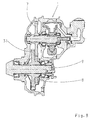
- a hydraulic radial piston engine 1 with a crankshaft 2 with an eccentric portion 3 has a cylinder 4, which is mounted on the one hand in the third housing part 5 and the second housing part 6.
- the crankshaft 2 is rotatably connected to a first spur gear 7.
- the first spur gear 7 is in operative connection with a second spur gear 8, which drives an output shaft 9. If the output shaft 9 has a sprocket 10 and an output flange 11, it is possible to grow the hydrostatic-mechanical gear directly to a drive axle, and it exists but also the ability to auzurüsten the output shaft 9 on each side with a driven flange 11 to arrange the hydrostatic-mechanical transmission between the drive axles.
- the first spur gear 7 and the second spur gear 8 are helical teeth.
- the crankshaft 2 is mounted via a first bearing 12, a second bearing 13 and a third bearing 14.
- the first bearing 12 is arranged in the first housing part 15 and forms the first bearing point.
- the second bearing 13 is arranged between the spur gear 7 and the eccentric portion 3 in the second housing part 6 and forms the second bearing point.
- the second housing part 6 has for this purpose a housing wall 16.
- the third bearing 14 is arranged in the third housing part 5 and forms the third bearing point.
- the crankshaft 2 drives a pressure medium distributor 18 via a connecting shaft 17, which may also be formed integrally with the crankshaft 2.
- the pressure medium distributor 18 is arranged in a valve housing 19, in which additionally the required valves and the main connections for the pressure medium supply 20 are arranged.
- the first housing part 15 forms with the second housing part 6 a lubricant space 21, which in relation to the space 22 via a seal 23 pressure fluid tight is sealed.
- the valves in the valve housing 19 and the leakage of the radial piston motor 1 flow into the space 22 and are directed from there via a line, not shown, via a cooler into an external lubricant reservoir.
- the cylinder 4 has bearing pins 24, via which the cylinder 4 is rotatably mounted and which are in operative connection with a rotation angle sensor, not shown, whereby the displacement of the hydraulic motor can be determined.
- This signal serves as a controlled variable to regulate the displacement of the hydraulic motor accordingly.
- the second spur gear 8 is shielded by a shield 25 in order to reduce the splintering losses when the second spur gear 8 is rotating.
- the shield 25 is preferably designed in two parts, and it is possible to produce the two components from a plastic, for example a polyamide.
- the shield 25 has at least one elevation 26, which engages in a recess 27 in order to fix the position of the shield 25.
- the two individual parts of the shield 25 are plugged together in the axial direction and abut on the first housing part 15 and the second housing part 6 in the axial direction, whereby the shield 25 remains closed.
- the bearing pins 24 have not shown, extending in the axial direction surfaces, which prevent hydraulic pressure is built up between the blind hole in the second housing part 6 or in the third housing part 5 and the bearing pin 24, which presses apart the second housing part 6 and the third housing part 5 ,
- the radial piston engine 1 has a crankshaft 2 whose eccentric portion 3 moves pistons 28 in the cylinders 4.
- the hydrostatic-mechanical transmission according to FIG. 3 differs from the hydrostatic-mechanical transmission according to FIG. 1 in that two radial piston motors are present, each radial piston motor driving a spur gear which is in operative connection with spur gears arranged on an output shaft 9.
- the first radial piston motor 1 drives the first spur gear 7, which is in operative connection with the second spur gear 8 and drives the output shaft 9.
- the second, not shown, radial piston motor 29 drives a third spur gear 30, not shown, which is in operative connection with the fourth spur gear 31, which drives the output shaft 9.
- the first radial piston motor 1 and the second radial piston motor 29 are in operative connection with the output shaft 9.
- the second radial piston motor 29 drives via the third spur gear 30, the fourth spur gear 31 and thereby the output shaft 9 at.
- the first spur gear 7 and the second spur gear 8 are arranged.
- the space 22 of the radial piston motor 1 and the displacement adjusting device 32 are arranged.
- the valve housing 19 In the valve housing 19, the 4/2-proportional valve 33 for adjusting the stroke volume, the shuttle valve 34 and the purge valve 35 are arranged with the associated pressure relief valve 36. Ebeno, the valve housing 19, the connections 20 for the main pressure medium supply. The venting of the valves in the valve housing 19 is passed via the lines 37 into the space 22 and from there via the line 38 and the radiator 39 in a pressure medium reservoir 40.
- the radial piston motor 1 is sufficiently cooled and the hydrostatic-mechanical drive has only a small Number of ports on.
- the first radial piston motor 1 with its displacement adjusting device 32 and the second radial piston motor 29 with its displacement adjusting device 41 are located in the space 22 and the spur gears 7, 8, 30 and 31 are located 21.
- the valve housing 19 also has a shut-off valve 42 , by means of which the first radial piston motor 1 can be completely connected to the space 22, whereby the radial piston motor 1, when it is adjusted to its displacement zero, can be operated at very high speed, since it is completely separated from the high-pressure supply on the one hand and by the Connection with the room 22 can dissipate heat loss. As a result, it is no longer necessary to arrange a shut-off clutch between the first radial piston motor 1 and the first spur gear 7.
Landscapes
- Engineering & Computer Science (AREA)
- General Engineering & Computer Science (AREA)
- Mechanical Engineering (AREA)
- Hydraulic Motors (AREA)
- Braking Arrangements (AREA)
- Crystals, And After-Treatments Of Crystals (AREA)
Abstract
Description
- Die Erfindung bezieht sich auf ein hydrostatisch-mechanisches Getriebe nach der im Oberbegriff von Anspruch 1 näher definierten Art.
- Die
DE 10 2004 023 631 A1 offenbart ein hydrostatisch-mechanisches Getriebe mit einem Radialkolbenmotor mit einer Kurbelwelle, wobei die Kurbelwelle ein Stirnrad antreibt, welches mit einem weiteren Stirnrad in Wirkverbindung ist und den Abtrieb antreibt. - Gattungsgemäße Getriebe werden beispielsweise in Arbeitsmaschinen, wie Radlader, verwendet.
- Der vorliegenden Erfindung liegt die Aufgabe zugrunde, ein hydrostatisch-mechanisches Getriebe zu schaffen, welches kompakt aufgebaut und betriebssicher ausgeführt ist.
- Erfindungsgemäß, weist das hydrostatisch-mechanische Getriebe mindestens einen Radialkolbenmotor auf, welcher eine Kurbelwelle aufweist, welche ein Stirnrad antreibt. Das Getriebegehäuse besteht aus drei Getriebegehäuseteilen, welche mindestens zwei Räume bilden, wobei in einem ersten Raum, welcher von einem ersten und einem zweiten Gehäuseteil gebildet wird, das Stirnradgetriebe angeordnet ist, und in einem zweiten Raum, welcher durch das zweite und das dritte Getriebegehäuseteil gebildet wird, der Radialkolbenmotor angeordnet ist. Insbesondere sind die Zylinder des Radialkolbenmotors im zweiten und dritten Gehäuseteil gelagert. Dadurch ist es möglich, an das dritte Gehäuseteil ein Ventilgehäuse anzubringen, in welchem die Ventile sowie die Druckmittelzuführungen für den Radialkolbenmotor vorhanden sind. Dadurch, dass das zweite Gehäuseteil den ersten Raum vom zweiten Raum trennt, besteht die Möglichkeit, den ersten Raum druckflüssigkeitsdicht zum zweiten Raum abzudichten, wodurch beispielsweise das Stirnradgetriebe mit einem anderen Schmiermittel versorgt werden kann als der Radialkolbenmotor.
- Des weiteren besteht die Möglichkeit, die Leckage des Radialkolbenmotors in den zweiten Raum abzuführen, welcher beispielsweise über Leitungen mit einem Kühler verbunden sein kann und das Leckageöl über den Kühler in ein Druckmittelreservoir leitet.
- In einer weiteren Ausgestaltungsform ist im Ventilgehäuse ein Spülventil angeordnet, welches heißes Druckmittel des Radialkolbenmotors in den zweiten Raum leitet, über welchen, nach Vermischung mit der Leckage, das Druckmittel und das Leckageöl über den Kühler abgeführt werden. Durch diese Anordnung ist es möglich, ein sehr kompaktes hydrostatisch-mechanisches Getriebe zu schaffen, welches mit unterschiedlichen Schmiermitteln betrieben werden kann und bei welchem auf einfache Weise der Radialkolbenmotor vor Überhitzung geschützt ist.
- Vorzugsweise ist die Kurbelwelle über drei Lagerstellen gelagert, wodurch die Kurbelwelle so dimensioniert werden kann, dass bei der maximal zulässigen Durchbiegung der zur Verfügung stehende Bauraum eingehalten werden kann. Vorzugsweise ist eine Lagerstelle zwischen dem Stirnrad und dem exzentrischen Teil der Kurbelwelle und die beiden anderen Lagerstellen jeweils im Bereich der Enden der Kurbelwelle angeordnet.
- In einer weiteren Ausgestaltungsform der Erfindung ist das Stirnrad schrägverzahnt ausgeführt und die beiden benachbart zum exzentrischen Teil der Kurbelwelle angeordneten Lager sind als Kegelrollenlager ausgeführt, wodurch das Kegelrollenlager, welches im Bereich der Druckmittelzuführung zu den Zylindern angeordnet ist, eine Axialkraftkomponente erzeugt, welche der hydraulischen Kraft im Bereich des Druckmittelverteilers entgegenwirkt, wodurch die Verformung des Gehäuseteils, in welchem die Druckmittelzuführungen angeordnet sind, reduziert werden. Indem das Stirnrad beidseitige Lagerstellen aufweist, wird die Radialkraft, welche durch das Zusammenwirken der Stirnräder erzeugt wird, direkt in das Getriebegehäuse eingeleitet, wodurch die Durchbiegung der Kurbelwelle zusätzlich verringert wird. Da der Druckmittelverteiler über eine Verbindungswelle mit der Kurbelwelle verbunden ist, wird durch die Reduzierung der Durchbiegung der Kurbelwelle auch die Radialbewegung des Druckmittelverteilers reduziert.
- In einer weiteren Ausgestaltungsform der Erfindung besteht das Getriebegehäuse aus drei Getriebegehäuseteilen mit Lagerstellen:
- einem ersten Gehäuseteil, in welchem die Stirnräder sowie die erste Lagerstelle im Bereich des Stirnrads angeordnet ist,
- einem zweiten Gehäuseteil, welches die mittlere Lagerstelle zwischen dem Stirnrad und dem exzentrischen Teil der Kurbelwelle bildet und
- einem dritten Gehäuseteil, welches die dritte Lagerstelle aufnimmt und die Druckmittelzuführungen beinhaltet.
- An das dritte Gehäuseteil schließt ein Ventilgehäuse an, welches die Druckmittelverteilung sowie die Druckmittelanschlüsse und weitere Ventile beinhaltet, wodurch dieser Aufbau ermöglicht, dass das erste und zweite Gehäuseteil einen Schmiermittelraum schaffen, in welchem die Stirnräder angeordnet sind, das zweite und dritte Gehäuseteil einen Schmiermittelraum schaffen, in welchem die Hauptbauteile des Radialkolbenmotors angeordnet sind und das Ventilgehäuse die Ventilbauteile aufnimmt.
- Vorzugsweise sind der Schmiermittelraum, in welchem sich die Stirnräder befinden, und der Schmiermittelraum, in welchem sich der Radialkolbenmotor befindet, flüssigkeitsdicht gegeneinander abgedichtet.
- In einer weiteren Ausgestaltungsform treibt das mit der Kurbelwelle in Wirkverbindung stehende Stirnrad ein weiteres Stirnrad an, welches den Abtrieb antreibt, welcher entweder zwei Abtriebsflansche, jeweils an den Enden der Abtriebswelle, oder einen Abtriebsflansch und ein Kegelritzel aufweist, um das hydrostatisch-mechanische Getriebe entweder zwischen der Vorderachse und der Hinterachse des Fahrzeugs einzubauen, um die Vorderachse und die Hinterachse anzutreiben oder direkt an die Hinterachse einzubauen, um die Vorderachse und die Hinterachse anzutreiben oder direkt an die Hinterachse einzubauen, um über den verbleibenden Abtriebsflansch die andere Achse über eine Kardanwelle anzutreiben.
- Weitere Merkmale sind der Figuren-Beschreibung zu entnehmen.
Es zeigen: - Fig. 1
- einen Schnitt durch das hydrostatisch-mechanische Getriebe mit einem Radialkolbenmotor;
- Fig. 2
- einen Schnitt durch den Radialkolbenmotor des hydrostatisch-mechanischen Getriebes nach Fig. 1;
- Fig. 3
- einen Schnitt durch ein hydrostatisch-mechanisches Getriebe mit zwei Radialkolbenmotoren;
- Fig. 4
- einen Schnitt durch die Radialkolbenmotoren des hydrostatisch-mechanischen Getriebes nach Fig. 3;
- Fig. 5
- einen Schnitt durch den anderen Radialkolbenmotor des hydrostatisch-mechanischen Getriebes nach Fig. 3;
- Fig. 6
- ein Hydraulikschema des hydrostatisch-mechanischen Getriebes nach Fig. 1 und
- Fig. 7
- ein Hydraulikschema des hydrostatisch-mechanischen Getriebes nach Fig. 3.
- Ein hydraulischer Radialkolbenmotor 1 mit einer Kurbelwelle 2 mit einem exzentrischen Abschnitt 3 weist einen Zylinder 4 auf, welcher einerseits in dem dritten Gehäuseteil 5 und dem zweiten Gehäuseteil 6 gelagert ist. Die Kurbelwelle 2 ist mit einem ersten Stirnrad 7 drehfest verbunden. Das erste Stirnrad 7 steht in Wirkverbindung mit einem zweiten Stirnrad 8, welches eine Abtriebswelle 9 antreibt Weist die Abtriebswelle 9 ein Ritzel 10 und einen Abtriebsflansch 11 auf, so besteht die Möglichkeit, das hydrostatisch-mechanische Getriebe direkt an eine Antriebsachse anzubauen, und es besteht aber auch die Möglichkeit, die Abtriebswelle 9 auf jeder Seite mit einem Abtriebsflansch 11 auzurüsten, um das hydrostatisch-mechanische Getriebe zwischen den Antriebsachsen anzuordnen.
- Vorzugsweise sind das erste Stirnrad 7 und das zweite Stirnrad 8 schrägverzahnt ausgeführt. Die Kurbelwelle 2 ist über eine erste Lagerung 12, eine zweite Lagerung 13 und eine dritte Lagerung 14 gelagert. Die erste Lagerung 12 ist in dem ersten Gehäuseteil 15 angeordnet und bildet die erste Lagerstelle. Die zweite Lagerung 13 ist zwischen dem Stirnrad 7 und dem exzentrischen Abschnitt 3 im zweiten Gehäuseteil 6 angeordnet und bildet die zweite Lagerstelle. Das zweite Gehäuseteil 6 weist hierfür eine Gehäusewand 16 auf. Die dritte Lagerung 14 ist in dem dritten Gehäuseteil 5 angeordnet und bildet die dritte Lagerstelle. Die Kurbelwelle 2 treibt über eine Verbindungswelle 17, welche auch einstückig mit der Kurbelwelle 2 ausgebildet sein kann, einen Druckmittelverteiler 18 an. Durch die spezielle Lagerung der Kurbelwelle wird die Durchbiegung der Kurbelwelle 2 verringert, wodurch sich auch die Funktion des Druckmittelverteilers 18 verbessert. Der Druckmittelverteiler 18 ist in einem Ventilgehäuse 19 angeordnet, in welchem zusätzlich die benötigten Ventile und die Hauptanschlüsse für die Druckmittelversorgung 20 angeordnet sind. Das erste Gehäuseteil 15 bildet mit dem zweiten Gehäuseteil 6 einen Schmiermittelraum 21, welcher gegenüber dem Raum 22 über eine Dichtung 23 druckflüssigkeitsdicht abgedichtet ist. Somit besteht die Möglichkeit, unterschiedliche Schmiermittel für den Raum 21 und den Raum 22 zu verwenden. Die Ventile im Ventilgehäuse 19 sowie die Leckage des Radialkolbenmotors 1 fließen in den Raum 22 und werden von dort über eine nicht gezeigte Leitung über einen Kühler in ein externes Schmierflüssigkeitsreservoir geleitet. Der Zylinder 4 weist Lagerzapfen 24 auf, über welche der Zylinder 4 drehbar gelagert ist und welche mit einem nicht gezeigten Drehwinkelsensor in Wirkverbindung stehen, wodurch das Schluckvolumen des hydraulischen Motors ermittelt werden kann. Dieses Signal dient als Regelgröße, um das Schluckvolumen des Hydromotors entsprechend einzuregeln. Das zweite Stirnrad 8 ist durch eine Abschirmung 25 abgeschirmt, um die Panschverluste bei drehendem zweitem Stirnrad 8 zu verringern. Die Abschirmung 25 ist vorzugsweise zweiteilig ausgeführt, und es besteht die Möglichkeit, die beiden Bauteile aus einem Kunststoff, beispielsweise einem Polyamid, herzustellen. Die Abschirmung 25 weist mindestens eine Erhebung 26 auf, welche in eine Ausnehmung 27 eingreift, um die Position der Abschirmung 25 zu fixieren. Die beiden einzelnen Teile der Abschirmung 25 sind in axialer Richtung zusammengesteckt und liegen an dem ersten Gehäuseteil 15 und dem zweiten Gehäuseteil 6 in axialer Richtung an, wodurch die Abschirmung 25 geschlossen bleibt. Die Lagerzapfen 24 weisen nicht gezeigte, in axialer Richtung verlaufende Flächen auf, welche verhindern, dass zwischen der Sacklochbohrung im zweiten Gehäuseteil 6 oder im dritten Gehäuseteil 5 und dem Lagerzapfen 24 hydraulischer Druck aufgebaut wird, welcher das zweite Gehäuseteil 6 und das dritte Gehäuseteil 5 auseinanderdrückt.
- Der Radialkolbenmotor 1 weist eine Kurbelwelle 2 auf, deren exzentrischer Abschnitt 3 Kolben 28 in den Zylindern 4 bewegt.
- Das hydrostatisch-mechanische Getriebe nach Fig. 3 unterscheidet sich vom hydrostatisch-mechanischen Getriebe nach Fig. 1 dadurch, dass zwei Radialkolbenmotore vorhanden sind, wobei jeder Radialkolbenmotor ein Stirnrad antreibt, welches mit auf einer Abtriebswelle 9 angeordneten Stirnrädern in Wirkverbindung steht. Der erste Radialkolbenmotor 1 treibt das erste Stirnrad 7 an, welches mit dem zweiten Stirnrad 8 in Wirkverbindung steht und die Abtriebswelle 9 antreibt. Der zweite, nicht gezeigte Radialkolbenmotor 29 treibt ein nicht gezeigtes drittes Stirnrad 30 an, welches mit dem vierten Stirnrad 31 in Wirkverbindung steht, welches die Abtriebswelle 9 antreibt.
- Der erste Radialkolbenmotor 1 und der zweite Radialkolbenmotor 29 sind in Wirkverbindung mit der Abtriebswelle 9.
- Der zweite Radialkolbenmotor 29 treibt über das dritte Stirnrad 30 das vierte Stirnrad 31 und dadurch die Abtriebswelle 9 an.
- Im Raum 21 sind das erste Stirnrad 7 und das zweite Stirnrad 8 angeordnet. Im Raum 22 sind der Radialkolbenmotor 1 sowie dessen Hubraum-Verstelleinrichtung 32 angeordnet. Im Ventilgehäuse 19 sind das 4/2-Proportionalventil 33 zur Verstellung des Hubvolumens, das Wechselventil 34 und das Spülventil 35 mit dem dazugehörigen Druckbegrenzungsventil 36 angeordnet. Ebeno weist das Ventilgehäuse 19 die Anschlüsse 20 für die Hauptdruckmittelversorgung auf. Die Entlüftung der Ventile im Ventilgehäuse 19 wird über die Leitungen 37 in den Raum 22 geleitet und von dort über die Leitung 38 und den Kühler 39 in ein Druckmittelreservoir 40. Somit wird der Radialkolbenmotor 1 ausreichend gekühlt und der hydrostatisch-mechanische Antrieb weist nur eine geringe Anzahl von Anschlüssen auf.
- Der erste Radialkolbenmotor 1 mit seiner Hubraum-Verstelleinrichtung 32 und der zweite Radialkolbenmotor 29 mit seiner Hubraum-Verstelleinrichtung 41 befinden sich im Raum 22 und die Stirnräder 7, 8, 30 und 31 befinden sich Raum 21. Das Ventilgehäuse 19 weist zusätzlich ein Abschaltventil 42 auf, mittels welchem der erste Radialkolbenmotor 1 vollständig mit dem Raum 22 verbunden werden kann, wodurch der Radialkolbenmotor 1, wenn er auf sein Hubvolumen Null verstellt ist, bei sehr hoher Drehzahl betrieben werden kann, da er einerseits vollständig von der Hochdruckzuführung getrennt ist und durch die Verbindung mit dem Raum 22 Wärmeverluste abführen kann. Dadurch ist es nicht mehr notwendig, eine Abschaltkupplung zwischen dem ersten Radialkolbenmotor 1 und dem ersten Stirnrad 7 anzuordnen.
-
- 1
- Radialkolbenmotor
- 2
- Kurbelwelle
- 3
- exzentrischer Abschnitt
- 4
- Zylinder
- 5
- drittes Gehäuseteil
- 6
- zweites Gehäuseteil
- 7
- erstes Stirnrad
- 8
- zweites Stirnrad
- 9
- Abtriebswelle
- 10
- Ritzel
- 11
- Abtriebsflansch
- 12
- erste Lagerung
- 13
- zweite Lagerung
- 14
- dritte Lagerung
- 15
- erstes Gehäuseteil
- 16
- Gehäusewand
- 17
- Verbindungswelle
- 18
- Druckmittelverteiler
- 19
- Ventilgehäuse
- 20
- Anschlüsse
- 21
- Raum
- 22
- Raum
- 23
- Dichtung
- 24
- Lagerzapfen
- 25
- Abschirmung
- 26
- Erhebung
- 27
- Ausnehmung
- 28
- Kolben
- 29
- zweiter Radialkolbenmotor
- 30
- drittes Stirnrad
- 31
- viertes Stirnrad
- 32
- Hubraum-Verstelleinrichtung
- 33
- 4/2-Proportionalventil
- 34
- Wechselventil
- 35
- Spülventil
- 36
- Druckbegrenzungsventil
- 37
- Leitung
- 38
- Leitung
- 39
- Kühler
- 40
- Druckmittelreservoir
- 41
- Hubraum-Verstelleinrichtung
- 42
- Abschaltventil
Claims (5)
- Hydrostatisch-mechanisches Getriebe mit einem Radialkolbenmotor (1) mit einer Kurbelwelle (2) und Zylindern (4), welcher über mindestens ein Stirnradgetriebe (7, 8) einen Abtrieb antreibt, wobei das Stirnradgetriebe (7, 8) und der Radialkolbenmotor (7) in einem Getriebegehäuse angeordnet sind, dadurch gekennzeichnet, dass das Getriebegehäuse aus mindestens drei Gehäuseteilen (5, 6, 15) besteht, wobei ein erstes Gehäuseteil (15) und ein zweites Gehäuseteil (6) einen Raum (21) bilden, in welchem das Stirnradgetriebe (7, 8) angeordnet ist, und die Zylinder (4) einerseits in dem zweiten Gehäuseteil (6) und einem dritten Gehäuseteil (5) gelagert sind, wobei das zweite Gehäuseteil (6) und das dritte Gehäuseteil (5) einen Raum (22) bilden, in welchem der Radialkolbenmotor (1) angeordnet ist, und sich das zweite Gehäuseteil (6) benachbart zum Stirnradgetriebe (7, 8) und zum Radialkolbenmotor (1) befindet.
- Hydrostatisch-mechanisches Getriebe nach Anspruch 1, dadurch gekennzeichnet, dass das dritte Gehäuseteil (5) mit einem Ventilgehäuse (19) verbunden ist, über welches der Radialkolbenmotor (1) mit Druckmittel versorgt wird.
- Hydrostatisch-mechanisches Getriebe nach Anspruch 1, dadurch gekennzeichnet, dass die Leckage des Radialkolbenmotors (1) in den vom zweiten Gehäuseteil (6) und dritten Gehäuseteil (5) gebildeten Raum (22) fließt, von welchem dieses über einen Kühler (39) in ein Druckmittelreservoir (40) fließt.
- Hydrostatisch-mechanisches Getriebe nach Anspruch 2, dadurch gekennzeichnet, dass im Ventilgehäuse (19) ein Spülventil (35) angeordnet ist, über welches Druckmittel aus einer Druckmittelrückführung vom Radialkolbenmotor in den Raum (22), welchen die zweite Gehäusehälfte (6) und die dritte Gehäusehälfte (5) bilden, gelangt
- Hydrostatisch-mechanisches Getriebe nach Anspruch 1, dadurch gekennzeichnet, dass der Raum (21), welchen die erste Gehäusehälfte (15) und die zweite Gehäusehälfte (6) bilden, druckflüssigkeitsdicht gegen den Raum (22), welchen die zweite Gehäusehälfte (6) und die dritte Gehäusehälfte (5) bilden, abgedichtet ist.
Applications Claiming Priority (1)
| Application Number | Priority Date | Filing Date | Title |
|---|---|---|---|
| DE102006043289A DE102006043289A1 (de) | 2006-09-14 | 2006-09-14 | Hydrostatisch-mechanisches Getriebe |
Publications (2)
| Publication Number | Publication Date |
|---|---|
| EP1900971A1 true EP1900971A1 (de) | 2008-03-19 |
| EP1900971B1 EP1900971B1 (de) | 2009-11-04 |
Family
ID=38657749
Family Applications (1)
| Application Number | Title | Priority Date | Filing Date |
|---|---|---|---|
| EP07115497A Not-in-force EP1900971B1 (de) | 2006-09-14 | 2007-09-03 | Hydrostatisch-mechanisches Getriebe |
Country Status (4)
| Country | Link |
|---|---|
| US (1) | US7814813B2 (de) |
| EP (1) | EP1900971B1 (de) |
| AT (1) | ATE447683T1 (de) |
| DE (2) | DE102006043289A1 (de) |
Cited By (3)
| Publication number | Priority date | Publication date | Assignee | Title |
|---|---|---|---|---|
| DE102010001976A1 (de) | 2010-02-16 | 2011-08-18 | ZF Friedrichshafen AG, 88046 | Hydraulikanordnung zum Ansteuern von hydrostatischen Motoren |
| EP2955419A1 (de) * | 2014-06-10 | 2015-12-16 | Deere & Company | Hydraulisches spülsystem und verfahren |
| DE102015225747A1 (de) | 2015-12-17 | 2017-06-22 | Zf Friedrichshafen Ag | Verfahren zum Betreiben eines hydrostatischen Fahrantriebs und hydrostatischer Fahrantrieb |
Families Citing this family (4)
| Publication number | Priority date | Publication date | Assignee | Title |
|---|---|---|---|---|
| DE102013202385A1 (de) | 2013-02-14 | 2014-08-14 | Zf Friedrichshafen Ag | Verfahren zur Steuerung eines hydrostatischen Getriebes |
| CN111195976A (zh) * | 2020-02-17 | 2020-05-26 | 徐州工润建筑科技有限公司 | 一种拼接式pc叠合楼梯模具 |
| TWI750884B (zh) * | 2020-11-04 | 2021-12-21 | 朝程工業股份有限公司 | 電動工具 |
| DE102021205220A1 (de) | 2021-05-21 | 2022-11-24 | Zf Friedrichshafen Ag | Ummantelungsvorrichtung |
Citations (10)
| Publication number | Priority date | Publication date | Assignee | Title |
|---|---|---|---|---|
| US3902567A (en) * | 1974-04-03 | 1975-09-02 | Mack Trucks | Noise attenuating transmission casing |
| US5078659A (en) * | 1989-12-11 | 1992-01-07 | Unipat Ag | Variable speed transaxle |
| EP0483543A1 (de) * | 1990-10-31 | 1992-05-06 | Liebherr-Werk Bischofshofen GmbH | Hydrostatischer Antrieb, vorzugsweise für ein Erdbewegungsfahrzeug, beispielsweise Radlader |
| WO1999017021A1 (en) * | 1997-09-29 | 1999-04-08 | S.A.I. Societa' Apparecchiature Idrauliche S.P.A. | Hydraulic machine with radial pistons and variable displacement |
| EP1148275A1 (de) * | 2000-04-19 | 2001-10-24 | Dana Italia S.p.A | Nutzfahrzeug Getriebe mit zwei steuerbaren hydrostatischen Motoren |
| US6321867B1 (en) * | 1998-11-05 | 2001-11-27 | New Holland North America, Inc. | Charge flow supplement circuit for tractors |
| US6354975B1 (en) * | 2000-08-18 | 2002-03-12 | Hydro-Thoma Limited | Combined hydrostatic and gear transmissions employing independent sumps |
| US6953327B1 (en) * | 2003-03-11 | 2005-10-11 | Hydro-Gear Limited Partnership | Dual pump |
| WO2005111475A1 (de) * | 2004-05-10 | 2005-11-24 | Zf Friedrichshafen Ag | Antrieb für ein mobilfahrzeug |
| WO2005111466A1 (de) * | 2004-05-10 | 2005-11-24 | Zf Friedrichshafen Ag | Antrieb für mobilfahrzeuge |
Family Cites Families (16)
| Publication number | Priority date | Publication date | Assignee | Title |
|---|---|---|---|---|
| US2683422A (en) * | 1950-05-19 | 1954-07-13 | Jr Albert Z Richards | Rotary engine or compressor |
| DE1261761B (de) | 1959-06-04 | 1968-02-22 | Eric George Kimsey | Einrichtung zum Abstuetzen und Abdichten des Abstuetzkoerpers gegenueber den Boeden der Hohlkolben eines Radialkolbenmotors |
| US3199460A (en) * | 1962-01-11 | 1965-08-10 | Stewart Warner Corp | Hydraulic pump or motor |
| DE2222411A1 (de) * | 1972-05-06 | 1973-11-15 | Agfa Gevaert Ag | Makro-zoom-objektiv |
| DE3441966A1 (de) | 1984-11-16 | 1986-05-28 | G. Düsterloh GmbH, 4322 Sprockhövel | Steuerung fuer einen hydrostatischen kolbenmotor |
| US4843818A (en) * | 1986-08-29 | 1989-07-04 | Thoma Christian H | Rotary hydrostatic machines or transmissions |
| US5042252A (en) * | 1990-02-22 | 1991-08-27 | Unipat Ag | Neutral shifting mechanism for hydrostatic transmission |
| US5177967A (en) * | 1991-07-22 | 1993-01-12 | Tecumseh Products Company | Hydrostatic transaxle |
| US5239827A (en) * | 1991-12-27 | 1993-08-31 | Tecumseh Products Company | Hydrostatic track ring snubber |
| US5400594A (en) * | 1992-09-04 | 1995-03-28 | Tecumseh Products Company | Slipper guide for a hydrostatic transmission |
| US5392603A (en) * | 1993-03-01 | 1995-02-28 | Tecumseh Products Company | Bevel gear load balance in a hydrostatic transmission |
| DE19612309B4 (de) * | 1996-03-28 | 2005-11-17 | Zf Friedrichshafen Ag | Antriebsvorrichtung für eine Mischtrommel |
| SE506582C2 (sv) * | 1996-04-03 | 1998-01-12 | Kesol Production Ab | Anordning vid en radialkolvmotor av rotationstyp |
| US5992150A (en) * | 1996-12-23 | 1999-11-30 | Tecumseh Products Company | Transaxle with hydrostatic transmission |
| DE102004038506A1 (de) * | 2004-08-07 | 2006-02-23 | Zf Friedrichshafen Ag | Getriebe, insbesondere zum Antrieb einer Trommel eines Fahrmischers |
| DE102004048174A1 (de) | 2004-10-02 | 2006-04-06 | Zf Friedrichshafen Ag | Einrichtung zur Bestimmung des Schluckvolumens eines verstellbaren Radialkolbenmotors |
-
2006
- 2006-09-14 DE DE102006043289A patent/DE102006043289A1/de not_active Withdrawn
-
2007
- 2007-09-03 AT AT07115497T patent/ATE447683T1/de active
- 2007-09-03 EP EP07115497A patent/EP1900971B1/de not_active Not-in-force
- 2007-09-03 DE DE502007001889T patent/DE502007001889D1/de active Active
- 2007-09-13 US US11/854,642 patent/US7814813B2/en not_active Expired - Fee Related
Patent Citations (10)
| Publication number | Priority date | Publication date | Assignee | Title |
|---|---|---|---|---|
| US3902567A (en) * | 1974-04-03 | 1975-09-02 | Mack Trucks | Noise attenuating transmission casing |
| US5078659A (en) * | 1989-12-11 | 1992-01-07 | Unipat Ag | Variable speed transaxle |
| EP0483543A1 (de) * | 1990-10-31 | 1992-05-06 | Liebherr-Werk Bischofshofen GmbH | Hydrostatischer Antrieb, vorzugsweise für ein Erdbewegungsfahrzeug, beispielsweise Radlader |
| WO1999017021A1 (en) * | 1997-09-29 | 1999-04-08 | S.A.I. Societa' Apparecchiature Idrauliche S.P.A. | Hydraulic machine with radial pistons and variable displacement |
| US6321867B1 (en) * | 1998-11-05 | 2001-11-27 | New Holland North America, Inc. | Charge flow supplement circuit for tractors |
| EP1148275A1 (de) * | 2000-04-19 | 2001-10-24 | Dana Italia S.p.A | Nutzfahrzeug Getriebe mit zwei steuerbaren hydrostatischen Motoren |
| US6354975B1 (en) * | 2000-08-18 | 2002-03-12 | Hydro-Thoma Limited | Combined hydrostatic and gear transmissions employing independent sumps |
| US6953327B1 (en) * | 2003-03-11 | 2005-10-11 | Hydro-Gear Limited Partnership | Dual pump |
| WO2005111475A1 (de) * | 2004-05-10 | 2005-11-24 | Zf Friedrichshafen Ag | Antrieb für ein mobilfahrzeug |
| WO2005111466A1 (de) * | 2004-05-10 | 2005-11-24 | Zf Friedrichshafen Ag | Antrieb für mobilfahrzeuge |
Cited By (5)
| Publication number | Priority date | Publication date | Assignee | Title |
|---|---|---|---|---|
| DE102010001976A1 (de) | 2010-02-16 | 2011-08-18 | ZF Friedrichshafen AG, 88046 | Hydraulikanordnung zum Ansteuern von hydrostatischen Motoren |
| EP2955419A1 (de) * | 2014-06-10 | 2015-12-16 | Deere & Company | Hydraulisches spülsystem und verfahren |
| US9835186B2 (en) | 2014-06-10 | 2017-12-05 | Deere & Company | Hydraulic flushing system and method |
| RU2674858C2 (ru) * | 2014-06-10 | 2018-12-13 | Дир Энд Компани | Система и способ гидравлической промывки |
| DE102015225747A1 (de) | 2015-12-17 | 2017-06-22 | Zf Friedrichshafen Ag | Verfahren zum Betreiben eines hydrostatischen Fahrantriebs und hydrostatischer Fahrantrieb |
Also Published As
| Publication number | Publication date |
|---|---|
| EP1900971B1 (de) | 2009-11-04 |
| DE102006043289A1 (de) | 2008-03-27 |
| DE502007001889D1 (de) | 2009-12-17 |
| ATE447683T1 (de) | 2009-11-15 |
| US20080070735A1 (en) | 2008-03-20 |
| US7814813B2 (en) | 2010-10-19 |
Similar Documents
| Publication | Publication Date | Title |
|---|---|---|
| DE4238256C2 (de) | Zapfenwellengetriebe mit einer Schmiereinrichtung | |
| EP1900971B1 (de) | Hydrostatisch-mechanisches Getriebe | |
| WO2008064639A1 (de) | Kombination aus einer dichtungsscheibe und einer blattfeder-mitnehmerscheibe | |
| DE102008053318A1 (de) | Reversibel betreibbare Zahnradmaschine, sowie Fahrzeuglenksystem und Verfahren zur Steuerung eines Fahrzeuglenksystems | |
| DE3440219A1 (de) | Hydrostatische maschine | |
| EP4185773B1 (de) | Innenzahnradfluidmaschine | |
| DE10314335A1 (de) | Hydrodynamischer Drehmomentwandler | |
| DE102006021570A1 (de) | Hydrostatische Kolbenmaschine mit drehbarer Steuerscheibe | |
| EP1900972B1 (de) | Hydrostatisch-mechanisches Getriebe | |
| DE60304975T2 (de) | Vorrichtung zur Übertagung von Drehmoment zwischen zwei drehbaren, koaxialen Wellen | |
| DE3008869C2 (de) | Arbeitsfahrzeug mit einer Betriebsölkühlleitung zwischen einem Wandlergehäuse und einem Übertragungsgehäuse | |
| DE3607709A1 (de) | Hydrostatische lenkanlage, insbesondere fuer kraftfahrzeuge | |
| DE102012204773B4 (de) | Anordnung zur Ölversorgung eines Anbaumoduls | |
| EP3772159A1 (de) | Elektromechanische antriebseinheit, insbesondere einzelradantriebseinheit | |
| EP1745225B1 (de) | Antrieb für mobilfahrzeuge | |
| DD224907A1 (de) | Hydrostatische tandempumpe | |
| EP1745229B1 (de) | Antrieb für ein mobilfahrzeug | |
| DE3237032A1 (de) | Oelpumpenanordnung, insbesondere fuer getriebe | |
| DE19823508C2 (de) | Mobiles Arbeitsfahrzeug mit kompakter Achsbaugruppe | |
| EP2625427A2 (de) | Strömungsgetriebe | |
| DE102004023628A1 (de) | Hydraulischer Antrieb für Mobilfahrzeuge | |
| DE69616571T2 (de) | Vorrichtung für ein lenkgetriebe | |
| DE102019219048A1 (de) | Kraftfahrzeuggetriebe mit einem Nebenabtrieb | |
| DE102019219046A1 (de) | Kraftfahrzeuggetriebe mit einem Nebenabtrieb | |
| DE102011008362A1 (de) | Zweistufige Druckregelung |
Legal Events
| Date | Code | Title | Description |
|---|---|---|---|
| PUAI | Public reference made under article 153(3) epc to a published international application that has entered the european phase |
Free format text: ORIGINAL CODE: 0009012 |
|
| 17P | Request for examination filed |
Effective date: 20071214 |
|
| AK | Designated contracting states |
Kind code of ref document: A1 Designated state(s): AT BE BG CH CY CZ DE DK EE ES FI FR GB GR HU IE IS IT LI LT LU LV MC MT NL PL PT RO SE SI SK TR |
|
| AX | Request for extension of the european patent |
Extension state: AL BA HR MK YU |
|
| AKX | Designation fees paid |
Designated state(s): AT BE BG CH CY CZ DE DK EE ES FI FR GB GR HU IE IS IT LI LT LU LV MC MT NL PL PT RO SE SI SK TR |
|
| GRAP | Despatch of communication of intention to grant a patent |
Free format text: ORIGINAL CODE: EPIDOSNIGR1 |
|
| GRAS | Grant fee paid |
Free format text: ORIGINAL CODE: EPIDOSNIGR3 |
|
| GRAA | (expected) grant |
Free format text: ORIGINAL CODE: 0009210 |
|
| AK | Designated contracting states |
Kind code of ref document: B1 Designated state(s): AT BE BG CH CY CZ DE DK EE ES FI FR GB GR HU IE IS IT LI LT LU LV MC MT NL PL PT RO SE SI SK TR |
|
| REG | Reference to a national code |
Ref country code: GB Ref legal event code: FG4D Free format text: NOT ENGLISH |
|
| REG | Reference to a national code |
Ref country code: CH Ref legal event code: EP |
|
| REG | Reference to a national code |
Ref country code: IE Ref legal event code: FG4D |
|
| REF | Corresponds to: |
Ref document number: 502007001889 Country of ref document: DE Date of ref document: 20091217 Kind code of ref document: P |
|
| NLV1 | Nl: lapsed or annulled due to failure to fulfill the requirements of art. 29p and 29m of the patents act | ||
| LTIE | Lt: invalidation of european patent or patent extension |
Effective date: 20091104 |
|
| PG25 | Lapsed in a contracting state [announced via postgrant information from national office to epo] |
Ref country code: FI Free format text: LAPSE BECAUSE OF FAILURE TO SUBMIT A TRANSLATION OF THE DESCRIPTION OR TO PAY THE FEE WITHIN THE PRESCRIBED TIME-LIMIT Effective date: 20091104 Ref country code: ES Free format text: LAPSE BECAUSE OF FAILURE TO SUBMIT A TRANSLATION OF THE DESCRIPTION OR TO PAY THE FEE WITHIN THE PRESCRIBED TIME-LIMIT Effective date: 20100215 Ref country code: SE Free format text: LAPSE BECAUSE OF FAILURE TO SUBMIT A TRANSLATION OF THE DESCRIPTION OR TO PAY THE FEE WITHIN THE PRESCRIBED TIME-LIMIT Effective date: 20091104 Ref country code: LT Free format text: LAPSE BECAUSE OF FAILURE TO SUBMIT A TRANSLATION OF THE DESCRIPTION OR TO PAY THE FEE WITHIN THE PRESCRIBED TIME-LIMIT Effective date: 20091104 Ref country code: IS Free format text: LAPSE BECAUSE OF FAILURE TO SUBMIT A TRANSLATION OF THE DESCRIPTION OR TO PAY THE FEE WITHIN THE PRESCRIBED TIME-LIMIT Effective date: 20100304 Ref country code: PT Free format text: LAPSE BECAUSE OF FAILURE TO SUBMIT A TRANSLATION OF THE DESCRIPTION OR TO PAY THE FEE WITHIN THE PRESCRIBED TIME-LIMIT Effective date: 20100304 |
|
| REG | Reference to a national code |
Ref country code: IE Ref legal event code: FD4D |
|
| PG25 | Lapsed in a contracting state [announced via postgrant information from national office to epo] |
Ref country code: CY Free format text: LAPSE BECAUSE OF FAILURE TO SUBMIT A TRANSLATION OF THE DESCRIPTION OR TO PAY THE FEE WITHIN THE PRESCRIBED TIME-LIMIT Effective date: 20091104 Ref country code: PL Free format text: LAPSE BECAUSE OF FAILURE TO SUBMIT A TRANSLATION OF THE DESCRIPTION OR TO PAY THE FEE WITHIN THE PRESCRIBED TIME-LIMIT Effective date: 20091104 Ref country code: SI Free format text: LAPSE BECAUSE OF FAILURE TO SUBMIT A TRANSLATION OF THE DESCRIPTION OR TO PAY THE FEE WITHIN THE PRESCRIBED TIME-LIMIT Effective date: 20091104 Ref country code: LV Free format text: LAPSE BECAUSE OF FAILURE TO SUBMIT A TRANSLATION OF THE DESCRIPTION OR TO PAY THE FEE WITHIN THE PRESCRIBED TIME-LIMIT Effective date: 20091104 |
|
| PG25 | Lapsed in a contracting state [announced via postgrant information from national office to epo] |
Ref country code: RO Free format text: LAPSE BECAUSE OF FAILURE TO SUBMIT A TRANSLATION OF THE DESCRIPTION OR TO PAY THE FEE WITHIN THE PRESCRIBED TIME-LIMIT Effective date: 20091104 Ref country code: BG Free format text: LAPSE BECAUSE OF FAILURE TO SUBMIT A TRANSLATION OF THE DESCRIPTION OR TO PAY THE FEE WITHIN THE PRESCRIBED TIME-LIMIT Effective date: 20100204 Ref country code: DK Free format text: LAPSE BECAUSE OF FAILURE TO SUBMIT A TRANSLATION OF THE DESCRIPTION OR TO PAY THE FEE WITHIN THE PRESCRIBED TIME-LIMIT Effective date: 20091104 Ref country code: IE Free format text: LAPSE BECAUSE OF FAILURE TO SUBMIT A TRANSLATION OF THE DESCRIPTION OR TO PAY THE FEE WITHIN THE PRESCRIBED TIME-LIMIT Effective date: 20091104 Ref country code: EE Free format text: LAPSE BECAUSE OF FAILURE TO SUBMIT A TRANSLATION OF THE DESCRIPTION OR TO PAY THE FEE WITHIN THE PRESCRIBED TIME-LIMIT Effective date: 20091104 |
|
| PG25 | Lapsed in a contracting state [announced via postgrant information from national office to epo] |
Ref country code: SK Free format text: LAPSE BECAUSE OF FAILURE TO SUBMIT A TRANSLATION OF THE DESCRIPTION OR TO PAY THE FEE WITHIN THE PRESCRIBED TIME-LIMIT Effective date: 20091104 Ref country code: CZ Free format text: LAPSE BECAUSE OF FAILURE TO SUBMIT A TRANSLATION OF THE DESCRIPTION OR TO PAY THE FEE WITHIN THE PRESCRIBED TIME-LIMIT Effective date: 20091104 |
|
| PLBE | No opposition filed within time limit |
Free format text: ORIGINAL CODE: 0009261 |
|
| STAA | Information on the status of an ep patent application or granted ep patent |
Free format text: STATUS: NO OPPOSITION FILED WITHIN TIME LIMIT |
|
| 26N | No opposition filed |
Effective date: 20100805 |
|
| PG25 | Lapsed in a contracting state [announced via postgrant information from national office to epo] |
Ref country code: GR Free format text: LAPSE BECAUSE OF FAILURE TO SUBMIT A TRANSLATION OF THE DESCRIPTION OR TO PAY THE FEE WITHIN THE PRESCRIBED TIME-LIMIT Effective date: 20100205 |
|
| BERE | Be: lapsed |
Owner name: ZF FRIEDRICHSHAFEN A.G. Effective date: 20100930 |
|
| PG25 | Lapsed in a contracting state [announced via postgrant information from national office to epo] |
Ref country code: IT Free format text: LAPSE BECAUSE OF FAILURE TO SUBMIT A TRANSLATION OF THE DESCRIPTION OR TO PAY THE FEE WITHIN THE PRESCRIBED TIME-LIMIT Effective date: 20091104 |
|
| PG25 | Lapsed in a contracting state [announced via postgrant information from national office to epo] |
Ref country code: MC Free format text: LAPSE BECAUSE OF NON-PAYMENT OF DUE FEES Effective date: 20100930 |
|
| REG | Reference to a national code |
Ref country code: FR Ref legal event code: ST Effective date: 20110531 |
|
| PG25 | Lapsed in a contracting state [announced via postgrant information from national office to epo] |
Ref country code: BE Free format text: LAPSE BECAUSE OF NON-PAYMENT OF DUE FEES Effective date: 20100930 Ref country code: FR Free format text: LAPSE BECAUSE OF NON-PAYMENT OF DUE FEES Effective date: 20100930 |
|
| PG25 | Lapsed in a contracting state [announced via postgrant information from national office to epo] |
Ref country code: MT Free format text: LAPSE BECAUSE OF FAILURE TO SUBMIT A TRANSLATION OF THE DESCRIPTION OR TO PAY THE FEE WITHIN THE PRESCRIBED TIME-LIMIT Effective date: 20091104 |
|
| REG | Reference to a national code |
Ref country code: CH Ref legal event code: PL |
|
| GBPC | Gb: european patent ceased through non-payment of renewal fee |
Effective date: 20110903 |
|
| PG25 | Lapsed in a contracting state [announced via postgrant information from national office to epo] |
Ref country code: LI Free format text: LAPSE BECAUSE OF NON-PAYMENT OF DUE FEES Effective date: 20110930 Ref country code: CH Free format text: LAPSE BECAUSE OF NON-PAYMENT OF DUE FEES Effective date: 20110930 |
|
| PG25 | Lapsed in a contracting state [announced via postgrant information from national office to epo] |
Ref country code: GB Free format text: LAPSE BECAUSE OF NON-PAYMENT OF DUE FEES Effective date: 20110903 |
|
| PG25 | Lapsed in a contracting state [announced via postgrant information from national office to epo] |
Ref country code: NL Free format text: LAPSE BECAUSE OF FAILURE TO SUBMIT A TRANSLATION OF THE DESCRIPTION OR TO PAY THE FEE WITHIN THE PRESCRIBED TIME-LIMIT Effective date: 20091104 Ref country code: LU Free format text: LAPSE BECAUSE OF NON-PAYMENT OF DUE FEES Effective date: 20100903 Ref country code: HU Free format text: LAPSE BECAUSE OF FAILURE TO SUBMIT A TRANSLATION OF THE DESCRIPTION OR TO PAY THE FEE WITHIN THE PRESCRIBED TIME-LIMIT Effective date: 20100505 |
|
| PG25 | Lapsed in a contracting state [announced via postgrant information from national office to epo] |
Ref country code: TR Free format text: LAPSE BECAUSE OF FAILURE TO SUBMIT A TRANSLATION OF THE DESCRIPTION OR TO PAY THE FEE WITHIN THE PRESCRIBED TIME-LIMIT Effective date: 20091104 |
|
| REG | Reference to a national code |
Ref country code: AT Ref legal event code: MM01 Ref document number: 447683 Country of ref document: AT Kind code of ref document: T Effective date: 20120903 |
|
| PG25 | Lapsed in a contracting state [announced via postgrant information from national office to epo] |
Ref country code: AT Free format text: LAPSE BECAUSE OF NON-PAYMENT OF DUE FEES Effective date: 20120903 |
|
| PGFP | Annual fee paid to national office [announced via postgrant information from national office to epo] |
Ref country code: DE Payment date: 20200819 Year of fee payment: 14 |
|
| REG | Reference to a national code |
Ref country code: DE Ref legal event code: R119 Ref document number: 502007001889 Country of ref document: DE |
|
| PG25 | Lapsed in a contracting state [announced via postgrant information from national office to epo] |
Ref country code: DE Free format text: LAPSE BECAUSE OF NON-PAYMENT OF DUE FEES Effective date: 20220401 |