EP1900663A2 - Winding machine - Google Patents
Winding machine Download PDFInfo
- Publication number
- EP1900663A2 EP1900663A2 EP07116417A EP07116417A EP1900663A2 EP 1900663 A2 EP1900663 A2 EP 1900663A2 EP 07116417 A EP07116417 A EP 07116417A EP 07116417 A EP07116417 A EP 07116417A EP 1900663 A2 EP1900663 A2 EP 1900663A2
- Authority
- EP
- European Patent Office
- Prior art keywords
- winding
- roll
- roller
- spring
- winding machine
- Prior art date
- Legal status (The legal status is an assumption and is not a legal conclusion. Google has not performed a legal analysis and makes no representation as to the accuracy of the status listed.)
- Granted
Links
- 238000004804 winding Methods 0.000 title claims abstract description 110
- 238000000034 method Methods 0.000 claims abstract description 9
- 239000000463 material Substances 0.000 claims abstract description 8
- 238000013016 damping Methods 0.000 claims description 25
- 238000005452 bending Methods 0.000 claims description 12
- 230000010355 oscillation Effects 0.000 claims description 3
- 230000003044 adaptive effect Effects 0.000 claims description 2
- 239000012530 fluid Substances 0.000 claims description 2
- 238000005096 rolling process Methods 0.000 abstract description 2
- 239000000725 suspension Substances 0.000 description 4
- 240000005860 Portulaca grandiflora Species 0.000 description 3
- 230000000694 effects Effects 0.000 description 3
- 210000003746 feather Anatomy 0.000 description 3
- 241001295925 Gegenes Species 0.000 description 2
- 238000013461 design Methods 0.000 description 2
- 229920001131 Pulp (paper) Polymers 0.000 description 1
- 230000001154 acute effect Effects 0.000 description 1
- 238000003490 calendering Methods 0.000 description 1
- 238000010276 construction Methods 0.000 description 1
- 230000003247 decreasing effect Effects 0.000 description 1
- 238000011161 development Methods 0.000 description 1
- 230000018109 developmental process Effects 0.000 description 1
- 238000010586 diagram Methods 0.000 description 1
- 230000005284 excitation Effects 0.000 description 1
- 238000007373 indentation Methods 0.000 description 1
- 238000005259 measurement Methods 0.000 description 1
- 230000021715 photosynthesis, light harvesting Effects 0.000 description 1
- 238000012545 processing Methods 0.000 description 1
- 230000001629 suppression Effects 0.000 description 1
Images

Classifications
-
- B—PERFORMING OPERATIONS; TRANSPORTING
- B65—CONVEYING; PACKING; STORING; HANDLING THIN OR FILAMENTARY MATERIAL
- B65H—HANDLING THIN OR FILAMENTARY MATERIAL, e.g. SHEETS, WEBS, CABLES
- B65H18/00—Winding webs
- B65H18/08—Web-winding mechanisms
- B65H18/14—Mechanisms in which power is applied to web roll, e.g. to effect continuous advancement of web
- B65H18/16—Mechanisms in which power is applied to web roll, e.g. to effect continuous advancement of web by friction roller
-
- B—PERFORMING OPERATIONS; TRANSPORTING
- B65—CONVEYING; PACKING; STORING; HANDLING THIN OR FILAMENTARY MATERIAL
- B65H—HANDLING THIN OR FILAMENTARY MATERIAL, e.g. SHEETS, WEBS, CABLES
- B65H18/00—Winding webs
- B65H18/08—Web-winding mechanisms
- B65H18/14—Mechanisms in which power is applied to web roll, e.g. to effect continuous advancement of web
- B65H18/20—Mechanisms in which power is applied to web roll, e.g. to effect continuous advancement of web the web roll being supported on two parallel rollers at least one of which is driven
-
- B—PERFORMING OPERATIONS; TRANSPORTING
- B65—CONVEYING; PACKING; STORING; HANDLING THIN OR FILAMENTARY MATERIAL
- B65H—HANDLING THIN OR FILAMENTARY MATERIAL, e.g. SHEETS, WEBS, CABLES
- B65H2301/00—Handling processes for sheets or webs
- B65H2301/40—Type of handling process
- B65H2301/41—Winding, unwinding
- B65H2301/414—Winding
- B65H2301/4148—Winding slitting
-
- B—PERFORMING OPERATIONS; TRANSPORTING
- B65—CONVEYING; PACKING; STORING; HANDLING THIN OR FILAMENTARY MATERIAL
- B65H—HANDLING THIN OR FILAMENTARY MATERIAL, e.g. SHEETS, WEBS, CABLES
- B65H2557/00—Means for control not provided for in groups B65H2551/00 - B65H2555/00
- B65H2557/60—Details of processes or procedures
- B65H2557/63—Optimisation, self-adjustment, self-learning processes or procedures, e.g. during start-up
-
- B—PERFORMING OPERATIONS; TRANSPORTING
- B65—CONVEYING; PACKING; STORING; HANDLING THIN OR FILAMENTARY MATERIAL
- B65H—HANDLING THIN OR FILAMENTARY MATERIAL, e.g. SHEETS, WEBS, CABLES
- B65H2601/00—Problem to be solved or advantage achieved
- B65H2601/50—Diminishing, minimizing or reducing
- B65H2601/52—Diminishing, minimizing or reducing entities relating to handling machine
- B65H2601/524—Vibration
- B65H2601/5244—Vibration by using electro-rheological fluid [ERF]
Definitions
- the invention relates to a winding machine for winding a material web, in particular a paper or board web, on at least one winding tube to a winding roll by means of at least one elastically mounted roller on which the winding roll when winding up or rests.
- Material webs must be wound up on shipping or finishing rolls before they can be shipped.
- reel cores usually winding cores are used, which are preferably made of cardboard.
- the finished rolls are produced by so-called mother or spool rolls, which are produced at the exit of a paper machine or after the calendering, unwound, cut in the longitudinal direction and then wound on each winding cores.
- mother or spool rolls which are produced at the exit of a paper machine or after the calendering, unwound, cut in the longitudinal direction and then wound on each winding cores.
- These cores are either on a support roller of a back-up roll winding machine or laterally on this, or the cores are in one of two support rollers of a double carrier roll winding machine formed winding bed.
- a back-up roll winding machine either only a single winding roll may be wound or a plurality of winding rolls each held in winding stations by individual tensioning devices, the tensioning devices alternating the winding rolls to both sides from a vertical axis passing through the center of the backing roll hold, wherein the connecting lines between the centers of the bobbins and the support roller are inclined in each case to both sides of the vertical at an acute angle or form a right angle with the vertical.
- the clamping heads and the winding tubes in the winding stations can also have different diameters.
- One from the DE-AS 23 18 351 known supporting device is characterized in that in all the essential parts and with respect to the characteristics of the same springs, the spring systems are arranged asymmetrically with respect to the plane passing through the winding roll axis vertical plane. In this way, the two support rollers associated lines of action are at an angle to each other, so that the vibrations also impinge on the respective suspension system in a different angle or at different locations. As a result, the suspension behavior of the suspension systems of the two support rollers is different, without that therefore the support roller suspension or its storage or the support rollers themselves would have to be designed differently or adjustable.
- this object is achieved in a winding machine of the type mentioned in that the deflection of the roller due to the changing during winding mass of the winding roll according to a pre-defined or adaptable by a adaptive or self-learning system spring stiffness per roll side as a function of the mass of the winding roll he follows.
- a support roller is optimally damped at their bearings when the bearing stiffness c L goes to zero. Then the support roller is mounted on each side only on a hydraulic cylinder in a linear guide or a lever. The hydraulic cylinder initiates the damping forces directly on the roll neck.
- this procedure is technically very complicated, since the position of the support roller must be kept exactly by a separate position control at each bearing point.
- the smallest misalignment of a carrier roll has a massive effect on the winding structure of the winding roll.
- the support rollers are still stored today on mechanically acting spring stiffness, for example on a flexible rocker, as in the above-mentioned DE 10 2005 024 266 A1 is disclosed.
- a technically sensible compromise between the technically complex position control with mechanically optimal damping on the one hand and a self-adjusting mechanical stiffness roller position - with increasing spring stiffness a decreasing damping capability is connected - thus represents a variable spring stiffness, as provided by the invention.
- the spring stiffness is controlled as a function of the paper roll weight so that the damping always works almost optimally.
- C L f m W .
- c L is the spring stiffness and m W the mass of the winding rolls.
- the spring effect can be integrated in the bearing of a roller, so that one can speak in this case instead of spring stiffness as well as bearing stiffness.
- the system comprises an actuator, a spring, in particular with a non-linear spring characteristic, a damper and a measuring device in order to be able to determine the position of the support rollers accurately.
- spring stiffness of the spring and / or the damping of the damper are variable.
- springs are used in the form of bending beams or as spiral springs.
- the damper comprises a damping cylinder, which is filled with an electrorheological or a magnetorheological fluid whose damping is changed by changing an applied electric or magnetic field.
- the winding machine is developed so that the at least one roller is equipped with a linear guide or another element, with the at least one roller is displaceable in the direction of the other roller.
- At least one of two rollers is fastened to a rocker, by means of which it is pivotable in the vertical direction or in the direction of the other carrier roller.
- the rocker is preferably infinitely adjustable in length.
- the invention also relates to a method for winding a material web, in particular a paper or board web, in a winding machine on a sleeve to a winding roll by means of at least one elastically mounted roller on which the winding roll on winding up or rests.
- the frequency of the oscillation problem ie the problematic resonance frequency
- the angular frequency ⁇ 2 * ⁇ * f can be preselected as constant.
- the tracking of the damping characteristic d is controlled as in the case of spring stiffness c L or controlled according to the mass m W of the winding roll.
- a mean value between the second highest contact frequency of the carrier roll and the winding roll and the carrier roll is set without the influence of the paper pulp.
- those frequencies are to be understood as meaning the frequencies at which the winding roll beats either in-phase or out-of-phase against the two winding rolls and thereby generates undesirable vibrations.
- the damping is preferably set to an intermediate value between the bending natural frequency of the roll and the second highest contact natural frequency of the roll to the winding rolls, or the damping is optimized for the strongest oscillation.
- the damping behavior can be optimized to the strongest of these vibrations.
- the damper setting is controlled as a function of the occurring problem frequencies ⁇ .
- the determination of the problem frequencies is carried out by a vibration measurement with subsequent harmonic analysis by Fourier transforms.
- the entire invention can be used in a double-winder winding machine, but also when only a single roller is used as a support roller for the cut longitudinally paper webs.
- the individual coils are supported alternately in an eleven o'clock or one o'clock position with respect to the support roller.
- there is a desire for optimal damping of the support roller which is realized by the use of a system according to the invention.
- the windings can also be located at other symmetrically opposite positions in the region of the two upper quadrants of the support roller.
- a winding device formed by a double-winder winding machine has two support rollers 1, 2, at least one of which is driven.
- the support rollers 1, 2 form a roller bed, in which several adjacent bobbins 3 rest during winding on the support rollers 1, 2.
- a longitudinal cutting device (not shown), a material web, in particular a paper or board web, is cut into a plurality of individual webs before winding, which are then passed through the gap between the support rollers 1, 2 or laterally around the web Cloak one of the two support rollers 1, 2 are guided around in the roll bed, where they are wound up in aligned rows of sleeves 4.
- the support roller 1 is mounted on a positioning means 6 via a bearing 5, which comprises an actuator 7, a spring 8, a damper 9 and a measuring device 10. This generates according to the current position of the support roller 1, a signal that passes the measuring device 10 to the actuator 7, so that this according to a deviation between an actual position and a required target position of the support roller 1, a piston 11 of a hydraulic or pneumatic cylinder 12 actuated.
- an electromotive adjusting means such as a pneumatically operated bellows cylinder or a rolling diaphragm can be used.
- the piston 11 in turn presses on the spring 8, and this acts on the support roller 1 a.
- the damper 9 is a vibration energy dissipation element and includes, for example, a cylinder 13 filled with a gas.
- the gas is compressed by a punch 14 connected to the bearing 5. If, as a result of the vibrations of the support roller 1, the bearing 5 passes this to the punch 14, this compresses the gas, and a part of the vibration energy is converted into heat. It is understood that the vibrational energy can be derived in other ways from the system, for example by electrical eddy currents.
- the support roller 2 is mounted on a bearing 15 which, like the bearing 5 of the support roller 1 is mounted.
- the spring stiffness of the spring 8 can be changed.
- a linear guide 16 is arranged on the bearing 5 of the support roller 1, by which the height position and / or the horizontal position of the bearing 5 and thus the position of the support roller 1 with respect to the support roller 2 and in Reference to the winding 3 can be adjusted.
- the support roller 2 is mounted on a rocker 17 pivotally mounted about a pivot point 18 to their position with respect to the support roller 1 and the coil. 3 to be able to change.
- the actuator 7 comprises on both sides of the shaft of the support roller 1 springs designed as bending beams 19, 20 for elastically supporting the support roller 1, via which bearings 5, 25
- Piston 21, 22 of cylinders 23, 24 act.
- the bending beam 19, 20 press in turn against the bearings 5, 25 of the support rollers 1, 2 and are mounted in brackets 26, 27.
- the rigidity of the bending beams 19, 20 can be changed by changing the position of the cylinders 23, 24 in the direction of the axes of the bending springs 19, 20.
- a damper 28, 29 is also provided in each case.
- a measuring device 30 for determining the position of the support roller 1 is provided.
- the support rollers 1, 2 are mounted on positioning means 31, each comprising a hydraulic cylinder 32 and 33, respectively.
- the cylinder 32 has an oil column 34 whose length is adjustable via a valve 35 from an oil reservoir.
- Throttles 38, 39 are preferably present, via which the speed with which the oil or the air can escape from the interior of the cylinder 32 is set.
- the cylinder 33 is preferably constructed in the same way as illustrated by the example of the cylinder 32.
- a back-up roll winding machine ( Figure 7) is shown with a back-up roll 41 against which two bobbins 42, 43 are respectively supported in the nine o'clock position and the three o'clock position.
- the winding rollers 42, 43 are supported by (not shown here) supporting devices and pressed against the jacket of the support roller 41.
- the support roller 41 is mounted on a positioning means 45 via a bearing 44, which, like the positioning means 6, comprises an actuator 46, a spring 47, a damper 48 and a measuring device 49.
- a setting or control device can be arranged in the backup roll winding machine to adjust the position of the positioning means 45 according to the weight of the winding rolls 40, 41 changing during the winding operation ,
- FIG. 8 another embodiment of a backup roll winding machine is shown, are employed in the winding rollers 50, 51 against a support roller 52.
- a positioning means having the same construction as the positioning means 45 of FIG. 7 and therefore designated by the same reference numerals.
Landscapes
- Winding Of Webs (AREA)
- Replacement Of Web Rolls (AREA)
Abstract
Description
Die Erfindung bezieht sich auf eine Wickelmaschine zum Aufwickeln einer Materialbahn, insbesondere einer Papier- oder Kartonbahn, auf mindestens eine Wickelhülse zu einer Wickelrolle mittels mindestens einer elastisch gelagerten Walze, auf der die Wickelrolle beim Aufwickeln auf- oder anliegt.The invention relates to a winding machine for winding a material web, in particular a paper or board web, on at least one winding tube to a winding roll by means of at least one elastically mounted roller on which the winding roll when winding up or rests.
Materialbahnen müssen, bevor sie versandt werden können, auf Versand- oder Fertigrollen aufgewickelt werden. Als Rollenkerne werden hierfür üblicherweise Wickelhülsen verwendet, die vorzugsweise aus Pappe bestehen. Die Fertigrollen werden dadurch erzeugt, dass sogenannte Mutter- oder Tambourrollen, die am Ausgang einer Papiermaschine oder nach der Satinage erzeugt werden, abgewickelt, in Längsrichtung geschnitten und dann jeweils auf Wickelhülsen aufgewickelt werden. Diese Wickelhülsen liegen entweder auf einer Stützwalze einer Stützwalzen-Wickelmaschine auf oder seitlich an dieser an, oder die Wickelhülsen liegen in einem von zwei Tragrollen einer Doppeltragwalzen-Wickelmaschine gebildeten Wickelbett.Material webs must be wound up on shipping or finishing rolls before they can be shipped. As reel cores usually winding cores are used, which are preferably made of cardboard. The finished rolls are produced by so-called mother or spool rolls, which are produced at the exit of a paper machine or after the calendering, unwound, cut in the longitudinal direction and then wound on each winding cores. These cores are either on a support roller of a back-up roll winding machine or laterally on this, or the cores are in one of two support rollers of a double carrier roll winding machine formed winding bed.
Im Fall einer Doppeltragwalzen-Wickelmaschine, wie sie beispielsweise aus der
In der
Beim Wickeln von Rollen werden durch Schwingungen der Rolle und der beiden Tragwalzen Eindrückungen in der Rolle verursacht, die durch Resonanzen immer an derselben Umfangsstelle auftreten und dadurch immer stärker werden. Dadurch wird einerseits die gesamte Wickelmaschine schädlichen Schwingungs-Beanspruchungen unterworfen, und andererseits wird die Wickelrolle mit Wickelfehlern gewickelt.When winding rolls are caused by vibrations of the role and the two support rollers indentations in the role, which occur by resonances always at the same circumferential location and thus become stronger. As a result, on the one hand the entire winding machine harmful vibration stresses subjected, and on the other hand, the winding roll is wound with winding faults.
Aus der
Durch die
Eine aus der
Die bekannten Lösungen, bei denen Lager mit variabler Lagersteifigkeit und Dämpfung eingesetzt werden, erreichen zwar eine weitgehende Unterdrückung von Resonanz- oder Eigenschwingungen der Tragwalzen, jedoch treten insbesondere bei der Verarbeitung von Papieren mit einem hohen Reibkoeffizienten, sogenannten vibrationskritischen Papieren, zunehmend starke Vibrationen auf. Die Frequenz der Vibrationen ist immer ein Vielfaches der Wickeldrehzahl. Die Wickel werden durch diese Vibrationen unrund, was auf die Anregung des Systems zurückzuführen ist. Zur Reduzierung oder Beseitigung werden in der
Es ist die Aufgabe der Erfindung, eine verbesserte Wickelmaschine zu schaffen, in der die eine Tragwalze (im Falle einer Stützwalzen-Wickelmaschine) oder die beiden Tragwalzen (im Falle einer Tragwalzen-Wickelmaschine) optimal gedämpft werden.It is the object of the invention to provide an improved winding machine, in which the one carrier roll (in the case of a backup roll winding machine) or the two carrier rolls (in the case of a carrier roll winding machine) are optimally damped.
Erfindungsgemäß wird diese Aufgabe bei einer Wickelmaschine der eingangs genannten Art dadurch gelöst, dass das Einfedern der Walze infolge der sich während des Aufwickelns ändernden Masse der Wickelrolle entsprechend einer vorher festlegten oder durch ein adaptives oder selbstlernendes System anpassbaren Federsteifigkeit je Walzenseite als Funktion der Masse der Wickelrolle erfolgt.According to the invention this object is achieved in a winding machine of the type mentioned in that the deflection of the roller due to the changing during winding mass of the winding roll according to a pre-defined or adaptable by a adaptive or self-learning system spring stiffness per roll side as a function of the mass of the winding roll he follows.
Eine Tragwalze ist an ihren Lagerstellen optimal zu dämpfen, wenn die Lagersteifigkeit cL gegen Null geht. Dann ist die Tragwalze an jeder Seite nur auf einem Hydraulikzylinder in einer Linearführung oder einem Hebel gelagert. Der Hydraulikzylinder leitet die Dämpfungskräfte direkt am Walzenzapfen ein. Diese Vorgehensweise ist jedoch technisch sehr aufwendig, da die Position der Tragwalze durch eine separate Lageregelung an jeder Lagerstelle exakt gehalten werden muss. Die kleinste Schiefstellung einer Tragwalze hat eine massive Auswirkung auf den Wickelaufbau der Wickelrolle. Zur Umgehung dieses teuren und technisch anfälligen Lösungswegs werden die Tragwalzen heute weiterhin auf mechanisch wirkenden Federsteifigkeiten gelagert, beispielsweise auf einer Biegeschwinge, wie sie in der oben erwähnten
Ein technisch sinnvoller Kompromiss zwischen der technisch aufwendigen Lageregelung mit mechanisch optimaler Dämpfung einerseits und einer sich mittels mechanischer Steifigkeit selbsttätig einstellenden Walzenposition - wobei mit steigender Federsteifigkeit eine abnehmende Dämpfungsmöglichkeit verbunden ist - stellt somit eine variable Federsteifigkeit dar, wie sie durch die Erfindung geschaffen wird. Die Federsteifigkeit wird in Abhängigkeit des Papierrollengewichts so gesteuert, dass die Dämpfung stets nahezu optimal arbeitet. Hierbei gilt: ![]()
wobei cL die Federsteifigkeit und mW die Masse der Wickelrollen bedeuten. Die Federwirkung kann in dem Lager einer Walze integriert sein, so dass man in diesem Fall statt von Federsteifigkeit ebenso von Lagersteifigkeit sprechen kann.
Vorteilhafte Weiterbildungen ergeben sich aus den Unteransprüchen, der Beschreibung und den Zeichnungen.A technically sensible compromise between the technically complex position control with mechanically optimal damping on the one hand and a self-adjusting mechanical stiffness roller position - with increasing spring stiffness a decreasing damping capability is connected - thus represents a variable spring stiffness, as provided by the invention. The spring stiffness is controlled as a function of the paper roll weight so that the damping always works almost optimally. Where: ![]()
where c L is the spring stiffness and m W the mass of the winding rolls. The spring effect can be integrated in the bearing of a roller, so that one can speak in this case instead of spring stiffness as well as bearing stiffness.
Advantageous developments emerge from the subclaims, the description and the drawings.
Vorzugsweise umfasst das System einen Aktor, eine Feder, insbesondere mit einer nicht-linearen Federkennlinie, einen Dämpfer und eine Messeinrichtung, um die Position der Tragwalzen genau festlegen zu können.Preferably, the system comprises an actuator, a spring, in particular with a non-linear spring characteristic, a damper and a measuring device in order to be able to determine the position of the support rollers accurately.
Besonders geeignet ist eine Ausgestaltung der Wickelmaschine, in der die Federsteifigkeit der Feder und/oder die Dämpfung des Dämpfers veränderbar sind. Es besteht eine Vielzahl von Möglichkeiten zur Ausgestaltung der Federn; bevorzugt kommen Federn in Form von Biegebalken oder als Spiralfedern zum Einsatz.Particularly suitable is an embodiment of the winding machine in which the spring stiffness of the spring and / or the damping of the damper are variable. There are a variety of ways to design the springs; Preferably, springs are used in the form of bending beams or as spiral springs.
In einer bevorzugten Ausgestaltung der Erfindung umfasst der Dämpfer einen Dämpfungszylinder, der mit einem elektrorheologischen oder einem magnetorheologischen Fluid befüllt ist, dessen Dämpfung durch Änderung eines angelegten elektrischen bzw. magnetischen Feldes verändert wird.In a preferred embodiment of the invention, the damper comprises a damping cylinder, which is filled with an electrorheological or a magnetorheological fluid whose damping is changed by changing an applied electric or magnetic field.
Mit Vorteil wird die Wickelmaschine so weitergebildet, dass die mindestens eine Walze mit einer Linearführung oder einem anderen Element ausgestattet ist, mit der die mindestens eine Walze in Richtung zu der anderen Walze verschiebbar ist.Advantageously, the winding machine is developed so that the at least one roller is equipped with a linear guide or another element, with the at least one roller is displaceable in the direction of the other roller.
Hierbei wird in vorteilhafter Weise zusätzlich vorgesehen, dass mindestens eine von zwei Walzen, beispielsweise von zwei Tragwalzen, an einer Schwinge befestigt ist, durch die sie in senkrechter Richtung oder in Richtung zu der anderen Tragwalze verschwenkbar ist. Die Schwinge lässt sich vorzugsweise stufenlos bezüglich ihrer Länge verstellen.In this case, it is additionally advantageously provided that at least one of two rollers, for example of two carrier rollers, is fastened to a rocker, by means of which it is pivotable in the vertical direction or in the direction of the other carrier roller. The rocker is preferably infinitely adjustable in length.
Die Erfindung bezieht sich auch auf ein Verfahren zum Aufwickeln einer Materialbahn, insbesondere einer Papier- oder Kartonbahn, in einer Wickelmaschine auf eine Hülse zu einer Wickelrolle mittels mindestens einer elastisch gelagerten Walze, auf der die Wickelrolle beim Aufwickeln auf- oder anliegt.The invention also relates to a method for winding a material web, in particular a paper or board web, in a winding machine on a sleeve to a winding roll by means of at least one elastically mounted roller on which the winding roll on winding up or rests.
Das Verfahren ist erfindungsgemäß dadurch gekennzeichnet, dass die Dämpfungs-Charakteristik (d) in Abhängigkeit der sich ändernden Feder- oder Lagersteifigkeit (cL) gemäß der Gleichung ![]()
kontinuierlich angepasst wird, wobei cW die Walzensteifigkeit, cL die Lagersteifigkeit je Walzenseite und ω die Kreisfrequenz des zu dämpfenden Schwingungsproblems bedeuten.The method according to the invention is characterized in that the damping characteristic (d) as a function of the changing spring or bearing stiffness (c L ) according to the equation ![]()
is continuously adjusted, where c W is the roll stiffness, c L is the bearing stiffness per roll side and ω is the angular frequency of the vibration problem to be damped.
Die Größe cW ist eine dynamische Ersatzsteifigkeit, welche sich aus der Biegeeigenfrequenz f0 der Tragwalze (auf starren Lagern) und der Tragwalzenmasse mTW nach der folgenden Gleichung berechnen lässt: ![]()
![]()
In der Regel liegt die Frequenz des Schwingungsproblems, d. h. der problematischen Resonanzfrequenz, in einem eng begrenzten Frequenzbereich, so dass die Kreisfrequenz ω = 2 * π * f als konstant vorgewählt werden kann. In diesem Fall erfolgt das Nachführen der Dämpfungs-Charakteristik d wie im Falle der Federsteifigkeit cL gesteuert oder geregelt nach der Masse mW der Wickelrolle.As a rule, the frequency of the oscillation problem, ie the problematic resonance frequency, is in a narrowly limited frequency range, so that the angular frequency ω = 2 * π * f can be preselected as constant. In this case, the tracking of the damping characteristic d is controlled as in the case of spring stiffness c L or controlled according to the mass m W of the winding roll.
Es ist ausreichend, wenn für die Problemfrequenz f ein mittlerer Wert zwischen der zweithöchsten Kontakteigenfrequenz der Tragwalze zur Wickelrolle und der Tragwalze ohne den Einfluss der Papiermasse angesetzt wird. Hierbei sind unter den Kontakteigenfrequenzen diejenigen Frequenzen zu verstehen, bei denen die Wickelrolle entweder gleichphasig oder gegenphasig gegen die beiden Wickelrollen schlägt und hierbei unerwünschte Vibrationen erzeugt.It is sufficient if, for the problem frequency f, a mean value between the second highest contact frequency of the carrier roll and the winding roll and the carrier roll is set without the influence of the paper pulp. In this case, those frequencies are to be understood as meaning the frequencies at which the winding roll beats either in-phase or out-of-phase against the two winding rolls and thereby generates undesirable vibrations.
Im Falle einer Tragwalzen-Wickelmaschine wird die Dämpfung bevorzugt auf einen mittleren Wert zwischen der Biegeeigenfrequenz der Walze und der zweithöchsten Kontakteigenfrequenz der Walze zu den Wickelrollen eingestellt wird, oder die Dämpfung wird auf die stärkste Schwingung hin optimiert.In the case of a carrier roll winding machine, the damping is preferably set to an intermediate value between the bending natural frequency of the roll and the second highest contact natural frequency of the roll to the winding rolls, or the damping is optimized for the strongest oscillation.
Sollten auch weitere Frequenzbereiche, wie z. B. das bekannte niederfrequente Rollenschaukeln, zu erheblichen Vibrationen führen, so kann das Dämpfungsverhalten auch auf die stärkste dieser Schwingungen optimiert werden. In diesem Fall wird die Dämpfereinstellung in Abhängigkeit von den auftretenden Problemfrequenzen ω geregelt. Die Ermittlung der Problemfrequenzen erfolgt durch eine Schwingungsmessung mit anschließender harmonischer Analyse durch Fourier-Transformationen.Should also other frequency ranges, such. B. the known low-frequency roll swings lead to significant vibration, the damping behavior can be optimized to the strongest of these vibrations. In this case, the damper setting is controlled as a function of the occurring problem frequencies ω. The determination of the problem frequencies is carried out by a vibration measurement with subsequent harmonic analysis by Fourier transforms.
Die gesamte Erfindung lässt sich bei einer Doppeltragwalzen-Wickelmaschine, aber auch dann einsetzen, wenn lediglich eine einzige Walze als Stützwalze für die in Längsrichtung geschnittenen Papier-Teilbahnen eingesetzt wird. In diesem Fall stützen sich die einzelnen Wickel jeweils im Wechsel in einer Elf-Uhr- bzw. in einer Ein-Uhr-Position gegenüber der Stützwalze ab. Auch in diesem Fall besteht der Wunsch nach einer optimalen Dämpfung der Stützwalze, welcher durch den Einsatz eines erfindungsgemäßen Systems realisiert wird. Anstelle der Elf-Uhr- und der Ein-Uhr-Positionen können sich die Wickel auch an anderen, jeweils einander symmetrisch gegenüberliegenden Positionen im Bereich der beiden oberen Quadranten der Tragwalze befinden.The entire invention can be used in a double-winder winding machine, but also when only a single roller is used as a support roller for the cut longitudinally paper webs. In this case, the individual coils are supported alternately in an eleven o'clock or one o'clock position with respect to the support roller. Also in this case, there is a desire for optimal damping of the support roller, which is realized by the use of a system according to the invention. Instead of the eleven o'clock and the one o'clock positions, the windings can also be located at other symmetrically opposite positions in the region of the two upper quadrants of the support roller.
Nachstehend wird die Erfindung in Ausführungsbeispielen anhand der Zeichnungen näher erläutert.The invention will be described in embodiments with reference to FIGS Drawings explained in more detail.
Es zeigen
- Fig. 1
- eine Seitenansicht einer ersten Doppeltragwalzen-Wickelmaschine in Längsrichtung, in der die Tragwalzen jeweils durch ein Positioniermittel gelagert sind,
- Fig. 2
- eine Seitenansicht einer weiteren Doppeltragwalzen-Wickelmaschine in Längsrichtung, in der die Tragwalzen zusätzlich mit einer Linearführung bzw. mit einer Schwinge ausgestattet sind,
- Fig. 3
- eine Vorderansicht einer dritten Doppeltragwalzen-Wickelmaschine, in der die Federn jeweils als Biegebalken ausgestaltet sind,
- Fig. 4
- eine weitere Seitenansicht einer Doppeltragwalzen-Wickelmaschine, in der einstellbare Positioniermittel (nur an der linken Tragwalze dargestellt) zum Einsatz kommen,
- Fig.5
- ein Hydraulikzylinder, der zu einer Feder mit einer nicht-linearen Federkennlinie parallel geschaltet ist,
- Fig. 6
- die Kennlinie der Feder aus Fig. 5,
- Fig.7
- eine Seitenansicht einer Stützwalzen-Wickelmaschine, in der zwei Wickelrollen jeweils waagrecht gegen die Stützwalze drückbar sind, und
- Fig. 8
- eine weitere Seitenansicht einer Stützwalzen-Wickelmaschine, in der zwei Wickelrollen in einer Elf-Uhr-Position bzw. in einer Ein-Uhr-Position gegen die Stützwalze drückbar sind.
- Fig. 1
- a side view of a first double-carrier roll winding machine in the longitudinal direction, in which the support rollers are each mounted by a positioning means,
- Fig. 2
- a side view of a further double-takeup roller winding machine in the longitudinal direction, in which the support rollers are additionally equipped with a linear guide or with a rocker,
- Fig. 3
- a front view of a third double carrier roll winding machine, in which the springs are each designed as a bending beam,
- Fig. 4
- another side view of a double carrier roll winding machine, in the adjustable positioning (used only on the left support roller) are used,
- Figure 5
- a hydraulic cylinder connected in parallel with a spring having a non-linear spring characteristic,
- Fig. 6
- the characteristic of the spring of Fig. 5,
- Figure 7
- a side view of a backup roll winding machine, in which two winding rollers are each pressed horizontally against the support roller, and
- Fig. 8
- another side view of a backup roll winding machine, in which two winding rollers can be pressed in an eleven o'clock position or in a one o'clock position against the support roller.
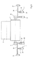
Eine von einer Doppeltragwalzen-Wickelmaschine (Fig. 1) gebildete Wickelvorrichtung weist zwei Tragwalzen 1, 2 auf, von denen mindestens eine angetrieben ist. Die Tragwalzen 1, 2 bilden ein Walzenbett, in dem mehrere nebeneinanderliegende Wickelrollen 3 während des Aufwickelns auf den Tragwalzen 1, 2 aufliegen. Von einer (nicht dargestellten) Längsschneideinrichtung wird eine Materialbahn, insbesondere eine Papier- oder Kartonbahn, vor dem Aufwickeln in mehrere Einzelbahnen geschnitten, die anschließend durch den Spalt zwischen den Tragwalzen 1, 2 oder seitlich um den Mantel einer der beiden Tragwalzen 1, 2 herum in das Walzenbett geführt werden, wo sie auf fluchtend aufgereihte Hülsen 4 aufgewickelt werden.A winding device formed by a double-winder winding machine (Fig. 1) has two
Die Tragwalze 1 ist über ein Lager 5 auf einem Positioniermittel 6 gelagert, das einen Aktor 7, eine Feder 8, einen Dämpfer 9 und eine Messeinrichtung 10 umfasst. Diese erzeugt entsprechend der aktuellen Position der Tragwalze 1 ein Signal, das die Messeinrichtung 10 an den Aktor 7 weitergibt, so dass dieser entsprechend einer Abweichung zwischen einer Ist-Position und einer geforderten Soll-Position der Tragwalze 1 einen Kolben 11 eines hydraulischen oder pneumatischen Zylinders 12 betätigt. Anstelle des Zylinders 12 kann auch ein elektromotorisches Verstellmittel, beispielsweise ein pneumatisch betriebener Balgzylinder oder eine Rollmembran zum Einsatz kommen. Der Kolben 11 drückt seinerseits auf die Feder 8, und diese wirkt auf die Tragwalze 1 ein.The
Wenn diese in Schwingungen geraten sollte, werden die Schwingungen durch den Dämpfer 9 rasch gedämpft. Der Dämpfer 9 ist ein Element zur Dissipation der Schwingungsenergie und umfasst beispielsweise einen mit einem Gas gefüllten Zylinder 13. Das Gas wird durch einen Stempel 14 zusammengedrückt, der mit dem Lager 5 verbunden ist. Wenn infolge der Schwingungen der Tragwalze 1 das Lager 5 diese an den Stempel 14 weitergibt, drückt dieser das Gas zusammen, und ein Teil der Schwingungsenergie wird in Wärme umgewandelt. Es versteht sich, dass die Schwingungsenergie auch auf andere Weise aus dem System abgeleitet werden kann, beispielsweise durch elektrische Wirbelströme. Die Tragwalze 2 ist auf einem Lager 15 gelagert, das wie das Lager 5 der Tragwalze 1 gelagert ist. Vorzugsweise lässt sich die Federsteifigkeit der Feder 8 verändern.If this should get into vibration, the vibrations are damped by the
In einem weiteren Ausführungsbeispiel (Fig. 2) ist an dem Lager 5 der Tragwalze 1 eine Linearführung 16 angeordnet, durch die die Höhenposition und/oder die waagrechte Position des Lagers 5 und damit die Position der Tragwalze 1 in Bezug auf die Tragwalze 2 und in Bezug auf den Wickel 3 eingestellt werden kann. Die Tragwalze 2 ist an einer Schwinge 17 schwenkbar um einen Drehpunkt 18 gelagert, um auch ihre Position bezüglich der Tragwalze 1 und des Wickels 3 verändern zu können.In a further embodiment (FIG. 2), a
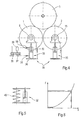
In einem anderen Ausführungsbeispiel (Fig. 3) umfasst der Aktor 7 an beiden Seiten der Welle der Tragwalze 1 als Biegebalken 19, 20 ausgebildete Federn zur elastischen Lagerung der Tragwalze 1, auf die über die Lager 5, 25In another exemplary embodiment (FIG. 3), the
Kolben 21, 22 von Zylindern 23, 24 einwirken. Die Biegebalken 19, 20 drücken ihrerseits gegen die Lager 5, 25 der Tragwalzen 1, 2 und sind in Halterungen 26, 27 befestigt. Die Steifigkeit der Biegebalken 19, 20 lässt sich dadurch verändern, dass die Position der Zylinder 23, 24 in Richtung der Achsen der Biegefedern 19, 20 geändert wird. Beiderseits der Wellenzapfen der Tragwalze 1 ist auch jeweils ein Dämpfer 28, 29 vorgesehen. Mindestens an einer Seite der Tragwalze 1 ist eine Messeinrichtung 30 zur Bestimmung der Position der Tragwalze 1 vorgesehen.
In einem anderen Ausführungsbeispiel (Fig. 4) sind die Tragwalzen 1, 2 auf Positioniermitteln 31 gelagert, die jeweils einen hydraulischen Zylinder 32 bzw. 33 umfassen. Der Zylinder 32 hat eine Ölsäule 34, deren Länge über ein Ventil 35 aus einem Ölvorrat einstellbar ist. Ebenso ist vorzugsweise auch über der Ölsäule 35 in dem Raum des Zylinders 32, in dem sich die Kolbenstange bewegt, ein unter Druck stehender Luftvorrat vorhanden, dessen Druck über ein mit einer Blasenkammer 36 verbundenes Ventil 37 eingestellt wird. Vorzugsweise sind Drosseln 38, 39 vorhanden, über die die Geschwindigkeit, mit der das Öl bzw. die Luft aus dem Innern des Zylinders 32 entweichen können, eingestellt wird.In another embodiment (FIG. 4), the
Der Zylinder 33 ist vorzugsweise genauso aufgebaut, wie am Beispiel des Zylinders 32 dargestellt ist.The
Parallel zu dem Zylinder 32, 33 oder anstelle der Feder 8 (Fig. 1, 2) lässt sich auch eine Feder 40 mit einer nicht-linearen Kennlinie verwenden, um die Lager 5, 15 der Tragwalzen 1, 2 zu lagern.Parallel to the
Im Weg-Kraft-Diagramm (Fig. 6), in dem die Federkraft (F) als Funktion des von der Feder zurückgelegten Weges (s) dargestellt ist, weist die Federkennlinie der Feder 40 mit zunehmendem Weg s eine stärkere Steigung auf; d. h. die Feder 40 hat eine nicht-lineare Federkennlinie und wirkt um so härter, je größer der zurückgelegte Federweg ist.In the path-force diagram (Figure 6), in which the spring force (F) is shown as a function of the distance traveled by the spring (s), the spring characteristic of the
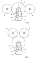
In einem anderen Ausführungsbeispiel ist eine Stützwalzen-Wickelmaschine (Fig. 7) mit einer Stützwalze 41 dargestellt, gegen die zwei Wickelrollen 42, 43 jeweils in Neun-Uhr-Position bzw. in Drei-Uhr-Position abgestützt werden. Die Wickelrollen 42, 43 werden von (hier nicht dargestellten) Tragvorrichtungen getragen und gegen den Mantel der Stützwalze 41 gedrückt. Die Stützwalze 41 ist über ein Lager 44 auf einem Positioniermittel 45 gelagert, das wie das Positioniermittel 6 einen Aktor 46, eine Feder 47, einen Dämpfer 48 und eine Messeinrichtung 49 umfasst.In another embodiment, a back-up roll winding machine (Figure 7) is shown with a back-
Ebenso wie in der anhand von Fig. 1 bis 3 dargestellten Tragwalzen-Wickelmaschine kann in der Stützwalzen-Wickelmaschine eine Stell- oder eine Regeleinrichtung angeordnet sein, um die Position des Positioniermittels 45 entsprechend dem sich während des Aufwickelvorgangs ändernden Gewicht der Wickelrollen 40, 41 anzupassen.As in the carrier roll winding machine illustrated with reference to FIGS. 1 to 3, a setting or control device can be arranged in the backup roll winding machine to adjust the position of the positioning means 45 according to the weight of the winding rolls 40, 41 changing during the winding operation ,
In Fig. 8 ist eine weitere Ausführungsform einer Stützwalzen-Wickelmaschine dargestellt, bei der Wickelrollen 50, 51 gegen eine Stützwalze 52 angestellt sind. Im Übrigen ist ein Positioniermittel vorhanden, das den gleichen Aufbau wie das Positioniermittel 45 gemäß Fig. 7 hat und daher mit denselben Bezugszeichen bezeichnet ist.In Fig. 8, another embodiment of a backup roll winding machine is shown, are employed in the winding
- 11
- Tragwalzeking roll
- 22
- Tragwalzeking roll
- 33
- Wickelrollereel
- 44
- Hülseshell
- 55
- Lagercamp
- 66
- Positioniermittelpositioning
- 77
- Aktoractuator
- 88th
- Federfeather
- 99
- Dämpferdamper
- 1010
- Messeinrichtungmeasuring device
- 1111
- Kolbenpiston
- 1212
- Zylindercylinder
- 1313
- Zylindercylinder
- 1414
- Stempelstamp
- 1515
- Lagercamp
- 1616
- Linearführunglinear guide
- 1717
- Schwingewing
- 1818
- Drehpunktpivot point
- 1919
- Biegebalkenbending beam
- 2020
- Biegebalkenbending beam
- 2121
- Kolbenpiston
- 2222
- Kolbenpiston
- 2323
- Zylindercylinder
- 2424
- Zylindercylinder
- 2525
- Lagercamp
- 2626
- Halterungbracket
- 2727
- Halterungbracket
- 2828
- Dämpferdamper
- 2828
- Dämpferdamper
- 3030
- Messeinrichtungmeasuring device
- 3131
- Positioniermittelpositioning
- 3232
- Zylindercylinder
- 3333
- Zylindercylinder
- 3434
- Ölsäuleoil column
- 3535
- Ölsäuleoil column
- 3636
- Blasenkammerbubble chamber
- 3737
- VentilValve
- 3838
- Drosselthrottle
- 3939
- Drosselthrottle
- 4040
- Federfeather
- 4141
- Stützwalzesupporting roll
- 4242
- Wickelrollereel
- 4343
- Wickelrollereel
- 4444
- Lagercamp
- 4545
- Positioniermittelpositioning
- 4646
- Aktoractuator
- 4747
- Federfeather
- 4848
- Dämpferdamper
- 4949
- Messeinrichtungmeasuring device
- 5050
- Wickelrollereel
- 5151
- Wickelrollereel
- 5252
- Stützwalzesupporting roll
Claims (10)
dadurch gekennzeichnet,
dass das Einfedern der Walze (1, 2; 41; 52) infolge der sich während des Aufwickelns ändernden Masse (mW) der Wickelrolle (3; 42, 43; 50, 51) entsprechend einer vorher festlegten oder durch ein adaptives oder selbstlernendes System anpassbaren Federsteifigkeit (cL) je Walzenseite als Funktion (cL = f(mW)) der Masse (mW) der Wickelrolle (3; 42, 43; 50, 51) erfolgt.Winding machine for winding a material web, in particular a paper or board web, onto at least one winding tube (4) to form a winding reel (3; 42, 43; 50, 51) by means of at least one elastically mounted roller (1, 2; 41; 52), on which the winding roll (3; 42, 43; 50, 51) rests or rests during winding,
characterized,
in that the deflection of the roll (1, 2, 41, 52) as a result of the mass (m W ) of the winding roll (3; 42, 43; 50, 51) changing during the winding process corresponds to a predetermined or an adaptive or self-learning system adjustable spring stiffness (c L ) per roll side as a function (c L = f (m W )) of the mass (m W ) of the winding roll (3; 42, 43; 50, 51) takes place.
dadurch gekennzeichnet,
dass das System (6; 45) einen Aktor (7; 46), eine Feder (8; 40; 47), insbesondere mit einer nicht-linearen Federkennlinie, einen Dämpfer (9; 48) und eine Messeinrichtung (10, 30; 49) umfasst.Winding machine according to claim 1,
characterized,
in that the system (6; 45) has an actuator (7; 46), a spring (8; 40; 47), in particular with a non-linear spring characteristic, a damper (9; 48) and a measuring device (10,30; ).
dadurch gekennzeichnet,
dass die Federsteifigkeit der Feder (8; 40; 47) und/oder die Dämpfung des Dämpfers (9; 48) veränderbar ist.Winding machine according to claim 1 or 2,
characterized,
that the spring stiffness of the spring (8; 40; 47) and / or the damping of the damper (9; 48) is variable.
dadurch gekennzeichnet,
dass der Dämpfer einen Dämpfungszylinder umfasst, der mit einem elektrorheologischen oder einem magnetorheologischen Fluid befüllt ist, dessen Dämpfung durch Änderung eines angelegten elektrischen bzw. magnetischen Feldes veränderbar ist.Winding machine according to claim 3,
characterized,
that the damper comprises a damping cylinder which is filled with an electrorheological or a magnetorheological fluid whose damping is variable by changing an applied electric or magnetic field.
dadurch gekennzeichnet,
dass die Feder als Biegebalken (19, 20) ausgebildet ist.Winding machine according to one of claims 2, 3 or 4,
characterized,
that the spring is designed as a bending beam (19, 20).
dadurch gekennzeichnet,
dass die mindestens eine Walze (1, 2; 41; 52) mit einem Element (16) ausgestattet ist, mit dem die mindestens eine Walze (1, 2; 41; 52) in senkrechter Richtung oder in Richtung zu einer anderen Walze (1, 2; 41; 52) verschiebbar ist.Winding machine according to one of the preceding claims,
characterized,
in that the at least one roller (1, 2; 41; 52) is provided with an element (16) with which the at least one roller (1, 2; 41; 52) moves in a vertical direction or in the direction of another roller (1 , 2, 41, 52) is displaceable.
dadurch gekennzeichnet,
dass die mindestens eine Walze (1, 2) an einer Schwinge (17) befestigt ist, durch die sie in Richtung zu der anderen Walze (1, 2) verschwenkbar ist.Winding machine according to claim 6,
characterized,
in that the at least one roller (1, 2) is fastened to a rocker (17) by means of which it is pivotable in the direction of the other roller (1, 2).
dadurch gekennzeichnet,
dass die Schwinge (17) stufenlos bezüglich ihrer Länge verstellbar ist.Winding machine according to claim 7,
characterized,
that the rocker (17) is infinitely adjustable in length.
dadurch gekennzeichnet,
dass die Dämpfungs-Charakteristik (d) in Abhängigkeit der sich ändernden Feder- oder Lagersteifigkeit (cL) gemäß der Gleichung
kontinuierlich angepasst wird, wobei cW die Walzensteifigkeit, cL die Lagersteifigkeit je Walzenseite und ω die Kreisfrequenz des zu dämpfenden Schwingungsproblems bedeuten.Method for winding a material web, in particular a paper or board web, in a winding machine onto a winding tube to at least one winding roller (3; 42, 43; 50, 51) by means of at least one elastically mounted roller (1, 2; 41; 52), on which the winding roll (3; 42, 43; 50, 51) rests or rests during winding,
characterized,
that the damping characteristic (d) in dependence of the changing spring or bearing stiffness (c L ) according to the equation
cW is the roll stiffness, cL is the bearing stiffness per roll side and ω is the angular frequency of the vibration problem to be damped.
dadurch gekennzeichnet,
dass die Dämpfung (d) auf einen mittleren Wert zwischen der Biegeeigenfrequenz der Walze (1, 2; 41; 52) und der zweithöchsten Kontakteigenfrequenz der Walze (1, 2; 41; 52) zu den Wickelrollen (3; 42, 43; 50, 51) eingestellt wird oder dass die Dämpfung auf die stärkste Schwingung hin optimiert wird.Method according to claim 9,
characterized,
in that the damping (d) is reduced to an intermediate value between the bending natural frequency of the roller (1, 2; 41; 52) and the second highest contact natural frequency of the roller (1, 2; 41; 52) to the winding rollers (3; 42,43; , 51) or that the damping is optimized for the strongest oscillation.
Applications Claiming Priority (1)
| Application Number | Priority Date | Filing Date | Title |
|---|---|---|---|
| DE102006043639A DE102006043639A1 (en) | 2006-09-18 | 2006-09-18 | winder |
Publications (3)
| Publication Number | Publication Date |
|---|---|
| EP1900663A2 true EP1900663A2 (en) | 2008-03-19 |
| EP1900663A3 EP1900663A3 (en) | 2008-12-24 |
| EP1900663B1 EP1900663B1 (en) | 2011-04-20 |
Family
ID=38754762
Family Applications (1)
| Application Number | Title | Priority Date | Filing Date |
|---|---|---|---|
| EP07116417A Not-in-force EP1900663B1 (en) | 2006-09-18 | 2007-09-14 | Method for winding a web material |
Country Status (3)
| Country | Link |
|---|---|
| EP (1) | EP1900663B1 (en) |
| AT (1) | ATE506306T1 (en) |
| DE (2) | DE102006043639A1 (en) |
Cited By (6)
| Publication number | Priority date | Publication date | Assignee | Title |
|---|---|---|---|---|
| EP2135828A3 (en) * | 2008-06-18 | 2010-12-08 | Metso Paper, Inc. | Winding apparatus of fibrous web and method for winding fibrous web |
| EP2341023A3 (en) * | 2009-12-29 | 2012-03-28 | Voith Patent GmbH | Roll winding device and method for winding a sheet of material |
| CN108673952A (en) * | 2018-08-01 | 2018-10-19 | 浙江环龙机器有限公司 | A kind of plug regulating device |
| CN111115327A (en) * | 2019-12-25 | 2020-05-08 | 晋江圣翔机械有限公司 | Discharge control system of a cutting machine |
| CN115893059A (en) * | 2022-11-25 | 2023-04-04 | 齐齐哈尔建华机械有限公司 | A semi-automatic rolling paper tooling for assembling propaganda paper positions for propaganda bombs |
| CN118771040A (en) * | 2024-09-11 | 2024-10-15 | 常州丰兴诚环保科技有限公司 | A thickened prepreg finished product winding device |
Families Citing this family (2)
| Publication number | Priority date | Publication date | Assignee | Title |
|---|---|---|---|---|
| DE102011112032A1 (en) * | 2011-08-31 | 2013-02-28 | Andritz Küsters Gmbh | Process for winding cut fed winding material and double carrier roll |
| CN117864535A (en) * | 2023-03-14 | 2024-04-12 | 马鞍山森奎科技有限公司 | Film shrinking machine for film processing |
Citations (9)
| Publication number | Priority date | Publication date | Assignee | Title |
|---|---|---|---|---|
| DE7121923U (en) | 1971-06-05 | 1972-11-30 | J Voith Gmbh | CARRYING DEVICE FOR ROLLS WINDED FROM TRACKS |
| DE2318351B1 (en) | 1973-04-12 | 1974-07-25 | J.M. Voith Gmbh, 7920 Heidenheim | Carrying device for a winding roll |
| DE7305837U (en) | 1973-02-16 | 1974-10-10 | Voith J Gmbh | CARRYING DEVICE FOR ROLLS WINDED FROM TRACKS |
| EP0792245B1 (en) | 1995-11-01 | 1999-06-09 | Valmet Corporation | Method in winding |
| DE20013319U1 (en) | 2000-08-02 | 2000-09-28 | Voith Sulzer Papiertechnik Patent GmbH, 89522 Heidenheim | Web start fastening |
| EP0829438B1 (en) | 1994-05-26 | 2002-04-03 | Metso Paper, Inc. | Method in winding of a web |
| EP1260470A2 (en) | 2001-05-23 | 2002-11-27 | Voith Paper Jagenberg GmbH | Method and device for active dampening of vibrations in winding machines |
| DE102004062890A1 (en) | 2004-01-06 | 2005-10-13 | Eras Gmbh | Paper web roll has an integral frequency change assembly that changes the winding speed |
| DE102005024266A1 (en) | 2005-05-27 | 2006-11-30 | Voith Patent Gmbh | Reel winding device |
Family Cites Families (1)
| Publication number | Priority date | Publication date | Assignee | Title |
|---|---|---|---|---|
| DE102004000033A1 (en) * | 2004-10-21 | 2006-04-27 | Voith Paper Patent Gmbh | winder |
-
2006
- 2006-09-18 DE DE102006043639A patent/DE102006043639A1/en not_active Withdrawn
-
2007
- 2007-09-14 DE DE502007006980T patent/DE502007006980D1/en active Active
- 2007-09-14 AT AT07116417T patent/ATE506306T1/en active
- 2007-09-14 EP EP07116417A patent/EP1900663B1/en not_active Not-in-force
Patent Citations (9)
| Publication number | Priority date | Publication date | Assignee | Title |
|---|---|---|---|---|
| DE7121923U (en) | 1971-06-05 | 1972-11-30 | J Voith Gmbh | CARRYING DEVICE FOR ROLLS WINDED FROM TRACKS |
| DE7305837U (en) | 1973-02-16 | 1974-10-10 | Voith J Gmbh | CARRYING DEVICE FOR ROLLS WINDED FROM TRACKS |
| DE2318351B1 (en) | 1973-04-12 | 1974-07-25 | J.M. Voith Gmbh, 7920 Heidenheim | Carrying device for a winding roll |
| EP0829438B1 (en) | 1994-05-26 | 2002-04-03 | Metso Paper, Inc. | Method in winding of a web |
| EP0792245B1 (en) | 1995-11-01 | 1999-06-09 | Valmet Corporation | Method in winding |
| DE20013319U1 (en) | 2000-08-02 | 2000-09-28 | Voith Sulzer Papiertechnik Patent GmbH, 89522 Heidenheim | Web start fastening |
| EP1260470A2 (en) | 2001-05-23 | 2002-11-27 | Voith Paper Jagenberg GmbH | Method and device for active dampening of vibrations in winding machines |
| DE102004062890A1 (en) | 2004-01-06 | 2005-10-13 | Eras Gmbh | Paper web roll has an integral frequency change assembly that changes the winding speed |
| DE102005024266A1 (en) | 2005-05-27 | 2006-11-30 | Voith Patent Gmbh | Reel winding device |
Cited By (8)
| Publication number | Priority date | Publication date | Assignee | Title |
|---|---|---|---|---|
| EP2135828A3 (en) * | 2008-06-18 | 2010-12-08 | Metso Paper, Inc. | Winding apparatus of fibrous web and method for winding fibrous web |
| EP2341023A3 (en) * | 2009-12-29 | 2012-03-28 | Voith Patent GmbH | Roll winding device and method for winding a sheet of material |
| CN108673952A (en) * | 2018-08-01 | 2018-10-19 | 浙江环龙机器有限公司 | A kind of plug regulating device |
| CN108673952B (en) * | 2018-08-01 | 2024-02-13 | 山东品圣纸管有限公司 | Mandrel adjusting device |
| CN111115327A (en) * | 2019-12-25 | 2020-05-08 | 晋江圣翔机械有限公司 | Discharge control system of a cutting machine |
| CN111115327B (en) * | 2019-12-25 | 2021-07-27 | 晋江圣翔机械有限公司 | Discharge control system of a cutting machine |
| CN115893059A (en) * | 2022-11-25 | 2023-04-04 | 齐齐哈尔建华机械有限公司 | A semi-automatic rolling paper tooling for assembling propaganda paper positions for propaganda bombs |
| CN118771040A (en) * | 2024-09-11 | 2024-10-15 | 常州丰兴诚环保科技有限公司 | A thickened prepreg finished product winding device |
Also Published As
| Publication number | Publication date |
|---|---|
| DE502007006980D1 (en) | 2011-06-01 |
| DE102006043639A1 (en) | 2008-03-27 |
| EP1900663A3 (en) | 2008-12-24 |
| ATE506306T1 (en) | 2011-05-15 |
| EP1900663B1 (en) | 2011-04-20 |
Similar Documents
| Publication | Publication Date | Title |
|---|---|---|
| EP1900663B1 (en) | Method for winding a web material | |
| EP1260470B1 (en) | Method and device for active dampening of vibrations in winding machines | |
| EP2080722A2 (en) | Roll coiling device and method for coiling a strip of material into a coiled roll of material | |
| DE19629205A1 (en) | Method and device for winding a paper web into a roll with active vibration damping | |
| DE112007000826T5 (en) | Method for damping vibrations in rewinders | |
| EP1739040B1 (en) | Winding machine | |
| EP1650148A2 (en) | Winding machine | |
| DE102005000052A1 (en) | Machine for winding paper or cardboard on to reel has support rollers for reel which are mounted on positioning units which compensate for increasing weight of reel and are fitted with shock absorbers whose damping effect can be adjusted | |
| DE102006043628A1 (en) | King roll winding machine for material web i.e. paper web or cardboard web, has press roller whose pressing force is controlled or regulated over handle corresponding to diameter of winding roller using damping device | |
| EP1900662A2 (en) | Coiling machine | |
| AT506025B1 (en) | METHOD AND DEVICE FOR VIBRATING ROLLING VIBRATIONS | |
| DE7305837U (en) | CARRYING DEVICE FOR ROLLS WINDED FROM TRACKS | |
| EP1683749B1 (en) | Double support roller winding machine | |
| EP2502860B1 (en) | Device for winding a web of material | |
| EP1818296B1 (en) | Roll winding device | |
| DE102009055352A1 (en) | Roll winding device and method for winding a material web | |
| EP1790600B1 (en) | Winder | |
| AT509265B1 (en) | WINDING PART FOR A ROLL CUTTER OF A FIBERWORK AND METHOD FOR MODERNIZING A WRAPPING PART FOR A ROLL CUTTER OF A FIBERWORK | |
| DE102006023831A1 (en) | Roller winding device for use in printing press, has supporting rollers forming winding bed, where winding roller is arranged on bed during winding, and one of rollers has vibration dampers with resonance frequency | |
| DE102008053467A1 (en) | Material roll e.g. paper roll or board roll, rolling method for bearer drum type rewinder device, involves adjusting distance between cylinder system and surface of roll using hydraulic cylinder based on distance measurement | |
| EP2502861B1 (en) | Device and method for winding a sheet of material | |
| DE112011103576B4 (en) | Roller support arrangement of a fiber web machine and partial web winder of a fiber web roll cutting machine | |
| EP1876119B1 (en) | Roll winding device and method for winding a sheet of material | |
| EP1857389A2 (en) | Double bearer drum winder for winding a sheet of material | |
| DE202006004449U1 (en) | Roll winding device for winding-on of material sheet onto winding tube has at least bearing points of one support roller provided with damping units for compensating of bending or torsional oscillations of support roller |
Legal Events
| Date | Code | Title | Description |
|---|---|---|---|
| PUAI | Public reference made under article 153(3) epc to a published international application that has entered the european phase |
Free format text: ORIGINAL CODE: 0009012 |
|
| AK | Designated contracting states |
Kind code of ref document: A2 Designated state(s): AT BE BG CH CY CZ DE DK EE ES FI FR GB GR HU IE IS IT LI LT LU LV MC MT NL PL PT RO SE SI SK TR |
|
| AX | Request for extension of the european patent |
Extension state: AL BA HR MK YU |
|
| PUAL | Search report despatched |
Free format text: ORIGINAL CODE: 0009013 |
|
| AK | Designated contracting states |
Kind code of ref document: A3 Designated state(s): AT BE BG CH CY CZ DE DK EE ES FI FR GB GR HU IE IS IT LI LT LU LV MC MT NL PL PT RO SE SI SK TR |
|
| AX | Request for extension of the european patent |
Extension state: AL BA HR MK RS |
|
| RIC1 | Information provided on ipc code assigned before grant |
Ipc: B65H 18/02 20060101ALI20081118BHEP Ipc: B65H 18/20 20060101AFI20071210BHEP |
|
| 17P | Request for examination filed |
Effective date: 20090624 |
|
| AKX | Designation fees paid |
Designated state(s): AT DE FI IT SE |
|
| 17Q | First examination report despatched |
Effective date: 20091001 |
|
| GRAP | Despatch of communication of intention to grant a patent |
Free format text: ORIGINAL CODE: EPIDOSNIGR1 |
|
| RIC1 | Information provided on ipc code assigned before grant |
Ipc: B65H 18/14 20060101ALI20101011BHEP Ipc: B65H 18/02 20060101AFI20101011BHEP |
|
| RTI1 | Title (correction) |
Free format text: METHOD FOR WINDING A WEB MATERIAL |
|
| GRAS | Grant fee paid |
Free format text: ORIGINAL CODE: EPIDOSNIGR3 |
|
| GRAA | (expected) grant |
Free format text: ORIGINAL CODE: 0009210 |
|
| AK | Designated contracting states |
Kind code of ref document: B1 Designated state(s): AT DE FI IT SE |
|
| REF | Corresponds to: |
Ref document number: 502007006980 Country of ref document: DE Date of ref document: 20110601 Kind code of ref document: P |
|
| REG | Reference to a national code |
Ref country code: DE Ref legal event code: R096 Ref document number: 502007006980 Country of ref document: DE Effective date: 20110601 |
|
| REG | Reference to a national code |
Ref country code: SE Ref legal event code: TRGR |
|
| PGFP | Annual fee paid to national office [announced via postgrant information from national office to epo] |
Ref country code: SE Payment date: 20110923 Year of fee payment: 5 |
|
| PLBE | No opposition filed within time limit |
Free format text: ORIGINAL CODE: 0009261 |
|
| STAA | Information on the status of an ep patent application or granted ep patent |
Free format text: STATUS: NO OPPOSITION FILED WITHIN TIME LIMIT |
|
| 26N | No opposition filed |
Effective date: 20120123 |
|
| REG | Reference to a national code |
Ref country code: DE Ref legal event code: R097 Ref document number: 502007006980 Country of ref document: DE Effective date: 20120123 |
|
| PG25 | Lapsed in a contracting state [announced via postgrant information from national office to epo] |
Ref country code: SE Free format text: LAPSE BECAUSE OF NON-PAYMENT OF DUE FEES Effective date: 20120915 |
|
| REG | Reference to a national code |
Ref country code: SE Ref legal event code: EUG |
|
| PGFP | Annual fee paid to national office [announced via postgrant information from national office to epo] |
Ref country code: AT Payment date: 20130911 Year of fee payment: 7 Ref country code: DE Payment date: 20130919 Year of fee payment: 7 Ref country code: FI Payment date: 20130911 Year of fee payment: 7 |
|
| PGFP | Annual fee paid to national office [announced via postgrant information from national office to epo] |
Ref country code: IT Payment date: 20130930 Year of fee payment: 7 |
|
| REG | Reference to a national code |
Ref country code: DE Ref legal event code: R119 Ref document number: 502007006980 Country of ref document: DE |
|
| PG25 | Lapsed in a contracting state [announced via postgrant information from national office to epo] |
Ref country code: FI Free format text: LAPSE BECAUSE OF NON-PAYMENT OF DUE FEES Effective date: 20140914 |
|
| REG | Reference to a national code |
Ref country code: AT Ref legal event code: MM01 Ref document number: 506306 Country of ref document: AT Kind code of ref document: T Effective date: 20140914 |
|
| REG | Reference to a national code |
Ref country code: DE Ref legal event code: R119 Ref document number: 502007006980 Country of ref document: DE Effective date: 20150401 |
|
| PG25 | Lapsed in a contracting state [announced via postgrant information from national office to epo] |
Ref country code: DE Free format text: LAPSE BECAUSE OF NON-PAYMENT OF DUE FEES Effective date: 20150401 |
|
| PG25 | Lapsed in a contracting state [announced via postgrant information from national office to epo] |
Ref country code: AT Free format text: LAPSE BECAUSE OF NON-PAYMENT OF DUE FEES Effective date: 20140914 Ref country code: IT Free format text: LAPSE BECAUSE OF NON-PAYMENT OF DUE FEES Effective date: 20140914 |