EP1900447A2 - Vorrichtung zum Sortieren von Postsendungen - Google Patents
Vorrichtung zum Sortieren von Postsendungen Download PDFInfo
- Publication number
- EP1900447A2 EP1900447A2 EP07254420A EP07254420A EP1900447A2 EP 1900447 A2 EP1900447 A2 EP 1900447A2 EP 07254420 A EP07254420 A EP 07254420A EP 07254420 A EP07254420 A EP 07254420A EP 1900447 A2 EP1900447 A2 EP 1900447A2
- Authority
- EP
- European Patent Office
- Prior art keywords
- group
- sorting
- arm
- compartments
- sorting compartments
- Prior art date
- Legal status (The legal status is an assumption and is not a legal conclusion. Google has not performed a legal analysis and makes no representation as to the accuracy of the status listed.)
- Withdrawn
Links
- 230000007246 mechanism Effects 0.000 claims abstract description 73
- 238000000034 method Methods 0.000 claims 2
- 238000006243 chemical reaction Methods 0.000 description 8
- 229910000831 Steel Inorganic materials 0.000 description 5
- 239000010959 steel Substances 0.000 description 5
- 239000000463 material Substances 0.000 description 4
- 230000008901 benefit Effects 0.000 description 3
- 230000008859 change Effects 0.000 description 3
- 238000012163 sequencing technique Methods 0.000 description 2
- 239000004743 Polypropylene Substances 0.000 description 1
- 238000001125 extrusion Methods 0.000 description 1
- 239000011159 matrix material Substances 0.000 description 1
- 239000002184 metal Substances 0.000 description 1
- 230000004048 modification Effects 0.000 description 1
- 238000012986 modification Methods 0.000 description 1
- 239000004033 plastic Substances 0.000 description 1
- -1 polypropylene Polymers 0.000 description 1
- 229920001155 polypropylene Polymers 0.000 description 1
- 230000000284 resting effect Effects 0.000 description 1
- 230000001360 synchronised effect Effects 0.000 description 1
- 230000000007 visual effect Effects 0.000 description 1
Images









Classifications
-
- B—PERFORMING OPERATIONS; TRANSPORTING
- B07—SEPARATING SOLIDS FROM SOLIDS; SORTING
- B07C—POSTAL SORTING; SORTING INDIVIDUAL ARTICLES, OR BULK MATERIAL FIT TO BE SORTED PIECE-MEAL, e.g. BY PICKING
- B07C7/00—Sorting by hand only e.g. of mail
- B07C7/02—Compartmented furniture, e.g. pigeon-holes
Definitions
- the present invention relates to apparatus for sorting postal items.
- the present invention relates to apparatus for sorting postal items that includes a translation mechanism for translating between a first and second configuration.
- the postal items are sorted in a general manner. That is, the postal items are separated according to a specific mail route that a postal worker, such as a postal delivery person, is designated to carry out.
- the postal items may be generally sorted to specific regions or suburbs of a town or city.
- the postal items are sorted into sequence.
- the sequence is arranged so that the postal delivery person is able to sequentially deliver the postal items to specific addresses or delivery points in order so that delivery of the postal items on the postal route is as time and energy efficient as possible.
- the present invention aims to overcome, or at least alleviate, some or all of the afore-mentioned problems.
- the present invention provides apparatus for sorting postal items, the apparatus comprising at least two groups of sorting compartments and a translation mechanism, wherein a first and second group of sorting compartments move relative to each other and translate, using the translation mechanism, between a first and second working configuration.
- the below described postal sorting apparatus is designed to sort postal products, documents and parcels for delivery to the intended destination.
- the apparatus contains two types of sorting apparatus in a single unit.
- the sorting apparatus contains a unit for general sorting and a unit for sequence sorting. When the general sorting unit is not required, the unit is stored in a position away from the sequencing unit and does not obstruct in any way access to the sequencing unit or the areas under the work surface where the operator may sit.
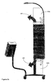
- Figure 1 shows a general arrangement of a postal sorting apparatus according to this first embodiment of the present invention.
- a steel RHS (rectangular hollow section) frame 101 is provided that is used to support different elements of the sorting apparatus. Attached to the frame 101 are legs 103 with lockable caster wheels 105 attached thereto.
- the frame is made from steel in this embodiment. However, it will be understood that the frame could be made from any other suitable material.
- the sorting apparatus includes two groups of sorting compartments providing two separate sorting areas for sorting postal items either into a specific sequence or for more general sorting.
- the sorting compartments are provided as a matrix of steel compartments.
- the compartments may be made from any other suitable material.
- plastic sorting trays are inserted into the compartments to allow an operator to sort the postal items.
- the sorting trays are made from polypropylene in this embodiment. However, it will be understood that any other suitable material may be used as an alternative.
- a group of sequence sorting compartments 107 are provided. Also provided are a group of general sorting compartments (109a, 109b). The group of general sorting compartments is split into two separate groups, a first upper group 109a of general sorting compartments and a second lower group 109b of general sorting compartments.
- the upper group 109a is arranged to be located above the group of sequence sorting compartments 107 while the lower group 109b is arranged to be located below the group of sequence sorting compartments 107. This enables an operator to carry out sequence sorting of the postal items utilising the sequence sorting compartments.
- the upper and lower groups of general sorting compartments (109a, 109b) are arranged to be located in front of the group of sequence sorting compartments 107, as will be explained below, in order to enable the operator to carry out general sorting of the postal items.
- a lighting mechanism 111 Attached to the upper portion of the frame 101 is a lighting mechanism 111. This provides additional light for the operator to work in, should they need it.
- a work surface 113 is provided immediately below the group of sequence sorting compartments 107.
- the work surface is arranged to slide out from the frame 101 to provide a surface for an operator to sort postal items on.
- the surface is generally used when the operator is carrying out sequential sorting of the postal items.
- the work surface 113 can be retracted by sliding it back underneath the group of sequence sorting compartments 107.
- a box holder 115 is provided to hold containers with postal items for general sorting.
- the box holder 115 is located on a box holder frame 117, which forms part of the main frame 101.
- the box holder is used for postal items yet to be sorted in the general sorting compartments.
- the general sorting is completed for the delivery office or when a general sorting compartment is full, the postal items will be cleared down and the postal delivery people will collect all the postal items for a particular delivery route from each general sorting apparatus throughout the delivery office and combine them together.
- the sorting apparatus arrangement described above provides a work space 119 around the sorting compartments for the operator to work in.
- linear actuators 121 Located within each side of the frame are linear actuators 121 that are arranged to provide a lifting mechanism to the frame 101 upon the depression of a switch, as will be explained in more detail below.
- the linear actuators 121 include gas struts for controlling the height adjustment operation.
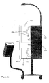
- Figures 2A to 2H show details of how to make a change from a first working configuration to a second working configuration, and back again. That is, the apparatus is changed from a sequence sorting configuration to a general sorting configuration, and back again.
- Figure 2A shows the sorting apparatus in a first working configuration. This first configuration is used for the sequential sorting of postal items.
- the first step is for the operator to push the work surface 113 underneath the group of sequence sorting compartments 107, as indicated by the arrow 201.
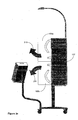
- FIG 2B the apparatus is shown in an initial position just prior to when the operator starts to move the groups of general sorting compartments (109a, 109b).
- the operator moves the groups of general sorting compartments by either pulling the lower group of general sorting compartments 109b upwards towards the upper group of general sorting compartments in the direction of the arrow 205, or by pulling the upper group of general sorting compartments 109a down towards the lower group of general sorting compartments in the direction as shown by the arrow 207.
- Only one group (upper or lower) of general sorting compartments (109a, 109b) is required to be moved by the operator due to the translation mechanism, which will be explained in more detail below.
- the apparatus is shown as the operator continues to move either the upper or lower group of general sorting compartments in the direction of the respective arrows 205 or 207.
- Figure 2D shows the apparatus arranged in the second working configuration. That is, the second working configuration enables the operator to sort postal items in a general manner using the general sorting compartments.
- Arm mechanisms 203 are shown that form part of the translation mechanism, as will be explained in more detail below.
- the upper and lower groups of general sorting compartments (109a, 109b) are positioned in front of the group of sequence sorting compartments 107 to at least partially obscure the sequence sorting compartments.
- the work surface 113 is pulled out from underneath the group of sequence sorting compartments 107 in the direction of the arrow 209. The work surface 113 provides support to the group of general sorting compartments.
- Figure 2E shows the steps required for reconfiguring the sorting apparatus from the second working configuration back into the first working configuration.
- the operator first needs to push the work surface 113 underneath the group of sequence sorting compartments 107.
- the operator can then move either the upper or lower group of general sorting compartments (109a, 109b) towards himself as shown by arrows 211 or 213. Only one group of general sorting compartments is required to be moved by the operator as will be explained in more detail below.
- Figure 2F shows the upper and lower group of general sorting compartments (109a, 109b) moving upwards and downwards respectively.
- Figure 2G shows the upper and lower group of general sorting compartments (109a, 109b) in position above and below the sequence sorting compartments.
- Figure 2H shows the sorting apparatus back in the first working configuration with the work surface 113 pulled out in the direction of the arrow 215.
- Figure 3 shows a switch arrangement for use in this embodiment.
- an electrical switch 303 for operation of the light 111.
- Located directly above the light switch 303 is a label 305 identifying the switch as the light switch.
- the label 305 is positioned on the front edge of the work surface such that the operator can locate the light switch with ease.
- Two further switches (307a, 307b) are provided on the underside of the work surface towards the left hand edge of the work surface. These are used to reset the height position of the sorting frame 101 to a height stored in memory.
- the two switches are connected to a control mechanism that can monitor the height of the frame by measuring a distance on the linear actuators 121.
- the linear actuators are controlled by a drive mechanism to change the height of the frame according to the memorised value.
- a further switch 309 is arranged to provide a manual control of the height of the frame 101.
- the switch 309 has two height adjustment operations, up and down.
- a label 311 is provided on the front edge of the work surface above the switches to provide the operator with an indication of where the switches are and what purpose they serve.
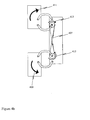
- Figure 4A shows a translation mechanism according to this embodiment of the present invention.
- the translation mechanism provides a means to easily translate the group of general sorting compartments from one position to a second position.
- the translation mechanism includes an arm mechanism 401.
- a further arm mechanism is provided on the opposite side of the apparatus and consists of a similar arrangement described below but in a mirrored format.
- the arm mechanism 401 includes first, second, third and fourth arcuate arms (403 a, b, c, d).
- the first, second, third and fourth arms are attached at one end to the frame 101 by a bearing arrangement that includes a pin and bush.
- the first and second arms (403a, b) are connected at one end to the upper group of general sorting compartments, and the third and fourth arms (403c, d) are connected at one end to the lower group of general sorting components.
- the connection is made using a bearing arrangement, such as a pin and bush.
- the mirror image of this configuration is provided on the opposite side of the upper and lower groups of general sorting components.
- the arm mechanism 401 also includes first and second rotational devices (405a, b), such as pulleys.
- the pulleys are attached to the frame at the same point as the second and third arms.
- the pulleys are also attached to the second and third arms such that when the pulleys rotate, the second and third arms pivot at the point of attachment.
- a linkage device 407 such as a cable, is provided.
- the cable is attached between the pulleys such that when a first pulley is caused to rotate, the cable causes the second pulley to rotate in the opposite direction.
- the cable is crossed over between the first and second pulley. This causes opposing movement of the upper and lower groups of general sorting compartments.
- One group of general sorting compartments is counterbalanced by the other group, thus providing a mechanism that enables the operator to easily move the groups of general sorting compartments (109a, 109b).
- Figure 4B shows the arm mechanism in operation.
- the first and second pulleys (413, 415) are shown to be moving, in a rotating manner, in opposite directions. This causes the upper and lower groups of general sorting compartments to move in the direction of the arrows (409, 411) away from each other. It will therefore be understood that moving one of the upper and lower groups of general sorting compartments in the opposite direction will cause the upper and lower groups of general sorting compartments to move towards each other.
- Figure 4C shows the sorting apparatus in the first working configuration.
- the pulleys (413, 415) and cable 407 are no longer moving and the upper group 109a and lower group 109b of general sorting compartments are arranged above and below the group of sequence sorting compartments respectively.
- Figure 5 shows the work surface 113 in more detail.
- the work surface includes a raised edge 501 that enables an operator to sort through postal items while reducing the chance of postal items falling off the work surface. Further, the work surface includes a rounded edge to stop the operator from injuring themselves.
- FIG 6A shows a sorting tray in a first configuration according to this embodiment.
- a sorting tray 601 is shown when inserted inside one of the compartments forming the group of sequence sorting compartments.
- the sorting tray 601 is removable from the compartment.
- a number of vertical dividers 603 are provided for sequence sorting postal items. The vertical dividers are placed into vertically arranged slots 605.
- Figure 6B shows an arrangement of sorting trays within a group of sequence sorting compartments. Again the sorting trays can be removed from the compartments.
- a sorting tray 607 is provided with horizontal dividers 609 located on extrusions 611 within the sorting tray 607.
- the amount of postal items a delivery point would receive determines whether vertical or horizontal dividers are used in the sorting trays for sequential sorting. Some commercial customers who receive large volumes of mail and those that receive a large number of magazines or A4 size type material, for example, would have horizontal dividers whereas for most residential delivery points vertical dividers will suffice.
- Figure 7 shows a sorting tray with a moveable display device.
- the figure shows two sorting trays (701 a, b) removed from the sorting compartments.
- the first sorting tray includes a display device 703a that is located at a front lower edge of the sorting tray 701 a.
- the display device 703a is positioned such that it is parallel to the back wall of the sorting tray.
- the display device 703b is positioned such that it is at a 45 degree angle to the back wall of the sorting tray 701 b.
- the display device includes a display surface 705 for attaching any suitable display thereto.
- a slot 707 is provided on a side portion of the sorting tray to accommodate a locating portion 709 extending from the display device.
- the locating portion 709 locates in the slot 707 and provides the display device with limited movement through a predetermined angle. This mechanism enables an operator to adjust the display on the sorting trays depending on the configuration of the sorting apparatus so that the operator can easily see
- Figure 8 shows a further sorting apparatus arrangement according to a second embodiment.
- the second embodiment includes all the features of the above described first embodiment.
- a computing device 801 is provided with a suitable interface input device, such as a keyboard or touch screen display.
- the computing device also includes a visual display 803.
- the computing device 801 is connected to a database 805.
- the computer is connected to the database via a local area network (LAN).
- LAN local area network
- the computer may be connected to the database using any suitable means, whether the database is on site with the sorting apparatus or situated at a different location.
- the database maybe located at a central headquarters and access to it may be via an Internet connection or wide area network (WAN).
- WAN wide area network
- the sorting apparatus also includes linear actuators 807 as shown in the first embodiment.
- An operator using the sorting apparatus logs into the computer using a unique user identification, and optionally a password.
- Postal sorting information associated with the operator is retrieved from the database 805 and transferred to the computer 801. The information is then displayed on the display 803.
- the information may include the sorting areas that the operator is responsible for. Further, the information may provide details of any redirections, mailstops or other postal related information associated with the operator's sorting actions. In this manner, the operator has an easily readable display providing relevant information about their sort task.
- the computing device 801 is connected to the linear actuators via any suitable output interface.
- a record of the desired height of the sorting apparatus frame is provided, and a value, such as a voltage, is output to the linear actuator in order to move the frame of the sorting apparatus to the desired height associated with the operator.
- the height information may be recorded when the operator first logs in to the computer system.
- the height is first manually adjusted by using the height adjustment mechanism discussed above in the first embodiment. Once the desired height is reached, the user activates an option using the computer to store the desired height.
- a reading that corresponds with the current position of the linear actuators is obtained and stored in the computing device 801. Any suitable electric or electronic device can be used in tandem with the linear actuators to read, monitor and control the height position of the apparatus.
- Figure 9 shows a further sorting apparatus arrangement according to a third embodiment.
- the third embodiment includes all the features of the above described first embodiment.
- a computing device 901 is provided with a suitable interface input device, such as a keyboard or touch screen display.
- Each sorting compartment 905 includes a display 903 that is connected to the computer 901.
- a unique identification, and optionally a password information associated with the sequential sorting of the mail items associated with that operator is displayed on the display 903 that is located on the individual sorting compartments 903.
- any operator can use any sorting apparatus, and the apparatus can be automatically arranged to show information pertaining to the postal sequences that that particular operator is to sort.
- Figure 10A shows a further sorting apparatus arrangement according to a fourth embodiment.
- the group of sequence sorting compartments 1001 is the same as in the above described first embodiment.
- the group of general sorting compartments 1003 is not split into two separate groups as in the first embodiment but instead consists of only one group.
- the group of general sorting compartments is located above the group of sequence sorting compartments, so that the operator can access the sequence sorting compartments to sort the postal items into a postal run sequence.
- the group of general sorting compartments may be located below the group of sequence sorting compartments.
- the group of general sorting compartments When an operator wishes to carry out general sorting of postal items, the group of general sorting compartments is moved from the first working configuration to a second working configuration, where the group of general sorting compartments 1003 are located in front of the group of sequence sorting compartments 1001.
- an arm mechanism arrangement 1101 forming part of the translation mechanism is used that enables the group of general sorting compartments to be translated from the first working configuration to the second working configuration.
- Two arcuate arms are provided on each side of the group of general sorting compartments.
- No counterbalance is provided in this embodiment.
- the group of general sorting compartments may be counterbalanced by attaching a suitable weight at the appropriate point.
- the group of general sorting compartments 1003 comes to a stop on top of the group of sequence sorting compartments to form the first working configuration, and comes to a stop adjacent the group of sequence sorting compartments to form the second working configuration as shown in figure 11B .
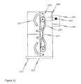
- Figure 12 shows a drive mechanism used in sorting apparatus according to a further embodiment of the invention.
- This drive mechanism is an extra feature that can be included in the translation mechanism as described above in the relevant previous embodiments.
- a motor 1201 that includes a drive mechanism 1203 which has a drive belt 1205 connected thereto.
- the drive belt 1205 connects to an upper pulley 1207, which is a similar pulley to that described above in the first embodiment.
- a power supply 1209 is provided that operates the motor 1201 upon pressing a bi-directional switch 1211 that is located on the underside of the work surface 1213. The switch causes the drive mechanism of the motor to rotate in one of two directions depending on the direction the switch is operated.
- the drive mechanism 1203 rotates, which causes the drive belt 1205 to move.
- the movement of the drive belt 1205 causes the upper pulley 1207 to rotate.
- the rotating pulley 1207 is interconnected with the arm 1215, thus causing the arm to move the upper group of general sorting compartments.
- the upper pulley is linked via a linkage device 1217 to the lower pulley.
- the linkage device 1217 is a cable.
- the cable 1217 is arranged to cause the lower pulley to rotate in an opposite direction to the upper pulley and so move the lower group of general sorting compartments as described above in the first embodiment.
- the motor may be used to move the group of general sorting compartments automatically by operating the switch to drive the motor the desired way, rather than manually.
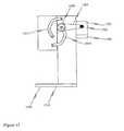
- Figure 13 shows an alternative drive mechanism for use in a sorting apparatus where there is only a single group of general sorting compartments, i.e. the general sorting compartments are not separated into two different groups above and below the sequence sorting compartments.
- the group of general sorting compartments is positioned towards the top of the sorting frame.
- the group may be positioned elsewhere on the sorting frame.
- a motor 1301 is provided with a drive mechanism 1303.
- a drive belt 1305 is connected around the drive mechanism 1303 and the pulley 1307 in a similar way to that described above.
- a power supply 1309 provides power to the motor 1301 via a switch 1311 located on the underside of the work surface 1313. Operating the switch causes the motor to rotate thus driving the drive mechanism.
- the drive mechanism moves the drive belt, which causes the pulley to rotate. As the pulley rotates the arm 1315 moves and causes the group of general sorting compartments to move in the desired direction.
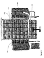
- Figure 14 shows a further alternative wherein additional side compartments are provided to give an increased sequence sorting area.
- a similar arrangement to that described in the first embodiment is used.
- a group of sequence sorting compartments 1401 are provided, with a group of general sorting compartments 1403 split and located above and below the sequence sorting compartments.
- a work surface 1405 is also provided.
- additional side sorting compartments 1407 are provided.
- the additional side sorting compartments 1407 are pivotally attached to the frame of the sorting apparatus such that they can be moved to a desired position suitable for the operator. Alternatively, the additional side sorting compartments may be fixed in position
- the additional side compartments arranged in side cabinets are an extension of the sequence sorting compartments to accommodate the number of delivery points required on a delivery run or route.
- Figure 15A shows a group of sequence sorting compartments 1501, and an upper and lower group of general sorting compartments (1503, 1505) arranged in a working configuration for sorting postal items in a general manner.
- Two rotational devices (1507a, b) are provided, which in this embodiment are an upper and lower pulley. Connected between the upper and lower pulley is a linkage device 1509, which in this embodiment is a cable. The linkage device is connected between the pulleys and arranged such that the pulleys are caused to rotate in opposite directions.
- Two arms are provided, an upper arm 1511 a and a lower arm 1511 b.
- the arms are formed from straight pieces of steel.
- One end of the upper arm is pivotally connected to the frame of the sorting apparatus, and the upper pulley is connected to this end of the upper arm such that the arm and pulley move together.
- a first idler unit 1513a that is arranged such that it is free to rotate.
- a second idler unit 1513b At the other end of the upper arm 1511 a, which is pivotally connected to the upper group of general sorting compartments, is located a second idler unit 1513b, which is also free to rotate.
- An upper toothed belt 1515a is connected between the first and second idler units.
- One end of the lower arm is pivotally connected to the frame of the sorting apparatus, and the lower pulley is connected to this end of the lower arm such that the arm and pulley move together.
- a third idler unit 1513c that is arranged such that it is free to rotate.
- a fourth idler unit 1513d At the other end of the lower arm 1511 a, which is pivotally connected to the lower group of general sorting compartments, is located a fourth idler unit 1513d, which is also free to rotate.
- a lower toothed belt 1515b is connected between the third and fourth idler units.
- Figure 15B shows the position of the upper and lower groups of general sorting compartments when in mid movement from the general sorting working configuration to a sequence sorting working configuration.
- Figure 15C shows the sorting apparatus resting in the sequence sorting working configuration.
- motor mechanisms as described herein may be used as an alternative drive mechanism for the arrangement shown in Figures 15a-c .
- FIG 16 shows a further embodiment of the invention.
- the sorting apparatus 1601 includes a group of sequence sorting compartments 1603 and upper and lower general sorting compartments (1605A, 1605B).
- first, second, third and fourth arcuate arms (1607A, B, C and D) are provided, and are attached in a similar manner to the general sorting compartments as described above in relation to Figure 12 .
- Upper and lower rotational devices (1609A, 1609B), such as pulleys, and a linkage device 1611, such as a cable, are also attached in a similar manner as described above in relation to Figure 12 .
- a shaft mounted geared electric motor 1613 is connected to a lower torque shaft 1615A via the pulley 1609B.
- An upper torque shaft 1615B is connected between the lower arcuate arms of the upper general sorting compartments.
- the work surface of the frame is not shown in the figure for clarity reasons, however it will be understood that it will operate in a similar manner to that described in previous embodiments.
- a corresponding translation mechanism 1617 is provided on the left hand side of the apparatus, which includes four arcuate arms, two rotational devices and a linkage deice to provide support for that side of the general sorting compartments as they move.
- the motor 1613 is controlled by a handheld electronic control module and can be driven in two directions to move the general sorting compartments.
- the control module includes a magnetic backing so that it can be easily stored by attaching it to the metal frame of the apparatus.
- the motor When the motor is operated by the user, the motor directly drives the lower torque shaft either in a clockwise or anti clockwise direction. This causes the lower general sorting compartments to be translated from one sorting configuration to another sorting configuration, as described above. Further, the motor also drives the lower rotational device 1609B, which in turn drives the linkage device 1611, which then drives the upper rotational device 1609A.
- the upper rotational device 1609A rotates, the second arcuate arm 1607B is caused to move at the pivot point where it is attached to the rotational device 1609A. This movement causes the upper general sorting compartments 1605A to move in an opposite direction to the lower general sorting compartments 1605B.
- the upper torque shaft 1615B connected between the two lower arcuate arms attached to the general sorting compartments minimises any twist stress that would otherwise be caused without the torque shafts.
- the embodiment described with reference to figure 16 may be adapted such that the linkage devices are not required.
- separate motors may be used to control the movement of the upper and lower general sorting compartments.
- the separate motors may be controlled via a logic control system that ensures that the upper and lower general sorting compartments are synchronised to move together and in opposite directions to sufficiently counter balance the apparatus.
- the work surface could be adapted such that it automatically retracts before the general sorting compartments are moved.
- the arms are attached at one end to the frame of the apparatus, they may also be pivotally attached to the steel compartment used for sequential sorting the postal items.
- One advantage of an embodiment of the present invention is that groups of sorting compartments are able to be moved from a first configuration to a second configuration in order to optimize the arrangement of sorting compartments. This enables the operator to minimise the amount of height adjustment required when using the sorting apparatus.
- embodiments of the present invention are particularly space efficient by providing a mechanism to move a particular group of sorting compartments when not in use to an area around the apparatus that would otherwise be unused space.
- the ability to move the groups of sorting compartments enables the apparatus to be compacted, therefore saving the use of valuable space in a sorting environment.
- a further advantage provided by embodiments of the present invention is that the sorting module configuration is easily changeable from one working configuration to a second working configuration.
- the working configurations are provided such that an operative is able to work from the same work space.
Landscapes
- Sorting Of Articles (AREA)
Applications Claiming Priority (1)
| Application Number | Priority Date | Filing Date | Title |
|---|---|---|---|
| NZ55368507 | 2007-03-07 |
Publications (2)
| Publication Number | Publication Date |
|---|---|
| EP1900447A2 true EP1900447A2 (de) | 2008-03-19 |
| EP1900447A3 EP1900447A3 (de) | 2008-05-28 |
Family
ID=38931255
Family Applications (1)
| Application Number | Title | Priority Date | Filing Date |
|---|---|---|---|
| EP07254420A Withdrawn EP1900447A3 (de) | 2007-03-07 | 2007-11-09 | Vorrichtung zum Sortieren von Postsendungen |
Country Status (1)
| Country | Link |
|---|---|
| EP (1) | EP1900447A3 (de) |
Cited By (2)
| Publication number | Priority date | Publication date | Assignee | Title |
|---|---|---|---|---|
| RU2504442C1 (ru) * | 2010-03-18 | 2014-01-20 | Солистик | Способ сортировки почтовых отправлений при помощи челночных лотков с переменной емкостью загрузки |
| CN109821779A (zh) * | 2019-01-23 | 2019-05-31 | 嘉兴职业技术学院 | 用于跨境电商的物流分拣系统 |
Citations (1)
| Publication number | Priority date | Publication date | Assignee | Title |
|---|---|---|---|---|
| WO2001060532A1 (en) | 2000-02-16 | 2001-08-23 | Post Danmark | A sorting rack |
Family Cites Families (1)
| Publication number | Priority date | Publication date | Assignee | Title |
|---|---|---|---|---|
| DE478758C (de) * | 1929-07-03 | Otto Gergacsevics | Sortieranlage fuer Postzwecke, insbesondere fuer Briefe u. dgl. |
-
2007
- 2007-11-09 EP EP07254420A patent/EP1900447A3/de not_active Withdrawn
Patent Citations (1)
| Publication number | Priority date | Publication date | Assignee | Title |
|---|---|---|---|---|
| WO2001060532A1 (en) | 2000-02-16 | 2001-08-23 | Post Danmark | A sorting rack |
Cited By (3)
| Publication number | Priority date | Publication date | Assignee | Title |
|---|---|---|---|---|
| RU2504442C1 (ru) * | 2010-03-18 | 2014-01-20 | Солистик | Способ сортировки почтовых отправлений при помощи челночных лотков с переменной емкостью загрузки |
| CN109821779A (zh) * | 2019-01-23 | 2019-05-31 | 嘉兴职业技术学院 | 用于跨境电商的物流分拣系统 |
| CN109821779B (zh) * | 2019-01-23 | 2021-02-02 | 嘉兴职业技术学院 | 用于跨境电商的物流分拣系统 |
Also Published As
| Publication number | Publication date |
|---|---|
| EP1900447A3 (de) | 2008-05-28 |
Similar Documents
| Publication | Publication Date | Title |
|---|---|---|
| US8392019B2 (en) | Modular vending with centralized robotic gantry | |
| US6216890B1 (en) | Display for flat object like floor tile and ceiling tile | |
| US10722032B2 (en) | Chair assemblies, modular components for use within chair assemblies, and parts for use within the modular components | |
| US8620472B2 (en) | Dispensing mechanism for centralized robotic gantry | |
| US20090014461A1 (en) | Pharmaceutical Product Cassette, Pharmaceutical Product Dispensing Apparatus And Pharmaceutical Product Dispensing System | |
| CN204561335U (zh) | 一种自动存取文件的办公桌 | |
| US9643782B1 (en) | Automatic storage and retrieval system with planar motion mechanism | |
| JP2020028919A (ja) | 曲げ加工プレス | |
| US5590794A (en) | Sorting module installation | |
| CN1359507A (zh) | 前部透明的售货机 | |
| CN101395072B (zh) | 自动分配和弹出按纵向平行排行贮存的物件的模块式装置 | |
| JP3285273B2 (ja) | 自動販売機 | |
| CN107973044B (zh) | 一种文件自动整理装置 | |
| NZ553685A (en) | Apparatus for sorting postal items | |
| EP1519163A3 (de) | Faltbare Waagschale für eine Postwaage | |
| CN109472926A (zh) | 一种物品自动售卖系统 | |
| CN219928632U (zh) | 一种便于分类识别的仓储货架 | |
| WO2006096353A2 (en) | Art sheets storage , display and retrieval systems | |
| EP0881609B1 (de) | Ausgabeautomat für Büchlein oder Broschüren | |
| JP2007007099A (ja) | 薬品類カセット及び払出装置ならびに払出システム | |
| CN210407622U (zh) | 课桌 | |
| JP2010120764A (ja) | 物品仕分システム又は物品ピッキングシステム用の誤作業防止装置 | |
| CN119706153A (zh) | 智能存储配送设备、系统及配送方法 | |
| CN221383071U (zh) | 一种展示平台 | |
| CN222690182U (zh) | 一种具有调节功能的立式排队叫号机 |
Legal Events
| Date | Code | Title | Description |
|---|---|---|---|
| PUAI | Public reference made under article 153(3) epc to a published international application that has entered the european phase |
Free format text: ORIGINAL CODE: 0009012 |
|
| 17P | Request for examination filed |
Effective date: 20071126 |
|
| AK | Designated contracting states |
Kind code of ref document: A2 Designated state(s): AT BE BG CH CY CZ DE DK EE ES FI FR GB GR HU IE IS IT LI LT LU LV MC MT NL PL PT RO SE SI SK TR |
|
| AX | Request for extension of the european patent |
Extension state: AL BA HR MK YU |
|
| PUAL | Search report despatched |
Free format text: ORIGINAL CODE: 0009013 |
|
| AK | Designated contracting states |
Kind code of ref document: A3 Designated state(s): AT BE BG CH CY CZ DE DK EE ES FI FR GB GR HU IE IS IT LI LT LU LV MC MT NL PL PT RO SE SI SK TR |
|
| AX | Request for extension of the european patent |
Extension state: AL BA HR MK RS |
|
| STAA | Information on the status of an ep patent application or granted ep patent |
Free format text: STATUS: THE APPLICATION HAS BEEN WITHDRAWN |
|
| 17Q | First examination report despatched |
Effective date: 20080602 |
|
| 18W | Application withdrawn |
Effective date: 20080605 |
|
| EL | Fr: translation of claims filed |