EP1900442A1 - Device and method for coating base material - Google Patents
Device and method for coating base material Download PDFInfo
- Publication number
- EP1900442A1 EP1900442A1 EP05758332A EP05758332A EP1900442A1 EP 1900442 A1 EP1900442 A1 EP 1900442A1 EP 05758332 A EP05758332 A EP 05758332A EP 05758332 A EP05758332 A EP 05758332A EP 1900442 A1 EP1900442 A1 EP 1900442A1
- Authority
- EP
- European Patent Office
- Prior art keywords
- slurry
- channels
- substrate
- air
- flow
- Prior art date
- Legal status (The legal status is an assumption and is not a legal conclusion. Google has not performed a legal analysis and makes no representation as to the accuracy of the status listed.)
- Granted
Links
Images


Classifications
-
- B—PERFORMING OPERATIONS; TRANSPORTING
- B01—PHYSICAL OR CHEMICAL PROCESSES OR APPARATUS IN GENERAL
- B01J—CHEMICAL OR PHYSICAL PROCESSES, e.g. CATALYSIS OR COLLOID CHEMISTRY; THEIR RELEVANT APPARATUS
- B01J37/00—Processes, in general, for preparing catalysts; Processes, in general, for activation of catalysts
- B01J37/02—Impregnation, coating or precipitation
- B01J37/0215—Coating
-
- B—PERFORMING OPERATIONS; TRANSPORTING
- B01—PHYSICAL OR CHEMICAL PROCESSES OR APPARATUS IN GENERAL
- B01J—CHEMICAL OR PHYSICAL PROCESSES, e.g. CATALYSIS OR COLLOID CHEMISTRY; THEIR RELEVANT APPARATUS
- B01J35/00—Catalysts, in general, characterised by their form or physical properties
- B01J35/50—Catalysts, in general, characterised by their form or physical properties characterised by their shape or configuration
- B01J35/56—Foraminous structures having flow-through passages or channels, e.g. grids or three-dimensional [3D] monoliths
-
- B—PERFORMING OPERATIONS; TRANSPORTING
- B05—SPRAYING OR ATOMISING IN GENERAL; APPLYING FLUENT MATERIALS TO SURFACES, IN GENERAL
- B05D—PROCESSES FOR APPLYING FLUENT MATERIALS TO SURFACES, IN GENERAL
- B05D1/00—Processes for applying liquids or other fluent materials
- B05D1/002—Processes for applying liquids or other fluent materials the substrate being rotated
-
- B—PERFORMING OPERATIONS; TRANSPORTING
- B05—SPRAYING OR ATOMISING IN GENERAL; APPLYING FLUENT MATERIALS TO SURFACES, IN GENERAL
- B05D—PROCESSES FOR APPLYING FLUENT MATERIALS TO SURFACES, IN GENERAL
- B05D2254/00—Tubes
- B05D2254/04—Applying the material on the interior of the tube
-
- B—PERFORMING OPERATIONS; TRANSPORTING
- B05—SPRAYING OR ATOMISING IN GENERAL; APPLYING FLUENT MATERIALS TO SURFACES, IN GENERAL
- B05D—PROCESSES FOR APPLYING FLUENT MATERIALS TO SURFACES, IN GENERAL
- B05D3/00—Pretreatment of surfaces to which liquids or other fluent materials are to be applied; After-treatment of applied coatings, e.g. intermediate treating of an applied coating preparatory to subsequent applications of liquids or other fluent materials
- B05D3/04—Pretreatment of surfaces to which liquids or other fluent materials are to be applied; After-treatment of applied coatings, e.g. intermediate treating of an applied coating preparatory to subsequent applications of liquids or other fluent materials by exposure to gases
-
- B—PERFORMING OPERATIONS; TRANSPORTING
- B05—SPRAYING OR ATOMISING IN GENERAL; APPLYING FLUENT MATERIALS TO SURFACES, IN GENERAL
- B05D—PROCESSES FOR APPLYING FLUENT MATERIALS TO SURFACES, IN GENERAL
- B05D3/00—Pretreatment of surfaces to which liquids or other fluent materials are to be applied; After-treatment of applied coatings, e.g. intermediate treating of an applied coating preparatory to subsequent applications of liquids or other fluent materials
- B05D3/04—Pretreatment of surfaces to which liquids or other fluent materials are to be applied; After-treatment of applied coatings, e.g. intermediate treating of an applied coating preparatory to subsequent applications of liquids or other fluent materials by exposure to gases
- B05D3/0406—Pretreatment of surfaces to which liquids or other fluent materials are to be applied; After-treatment of applied coatings, e.g. intermediate treating of an applied coating preparatory to subsequent applications of liquids or other fluent materials by exposure to gases the gas being air
- B05D3/042—Directing or stopping the fluid to be coated with air
-
- B—PERFORMING OPERATIONS; TRANSPORTING
- B05—SPRAYING OR ATOMISING IN GENERAL; APPLYING FLUENT MATERIALS TO SURFACES, IN GENERAL
- B05D—PROCESSES FOR APPLYING FLUENT MATERIALS TO SURFACES, IN GENERAL
- B05D7/00—Processes, other than flocking, specially adapted for applying liquids or other fluent materials to particular surfaces or for applying particular liquids or other fluent materials
- B05D7/22—Processes, other than flocking, specially adapted for applying liquids or other fluent materials to particular surfaces or for applying particular liquids or other fluent materials to internal surfaces, e.g. of tubes
Definitions
- the present invention concerns a device and a method for coating a substrate by spreading a slurry in a plurality of flow channels formed in parallel with each other to a substrate and coating the inner wall of the flow channels thereof and it is particularly suitable to coating of a catalyst slurry to the inner wall of a honeycomb channel formed to a monolith as a catalyst substrate for an exhaust gas purifying catalyst to form a catalyst.
- a wash coat method has been known as a method of coating a catalyst slurry on the inner wall of the honeycomb channels formed to a monolith as a catalyst substrate.
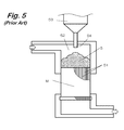
- Fig. 5 shows a coating device by the existent wash coat method, in which a slurry S is supplied from a slurry supplying device 53 to a storing part 52 formed on the side of the upper end of a monolith M disposed such that honeycomb channels 51 --- are opened at upper and lower ends, and the slurry is caused to flow into and spread in the flow channels 51 by supplying a pressurized air on the side of the upper end or sucking air on the side of the lower end to coat the inner wall of the channels 51.
- a noble metal such as platinum is sometimes contained in the slurry S and the slurry S by a necessary amount used for coating the monolith M to the storing part 52.
- the slurry supply nozzle 54 is necessary to have a diameter to some extent but it is desirably as small as possible for strictly controlling the supply amount. Then, when a slurry at a high viscosity is supplied from the supply nozzle 54 to the storing part 52, the slurry S is stored in a state raised at a portion just beneath the supply nozzle 54 (refer to Fig. 6(a) ).
- the slurry S When a pressurized air is supplied from the upper end or air is sucked from the lower end in this state, the slurry S initially flows inward uniformly in each of the channels 51 --- (refer to Fig. 6(b) ). Since the amount of the slurry S is large in the central portion and small in the peripheral portion, even after the slurry S at the peripheral portion has been caused to flow downward completely into the honeycomb channels 51A at the peripheral portion, the slurry still flows downward in the honeycomb channels 51B at the central portion.
- the coating length for the honeycomb channels 51B in the central part is longer than the coating length in the honeycomb channels 51A at the peripheral part (refer to Fig. 6(c) ).
- the honeycomb channels 51A at the peripheral part are coated only by the one-half length or less, whereas the honeycomb channels 51B at the central part are coated by one-half length or more to make the coating length not uniform.
- a slurry when supplied by a necessary amount used for coating with no excess of insufficiency, it can be coated uniformly with no wasteful loss for any of the channels formed in the substrate.
- the present invention provides a substrate coating device by spreading a slurry supplied on one end of a substrate in which a plurality of flow channels are formed in parallel with each other in the flow channels by an air pressure thereby coating the inner wall of the flow channels, including the slurry supplying device for supplying a slurry by a necessary amount to a slurry storing part formed above the upper surface of the substrate in which both ends of the channels are opened at the upper surface and the bottom surface, and a liquid surface levelling mechanism for levelling the liquid surface of the slurry before spreading the slurry into the flow channels.
- the slurry is supplied by a necessary amount from the slurry supplying device to the slurry storing part formed above the upper surface of the substrate in which the flow channels are arranged such that the both ends thereof are opened to the upper surface and the bottom surface, the liquid surface of the slurry is levelled by the liquid surface levelling mechanism and then the slurry is spread in the flow channels. That is, the slurry supplied from the slurry supplying device is raised at the instance in a convex shape in the slurry storing part but the slurry liquid surface is levelled before spreading the slurry into the flow channels by the liquid surface levelling mechanism, for example, by rotating the substrate around a vertical axis passing therethrough, or vibrating the stored slurry.
- the slurry in a case of intending to coat the slurry, for example, over the entire length for each of the channels, even when the slurry is supplied by a just mount necessary for use in coating to the storing part, since an appropriate amount of the slurry is caused to flow into and spread in each of the channels, the slurry can be coated over the entire length for each of the channels.
- an air pressure control mechanism may be provided for switching inhibition of the inflow or extension of the slurry into the flow channel by controlling the gravitational force of the slurry tending to flow from the slurry storing part to each of the channels and the air pressure in the flow channels such that the slurry does not flow into each of the channels before levelling the liquid surface.
- an air handling device of supplying/sucking air on the side of the bottom of the substrate to exert a positive pressure/negative pressure into each of the channels is used as described in claim 5, or an air handling device having a detachable packing for tightly sealing the channel opening on the side of the bottom of the substrate and sucking air in the flow channel and/or supplying a pressurized air on the side of the liquid surface of the slurry storing part in a state of opening the packing is used.
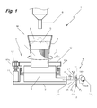
- Fig. 1 is an explanatory view showing an example of a substrate coating device according to the invention
- Fig. 2 is a step chart showing an example of a substrate coating method according to the invention
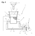
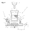
- Fig. 3 and Fig. 4 are explanatory views showing other embodiments.
- the substrate coating device 1 shown in Fig. 1 is used for flowing and spreading a catalyst slurry S by an air pressure into a plurality of honeycomb channels 2--- formed in parallel with each other in a monolith (catalyst substrate) M and coating the inner wall 2w of the honeycomb flow channels thereby manufacturing an exhaust gas purifying catalyst.
- the substrate coating device 1 includes a device main body 3 for fixing a monolith M such that both ends of the honeycomb channels 2 --- are opened to the upper surface and the bottom surface, a slurry supplying device 6 for supplying a slurry S by a necessary amount to a slurry storing part 5 in which an attachment 4 is mounted to the upper end of the monolith M, a liquid surface levelling mechanism 7 for levelling the liquid surface of the slurry, and an air pressure control mechanism 8 for controlling the gravitational force of the slurry S tending to flow into each of the flow channels 2 --- from the slurry storing part 5 and the air pressure in the flow channels 2 --- thereby switching the inhibition of inflow and spreading of the slurry S to the flow channels 2 ---.
- the ceiling surface of an air chamber 9 controlled for the inner pressure by the air pressure control mechanism 8 is formed with a rotary table (substrate rotational mechanism) 10 capable of rotationally supporting the monolith M.
- the rotary table 10 is adapted such that the monolith M can be mounted rotationally around a vertical axis passing therethrough by meshing between gear teeth 10a formed to the outer peripheral surface thereof and gear teeth 12a of a drive gear 12 driven by a motor 11, to constitute a liquid surface levelling mechanism 7 for levelling the liquid surface of the slurry by utilizing a centrifugal force by rotation in a state of storing the slurry S in the slurry storing part 5.
- the monolith M is fixed being fitted into a perforation hole 10b formed in the rotary table 10 such that the honeycomb channels 2 --- are opened at the upper end to the outside of the air chamber 9 and opened at the lower end into the air chamber 9.
- the attachment 4 as the slurry storing 5 is fitted at the lower end thereof which is formed in a shape and a size identical with those of the upper end surface of the monolith M and formed as a frust conical plane gradually expanded toward the upper end thereof.
- the slurry supplying device 6 is set such that the slurry S of a predetermined amount is accurately measured and supplied.
- the air pressure control mechanism 8 uses an air handling device 13 for supplying/sucking air thereby exerting positive pressure/negative pressure into each of the channels 2 --- and, more specifically, includes an air pump 14 for sucking and discharging air and a switching valve CV for switching supply/suction of air to the air chamber 9.
- the switching valve CV comprises a 3-position valve for switchingly connecting a suction side 14in and a discharge side 14out of the air pump 14 to an atmospheric air opening port 15 and a supply/exhaust pipe 16, and is adapted to supply air sucked from the atmospheric air opening port 15 into the air chamber 9 to exert a positive pressure to the flow channels 2 --- at first portion P1, shut the supply/exhaust pipe 16 at a second position P 2 , maintain the inner pressure of the air chamber 9, and forcively discharge air in the air chamber 9 to exert a negative pressure on the flow channels 2 --- at a third position P 3 .
- a relief valve 18 is intervened in a pipeline 17 branched from the supply/discharge pipe 16 and adapted to be opened when the inner pressure of the air chamber 9 exceeds a set pressure to release the inner air and keep the inner pressure to the set pressure.
- the slurry S filled in each of the channels 2 --- is spread along the inner wall 2w of the channel and, since the slurry S has been initially supplied by a necessary minimum amount that can coat the entire length of all the honeycomb channels 2 ---, the entire length is coated equally both in the honeycomb channels 2A for the peripheral part and the honeycomb channels 2B for the central part of the monolith M as shown in Fig. 2(e) .
- This is not restricted restrict to a case of coating the entire length and, for example, in a case of coating a predetermined length such as 1/2 or 2/3 for the entire length, the supply amount of slurry to the slurry storing part 5 may be adjusted in accordance with the coating length.
- Fig. 3 shows another embodiment of the invention.
- a centrifugal force is not exerted but vibrations are exerted.
- Portions identical with those in Fig. 1 carry identical references for which detailed descriptions are to be omitted.
- a table 23 for fixing a monolith M such that both ends of the honeycomb channels 2 --- are opened to the upper surface and the bottom surface is disposed to the ceiling surface of the device main body 22 provided with an air chamber 9 in which the inner pressure is controlled by a air pressure control mechanism 8.
- a liquid surface levelling mechanism 7 includes a vibrator (vibration mechanism) 24 attached to the outer peripheral surface of an attachment 4 mounted to the upper end of the monolith M, so that the liquid surface of the slurry S stored in a convexed state is levelled for the by vibration, for example, by low frequency oscillation, high frequency oscillation, and ultrasonic oscillation.
- the vibrator 24 may be attached to the device main body 22 and, in summary, it may be adapted such that vibrations are transmitted to the slurry S stored in the slurry storing part 5.
- FIG. 4 shows a further embodiment.
- air pressure can be controlled without supplying air to the honeycomb channels 2 ---.
- Portions common with those in Fig. 1 carry identical references for which detailed descriptions are to be omitted.
- a substrate coating device 31 in this embodiment uses an air handling device 34 having a detachable packing 32 that tightly seals the opening of the honeycomb channels 2 --- on the side of the bottom, and an air pump 33 for sucking air in the honeycomb channels 2 --- by way of an air chamber 9 in a state of opening the packing 32 as an air pressure control mechanism 8.
- a lift base 35 disposed vertically movably in the air chamber 9 is attached rotationally to a lifting shaft 36, and a soft rubber 38 is disposed by way of a sponge-like elastic member 37 on the surface of the base 35, to tightly seal the opening of the honeycomb channel 2 --- by the soft rubber 38.
- the invention is not restricted only thereto but it may be applied to the case of supplying the pressurized air on the side of the liquid surface of the slurry storing part 5, or to a case of conducting both of them.
- description has been made to the case of coating the catalyst slurry to the monolith M as the catalyst substrate the invention is not restricted thereto but is applicable to various uses providing that the slurry is coated to the inner walls of a plurality of flow channels formed in parallel with each other to a substrate.
- the slurry since the slurry is caused to flow into each of the flow channels after the liquid surface of the slurry supplied in the slurry storing part is levelled, it can provide an excellent effect that a slurry of an identical amount flows into each of the flow channels and the slurry can coat uniformly for the identical length in each of the channels and also provide an excellent effect of not resulting in the wasteful loss of the slurry even in a case of coating the slurry over the entire length of the flow channels.
- the invention can be applied to the use of spreading a slurry in a plurality of the channels formed in parallel with each other to a substrate and coating the inner wall of the flow channels and this is particularly suitable to the application use of forming a catalyst by coating a catalyst slurry to the inner wall of honeycomb channels formed in the monolith as a catalyst substrate for an exhaust gas purifying catalyst.
Landscapes
- Chemical & Material Sciences (AREA)
- Engineering & Computer Science (AREA)
- Materials Engineering (AREA)
- Organic Chemistry (AREA)
- Chemical Kinetics & Catalysis (AREA)
- Catalysts (AREA)
- Application Of Or Painting With Fluid Materials (AREA)
Abstract
Description
- The present invention concerns a device and a method for coating a substrate by spreading a slurry in a plurality of flow channels formed in parallel with each other to a substrate and coating the inner wall of the flow channels thereof and it is particularly suitable to coating of a catalyst slurry to the inner wall of a honeycomb channel formed to a monolith as a catalyst substrate for an exhaust gas purifying catalyst to form a catalyst.
- A wash coat method has been known as a method of coating a catalyst slurry on the inner wall of the honeycomb channels formed to a monolith as a catalyst substrate.
- Patent Document 1:
JP-A No. 63-51949 - Patent Document 2:
JP-W 2002-506720 -
Fig. 5 shows a coating device by the existent wash coat method, in which a slurry S is supplied from aslurry supplying device 53 to astoring part 52 formed on the side of the upper end of a monolith M disposed such thathoneycomb channels 51 --- are opened at upper and lower ends, and the slurry is caused to flow into and spread in theflow channels 51 by supplying a pressurized air on the side of the upper end or sucking air on the side of the lower end to coat the inner wall of thechannels 51.
Recently, a noble metal such as platinum is sometimes contained in the slurry S and the slurry S by a necessary amount used for coating the monolith M to thestoring part 52. - By the way, since some slurry S has a high viscosity, the
slurry supply nozzle 54 is necessary to have a diameter to some extent but it is desirably as small as possible for strictly controlling the supply amount. Then, when a slurry at a high viscosity is supplied from thesupply nozzle 54 to thestoring part 52, the slurry S is stored in a state raised at a portion just beneath the supply nozzle 54 (refer toFig. 6(a) ). - When a pressurized air is supplied from the upper end or air is sucked from the lower end in this state, the slurry S initially flows inward uniformly in each of the
channels 51 --- (refer toFig. 6(b) ).
Since the amount of the slurry S is large in the central portion and small in the peripheral portion, even after the slurry S at the peripheral portion has been caused to flow downward completely into thehoneycomb channels 51A at the peripheral portion, the slurry still flows downward in thehoneycomb channels 51B at the central portion. - Then, when the slurry is finally spread and coated in the
honeycomb channels 51 by sucking air on the side of the lower end, the coating length for thehoneycomb channels 51B in the central part is longer than the coating length in thehoneycomb channels 51A at the peripheral part (refer toFig. 6(c) ). - Accordingly, in a case, for example, of supplying a slurry in a required amount intending to coat the slurry S by one-half length of the
honeycomb channels 51, thehoneycomb channels 51A at the peripheral part are coated only by the one-half length or less, whereas thehoneycomb channels 51B at the central part are coated by one-half length or more to make the coating length not uniform.
In the same manner, in a case of supplying the slurry S by a necessary amount used for coating the monolith M, since a sufficient amount of the slurry S does not flow downward in thehoneycomb channels 51A at the peripheral part, thehoneycomb channels 51A are not coated as far as the lower end, whereas excess slurry S flows out from thehoneycomb channels 51B at the central part (refer to Fig. (d)). - Accordingly, in order to coat the slurry S uniformly over the entire length for each of the
honeycomb channels 51, it has to be used inevitably a method of supplying the slurry S in a much more amount than the necessary amount used for coating the monolith M to the storingpart 52, filling the slurry S excessively in all thehoneycomb channels 51 and cleaning off the surplus slurry S. Then, the cleaned off surplus slurry S has to be recovered, reconditioned for the ingredient and recycled, and this results in troubles by so much. - In view of the above, it is a technical subject of the present invention that a slurry, when supplied by a necessary amount used for coating with no excess of insufficiency, it can be coated uniformly with no wasteful loss for any of the channels formed in the substrate.
- The present invention provides a substrate coating device by spreading a slurry supplied on one end of a substrate in which a plurality of flow channels are formed in parallel with each other in the flow channels by an air pressure thereby coating the inner wall of the flow channels, including the slurry supplying device for supplying a slurry by a necessary amount to a slurry storing part formed above the upper surface of the substrate in which both ends of the channels are opened at the upper surface and the bottom surface, and a liquid surface levelling mechanism for levelling the liquid surface of the slurry before spreading the slurry into the flow channels.
- According to the substrate coating device of the invention, the slurry is supplied by a necessary amount from the slurry supplying device to the slurry storing part formed above the upper surface of the substrate in which the flow channels are arranged such that the both ends thereof are opened to the upper surface and the bottom surface, the liquid surface of the slurry is levelled by the liquid surface levelling mechanism and then the slurry is spread in the flow channels.
That is, the slurry supplied from the slurry supplying device is raised at the instance in a convex shape in the slurry storing part but the slurry liquid surface is levelled before spreading the slurry into the flow channels by the liquid surface levelling mechanism, for example, by rotating the substrate around a vertical axis passing therethrough, or vibrating the stored slurry. - As described above, after the liquid surface is levelled in the storing part, when the slurry is caused to flow to the respective channels by acting a pressurized air from the upper end or sucking air from the lower end and, optionally, conducting pressurization and sucking at the same time, since the positions for the liquid surface to the respective channels are equal at that time, an identical amount of slurry is caused to flow into each of the channels.
Accordingly, in a case of intending to coat the slurry, for example, over the entire length for each of the channels, even when the slurry is supplied by a just mount necessary for use in coating to the storing part, since an appropriate amount of the slurry is caused to flow into and spread in each of the channels, the slurry can be coated over the entire length for each of the channels. - Further, while a slurry generally has such an extent of viscosity as not flowing into the channels as it is, some slurry has a low viscosity to such an extent as flowing into the flow channels only by the gravitational force.
In a case of using such a slurry, as described inclaim 4, an air pressure control mechanism may be provided for switching inhibition of the inflow or extension of the slurry into the flow channel by controlling the gravitational force of the slurry tending to flow from the slurry storing part to each of the channels and the air pressure in the flow channels such that the slurry does not flow into each of the channels before levelling the liquid surface. - As the air pressure control mechanism, an air handling device of supplying/sucking air on the side of the bottom of the substrate to exert a positive pressure/negative pressure into each of the channels is used as described in
claim 5, or an air handling device having a detachable packing for tightly sealing the channel opening on the side of the bottom of the substrate and sucking air in the flow channel and/or supplying a pressurized air on the side of the liquid surface of the slurry storing part in a state of opening the packing is used. - In this embodiment, a subject for enabling to flow a slurry at a high viscosity uniformly with no waste to any of the channels and conducting coating has been attained by a simple constitution.
-
Fig. 1 is an explanatory view showing an example of a substrate coating device according to the invention,Fig. 2 is a step chart showing an example of a substrate coating method according to the invention, andFig. 3 andFig. 4 are explanatory views showing other embodiments. - The
substrate coating device 1 shown inFig. 1 is used for flowing and spreading a catalyst slurry S by an air pressure into a plurality ofhoneycomb channels 2--- formed in parallel with each other in a monolith (catalyst substrate) M and coating theinner wall 2w of the honeycomb flow channels thereby manufacturing an exhaust gas purifying catalyst. - The
substrate coating device 1 includes a device main body 3 for fixing a monolith M such that both ends of thehoneycomb channels 2 --- are opened to the upper surface and the bottom surface, aslurry supplying device 6 for supplying a slurry S by a necessary amount to aslurry storing part 5 in which anattachment 4 is mounted to the upper end of the monolith M, a liquidsurface levelling mechanism 7 for levelling the liquid surface of the slurry, and an air pressure control mechanism 8 for controlling the gravitational force of the slurry S tending to flow into each of theflow channels 2 --- from theslurry storing part 5 and the air pressure in theflow channels 2 --- thereby switching the inhibition of inflow and spreading of the slurry S to theflow channels 2 ---. - In the device main body 3, the ceiling surface of an air chamber 9 controlled for the inner pressure by the air pressure control mechanism 8 is formed with a rotary table (substrate rotational mechanism) 10 capable of rotationally supporting the monolith M.
The rotary table 10 is adapted such that the monolith M can be mounted rotationally around a vertical axis passing therethrough by meshing betweengear teeth 10a formed to the outer peripheral surface thereof andgear teeth 12a of adrive gear 12 driven by amotor 11, to constitute a liquidsurface levelling mechanism 7 for levelling the liquid surface of the slurry by utilizing a centrifugal force by rotation in a state of storing the slurry S in theslurry storing part 5.
The monolith M is fixed being fitted into aperforation hole 10b formed in the rotary table 10 such that thehoneycomb channels 2 --- are opened at the upper end to the outside of the air chamber 9 and opened at the lower end into the air chamber 9. - The
attachment 4 as theslurry storing 5 is fitted at the lower end thereof which is formed in a shape and a size identical with those of the upper end surface of the monolith M and formed as a frust conical plane gradually expanded toward the upper end thereof.
Theslurry supplying device 6 is set such that the slurry S of a predetermined amount is accurately measured and supplied. - The air pressure control mechanism 8 uses an
air handling device 13 for supplying/sucking air thereby exerting positive pressure/negative pressure into each of thechannels 2 --- and, more specifically, includes anair pump 14 for sucking and discharging air and a switching valve CV for switching supply/suction of air to the air chamber 9. - Then, the switching valve CV comprises a 3-position valve for switchingly connecting a suction side 14in and a discharge side 14out of the
air pump 14 to an atmosphericair opening port 15 and a supply/exhaust pipe 16, and is adapted to supply air sucked from the atmosphericair opening port 15 into the air chamber 9 to exert a positive pressure to theflow channels 2 --- at first portion P1, shut the supply/exhaust pipe 16 at a second position P2, maintain the inner pressure of the air chamber 9, and forcively discharge air in the air chamber 9 to exert a negative pressure on theflow channels 2 --- at a third position P3.
Further, arelief valve 18 is intervened in apipeline 17 branched from the supply/discharge pipe 16 and adapted to be opened when the inner pressure of the air chamber 9 exceeds a set pressure to release the inner air and keep the inner pressure to the set pressure. - An example of the constitution of the invention is as has been described above, and description is to be made to a case of coating a slurry to the catalyst substrate by a substrate coating method according to the invention.
At first, in a state of mounting theattachment 4 to the monolith M as the catalyst substrate, this is fixed to the rotary table 10.
In the slurry supply step as shown inFig. 2(a) , the slurry S by a necessary minimum amount used upon coating the slurry S over the entire length of thehoneycomb channels 2 --- is supplied from theslurry supplying device 6 to theslurry storing part 5. Since the slurry S has a viscosity to some extent, it is in a state raised in theslurry storing part 5.
Simultaneously, when the switching valve CV of the air pressure control mechanism 8 is set to the first position P1, air is supplied into the air chamber 9 to exert a positive pressure to each of thechannels 2 --- to such an extent as the slurry S does not flow into thehoneycomb channels 2 --- and then the switching valve CV is set to the second position P2, a positive pressure in each of thechannels 2 --- is maintained even when theair pump 14 is stopped. - Then, in the liquid surface levelling step, as shown in
Fig. 2(b) , when the rotary table 10 of the liquidsurface levelling mechanism 7 is rotated at an appropriate number of rotation, the monolith M and theattachment 4 mounted to the upper end thereof are rotated, in which a centrifugal force exerts on the slurry S stored in theslurry storing part 5 and the slurry S raised in the central part extends to the periphery.
Then, at the instance the liquid surface is levelled, substantially, the rotation of the rotary table 10 is stopped.
Meanwhile, since the inside of thehoneycomb channels 2 --- is kept at the positive pressure, the slurry S does not flow inward. - Then, in the slurry spreading step, air in the air chamber 9 is sucked by setting the switching valve CV of the air pressure control mechanism 8 to the third position P3 to flow the slurry S into the honeycomb channels 2as shown in
Fig. 2(c) .
In this instance, since the liquid surface is uniform (horizontal), the slurry S flows equally to each of thechannels 2 --- and, when all the slurry S stored in thestoring part 5 flow into each of the channels, the slurry S is filled in each of thechannels 2 --- each for an identical length as shown inFig. 2(d) . - Further, when air in the air chamber 9 is sucked, the slurry S filled in each of the
channels 2 --- is spread along theinner wall 2w of the channel and, since the slurry S has been initially supplied by a necessary minimum amount that can coat the entire length of all thehoneycomb channels 2 ---, the entire length is coated equally both in thehoneycomb channels 2A for the peripheral part and thehoneycomb channels 2B for the central part of the monolith M as shown inFig. 2(e) .
This is not restricted restrict to a case of coating the entire length and, for example, in a case of coating a predetermined length such as 1/2 or 2/3 for the entire length, the supply amount of slurry to theslurry storing part 5 may be adjusted in accordance with the coating length. -
Fig. 3 shows another embodiment of the invention. In this embodiment, upon levelling the liquid surface of slurry, a centrifugal force is not exerted but vibrations are exerted. Portions identical with those inFig. 1 carry identical references for which detailed descriptions are to be omitted.
In asubstrate coating device 21 of this embodiment, a table 23 for fixing a monolith M such that both ends of thehoneycomb channels 2 --- are opened to the upper surface and the bottom surface is disposed to the ceiling surface of the devicemain body 22 provided with an air chamber 9 in which the inner pressure is controlled by a air pressure control mechanism 8.
A liquidsurface levelling mechanism 7 includes a vibrator (vibration mechanism) 24 attached to the outer peripheral surface of anattachment 4 mounted to the upper end of the monolith M, so that the liquid surface of the slurry S stored in a convexed state is levelled for the by vibration, for example, by low frequency oscillation, high frequency oscillation, and ultrasonic oscillation.
Thevibrator 24 may be attached to the devicemain body 22 and, in summary, it may be adapted such that vibrations are transmitted to the slurry S stored in theslurry storing part 5. -
Fig. 4 shows a further embodiment. In this embodiment, air pressure can be controlled without supplying air to thehoneycomb channels 2 ---. Portions common with those inFig. 1 carry identical references for which detailed descriptions are to be omitted.
Asubstrate coating device 31 in this embodiment uses anair handling device 34 having adetachable packing 32 that tightly seals the opening of thehoneycomb channels 2 --- on the side of the bottom, and anair pump 33 for sucking air in thehoneycomb channels 2 --- by way of an air chamber 9 in a state of opening thepacking 32 as an air pressure control mechanism 8.
To thepacking 32, alift base 35 disposed vertically movably in the air chamber 9 is attached rotationally to alifting shaft 36, and asoft rubber 38 is disposed by way of a sponge-likeelastic member 37 on the surface of thebase 35, to tightly seal the opening of thehoneycomb channel 2 --- by thesoft rubber 38. - With the constitution, when the packing 32 is in intimate contact with the monolith M to close the opening on the bottom of the
flow channel 2 in the slurry supply step and the liquid surface levelling step, even when the slurry supplied in theslurry storing part 5 tends to flow into thehoneycomb channels 2---, inflow of the slurry S is reliably inhibited by the pressure of air confined in each of thechannels 2. - Then, in the slurry spreading step, when the
air pump 33 of theair handling device 34 is actuated after lowering the packing 32, air in thehoneycomb channels 2 is sucked by way of the air chamber 9 and the slurry S flows uniformly to each of thehoneycomb channels 2 - Further, in the foregoings, while description has been made to a case of sucking air in the
honeycomb channels 2 --- by way of the air chamber 9 using theair handling device slurry storing part 5, or to a case of conducting both of them.
Further, while description has been made to the case of coating the catalyst slurry to the monolith M as the catalyst substrate, the invention is not restricted thereto but is applicable to various uses providing that the slurry is coated to the inner walls of a plurality of flow channels formed in parallel with each other to a substrate. - As has been described above according to the invention, since the slurry is caused to flow into each of the flow channels after the liquid surface of the slurry supplied in the slurry storing part is levelled, it can provide an excellent effect that a slurry of an identical amount flows into each of the flow channels and the slurry can coat uniformly for the identical length in each of the channels and also provide an excellent effect of not resulting in the wasteful loss of the slurry even in a case of coating the slurry over the entire length of the flow channels.
- The invention can be applied to the use of spreading a slurry in a plurality of the channels formed in parallel with each other to a substrate and coating the inner wall of the flow channels and this is particularly suitable to the application use of forming a catalyst by coating a catalyst slurry to the inner wall of honeycomb channels formed in the monolith as a catalyst substrate for an exhaust gas purifying catalyst.
-
- [
Fig. 1 ] is an explanatory view showing an example of a substrate coating device according to the invention. - [
Fig. 2 ] is an explanatory view showing an example of a substrate coating method according to the invention. - [
Fig. 3 ] is an explanatory view showing another embodiment. - [
Fig. 4 ] is an explanatory view showing a further embodiment. - [
Fig. 5 ] is an explanatory view showing an existent device. - [
Fig. 6 ] is an explanatory view showing an existent method. -
- 1
- Substrate coating device
- M
- Monolith (catalyst substrate)
- S
- Catalyst slurry
- 2
- Honeycomb channel
- 2w
- Channel inner wall
- 3
- Device main body
- 4
- Attachment
- 5
- Slurry storing part
- 6
- Slurry supplying device
- 7
- Liquid surface levelling mechanism
- 8
- Air pressure control mechanism
- 9
- Air chamber
- 10
- Rotary table (substrate rotating mechanism)
- 13
- Air handling device
Claims (9)
- A substrate coating device of spreading a slurry supplied on one side of a substrate formed with a plurality of flow channels in parallel with each other into the flow channels by an air pressure thereby coating the inner wall of the flow channels including:a slurry supplying device for supplying a slurry by a necessary amount to a slurry storing part formed above the upper surface of a substrate disposed such that both ends of the channels are opened to the upper surface and the bottom surface, and a liquid surface leveling mechanism for making the slurry liquid surface uniform before spreading the slurry in the flow channels.
- A substrate coating device according to claim 1, wherein the liquid surface levelling mechanism is a substrate rotating mechanism for rotating the substrate around a vertical axis passing therethrough.
- A substrate coating device according to claim 1, wherein the liquid surface levelling mechanism is a vibration mechanism for vibrating the slurry stored in the slurry storing part.
- A substrate coating device according to claim 1, having an air pressure control mechanism for controlling a gravitational force of the slurry tending to flow from the slurry storing part into each of the flow channels and an air pressure in the channels to switch the inhibition of inflow and spreading of the slurry in the flow channels.
- A substrate coating device according to claim 4, wherein an air handling device for supplying/sucking air on the side of the bottom of the substrate to exert a positive pressure and/or negative pressure in each of the flow channels is used as the air pressure control mechanism.
- A substrate coating device according to claim 4, wherein an air handling device having a detachable packing for tightly sealing the opening of the channels on the side of the bottom of the substrate and for sucking air in the channels and/or supplying a pressurized air on the side of the liquid surface of the slurry storing part in a state of opening the packing is used as the air pressure control mechanism.
- A substrate coating method of spreading a slurry supplied on one end of a substrate formed with a plurality of channels in parallel with each other into the channels by an air pressure and coating the inner wall of the flow channels, including:a slurry supply step of supplying a necessary amount of slurry to a slurry storing part formed at the upper surface of a substrate in which both ends of the channels are disposed so as to open to the upper surface and the bottom surface, and a liquid surface levelling step for levelling the liquid surface of the slurry before spreading the slurry in the flow channel.
- A substrate coating method according to claim 7, wherein the gravitational force of the slurry tending to flow from the slurry storing part into each of the flow channels and an air pressure in the flow channels are kept in a balanced state in the slurry supply step and the liquid surface levelling step.
- A substrate coating method according to claim 7, wherein a catalyst slurry is coated to the inner wall of the flow channels of the catalyst substrate to form a catalyst by using a catalyst substrate formed with a plurality of channels in parallel with each other as the substrate, and using the catalyst slurry as the slurry.
Applications Claiming Priority (1)
| Application Number | Priority Date | Filing Date | Title |
|---|---|---|---|
| PCT/JP2005/012555 WO2007007370A1 (en) | 2005-07-07 | 2005-07-07 | Device and method for coating base material |
Publications (3)
| Publication Number | Publication Date |
|---|---|
| EP1900442A1 true EP1900442A1 (en) | 2008-03-19 |
| EP1900442A4 EP1900442A4 (en) | 2010-11-10 |
| EP1900442B1 EP1900442B1 (en) | 2013-01-09 |
Family
ID=37636778
Family Applications (1)
| Application Number | Title | Priority Date | Filing Date |
|---|---|---|---|
| EP05758332A Expired - Lifetime EP1900442B1 (en) | 2005-07-07 | 2005-07-07 | Device and method for coating base material |
Country Status (4)
| Country | Link |
|---|---|
| US (1) | US8302557B2 (en) |
| EP (1) | EP1900442B1 (en) |
| CN (1) | CN101218039B (en) |
| WO (1) | WO2007007370A1 (en) |
Cited By (16)
| Publication number | Priority date | Publication date | Assignee | Title |
|---|---|---|---|---|
| US20120021896A1 (en) * | 2009-04-03 | 2012-01-26 | Atsushi Nakano | Method and apparatus of manufacturing exhaust gas-purifying catalyst and nozzle used therefor |
| RU2488450C2 (en) * | 2010-04-27 | 2013-07-27 | Борис Владимирович Скворцов | Application of coat onto pipe inner surface |
| RU2503506C2 (en) * | 2011-12-29 | 2014-01-10 | Общество с ограниченной ответственностью "Аналитические приборы и системы" | System of automatic control over application of insulating coat on cylindrical article inner surface |
| RU2551518C1 (en) * | 2014-03-04 | 2015-05-27 | Федеральное государственное бюджетное образовательное учреждение высшего профессионального образования "Самарский государственный аэрокосмический университет имени академика С.П. Королева (национальный исследовательский университет)" (СГАУ) | Method to apply coating on internal surface of cylindrical items |
| WO2016083748A3 (en) * | 2014-11-26 | 2016-09-01 | Glass Surface Technology | Method and device for coating the inner surface of a container and container obtained with such a method |
| RU2656664C1 (en) * | 2017-07-11 | 2018-06-06 | федеральное государственное автономное образовательное учреждение высшего образования "Самарский национальный исследовательский университет имени академика С.П. Королёва" | Method of application of insulating coatings to internal pipe surface |
| EP3424595A1 (en) | 2017-07-06 | 2019-01-09 | Umicore Ag & Co. Kg | Coating apparatus and method |
| DE102017115138A1 (en) | 2017-07-06 | 2019-01-10 | Umicore Ag & Co. Kg | Contactless leveling of a washcoat suspension |
| RU189001U1 (en) * | 2018-11-12 | 2019-05-06 | федеральное государственное автономное образовательное учреждение высшего образования "Самарский национальный исследовательский университет имени академика С.П. Королева" | Device for applying insulating coatings on the inner surface of the pipe |
| RU198609U1 (en) * | 2020-03-16 | 2020-07-20 | федеральное государственное автономное образовательное учреждение высшего образования "Самарский национальный исследовательский университет имени академика С.П. Королева" | DEVICE TO CONTROL THE APPLICATION OF PROTECTIVE COATINGS ON THE INNER SURFACE OF PRODUCTS OF CYLINDRICAL SHAPE |
| WO2020165387A1 (en) | 2019-02-14 | 2020-08-20 | Umicore Ag & Co. Kg | Method for producing motor vehicle exhaust gas catalysts |
| DE202021103624U1 (en) | 2021-07-06 | 2022-10-14 | Umicore Ag & Co. Kg | WC applicator |
| DE202023100970U1 (en) | 2023-03-01 | 2023-03-16 | Umicore Ag & Co. Kg | coating device |
| DE202021106828U1 (en) | 2021-12-15 | 2023-03-24 | Umicore Ag & Co. Kg | coating chamber |
| EP4299194A1 (en) | 2022-06-29 | 2024-01-03 | Umicore AG & Co. KG | Coating apparatus |
| WO2024041907A1 (en) | 2022-08-25 | 2024-02-29 | Umicore Ag & Co. Kg | Applicator for applying coating medium to substrates |
Families Citing this family (30)
| Publication number | Priority date | Publication date | Assignee | Title |
|---|---|---|---|---|
| US8006637B2 (en) * | 2007-03-29 | 2011-08-30 | Corning Incorporated | Method and apparatus for membrane deposition |
| JP2010017666A (en) * | 2008-07-11 | 2010-01-28 | Tokyo Roki Co Ltd | Catalyst for purifying exhaust gas |
| JP5742080B2 (en) * | 2011-03-16 | 2015-07-01 | セメダイン株式会社 | Coating device |
| JP5925101B2 (en) * | 2012-10-09 | 2016-05-25 | 株式会社キャタラー | Slurry supply nozzle and exhaust gas purifying catalyst manufacturing apparatus and manufacturing method using the same |
| CN102942181B (en) * | 2012-12-04 | 2014-07-02 | 南京大学 | Preparation method of formed carbon-based material |
| DE102013104318A1 (en) * | 2013-04-29 | 2014-10-30 | Fredy Iseli | Coating device and coating method |
| CN104259057B (en) * | 2014-09-18 | 2016-08-17 | 中国建筑材料科学研究总院 | Vacuum is coated with cream equipment |
| CN104384075A (en) * | 2014-12-19 | 2015-03-04 | 济南洁瑞热能科技有限公司 | Novel grouting equipment for inner wall of enamel pipe of air preheater |
| JP6546758B2 (en) * | 2015-03-09 | 2019-07-17 | 株式会社キャタラー | Catalyst slurry coating system |
| EP3277424A4 (en) * | 2015-03-30 | 2019-05-01 | BASF Corporation | MULTIFUNCTIONAL COATING SYSTEM AND LAVIS CATALYTIC LAYER APPLICATION COATING MODULE AND / OR SOLUTION TO SUBSTRATE AND ASSOCIATED METHODS |
| CN112121869A (en) | 2015-10-02 | 2020-12-25 | 托普索公司 | Preparation method of catalyst-containing ceramic filter for exhaust gas or exhaust gas purification |
| CN105537057A (en) * | 2016-02-05 | 2016-05-04 | 江苏三杰新能源有限公司 | Homogenizer for battery coating material |
| JP6244421B1 (en) * | 2016-07-27 | 2017-12-06 | 株式会社キャタラー | Exhaust gas purification catalyst manufacturing method and manufacturing apparatus |
| CN109789357B (en) * | 2016-09-30 | 2021-06-29 | 日立金属株式会社 | Method and apparatus for manufacturing ceramic honeycomb filter |
| EP3323497B1 (en) | 2016-11-16 | 2019-05-22 | Umicore AG & Co. KG | Coated catalyst |
| JP6403931B1 (en) * | 2017-03-31 | 2018-10-10 | 株式会社キャタラー | Method for manufacturing exhaust gas purification device |
| EP3424596A1 (en) | 2017-07-06 | 2019-01-09 | Umicore Ag & Co. Kg | Method for coating a monolith carrier |
| CN107519943B (en) * | 2017-08-16 | 2020-07-14 | 柳州申通汽车科技有限公司 | Method for treating catalyst slurry for automobile |
| CN107876300A (en) * | 2017-12-12 | 2018-04-06 | 杭州凯明催化剂股份有限公司 | A kind of VOCs purifications irregular honeycomb ceramic carrier catalyst coating unit and its application method |
| GB201819455D0 (en) * | 2018-11-29 | 2019-01-16 | Johnson Matthey Plc | Apparatus and method for coating substrates with washcoats |
| JP6698809B1 (en) * | 2018-12-19 | 2020-05-27 | 株式会社キャタラー | Exhaust gas purification device manufacturing method |
| CN109967311A (en) * | 2019-03-13 | 2019-07-05 | 俞利祥 | A kind of Rustproofing apparatus of concrete punching block |
| CN109935966B (en) * | 2019-03-19 | 2021-04-09 | 北京遥感设备研究所 | Large-size and large-mass antenna housing reinforcing method |
| CN110711682B (en) * | 2019-10-18 | 2023-10-03 | 浙江达峰汽车技术有限公司 | Gasoline engine particulate matter filters carrier catalyst coating device |
| CN111361875A (en) * | 2020-03-16 | 2020-07-03 | 巨泽明 | Auxiliary device for injecting viscous liquid |
| JP7247381B1 (en) | 2022-01-07 | 2023-03-28 | 株式会社キャタラー | Equipment for manufacturing exhaust gas purification catalysts |
| DE202022000455U1 (en) | 2022-02-22 | 2022-03-02 | Umicore Ag & Co. Kg | coating hat |
| DE202023103234U1 (en) | 2023-06-13 | 2023-06-26 | Umicore Ag & Co. Kg | coating device |
| CN121124478A (en) * | 2025-11-13 | 2025-12-12 | 和骋新材料科技(上海)有限公司 | Liquid coating equipment and coating methods |
| CN121082509A (en) * | 2025-11-13 | 2025-12-09 | 和骋新材料科技(上海)有限公司 | Liquid coating apparatus, method and motor manufacturing method |
Family Cites Families (14)
| Publication number | Priority date | Publication date | Assignee | Title |
|---|---|---|---|---|
| CA1063087A (en) * | 1974-09-11 | 1979-09-25 | Air Products And Chemicals | Process and apparatus for impregnating a catalytic metal onto an active metal oxide coated monolithic structure |
| JPS60216848A (en) * | 1984-04-10 | 1985-10-30 | Toyota Motor Corp | Preparation of monolithic catalyst |
| JPS6351949A (en) | 1986-08-22 | 1988-03-05 | Toyota Motor Corp | Method for wash-coating of metal monolithic base material |
| DE3915685C1 (en) * | 1989-05-13 | 1990-12-06 | Degussa Ag, 6000 Frankfurt, De | |
| DE4040150A1 (en) * | 1990-02-28 | 1991-08-29 | Degussa | METHOD OF SUPPORTING CERAMIC WAVE BODIES WITH FINE-PARTIAL SOLIDS |
| US20010026838A1 (en) * | 1996-06-21 | 2001-10-04 | Engelhard Corporation | Monolithic catalysts and related process for manufacture |
| GB9805815D0 (en) * | 1998-03-19 | 1998-05-13 | Johnson Matthey Plc | Manufacturing process |
| DE19837731A1 (en) * | 1998-08-20 | 2000-02-24 | Degussa | Process for coating the flow channels of a monolithic catalyst carrier with a coating dispersion |
| JP3804850B2 (en) | 1999-01-18 | 2006-08-02 | 日産自動車株式会社 | Monolith catalyst manufacturing equipment for exhaust gas purification |
| US6478874B1 (en) * | 1999-08-06 | 2002-11-12 | Engelhard Corporation | System for catalytic coating of a substrate |
| DE10114328A1 (en) * | 2001-03-23 | 2002-10-02 | Emitec Emissionstechnologie | Process for applying washcoat to a honeycomb body |
| JP2002347701A (en) | 2001-05-24 | 2002-12-04 | Ricoh Co Ltd | Powder filling equipment |
| JP2004141703A (en) * | 2002-10-22 | 2004-05-20 | Nissan Motor Co Ltd | Catalyst component coating method and catalyst component coating apparatus using the same |
| US7678416B2 (en) * | 2005-12-05 | 2010-03-16 | Cataler Corporation | Substrate coating method |
-
2005
- 2005-07-07 CN CN2005800510022A patent/CN101218039B/en not_active Expired - Lifetime
- 2005-07-07 US US11/917,409 patent/US8302557B2/en active Active
- 2005-07-07 WO PCT/JP2005/012555 patent/WO2007007370A1/en not_active Ceased
- 2005-07-07 EP EP05758332A patent/EP1900442B1/en not_active Expired - Lifetime
Cited By (29)
| Publication number | Priority date | Publication date | Assignee | Title |
|---|---|---|---|---|
| US20120021896A1 (en) * | 2009-04-03 | 2012-01-26 | Atsushi Nakano | Method and apparatus of manufacturing exhaust gas-purifying catalyst and nozzle used therefor |
| US9227184B2 (en) * | 2009-04-03 | 2016-01-05 | Cataler Corporation | Method and apparatus of manufacturing exhaust gas-purifying catalyst and nozzle used therefor |
| US9636693B2 (en) | 2009-04-03 | 2017-05-02 | Cataler Corporation | Method and apparatus of manufacturing exhaust gas-purifying catalyst and nozzle used therefor |
| US9849469B2 (en) | 2009-04-03 | 2017-12-26 | Cataler Corporation | Method and apparatus of manufacturing exhaust gas-purifying catalyst and nozzle used therefor |
| EP2415522B1 (en) | 2009-04-03 | 2018-04-18 | Cataler Corporation | Method and device for manufacturing exhaust emission control catalyst |
| RU2488450C2 (en) * | 2010-04-27 | 2013-07-27 | Борис Владимирович Скворцов | Application of coat onto pipe inner surface |
| RU2503506C2 (en) * | 2011-12-29 | 2014-01-10 | Общество с ограниченной ответственностью "Аналитические приборы и системы" | System of automatic control over application of insulating coat on cylindrical article inner surface |
| RU2551518C1 (en) * | 2014-03-04 | 2015-05-27 | Федеральное государственное бюджетное образовательное учреждение высшего профессионального образования "Самарский государственный аэрокосмический университет имени академика С.П. Королева (национальный исследовательский университет)" (СГАУ) | Method to apply coating on internal surface of cylindrical items |
| WO2016083748A3 (en) * | 2014-11-26 | 2016-09-01 | Glass Surface Technology | Method and device for coating the inner surface of a container and container obtained with such a method |
| US11590484B2 (en) | 2017-07-06 | 2023-02-28 | Umicore Ag & Co. Kg | Contactless leveling of a washcoat suspension |
| US11141720B2 (en) | 2017-07-06 | 2021-10-12 | Umicore Ag & Co. Kg | Coating apparatus and method |
| WO2019008076A1 (en) | 2017-07-06 | 2019-01-10 | Umicore Ag & Co. Kg | Coating apparatus and method |
| DE102017115138A1 (en) | 2017-07-06 | 2019-01-10 | Umicore Ag & Co. Kg | Contactless leveling of a washcoat suspension |
| WO2019008082A1 (en) | 2017-07-06 | 2019-01-10 | Umicore Ag & Co. Kg | CONTACTLESS LEVELING OF A WASHCOAT SUSPENSION |
| EP3424595A1 (en) | 2017-07-06 | 2019-01-09 | Umicore Ag & Co. Kg | Coating apparatus and method |
| CN111148570A (en) * | 2017-07-06 | 2020-05-12 | 优美科股份公司及两合公司 | Non-contact leveling of washcoat suspensions |
| RU2656664C1 (en) * | 2017-07-11 | 2018-06-06 | федеральное государственное автономное образовательное учреждение высшего образования "Самарский национальный исследовательский университет имени академика С.П. Королёва" | Method of application of insulating coatings to internal pipe surface |
| RU189001U1 (en) * | 2018-11-12 | 2019-05-06 | федеральное государственное автономное образовательное учреждение высшего образования "Самарский национальный исследовательский университет имени академика С.П. Королева" | Device for applying insulating coatings on the inner surface of the pipe |
| WO2020165387A1 (en) | 2019-02-14 | 2020-08-20 | Umicore Ag & Co. Kg | Method for producing motor vehicle exhaust gas catalysts |
| DE102019103765B4 (en) | 2019-02-14 | 2023-01-12 | Umicore Ag & Co. Kg | Process for the production of automotive exhaust gas catalysts |
| RU198609U1 (en) * | 2020-03-16 | 2020-07-20 | федеральное государственное автономное образовательное учреждение высшего образования "Самарский национальный исследовательский университет имени академика С.П. Королева" | DEVICE TO CONTROL THE APPLICATION OF PROTECTIVE COATINGS ON THE INNER SURFACE OF PRODUCTS OF CYLINDRICAL SHAPE |
| DE202021103624U1 (en) | 2021-07-06 | 2022-10-14 | Umicore Ag & Co. Kg | WC applicator |
| DE202021106828U1 (en) | 2021-12-15 | 2023-03-24 | Umicore Ag & Co. Kg | coating chamber |
| EP4299194A1 (en) | 2022-06-29 | 2024-01-03 | Umicore AG & Co. KG | Coating apparatus |
| WO2024041907A1 (en) | 2022-08-25 | 2024-02-29 | Umicore Ag & Co. Kg | Applicator for applying coating medium to substrates |
| DE102022121499A1 (en) | 2022-08-25 | 2024-03-07 | Umicore Ag & Co. Kg | Applicator for applying coating medium to substrates |
| DE202023100970U1 (en) | 2023-03-01 | 2023-03-16 | Umicore Ag & Co. Kg | coating device |
| WO2024179974A2 (en) | 2023-03-01 | 2024-09-06 | Umicore Ag & Co. Kg | Coating device |
| WO2024179974A3 (en) * | 2023-03-01 | 2024-10-24 | Umicore Ag & Co. Kg | Coating device |
Also Published As
| Publication number | Publication date |
|---|---|
| US20090155475A1 (en) | 2009-06-18 |
| EP1900442B1 (en) | 2013-01-09 |
| US8302557B2 (en) | 2012-11-06 |
| WO2007007370A1 (en) | 2007-01-18 |
| CN101218039A (en) | 2008-07-09 |
| CN101218039B (en) | 2010-08-04 |
| EP1900442A4 (en) | 2010-11-10 |
Similar Documents
| Publication | Publication Date | Title |
|---|---|---|
| EP1900442A1 (en) | Device and method for coating base material | |
| JP4615263B2 (en) | Substrate coating apparatus and method | |
| JP4983727B2 (en) | Glaze application method and glaze application apparatus | |
| JP6888293B2 (en) | Fill nozzle | |
| US7694699B2 (en) | System and method for filling hydrodynamic bearings with fluid | |
| JP5154522B2 (en) | Material filling apparatus and material filling method | |
| JP2010221165A (en) | Outer peripheral surface coating apparatus and outer peripheral surface coating method of honeycomb structure | |
| JPH10314523A (en) | End face sealing system and manufacture of honeycomb filter | |
| JP6551952B1 (en) | Coating apparatus and coating method | |
| JP2001276629A (en) | Device for coating slurry for catalyst | |
| JPH1128405A (en) | Defoaming method of dispenser device and dispenser device | |
| JPH10314522A (en) | Device for packing viscous substance and method for packing viscous substance | |
| JP2001212477A (en) | Coating device for catalyst carrier | |
| JP5431413B2 (en) | Mortar injection equipment | |
| JP4284107B2 (en) | Viscous material extrusion equipment | |
| JP3608431B2 (en) | Syringe device | |
| JP3051052B2 (en) | Mortar coating apparatus for upper nozzle for casting and its coating method | |
| JPH11156267A (en) | Sealant defoaming device, sealant defoaming method, and dispenser device | |
| JP2015015292A (en) | Wiring forming device | |
| CN222082265U (en) | Constant-tension wind rope control equipment for fan blade installation | |
| KR20250129836A (en) | Wet coating apparatus and method for forming micro-structures | |
| JP2003100595A (en) | High viscosity resist coating device and coating method | |
| JPH10113598A (en) | High viscosity material coating equipment | |
| JP2007237142A (en) | Oil applicator | |
| JP2005262081A5 (en) |
Legal Events
| Date | Code | Title | Description |
|---|---|---|---|
| PUAI | Public reference made under article 153(3) epc to a published international application that has entered the european phase |
Free format text: ORIGINAL CODE: 0009012 |
|
| 17P | Request for examination filed |
Effective date: 20080110 |
|
| AK | Designated contracting states |
Kind code of ref document: A1 Designated state(s): DE FR GB |
|
| DAX | Request for extension of the european patent (deleted) | ||
| RBV | Designated contracting states (corrected) |
Designated state(s): DE FR GB |
|
| A4 | Supplementary search report drawn up and despatched |
Effective date: 20101013 |
|
| RIC1 | Information provided on ipc code assigned before grant |
Ipc: B05D 1/00 20060101ALN20120530BHEP Ipc: B05C 7/04 20060101AFI20120530BHEP Ipc: B05D 3/04 20060101ALN20120530BHEP Ipc: B05D 1/30 20060101ALI20120530BHEP Ipc: B01J 37/02 20060101ALI20120530BHEP Ipc: B01J 35/04 20060101ALI20120530BHEP |
|
| GRAP | Despatch of communication of intention to grant a patent |
Free format text: ORIGINAL CODE: EPIDOSNIGR1 |
|
| GRAS | Grant fee paid |
Free format text: ORIGINAL CODE: EPIDOSNIGR3 |
|
| GRAA | (expected) grant |
Free format text: ORIGINAL CODE: 0009210 |
|
| AK | Designated contracting states |
Kind code of ref document: B1 Designated state(s): DE FR GB |
|
| REG | Reference to a national code |
Ref country code: GB Ref legal event code: FG4D |
|
| REG | Reference to a national code |
Ref country code: DE Ref legal event code: R096 Ref document number: 602005037823 Country of ref document: DE Effective date: 20130307 |
|
| PLBE | No opposition filed within time limit |
Free format text: ORIGINAL CODE: 0009261 |
|
| STAA | Information on the status of an ep patent application or granted ep patent |
Free format text: STATUS: NO OPPOSITION FILED WITHIN TIME LIMIT |
|
| 26N | No opposition filed |
Effective date: 20131010 |
|
| REG | Reference to a national code |
Ref country code: DE Ref legal event code: R097 Ref document number: 602005037823 Country of ref document: DE Effective date: 20131010 |
|
| REG | Reference to a national code |
Ref country code: FR Ref legal event code: PLFP Year of fee payment: 11 |
|
| REG | Reference to a national code |
Ref country code: FR Ref legal event code: PLFP Year of fee payment: 12 |
|
| REG | Reference to a national code |
Ref country code: FR Ref legal event code: PLFP Year of fee payment: 13 |
|
| REG | Reference to a national code |
Ref country code: FR Ref legal event code: PLFP Year of fee payment: 14 |
|
| PGFP | Annual fee paid to national office [announced via postgrant information from national office to epo] |
Ref country code: GB Payment date: 20240530 Year of fee payment: 20 |
|
| PGFP | Annual fee paid to national office [announced via postgrant information from national office to epo] |
Ref country code: FR Payment date: 20240611 Year of fee payment: 20 |
|
| PGFP | Annual fee paid to national office [announced via postgrant information from national office to epo] |
Ref country code: DE Payment date: 20240529 Year of fee payment: 20 |
|
| REG | Reference to a national code |
Ref country code: DE Ref legal event code: R071 Ref document number: 602005037823 Country of ref document: DE |
|
| REG | Reference to a national code |
Ref country code: GB Ref legal event code: PE20 Expiry date: 20250706 |