EP1899113B1 - Umwandelbare zange für sicherungsringe - Google Patents
Umwandelbare zange für sicherungsringe Download PDFInfo
- Publication number
- EP1899113B1 EP1899113B1 EP06740415A EP06740415A EP1899113B1 EP 1899113 B1 EP1899113 B1 EP 1899113B1 EP 06740415 A EP06740415 A EP 06740415A EP 06740415 A EP06740415 A EP 06740415A EP 1899113 B1 EP1899113 B1 EP 1899113B1
- Authority
- EP
- European Patent Office
- Prior art keywords
- reaction member
- retaining ring
- housing assembly
- member housing
- handles
- Prior art date
- Legal status (The legal status is an assumption and is not a legal conclusion. Google has not performed a legal analysis and makes no representation as to the accuracy of the status listed.)
- Expired - Lifetime
Links
Images


Classifications
-
- B—PERFORMING OPERATIONS; TRANSPORTING
- B25—HAND TOOLS; PORTABLE POWER-DRIVEN TOOLS; MANIPULATORS
- B25B—TOOLS OR BENCH DEVICES NOT OTHERWISE PROVIDED FOR, FOR FASTENING, CONNECTING, DISENGAGING OR HOLDING
- B25B27/00—Hand tools, specially adapted for fitting together or separating parts or objects whether or not involving some deformation, not otherwise provided for
- B25B27/14—Hand tools, specially adapted for fitting together or separating parts or objects whether or not involving some deformation, not otherwise provided for for assembling objects other than by press fit or detaching same
- B25B27/20—Hand tools, specially adapted for fitting together or separating parts or objects whether or not involving some deformation, not otherwise provided for for assembling objects other than by press fit or detaching same inserting or withdrawing split pins or circlips
- B25B27/205—Pliers or tweezer type tools with tow actuated jaws
-
- Y—GENERAL TAGGING OF NEW TECHNOLOGICAL DEVELOPMENTS; GENERAL TAGGING OF CROSS-SECTIONAL TECHNOLOGIES SPANNING OVER SEVERAL SECTIONS OF THE IPC; TECHNICAL SUBJECTS COVERED BY FORMER USPC CROSS-REFERENCE ART COLLECTIONS [XRACs] AND DIGESTS
- Y10—TECHNICAL SUBJECTS COVERED BY FORMER USPC
- Y10T—TECHNICAL SUBJECTS COVERED BY FORMER US CLASSIFICATION
- Y10T29/00—Metal working
- Y10T29/53—Means to assemble or disassemble
- Y10T29/53613—Spring applier or remover
- Y10T29/5363—Circular spring
Definitions
- the present invention relates broadly to retaining ring pliers used to remove and replace both internal and external retaining rings. Such pliers are convertible between a first position which allows the jaws to move inwardly as the handles are moved inwardly, and a second position which enables the jaws to move outwardly as the handles are moved inwardly. More particularly, the invention relates to retaining ring pliers having a switching mechanism to more easily effect the transfer between the first and second positions.
- a convertible retaining ring pliers according to the preamble of independent claim 1 is known from US 4 476 750 .
- Retaining rings are utilized in annular grooves on shafts and ends of shafts to retain bearings, collars and the like on the shaft.
- a retaining ring extends circumferentially between a pair of ends which have hubs.
- the hubs have apertures which receive tips of a plier tool. The force applied by the pliers either spread the hubs to expand the ring or squeezes the hubs to contract the ring.
- the plier tool is necessary for installing the retaining ring in and removing the retaining ring from either external or internal grooves.
- U.S. Patent Nos. 4,280,265 and 4,476,750 disclose a pair of retaining ring pliers that utilize a pair of separate co-planar jaws and a pair of separate handles that range about a common fixed pivot point and that are adapted to be changed to alternately engage one handle to one jaw and the other handle to the other jaw and vice versa to permit the changing of the tool from external to internal and vice versa.
- Two fulcrum or transfer pins of a latching arrangement are disposed in the jaws and are adapted to alternately engage each set of the handles to shift from a position adapted to move the jaws inwardly as the handles are moved inwardly, and to a position where the jaws are moved outwardly as the handles are moved inwardly.
- a convertible retaining ring pliers that does not require another instrument or tool to convert the pliers between internal and external modes is disclosed in U.S. Patent Application Serial Number 10/818,251 filed April 5, 2004 by the assignee of this application.
- a switching mechanism is mounted to the plier's handles and pivot for providing simultaneous shifting of the transfer pins in the jaws and handles between first and second operating positions.
- the switching mechanism includes a first flexing spring plate disposed on an external surface of the first handle, and a second flexing spring plate disposed on an external surface of a second handle.
- Each of the spring plates have a pair of boss pins engageable with opposite ends of the transfer pins. Finger pressure is simultaneously applied to the ends of the spring plates while the handles are moved inwardly to simultaneously shift the transfer pins between the first and second operating positions.
- a convertible retaining ring pliers that does not require another instrument or tool to convert the pliers from internal to external mode and vice versa. It is further desirable to provide a relatively simple switching mechanism which does not require finger pressure to be simultaneously applied to the transfer pins from each side of the pliers, while the handles are moved inwardly to align the transfer pins with the proper holes in the handles. It is preferable that the simultaneous movement of the transfer pins will make the conversion faster and more efficient than previous models with far less complexity required in the pliers structure.
- Another object of the present invention is to provide retaining ring pliers having a switching mechanism which has a minimum of parts and is simple to assemble and operate.
- convertible retaining ring pliers comprising a pivot, first and second jaws mounted to the pivot for pivoting movement toward and away from each other, first and second handles mounted to the pivot for pivoting movement toward and away from each other, the handles having portions adjacent to the pivot disposed on respective opposite sides of the jaws, each jaw having a transverse bore parallel to the axis of the pivot and in which is slidably received a respective transfer pin, each of the handle portions having a pair of spaced holes disposed to receive the transfer pins, the transfer pins being slidably engaged in selected holes of the first and second handles to define first and second operating positions such that when the handles are moved towards each other in the first operating position the movement of the jaws is towards each other and in the second operating position the movement of the jaws is away from each other.
- the pliers are characterised by a switching mechanism mounted to the pivot to be in contact with the external surfaces of the handle portions and the transfer pins for enabling simultaneous shifting of the transfer pins into and out of the holes of the first and second handle portions, the switching mechanism including a first reaction member housing assembly associated with the external surface of one handle portion and having a first reaction member, a second reaction member housing assembly associated with the external surface of the other handle portion and having a second reaction member, and a switchplate structure rotatably mounted about the pivot and positioned between at least one reaction member housing assembly and the external surface of the associated handle portion, the switchplate structure being rotatable to engage a selected part of the reaction member internally of the at least one reaction member housing assembly and with an end of a transfer pin.
- Each reaction member housing assembly includes a cover provided with a domed portion for retaining a reaction member having a central portion rotatably mounted about a pin.
- each reaction member is a spring having a coiled central portion.
- the spring further includes a pair of oppositely extending spring arms joined to the coiled central portion. Each spring arm terminates in a curled end. Each curled end of the spring in the second reaction member housing is engaged under stress with one of the transfer pins.
- Each cover includes a thin plate having a central aperture receiving the pivot assembly, and a switchplate-engaging tab extending generally perpendicularly from the thin plate.
- Each handle is formed with a vertical channel for receiving the tab therein.
- the switchplate structure has a first flat portion lying between the cover and the external surface of the one handle portion, and a second flat portion offset from the first flat portion and defining an actuator adapted to be engaged by a single finger when it is desired to move the switchplate structure.
- the switchplate structure is formed with a recess having a pair of spaced apart sidewalls, each of which is engageable with the tab on the cover when the switchplate structure is moved from side-to-side.
- the switchplate structure includes either one or two switchplates.
- one reaction member is a spring and the other reaction member is a solid, nonflexible rocker.
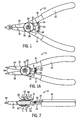
- Figure 1 is a top plan view of a retaining ring pliers having a slidable switching mechanism embodying the present invention and set in an external ring mode, the pliers being shown with its handles at rest and the jaws together;
- Figure 1A is a view like Fig. 1 but set in an internal ring mode showing disposition of the handles with a slight squeezing pressure having been applied thereto;
- Figure 2 is a side elevational view of Fig. 1A ;
- Figure 3 is an exploded view of Fig. 1 ;
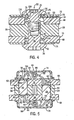
- Figure 4 is a sectional view taken on line 4-4 of Fig. 2 ;
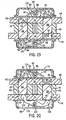
- Figure 5 is a sectional view taken on line 5-5 of Fig. 2 showing the transfer pins in the internal ring mode;
- Figure 6 is a sectional view like Fig. 5 showing the transfer pins in an external ring mode
- Figure 7 is a sectional view similar to Fig. 5 showing the transfer pins in the internal ring mode with the plier's handles at rest;
- Figure 8 is a sectional view like Fig. 7 showing the transfer pins in the external ring mode
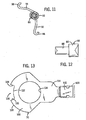
- Figure 9 is a bottom view of a housing assembly forming part of the switching mechanism
- Figure 10 is a sectional view taken on line 10-10 of Fig. 9 ;
- Figure 11 is a perspective view of a rocker or torsion spring used in the housing assembly
- Figure 12 is a top plan view of a spring pin used in the spring housing assembly
- Figure 13 is a top plan view of a switchplate used in the switching mechanism
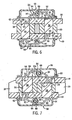
- Figure 14 is a sectional view taken on line 14-14 of Fig. 2 showing an external ring mode
- Figure 15 is a sectional view like Fig. 14 showing an internal ring mode
- Figure 16 is a bottom view showing the position of the switchplate relative to the housing assembly in the internal ring mode.
- Figure 17 is a side elevational view similar to Fig. 2 showing an alternative embodiment which utilizes a switching mechanism provided with two switchplates;
- Figure 18 is a sectional view similar to Fig. 5 showing the embodiment of Fig. 17 ;
- Figure 19 is a sectional view similar to Fig. 6 showing the embodiment of Fig.17 ;
- Fig. 20 is a sectional view like Fig. 5 showing another alternative embodiment which utilizes a solid rocker member in place of a spring in the lower housing.
- the pliers 10 is generally comprised of a pair of handles 14,16 a pair of elongated jaws 18, 20 and a pivot pin 22.
- the pivot pin 22 is preferably formed by a screw 24 having a head 25, a shank 26 and a threaded shaft 27 which is threadably received in a barrel 28 of a nut 30 with a head 31.
- the handles 14, 16 include grips 32 that provide covering to the handles which are generally manufactured of a hard metal.
- the handles 14, 16 are urged apart by a spring 34 disposed between two opposed lugs 36, 38 on the interior sides of both handles 14,16.
- the jaws 18, 20 are designed for mounting of work implements in the form of elongated retaining ring tips 40 having operator posts at the distal ends to be received in the lug holes of standard retaining rings.
- each jaw 18, 20 is disposed in side-by-side relation and have transverse, cylindrically concave bearing recesses 42 for bearing engagement with a cylindrical portion of pivot pin 22.
- each jaw 18, 20 is provided with a projecting semicircular flange 44 which provides an external bearing shoulder 46 concentric with its bearing recess 42.
- the handles 14 and 16 may be fabricated from suitable plate material, such as steel and are engaged at the opposite ends thereof to define end plates 48, 49 which are disposed parallel to each other to partially confine the jaws 18 and 20 and to enclose other components of the pliers 10 to be described.
- the handle end plates 48, 49 are provided with transverse bores 50 to pass the pivot pin 22, and internal cylindrical bearing shoulders 52 for coaction with the bearing shoulders 46 of the jaws 18, 20. Through coaction then of the pivot pin 22 and the bearing shoulders 46 and 52, both jaws 18, 20 and both handles 14,16 are mounted for rotation about a common defined axis. These principal components are maintained in the operative position by the pivot pin 22.
- the heads of the handle plates 48, 49 are formed with vertical channels 53 ( Fig. 3 ) for a purpose to be appreciated hereafter.
- each jaw 18, 20 is operatively linked to one or the other of the handles 14, 16 for oscillation therewith about the pivot 22.
- each jaw 18, 20 is provided at its inner end with a transverse cylindrical bore 54 ( Figs. 3 , 5 ) spaced from and parallel to its respective bearing recess 42.
- Elongated cylindrical transfer pins 56 and 58 are disposed in these bores 54 and are designed for a close sliding fit within the bores, as best seen in Figs. 5 and 6 .
- the handle end plates 48, 49 are each provided with a pair of transverse bores 60 and 62 spaced from each other and from the pivot pin bore 50 and disposed to be axially aligned with respective bores 54 of the jaws 18, 20 in selective relative position.
- These handle bores 60, 62 have the same diameter as the bores 54 of the jaws 18, 20 so that when a transfer pin 56, 58 is received within a handle bore 60, 62, that handle 14,16 is securely coupled to the respective jaw 18,20.
- the transfer pins 56, 58 have a length such that when the pin is fully confined within a jaw bore 54, it has an outermost end 64 or 65 which is flush with the external face of the handle end plate 48 or 49.
- the slidable switching mechanism 12 is comprised of a first or upper reaction member housing assembly 66, a second or lower reaction member housing assembly 68 and a movable switchplate 70.
- the first reaction member housing assembly 66 is disposed above handle plate 48, and the second reaction member housing assembly 68 is positioned upon handle plate 49.
- Switchplate 70 is interposed and movably mounted between first reaction member housing assembly 66 and handle plate 48.
- reaction member housing assemblies 66 and 68 are identical and include a respective cover 72, 73 formed by a planar thin plate having a curved periphery 74 and a central aperture 76.
- Each cover 72, 73 is formed on one side with a switchplate-engaging tab 78 extending at generally 90° relative to the plane of the plate, and is constructed on an opposite side with a kidney-shaped dome 80. Notches 79 are formed in each cover 72, 73 on opposite sides of tab 78 to provide material relief. Tabs 78 are designed to be aligned in the recesses 53 formed in the heads of handle plates 48, 49.
- the dome 80 on each cover 72, 73 defines a retaining pocket for holding a spring pin 82 and reaction member in the form of a rocker or torsion spring 84.
- Each spring pin 82 has a head 86 and a stem 88 of smaller diameter than the head.
- Each torsion spring 84 has a central coiled portion 90 integrally joined to a pair of oppositely directed spring arms 92, 94 having curled free ends 96,98, respectively ( Figs. 5-8 ).
- the coiled portion 90 of each torsion spring 84 is rotatably disposed about the stem 88 of a respective spring pin 82 so that the spring 84 rotates with respect thereto during operation of the switching mechanism 12.
- the shank 26 of screw 24 passes through the central aperture 76 of the first reaction member housing assembly cover 72.
- the barrel 28 of nut 30 passes through the central aperture 76 of the second reaction member housing assembly cover 73.
- Head 25 of screw 24 engages the cover 72 of the first reaction member housing assembly 66, while head 31 of nut 30 engages the cover 73 of the second reaction member housing assembly 68.
- switchplate 70 includes a first flat portion 100 which lies between the first reaction member housing assembly 66 and handle plate 48, and a second flat portion 102 offset from and lying in a horizontal plane above the horizontal plane of the first portion 100.
- Second portion 102 typically carries a protective covering 103 surrounding its surface area.
- the first portion 100 is formed with a central opening 104 and has a periphery 105 provided with a recess 106 defined by side walls 108, 110 and bottom wall 112.
- First portion 100 also includes an engagement surface 114 located between the opening 104 and the second portion 102.
- the diameter of opening 104 is larger than the diameter of aperture 76 in covers 72, 73 so that a washer 116 ( Figs. 3 and 4 ) can be received within the surrounding wall forming opening 104.
- the washer 116 has a hole 118 throughwhich the screw shank 26 passes.
- the thickness of washer 116 is slightly greater than the thickness of switchplate 70 in surrounding relationship therewith.
- the switchplate 70 is slidably mounted for limited rotation about washer 116 between cover 72 and handle plate 48.
- clamping pressure is applied to the threaded screw 24 through the inner portion of the cover 72, and washer 116 onto handle plate 48 in a manner which will hold the pliers 10 together without impeding the movement of the switchplate 70.
- second portion 102 of switchplate 70 extends beyond the periphery of cover 72 and defines an actuator for easily moving the switchplate 70 from side-to-side using a single finger, such as one's thumb, while the pliers is being held.
- the side-to-side travel of the switchplate 70 is limited by the engagement of the tab 78 and cover 72 with either of the switchplate side walls 108, 110.
- each jaw 18 or 20 may be selectively rigidly linked or coupled to a selected handle 14 or 16.
- the described convertible retaining ring pliers 10 is adapted for two operational modes which may be referred to as "the external ring mode" and the “internal ring mode”.
- a legend "EXT” is imprinted on the end plate 48 of the handle 16 adjacent to the bore 62 which is positioned to receive the transfer pin 56, and the legend "INT" is placed on the end plate 48 adjacent to the bore 60 which is positioned to receive the transfer pin 58.
- the switchplate actuator 102 is shifted to cover the INT legend and with the EXT legend visible informs the user that the pliers 10 is in the "external ring mode".
- switchplate actuator 102 covers the EXT legend and provides the visible INT legend "internal ring mode” indication to the user.
- Figs. 1 , 6 , 8 and 14 particularly illustrate the external ring mode.
- the jaw 18 is coupled to the handle 14, and the jaw 20 is coupled to the handle 16 so that squeezing of the handles toward each other will result in corresponding divergence of the tips 40 away from each other.
- Switchplate 70 is slidably positioned by moving actuator 102 so that side wall 110 engages tab 78 on upper reaction member housing assembly 66 ( Fig. 9 ).
- the pliers 10 When it is desired to convert the pliers 10 to the internal ring mode, the pliers 10 are held at rest and the user simply uses one finger, such as a thumb, to slide the switchplate actuator 102 to the left ( Fig. 15 ) so that it covers the EXT legend.
- Switchplate 70 is slidably positioned so that the side wall 108 engages tab 78 of upper reaction member housing assembly 66 as seen in Fig. 16 .
- a clicking can be sensed as the transfer pins 56, 58 change position.
- the jaws 18, 20 will be apart. Squeezing the handles 14,16 will now enable the tips 40 to come together.
- Moving the switchplate 70 from right to left does not actually convert the pliers 10 from external to internal ring mode. Rather, it sets up the mechanism to make the conversion once the respective bores 54, 60 and 62 are aligned. Shifting of the switchplate 70 lifts the curled end 98 of spring arm 94 of spring 84 in the upper reaction member housing assembly 66 out of the bore 62, and releases the curled end 96 of spring arm 92 to put pressure on the transfer pin 58, but the pin 58 cannot move. As the handles 14, 16 are squeezed together ( Fig. 5 ), the bores 54 in the jaws and the bores 60, 62 in the handle plates 48, 49 will all come into alignment at the same moment.
- the user slides the switchplate actuator 102 to the right so that it covers the INT legend. Again, side wall 110 engages tab 78 of upper reaction member housing assembly 66. As the pliers 10 are gently squeezed together, a clicking again is sensed as the transfer pins 56, 58 change position. When the handles 14,16 are released, a further clicking may be heard as the transfer pins 56, 58 finish changing position. Now with the handles 14,16 at rest, the jaws 18,20 will be together in the external ring mode. Squeezing the handles 14, 16 together will move the tips 40 apart. As before, the movement of switchplate 70 from left to right does not actually convert the pliers 10 from internal to external ring mode.
- the switching mechanism 12 performs two functions incidental to the operation of pliers 10.
- One function is that the position of slidable switchplate 70 coacting with the legend provided on the external handle surface provides a visual indication of the operating mode or position of the pliers 10.
- Another function is the convenience of shifting the transfer pins 56, 58 to convert the pliers-to an alternative operational mode. During that shifting, the transfer pins 56, 58 are readily and simultaneously moved into their desired positions without need for an additional implement or applying finger pressure directly to the transfer pins of 56, 58.
- the invention contemplates an alternative embodiment using two identical switching mechanisms 12 and 13 wherein two identical switchplates 70, 71 are used such as illustrated in Figs. 17, 18 and 19 .
- switchplates 70, 71 are manually positioned together in either the external or internal ring mode.
- Fig. 20 Another alternative embodiment is shown in Fig. 20 wherein a solid non-flexing rocker 120 is used in place of spring 84 in lower housing assembly 68 and defines the lower reaction member.
- the rocker 120 pivots about a pin 122 and has rigid free ends 124, 126 which engage bottom ends of transfer pins 56, 58, respectively.
- the rigid free ends 124, 126 move similar to spring ends 96, 98, however, they provide a more precise movement to give better control of the switching mechanism 12. Accordingly, the foregoing description is meant to be exemplary only and should not be deemed limitative on the scope of the invention set forth with the following claims.
Landscapes
- Engineering & Computer Science (AREA)
- Mechanical Engineering (AREA)
- Hand Tools For Fitting Together And Separating, Or Other Hand Tools (AREA)
- Arc-Extinguishing Devices That Are Switches (AREA)
- Gripping Jigs, Holding Jigs, And Positioning Jigs (AREA)
Claims (14)
- Verstellbare Sicherungsringzange, die einen Drehzapfen (26, 28), erste und zweite Klemmbacken (18, 20), die an dem Drehzapfen für eine aufeinander zu und voneinander weg gerichtete Drehbewebung befestigt sind, und erste und zweite Griffe (14, 16) aufweist, die an dem Drehzapfen für eine aufeinander zu und voneinander weg gerichtete Drehbewegung befestigt sind, wobei die Griffe Abschnitte (48, 49) aufweisen, die an den Drehzapfen angrenzen und die jeweils auf einander entgegengesetzten Seiten der Klemmbacken angeordnet sind, wobei jede Klemmbacke eine Querbohrung (54) aufweist, die parallel zur Drehzapfenachse ist, und in der jeweils ein entsprechender Übertragungsstift (56, 58) drehbar aufgenommen ist, wobei jeder der Griffabschnitte zwei voneinander beabstandete Löcher (60, 62) aufweist, die so angeordnet sind, dass sie die Übertragungsstifte aufnehmen können, wobei die Übertragungsstifte (56, 58) verschieblich in ausgewählten Löchern (60, 62) der ersten und zweiten Griffe in Eingriff eingesetzt sind, um erste und zweite Betätigungsstellungen zu definieren, so dass, wenn die Griffe (14, 16) in der ersten Betätigungsstellung aufeinander zu bewegt werden, die Bewegung der Klemmbacken (18, 20) aufeinander zu erfolgt, und die Bewegung der Klemmbacken in der zweiten Betätigungsstellung voneinander weg erfolgt,
dadurch gekennzeichnet, dass:ein Schaltmechanismus (12) so am Drehzapfen (26, 28) befestigt ist, dass er die Außenflächen der Griffabschnitte (48, 49) und der Übertragungsstifte (56, 58) berührt, um eine gleichzeitige Verschiebung der Übertragungsstifte in die Löcher und aus den Löchern (60, 62) der ersten und zweiten Griffabschnitte zu ermöglichen, wobei der Schaltmechanismus (12) eine erste Drehmomentstützen-Gehäusebaugruppe (66), die der Außenfläche eines Griffabschnitts (48) zugeordnet ist und eine erste Drehmomentstütze (84) aufweist, eine zweite Drehmomentstützen-Gehäusebaugruppe (68), die der Außenfläche des anderen Griffabschnitts (49) zugeordnet ist und eine zweite Drehmomentstütze (84) aufweist, und eine Schaltplattenstruktur (70), die drehbar um den Drehzapfen angebracht und zwischen mindestens einer Drehmomentstützen-Gehäusebaugruppe (66) und der Außenfläche des damit verbundenen Griffabschnitts (48) angeordnet ist, aufweist, wobei die Schaltplattenstruktur (70) so verdreht werden kann, dass sie mit einem ausgewählten Teil (96, 98) der Drehmomentstütze (84) innerhalb der mindestens einen Drehmomentstützen-Gehäusebaugruppe (66) und mit einem Ende (64, 65) eines Übertragungsstifts (56, 58) in Eingriff kommt. - Verstellbare Sicherungsringzange nach Anspruch 1, wobei jede der Drehmomentstützen-Gehäusebaugruppen (66, 68) eine Abdeckung (72, 73) aufweist, die mit einem gewölbten Abschnitt (80) versehen ist, um die jeweilige Drehmomentstütze (84) festzuhalten, und wobei jede Drehmomentstütze einen mittleren Abschnitt (90) aufweist, der sich drehend um einen Stift bewegt.
- Verstellbare Sicherungsringzange nach Anspruch 2, wobei jede Drehmomentstütze (84) eine Feder mit einem spiralförmigen mittleren Abstand (90) ist.
- Verstellbare Sicherungsringzange nach Anspruch 3, wobei die Feder ferner zwei sich in entgegengesetzte Richtungen erstreckende Federarme (92, 94) aufweist, die an den spiralförmigen mittleren Abschnitt (90) angefügt sind.
- Verstellbare Sicherungsringzange nach Anspruch 4, wobei jeder Federarm (92, 94) in einem gebogenen Ende (96, 98) endet.
- Verstellbare Sicherungsringzange nach Anspruch 5, wobei jedes gebogene Ende (96, 98) der Feder in der zweiten Drehmomentstützen-Gehäusebaugruppe (68) mit einem entsprechenden Übertragungsstift (55, 58) in Eingriff steht.
- Verstellbare Sicherungsringzange nach Anspruch 5 oder 6, wobei ein gebogenes Ende (96 oder 98) der Feder in der ersten Drehmomentstützen-Gehäusebaugruppe (66) mit der Schaltplattenstruktur (70) in Eingriff steht und das andere Ende (96 oder 98) der Feder in der ersten Drehmomentstützen-Gehäusebaugruppe mit einem Übertragungsstift (56 oder 58) in Eingriff steht.
- Verstellbare Sicherungsringzange nach einem der Ansprüche 2 bis 7, wobei jede Abdeckung (72, 73) eine dünne Platte mit einer mittleren Öffnung (76) zur Aufnahme des Drehzapfens (26, 28) und eine Lasche (78) aufweist, die im Wesentlichen senkrecht von der dünnen Platte ausgeht, um in eine entsprechende Vertiefung (53) im zugehörigen Griffabschnitt (48, 49) einzugreifen.
- Verstellbare Sicherungsringzange nach Anspruch 8, wobei in jedem Griffabschnitt (48, 49) ein vertikaler Kanal (53) ausgebildet ist, in dem die Lasche (78) der zugehörigen Abdeckung aufgenommen wird.
- Verstellbare Sicherungsringzange nach einem der Ansprüche 2 bis 9, wobei die Schaltplattenstruktur (70) einen ersten flachen Abschnitt (100), der zwischen der Abdeckung (72) und der Außenfläche des einen Griffabschnitts (48) liegt, und einen zweiten flachen Abschnitt (102) aufweist, der vom ersten flachen Abschnitt ausgeht und der ein Stellglied definiert, das dafür ausgelegt ist, von einem Benutzer mit einem einzigen Finger betätigt zu werden, wenn die Schaltplattenstruktur bewegt werden soll.
- Verstellbare Sicherungsringzange nach Anspruch 8 oder Anspruch 9, wobei in der Schaltplattenstruktur (70) eine Vertiefung (106) ausgebildet ist, die zwei voneinander beabstandete Seitenwände (108, 110) aufweist, die jeweils mit der Lasche (78) auf der Abdeckung in Eingriff gebracht werden können, wenn die Schaltplattenstruktur von einer Seite auf die andere bewegt wird.
- Verstellbare Sicherungsringzange nach einem der vorangehenden Ansprüche, wobei die Schaltplattenstruktur (70) eine Schaltplatte aufweist, die zwischen der ersten Drehmomentstützen-Gehäusebaugruppe (66) und der Außenfläche eines Griffabschnitts (48) angeordnet ist.
- Verstellbare Sicherungsringzange nach Anspruch 12, wobei die Schaltplattenstruktur eine zweite Schaltplatte (71) aufweist, die zwischen der zweiten Drehmomentstützen-Gehäusestruktur (68) und der Außenfläche des anderen Griffabschnitts (49) angeordnet ist.
- Verstellbare Sicherungsringzange nach Anspruch 1 oder Anspruch 2, wobei eine der Drehmomentstützen-Gehäusebaugruppen (66) eine Feder (84) aufweist, die drehbar um einen ersten Stift (88) angebracht ist, und die andere der Drehmomentstützen-Gehäusebaugruppen (68) einen massiven, unflexiblen Schwinghebel (120) aufweist, der verdrehbar um einen zweiten Stift (122) angebracht ist.
Applications Claiming Priority (2)
| Application Number | Priority Date | Filing Date | Title |
|---|---|---|---|
| US11/156,929 US7194936B2 (en) | 2005-06-20 | 2005-06-20 | Slidable switching mechanism for convertible retaining ring pliers |
| PCT/US2006/012350 WO2007001577A1 (en) | 2005-06-20 | 2006-04-03 | Slidable switching mechanism for convertible retaining ring pliers |
Publications (2)
| Publication Number | Publication Date |
|---|---|
| EP1899113A1 EP1899113A1 (de) | 2008-03-19 |
| EP1899113B1 true EP1899113B1 (de) | 2011-05-18 |
Family
ID=36616959
Family Applications (1)
| Application Number | Title | Priority Date | Filing Date |
|---|---|---|---|
| EP06740415A Expired - Lifetime EP1899113B1 (de) | 2005-06-20 | 2006-04-03 | Umwandelbare zange für sicherungsringe |
Country Status (7)
| Country | Link |
|---|---|
| US (1) | US7194936B2 (de) |
| EP (1) | EP1899113B1 (de) |
| JP (1) | JP4950191B2 (de) |
| AT (1) | ATE509737T1 (de) |
| AU (1) | AU2006262861B2 (de) |
| CA (1) | CA2613033C (de) |
| WO (1) | WO2007001577A1 (de) |
Families Citing this family (21)
| Publication number | Priority date | Publication date | Assignee | Title |
|---|---|---|---|---|
| JP4223453B2 (ja) * | 2004-09-21 | 2009-02-12 | 本田技研工業株式会社 | C形クリップの装着治具 |
| USD789169S1 (en) * | 2016-03-16 | 2017-06-13 | Temper Axle Products Corporation | Retaining ring pliers |
| US9764453B1 (en) | 2016-03-16 | 2017-09-19 | Temper Axle Products Corporation | Systems and methods for preloading a bearing |
| US8960057B2 (en) * | 2013-01-21 | 2015-02-24 | Min-Zheng Zeng | C-type pliers |
| USD738174S1 (en) * | 2014-04-24 | 2015-09-08 | A & E Incorporated | Locking pliers |
| USD742194S1 (en) * | 2014-04-24 | 2015-11-03 | A & E Incorporated | Locking pliers |
| CN104476430A (zh) * | 2014-12-19 | 2015-04-01 | 南京化工职业技术学院 | 一种卡圈拆卸钳 |
| TWI564120B (zh) * | 2016-01-08 | 2017-01-01 | Auto Skill Industrial Co Ltd | Disassembly Clamp of Dust Cover for Motor Drive Shaft |
| US9850943B1 (en) | 2017-04-07 | 2017-12-26 | Temper Axle Products Corporation | Systems and methods for preloading a bearing and aligning a lock nut |
| US10107331B1 (en) | 2017-04-07 | 2018-10-23 | Temper Axle Products Corporation | Systems and methods for preloading a bearing and aligning a lock nut |
| US10974544B2 (en) | 2017-04-07 | 2021-04-13 | Temper Axle Products Corporation | Systems and methods for preloading a bearing and aligning a lock nut |
| US10100872B1 (en) | 2017-04-07 | 2018-10-16 | Templer Axle Products Corporation | Systems and methods for preloading a bearing and aligning a lock nut |
| US10107324B1 (en) | 2017-08-08 | 2018-10-23 | Temper Axle Products Corporation | Lock nut with offset retaining ring |
| US10982706B2 (en) | 2017-08-08 | 2021-04-20 | Temper Axle Products Corporation | Lock nut with adjustable retaining ring |
| US20190118347A1 (en) * | 2017-10-23 | 2019-04-25 | Min-Zheng Zeng | Replacement structre of pair of pliers |
| US10968945B2 (en) | 2018-07-02 | 2021-04-06 | Temper Axle Products Corporation | Lock nut with rotatably alignable retaining ring |
| US11986934B2 (en) | 2021-11-01 | 2024-05-21 | Snap-On Incorporated | Adjustable pliers |
| CN222570740U (zh) | 2021-11-24 | 2025-03-07 | 米沃奇电动工具公司 | 钳子存放架以及用于存放手柄朝向打开位置偏置的钳子的存放架 |
| US12214476B2 (en) | 2022-03-10 | 2025-02-04 | A & E Incorporated | Switchable pliers and method for use |
| DE102022204845B3 (de) | 2022-05-17 | 2023-11-02 | Zf Friedrichshafen Ag | Zangenwerkzeug |
| TWI886058B (zh) * | 2024-10-01 | 2025-06-01 | 桔林工業股份有限公司 | C型扣環鉗 |
Family Cites Families (8)
| Publication number | Priority date | Publication date | Assignee | Title |
|---|---|---|---|---|
| US4280265A (en) * | 1979-09-10 | 1981-07-28 | Murphy James W | Pliers |
| US4476750A (en) | 1983-06-07 | 1984-10-16 | Murphy James W | Latching mechanism |
| US4625379A (en) * | 1984-11-08 | 1986-12-02 | Milbar Corporation | Retaining ring tool |
| JP2609072B2 (ja) * | 1994-10-14 | 1997-05-14 | 磐田電工株式会社 | 軸用および孔用止め輪の脱着具 |
| US6378403B1 (en) * | 1999-12-17 | 2002-04-30 | Stride Tool, Inc. | Universal retaining ring plier |
| WO2001076826A1 (en) * | 2000-04-05 | 2001-10-18 | Stride Tool, Inc. | Universal retaining ring plier tool |
| TW454653U (en) * | 2000-11-03 | 2001-09-11 | Jang Shiue Chin | Spring clip for both inner and outer C-typed clips |
| US6983677B1 (en) * | 2004-04-05 | 2006-01-10 | A&E Incorporated | Switching mechanism for convertible retaining ring pliers |
-
2005
- 2005-06-20 US US11/156,929 patent/US7194936B2/en not_active Expired - Lifetime
-
2006
- 2006-04-03 EP EP06740415A patent/EP1899113B1/de not_active Expired - Lifetime
- 2006-04-03 AT AT06740415T patent/ATE509737T1/de not_active IP Right Cessation
- 2006-04-03 WO PCT/US2006/012350 patent/WO2007001577A1/en not_active Ceased
- 2006-04-03 JP JP2008518136A patent/JP4950191B2/ja not_active Expired - Lifetime
- 2006-04-03 CA CA2613033A patent/CA2613033C/en not_active Expired - Lifetime
- 2006-04-03 AU AU2006262861A patent/AU2006262861B2/en not_active Ceased
Also Published As
| Publication number | Publication date |
|---|---|
| AU2006262861B2 (en) | 2010-12-23 |
| US7194936B2 (en) | 2007-03-27 |
| WO2007001577A1 (en) | 2007-01-04 |
| JP4950191B2 (ja) | 2012-06-13 |
| CA2613033A1 (en) | 2007-01-04 |
| JP2009527364A (ja) | 2009-07-30 |
| EP1899113A1 (de) | 2008-03-19 |
| CA2613033C (en) | 2011-12-20 |
| AU2006262861A1 (en) | 2007-01-04 |
| ATE509737T1 (de) | 2011-06-15 |
| US20060283291A1 (en) | 2006-12-21 |
Similar Documents
| Publication | Publication Date | Title |
|---|---|---|
| EP1899113B1 (de) | Umwandelbare zange für sicherungsringe | |
| US6983677B1 (en) | Switching mechanism for convertible retaining ring pliers | |
| US7571517B2 (en) | Multi-function tool handle | |
| US6378403B1 (en) | Universal retaining ring plier | |
| US7735399B2 (en) | Clamping and cutting apparatus with adjustable head | |
| US2667678A (en) | Hand clamp | |
| US6128805A (en) | Multipurpose folding tool handle | |
| CN107443314B (zh) | 多用工具 | |
| US6786117B1 (en) | Versatile use pliers | |
| US6792837B2 (en) | Universal retaining ring plier tool | |
| US20030164073A1 (en) | Tool | |
| US9003931B2 (en) | Replaceable jaw members for pliers | |
| US20250178170A1 (en) | Switchable pliers and method for use | |
| TWI787062B (zh) | 具有撥轉定位裝置之可調式扳手 | |
| MX2007015964A (en) | Slidable switching mechanism for convertible retaining ring pliers | |
| US6789452B1 (en) | Increased torque applying pliers | |
| US20180250796A1 (en) | Ratchet wrench | |
| CA1202803A (en) | Circlip pliers | |
| JPH0197573A (ja) | 手工具 | |
| EP1270149B1 (de) | Umkehrbarer Ratschenschlüssel für hohe Drehmomente | |
| WO2018141137A1 (en) | Ratchet wrench | |
| EP3403767A1 (de) | Handgriffklemme | |
| HK40024428A (en) | Multipurpose tool having accessible tool members | |
| HK40024428B (en) | Multipurpose tool having accessible tool members | |
| HK1240890B (en) | Multipurpose tool |
Legal Events
| Date | Code | Title | Description |
|---|---|---|---|
| PUAI | Public reference made under article 153(3) epc to a published international application that has entered the european phase |
Free format text: ORIGINAL CODE: 0009012 |
|
| 17P | Request for examination filed |
Effective date: 20071220 |
|
| AK | Designated contracting states |
Kind code of ref document: A1 Designated state(s): AT BE BG CH CY CZ DE DK EE ES FI FR GB GR HU IE IS IT LI LT LU LV MC NL PL PT RO SE SI SK TR |
|
| RAP1 | Party data changed (applicant data changed or rights of an application transferred) |
Owner name: A & E INCORPORATED |
|
| RIN1 | Information on inventor provided before grant (corrected) |
Inventor name: ENGEL, BRUCE J. Inventor name: MURPHY, JAMES Inventor name: GERBERT, LARRY |
|
| 17Q | First examination report despatched |
Effective date: 20080414 |
|
| DAX | Request for extension of the european patent (deleted) | ||
| GRAP | Despatch of communication of intention to grant a patent |
Free format text: ORIGINAL CODE: EPIDOSNIGR1 |
|
| RTI1 | Title (correction) |
Free format text: CONVERTIBLE RETAINING RING PLIERS |
|
| GRAS | Grant fee paid |
Free format text: ORIGINAL CODE: EPIDOSNIGR3 |
|
| GRAA | (expected) grant |
Free format text: ORIGINAL CODE: 0009210 |
|
| AK | Designated contracting states |
Kind code of ref document: B1 Designated state(s): AT BE BG CH CY CZ DE DK EE ES FI FR GB GR HU IE IS IT LI LT LU LV MC NL PL PT RO SE SI SK TR |
|
| REG | Reference to a national code |
Ref country code: GB Ref legal event code: FG4D |
|
| REG | Reference to a national code |
Ref country code: CH Ref legal event code: EP |
|
| REG | Reference to a national code |
Ref country code: IE Ref legal event code: FG4D |
|
| REG | Reference to a national code |
Ref country code: DE Ref legal event code: R096 Ref document number: 602006022063 Country of ref document: DE Effective date: 20110630 |
|
| REG | Reference to a national code |
Ref country code: NL Ref legal event code: VDEP Effective date: 20110518 |
|
| PG25 | Lapsed in a contracting state [announced via postgrant information from national office to epo] |
Ref country code: LT Free format text: LAPSE BECAUSE OF FAILURE TO SUBMIT A TRANSLATION OF THE DESCRIPTION OR TO PAY THE FEE WITHIN THE PRESCRIBED TIME-LIMIT Effective date: 20110518 Ref country code: PT Free format text: LAPSE BECAUSE OF FAILURE TO SUBMIT A TRANSLATION OF THE DESCRIPTION OR TO PAY THE FEE WITHIN THE PRESCRIBED TIME-LIMIT Effective date: 20110919 Ref country code: SE Free format text: LAPSE BECAUSE OF FAILURE TO SUBMIT A TRANSLATION OF THE DESCRIPTION OR TO PAY THE FEE WITHIN THE PRESCRIBED TIME-LIMIT Effective date: 20110518 |
|
| PG25 | Lapsed in a contracting state [announced via postgrant information from national office to epo] |
Ref country code: GR Free format text: LAPSE BECAUSE OF FAILURE TO SUBMIT A TRANSLATION OF THE DESCRIPTION OR TO PAY THE FEE WITHIN THE PRESCRIBED TIME-LIMIT Effective date: 20110819 Ref country code: ES Free format text: LAPSE BECAUSE OF FAILURE TO SUBMIT A TRANSLATION OF THE DESCRIPTION OR TO PAY THE FEE WITHIN THE PRESCRIBED TIME-LIMIT Effective date: 20110829 Ref country code: FI Free format text: LAPSE BECAUSE OF FAILURE TO SUBMIT A TRANSLATION OF THE DESCRIPTION OR TO PAY THE FEE WITHIN THE PRESCRIBED TIME-LIMIT Effective date: 20110518 Ref country code: CY Free format text: LAPSE BECAUSE OF FAILURE TO SUBMIT A TRANSLATION OF THE DESCRIPTION OR TO PAY THE FEE WITHIN THE PRESCRIBED TIME-LIMIT Effective date: 20110518 Ref country code: BE Free format text: LAPSE BECAUSE OF FAILURE TO SUBMIT A TRANSLATION OF THE DESCRIPTION OR TO PAY THE FEE WITHIN THE PRESCRIBED TIME-LIMIT Effective date: 20110518 Ref country code: SI Free format text: LAPSE BECAUSE OF FAILURE TO SUBMIT A TRANSLATION OF THE DESCRIPTION OR TO PAY THE FEE WITHIN THE PRESCRIBED TIME-LIMIT Effective date: 20110518 Ref country code: AT Free format text: LAPSE BECAUSE OF FAILURE TO SUBMIT A TRANSLATION OF THE DESCRIPTION OR TO PAY THE FEE WITHIN THE PRESCRIBED TIME-LIMIT Effective date: 20110518 Ref country code: IS Free format text: LAPSE BECAUSE OF FAILURE TO SUBMIT A TRANSLATION OF THE DESCRIPTION OR TO PAY THE FEE WITHIN THE PRESCRIBED TIME-LIMIT Effective date: 20110918 Ref country code: LV Free format text: LAPSE BECAUSE OF FAILURE TO SUBMIT A TRANSLATION OF THE DESCRIPTION OR TO PAY THE FEE WITHIN THE PRESCRIBED TIME-LIMIT Effective date: 20110518 |
|
| PG25 | Lapsed in a contracting state [announced via postgrant information from national office to epo] |
Ref country code: NL Free format text: LAPSE BECAUSE OF FAILURE TO SUBMIT A TRANSLATION OF THE DESCRIPTION OR TO PAY THE FEE WITHIN THE PRESCRIBED TIME-LIMIT Effective date: 20110518 |
|
| PG25 | Lapsed in a contracting state [announced via postgrant information from national office to epo] |
Ref country code: CZ Free format text: LAPSE BECAUSE OF FAILURE TO SUBMIT A TRANSLATION OF THE DESCRIPTION OR TO PAY THE FEE WITHIN THE PRESCRIBED TIME-LIMIT Effective date: 20110518 Ref country code: EE Free format text: LAPSE BECAUSE OF FAILURE TO SUBMIT A TRANSLATION OF THE DESCRIPTION OR TO PAY THE FEE WITHIN THE PRESCRIBED TIME-LIMIT Effective date: 20110518 |
|
| PG25 | Lapsed in a contracting state [announced via postgrant information from national office to epo] |
Ref country code: DK Free format text: LAPSE BECAUSE OF FAILURE TO SUBMIT A TRANSLATION OF THE DESCRIPTION OR TO PAY THE FEE WITHIN THE PRESCRIBED TIME-LIMIT Effective date: 20110518 Ref country code: RO Free format text: LAPSE BECAUSE OF FAILURE TO SUBMIT A TRANSLATION OF THE DESCRIPTION OR TO PAY THE FEE WITHIN THE PRESCRIBED TIME-LIMIT Effective date: 20110518 Ref country code: SK Free format text: LAPSE BECAUSE OF FAILURE TO SUBMIT A TRANSLATION OF THE DESCRIPTION OR TO PAY THE FEE WITHIN THE PRESCRIBED TIME-LIMIT Effective date: 20110518 Ref country code: PL Free format text: LAPSE BECAUSE OF FAILURE TO SUBMIT A TRANSLATION OF THE DESCRIPTION OR TO PAY THE FEE WITHIN THE PRESCRIBED TIME-LIMIT Effective date: 20110518 |
|
| PLBE | No opposition filed within time limit |
Free format text: ORIGINAL CODE: 0009261 |
|
| STAA | Information on the status of an ep patent application or granted ep patent |
Free format text: STATUS: NO OPPOSITION FILED WITHIN TIME LIMIT |
|
| 26N | No opposition filed |
Effective date: 20120221 |
|
| PG25 | Lapsed in a contracting state [announced via postgrant information from national office to epo] |
Ref country code: IT Free format text: LAPSE BECAUSE OF FAILURE TO SUBMIT A TRANSLATION OF THE DESCRIPTION OR TO PAY THE FEE WITHIN THE PRESCRIBED TIME-LIMIT Effective date: 20110518 |
|
| REG | Reference to a national code |
Ref country code: DE Ref legal event code: R097 Ref document number: 602006022063 Country of ref document: DE Effective date: 20120221 |
|
| PG25 | Lapsed in a contracting state [announced via postgrant information from national office to epo] |
Ref country code: MC Free format text: LAPSE BECAUSE OF NON-PAYMENT OF DUE FEES Effective date: 20120430 |
|
| REG | Reference to a national code |
Ref country code: CH Ref legal event code: PL |
|
| REG | Reference to a national code |
Ref country code: IE Ref legal event code: MM4A |
|
| PG25 | Lapsed in a contracting state [announced via postgrant information from national office to epo] |
Ref country code: LI Free format text: LAPSE BECAUSE OF NON-PAYMENT OF DUE FEES Effective date: 20120430 Ref country code: CH Free format text: LAPSE BECAUSE OF NON-PAYMENT OF DUE FEES Effective date: 20120430 Ref country code: IE Free format text: LAPSE BECAUSE OF NON-PAYMENT OF DUE FEES Effective date: 20120403 |
|
| PG25 | Lapsed in a contracting state [announced via postgrant information from national office to epo] |
Ref country code: BG Free format text: LAPSE BECAUSE OF FAILURE TO SUBMIT A TRANSLATION OF THE DESCRIPTION OR TO PAY THE FEE WITHIN THE PRESCRIBED TIME-LIMIT Effective date: 20110818 |
|
| PG25 | Lapsed in a contracting state [announced via postgrant information from national office to epo] |
Ref country code: TR Free format text: LAPSE BECAUSE OF FAILURE TO SUBMIT A TRANSLATION OF THE DESCRIPTION OR TO PAY THE FEE WITHIN THE PRESCRIBED TIME-LIMIT Effective date: 20110518 |
|
| PG25 | Lapsed in a contracting state [announced via postgrant information from national office to epo] |
Ref country code: LU Free format text: LAPSE BECAUSE OF NON-PAYMENT OF DUE FEES Effective date: 20120403 |
|
| PG25 | Lapsed in a contracting state [announced via postgrant information from national office to epo] |
Ref country code: HU Free format text: LAPSE BECAUSE OF FAILURE TO SUBMIT A TRANSLATION OF THE DESCRIPTION OR TO PAY THE FEE WITHIN THE PRESCRIBED TIME-LIMIT Effective date: 20060403 |
|
| REG | Reference to a national code |
Ref country code: FR Ref legal event code: PLFP Year of fee payment: 11 |
|
| REG | Reference to a national code |
Ref country code: FR Ref legal event code: PLFP Year of fee payment: 12 |
|
| REG | Reference to a national code |
Ref country code: FR Ref legal event code: PLFP Year of fee payment: 13 |
|
| PGFP | Annual fee paid to national office [announced via postgrant information from national office to epo] |
Ref country code: DE Payment date: 20210420 Year of fee payment: 16 |
|
| REG | Reference to a national code |
Ref country code: DE Ref legal event code: R119 Ref document number: 602006022063 Country of ref document: DE |
|
| PG25 | Lapsed in a contracting state [announced via postgrant information from national office to epo] |
Ref country code: DE Free format text: LAPSE BECAUSE OF NON-PAYMENT OF DUE FEES Effective date: 20221103 |
|
| PGFP | Annual fee paid to national office [announced via postgrant information from national office to epo] |
Ref country code: FR Payment date: 20230420 Year of fee payment: 18 |
|
| P01 | Opt-out of the competence of the unified patent court (upc) registered |
Effective date: 20230718 |
|
| PG25 | Lapsed in a contracting state [announced via postgrant information from national office to epo] |
Ref country code: FR Free format text: LAPSE BECAUSE OF NON-PAYMENT OF DUE FEES Effective date: 20240430 |
|
| PG25 | Lapsed in a contracting state [announced via postgrant information from national office to epo] |
Ref country code: FR Free format text: LAPSE BECAUSE OF NON-PAYMENT OF DUE FEES Effective date: 20240430 |
|
| PGFP | Annual fee paid to national office [announced via postgrant information from national office to epo] |
Ref country code: GB Payment date: 20250418 Year of fee payment: 20 |