EP1898779B1 - Sonde zur messung des sauerstoffgehaltes in biologischem gewebe sowie katheter mit einer derartigen sonde - Google Patents
Sonde zur messung des sauerstoffgehaltes in biologischem gewebe sowie katheter mit einer derartigen sonde Download PDFInfo
- Publication number
- EP1898779B1 EP1898779B1 EP06828784A EP06828784A EP1898779B1 EP 1898779 B1 EP1898779 B1 EP 1898779B1 EP 06828784 A EP06828784 A EP 06828784A EP 06828784 A EP06828784 A EP 06828784A EP 1898779 B1 EP1898779 B1 EP 1898779B1
- Authority
- EP
- European Patent Office
- Prior art keywords
- membrane
- probe
- catheter
- dye
- oxygen
- Prior art date
- Legal status (The legal status is an assumption and is not a legal conclusion. Google has not performed a legal analysis and makes no representation as to the accuracy of the status listed.)
- Expired - Lifetime
Links
Images


Classifications
-
- G—PHYSICS
- G01—MEASURING; TESTING
- G01N—INVESTIGATING OR ANALYSING MATERIALS BY DETERMINING THEIR CHEMICAL OR PHYSICAL PROPERTIES
- G01N21/00—Investigating or analysing materials by the use of optical means, i.e. using sub-millimetre waves, infrared, visible or ultraviolet light
- G01N21/62—Systems in which the material investigated is excited whereby it emits light or causes a change in wavelength of the incident light
- G01N21/63—Systems in which the material investigated is excited whereby it emits light or causes a change in wavelength of the incident light optically excited
- G01N21/64—Fluorescence; Phosphorescence
-
- A—HUMAN NECESSITIES
- A61—MEDICAL OR VETERINARY SCIENCE; HYGIENE
- A61B—DIAGNOSIS; SURGERY; IDENTIFICATION
- A61B5/00—Measuring for diagnostic purposes; Identification of persons
- A61B5/145—Measuring characteristics of blood in vivo, e.g. gas concentration or pH-value ; Measuring characteristics of body fluids or tissues, e.g. interstitial fluid or cerebral tissue
- A61B5/14542—Measuring characteristics of blood in vivo, e.g. gas concentration or pH-value ; Measuring characteristics of body fluids or tissues, e.g. interstitial fluid or cerebral tissue for measuring blood gases
-
- A—HUMAN NECESSITIES
- A61—MEDICAL OR VETERINARY SCIENCE; HYGIENE
- A61B—DIAGNOSIS; SURGERY; IDENTIFICATION
- A61B5/00—Measuring for diagnostic purposes; Identification of persons
- A61B5/145—Measuring characteristics of blood in vivo, e.g. gas concentration or pH-value ; Measuring characteristics of body fluids or tissues, e.g. interstitial fluid or cerebral tissue
- A61B5/1455—Measuring characteristics of blood in vivo, e.g. gas concentration or pH-value ; Measuring characteristics of body fluids or tissues, e.g. interstitial fluid or cerebral tissue using optical sensors, e.g. spectral photometrical oximeters
- A61B5/1459—Measuring characteristics of blood in vivo, e.g. gas concentration or pH-value ; Measuring characteristics of body fluids or tissues, e.g. interstitial fluid or cerebral tissue using optical sensors, e.g. spectral photometrical oximeters invasive, e.g. introduced into the body by a catheter
Definitions
- the invention relates to a probe for measuring the oxygen content in biological material according to the preamble of claim 1 and according to the preamble of claim 9. Furthermore, the invention relates to a catheter with such a probe.
- the measurement of oxygen is of great interest, especially in the field of medicine.
- the in vivo detection of the dissolved, not bound to hemoglobin oxygen for the assessment of the supply of biological material, in particular the tissue, of importance.
- Other examples of biological material to be assayed for oxygen content are body fluids such as blood or cerebrospinal fluid.
- a decisive factor is the oxygen partial pressure prevailing in the examined tissue.
- the partial pressure of the oxygen dissolved physically in the interstitial fluid corresponds to the availability of oxygen at the cellular level.
- the detection of tissue oxygen is used.
- catheters are used for the measurement, which include sensor systems or probes reacting specifically to oxygen.
- a probe of the type mentioned is known from the WO 93/05702 A1 .
- Other probes that measure fiber-optic oxygen parameters of tissue are known from the US 5,673,694 , of the US 5,995,208 , of the US 5,579,774 and the publications cited therein.
- Another fiber optic oxygen probe is known JI Peterson et al., Anal. Chem. 1984, 56, 62-67 .
- Other fiber optic probes are known from the US 4,752,115 A . US 5,142,155 A and US 4,861,727 A ,
- a well-known measuring technique for the fiber-optic measurement of the partial pressure of the physically dissolved, ie free oxygen, is the dynamic oxygen quenching.
- a fluorescent dye embedded in a matrix for example a platinum complex
- the fluorescent dye is optically excited via the fiber, usually by laser radiation, which is tuned to absorption bands of the dye.
- the dye molecules so excited go with time delay, e.g. in the range between 1 and 60 ⁇ s, emitting light of the same or redshifted wavelength into the ground state. In the presence of oxygen, this transition through collision processes can also be radiationless into the ground state.
- the intensity of the light reflected back by the fiber decreases. This reduction is proportional to the free oxygen in the immediate vicinity of the fluorescent dye.
- the known fiber-optic sensors are extremely sensitive to scattered light and intensity-influencing factors such as hairline cracks or fiber curvature. This sensitivity can be reduced if, with the aid of a lock-in technique, the phase shift of the light reflected back from the fluorescent dye relative to the incident light is measured. This exploits the fact that long-lived fluorescence states are statistically more susceptible to the radiationless collision processes of dynamic oxygen quenching.
- a sensitivity of known fiber-optic sensors to scattered light and intensity-influencing factors is also present when measuring with lock-in technology.
- the provision of a gas space surrounding the distal fiber section advantageously increases the measuring volume around the dye by means of an oxygen-permeable and at the same time liquid-impermeable membrane.
- the measurement volume is no longer reduced to the immediate material or tissue environment around the dye, but extended to the outer environment of the gas space predetermining membrane.
- the partial pressure of oxygen forming in the gas space is thus a measure of the mean of the free oxygen content on the outer surface of the membrane which predetermines the gas space.
- the increase in the sensitive volume thus leads to a medically well-usable statement about the local, but not selective oxygen supply in the biological tissue surrounding the probe.
- the tissue condition can be better assessed than in the purely punctual measurement, which is given in the fiber optic measurement methods of the prior art.
- the membrane protects the distal fiber section in the gas space, so that there the risk of disturbing the measurement is prevented.
- the robustness of the fiber-optic sensor according to the invention is still through the use of the aforementioned lock-in technique further increased.
- the oxygen-sensitive dye may be, for example, a platinum complex or a ruthenium complex.
- the oxygen-sensitive dye is present as a coating or is at least partially incorporated into the membrane wall.
- the arrangement of the dye must be such that the most direct possible optical path exists between the dye molecules and the distal end face of the fiber.
- the dye is provided as a direct coating on the distal end surface of the fiber.
- the arrangement of the dye according to the invention as a coating or membrane wall component has the advantage that a light response of the dye is not undesirably absorbed by other dye molecules contained in the volume and thus lost.
- a uniform membrane thickness according to claim 2 prevents a temporal smearing of the partial pressure measurement signal, since the free oxygen molecules have a uniform diffusion time through the membrane. This results in a homogeneous sensor characteristic.
- a uniform membrane thickness does not mean that the membrane thickness over the entire surface of the membrane is exactly constant. Minor deviations from a mean membrane thickness, which do not affect the mentioned homogeneous sensor characteristic in practice, can be tolerated. Such tolerable deviations move, for example, in the range of 200 microns.
- An oxygen-sensitive dye with a long fluorescence lifetime can compensate for spurious effects resulting from membrane strength variations. Therefore, for a homogeneous sensor characteristic For example, a platinum complex with a fluorescence lifetime up to 60 ⁇ s of advantage.
- a gas space according to claim 3 can be realized with a cost-producible membrane. If the gas space longitudinal axis is parallel to and spaced from the fiber axis, the gas space can be designed with a large contiguous free volume, which is suitable for the arrangement of further components, in particular of sensors, the probe. If the axes coincide, results in a rotationally symmetrical structure, which offers particular manufacturing advantages. In the case of coincident axes, an embodiment is particularly suitable in which the distal end face of the fiber with the dye is centered in the gas space, so that a diffusion length symmetry exists with respect to free oxygen which diffuses through the membrane, which can increase the measurement quality.
- a membrane according to claim 4 can be easily prepared, since the membrane tube z. B. can be formed by cutting an endless tube.
- Materials according to claim 5 have been found to be well suited for use in the probe in terms of oxygen permeability and liquid impermeability.
- a membrane according to claim 6 adapts well to the surrounding tissue, so that a falsification of the measurement is prevented.
- An air filling according to claim 7 prevents the gas composition from changing when the probe is stored prior to its use.
- a gas or a gas mixture before use of the probe, which consists of such large molecules that they can not penetrate the oxygen-permeable membrane to the outside.
- a gas space filling for storage of the probe is achieved before their use, which does not change.
- a water vapor permeability according to claim 8 allows due to the increased heat capacity of the gas in the gas space by water vapor, which can penetrate there, a faster adjustment of the sensors located in the gas space to the ambient temperature. As a result, a reliable temperature measurement is possible within the gas space without having to wait long for the settling of a thermal equilibrium. Therefore, if emphasis is placed on a high water vapor permeability, the membrane may be made in particular of tetrafluoroethylene-hexafluoropropylene copolymer (FEP). Also, a membrane of polyethylene (PE) has a, compared to FEP, however, lower, water vapor permeability.
- PE polyethylene
- the probe according to claim 9 may have those features which have been explained above in connection with claims 2 to 8.
- Another object is to provide a catheter with which a meaningful measurement is made possible by a probe according to the invention.
- the temperature sensor allows a compensation of a thermal dependence of the oxygen content measurement.
- the preferably present Pressure sensor allows additional pressure measurement, which in combination with the oxygen content measurement provides valuable tissue-specific information. By means of such a combination measurement in which oxygen content and pressure are measured, it is possible to check, for example, to what extent the oxygen content and the pressure profile are correlated in their dynamics. Thus, a correlation of the tissue pressure and the oxygen partial pressure can be determined. Detecting various physiological parameters via a single catheter reduces the risk of infection and bleeding compared to the application of multiple individual catheters via separate catheter accesses.
- the preferably partially metallic catheter tip makes it possible to recognize them in imaging methods, for example in CT. This allows the targeted placement in the desired area.
- a temperature sensor according to claim 11 allows a good compensation of the temperature dependence of the fiber optic oxygen content measurement, since the temperature is measured exactly where the oxygen content measurement takes place. Due to the permanent temperature correction of the oxygen content measurement, the values are also reliable in hypothermia and hyperthermia.
- a catheter tip according to claim 12 leads to a reduction of the individual parts of the catheter.
- the Fig. 1 to 3 show a first embodiment of a probe for measuring the oxygen content in biological tissue.
- the probe 1 may be part of a catheter z. B. be the type of who in Fig. 5 is shown.
- the probe 1 has an optical fiber 2.
- a proximal end 3 which faces away from the biological tissue to be measured, can be optically coupled to a light source on the one hand and to a light sensor on the other hand.
- the optical fiber 2 may be a single fiber or a fiber bundle.
- an oxygen-sensitive dye 5 is arranged at a distal end surface 4 of the optical fiber 2, which faces the biological tissue to be measured.
- the dye 5 is optically coupled to the distal end surface 4 of the optical fiber 2.
- the distal end surface 4 is coated with the dye 5.
- a distal fiber section 6 including the distal end face 4 together with the dye 5 is enclosed by an oxygen-permeable, liquid-impermeable membrane 7.
- the membrane 7 is made permeable to water vapor. The latter provides in the enclosed area a gas space 8 which surrounds the distal end face 4 with the dye 5.
- Coated regions are thereby selected as those which are "seen” by the distal end surface 4, ie to which a direct optical path from the distal end surface 4 is present.
- the dye 5 in the wall of the membrane 7.
- the membrane 7 has, where it dictates the gas space 8, a uniform strength.
- the permissible deviation of the membrane thickness from a default value depends on the desired measurement dynamics of the oxygen partial pressure. For measurements in the brain tissue, for example, deviations have of 200 microns as tolerated.
- the gas space 8 has the shape of a cylinder.
- a gas space longitudinal axis 9 coincides with a fiber axis 10 at least in the distal fiber section 6.
- the membrane 7 is made of silicone rubber.
- the membrane 7 can also be made of one of the materials polyethylene (PE), Teflon (PTFE) or tetrafluoroethylene-hexafluoropropylene copolymer (FEP).
- PE polyethylene
- PTFE Teflon
- FEP tetrafluoroethylene-hexafluoropropylene copolymer
- the probe 1 may be present with different relative positions of the fiber 2 to the membrane 7.
- the fiber 2 In the position after Fig. 1 the fiber 2 is only a short distance inserted into the gas space 8, so that the enclosed by the membrane 7 distal fiber portion 6 is short compared to the length of the gas space 8.
- the fiber 2 In the position after Fig. 2 the fiber 2 is further inserted into the gas space 8, so that the distal fiber portion 6 is approximately half as long as the gas space 8.
- the distal end face 4 with the fiber 5 is symmetrically central in the gas space 8, so that with respect to free oxygen which diffuses through the membrane 7, there is a diffusion length symmetry.
- the probe 1 is used as follows:
- the probe 1 optionally together with a catheter having them, placed in vivo in the patient in measuring position.
- the Gas space 8 is filled with air prior to the use of the probe 1.
- Both the light source and the light sensor are coupled to the fiber 2 proximally.
- the membrane 7 is enclosed to the outside by the biological tissue of the patient. Free, that is not bound to hemoglobin oxygen, the membrane 7 can penetrate from the outside, so penetrate into the gas space 8. Since the gas space 8 is sealed liquid-tight to the outside, neither liquid nor tissue can penetrate into the gas space 8.
- the dye 5 is tuned to the wavelength of the coupled light so that, as a result of the injected into the dye 5 light under the influence of the oxygen molecules present in the gas chamber 8 from the dye 5 in the optical fiber 2 fed back light in its measurable by the light sensor amount of the concentration of the free oxygen in the gas space 8 depends. Due to the uniform thickness of the gas space 8 predetermining membrane 7 a uniform penetration time of the free oxygen of the membrane 7 surrounding biological tissue is ensured in the gas space 8 accordingly. Measuring errors due to different penetration times can therefore not arise.
- the amount of light fed back from the dye 5 into the fiber 2 is measured in response to the light coupled into the fiber 2 by the light source.
- This feedback quantity of light is a measure of the oxygen content in the gas space 8 and thus a measure of the biological tissue surrounding the membrane 7 not bound to hemoglobin, ie free oxygen.
- the mean lifetime of the fluorescence states contributing to the feedback light shifts, which in turn results in a measurable phase shift from the irradiated signal, which can be used as a lock-in reference; leads.
- the membrane 7 is made in one piece.
- the material of the membrane 7 seals in the region of the fiber entry into the gas space 8 against the optical fiber 2 from.
- the membrane 7 comprises a membrane tube 11 which defines the jacket wall of the cylindrical gas space 8.
- a fiber-facing, front-side end of the membrane tube 11 has a seal cover 12.
- the seal cover 12 may be made of the same material as the membrane tube 11.
- a sealing ring 13 which may be made of the same material as the seal cover 12th
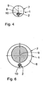
- the design of the probe 1 after Fig. 4 is different from the one after the Fig. 1 to 3 only in that by the probe after Fig. 4 the gas space longitudinal axis 9 does not coincide with the fiber axis 10 in the gas space 8, but is parallel to this. As a result, the gas space 8 in the execution after Fig. 4 a larger coherent free volume on, in which other components, such as other sensors, can be accommodated.
- the Fig. 5 and 6 show a catheter 14 with a further embodiment of a probe 1.
- the catheter 14 will be described below only where it differs from what was described above in connection with the Fig. 1 to 4 already executed. Components which correspond to those described above with reference to Fig. 1 to 4 have already been described, bear the same reference numbers and are described only where they are in structure and function of the components according to the Fig. 1 to 4 differ.
- the catheter 14 has a housing 15 .. This is in the illustrated embodiment of titanium, but can also be made of a different material.
- the housing 15 is integrally and structurally subdivided into a distal housing section 16, a housing middle section 17 and a proximal housing section 18. At its distal end, the distal housing section 16 is covered by an atraumatic catheter tip 19.
- the catheter tip 19 extends peripherally of the distal housing section 16 over in the membrane tube 11 of the membrane. 7
- the catheter tip 19 constitutes a sealing cover of the diaphragm 7.
- a proximal peripheral end portion 20 of the diaphragm 7 is pushed onto a circumferential step 21 of the housing middle section 17.
- the outer diameter of the circumferential step 21 is slightly larger than the inner diameter of the membrane tube 11.
- annular space 22 which is part of the gas space 8 and through openings 23 with a cylindrical interior in the distal housing portion 16, which is also part of the gas space 8, is in communication.
- the distal fiber portion 6 of the optical fiber 2 with the dye 5 is inserted into this interior.
- the fiber 2 first passes through a sealing body 24, which is inserted into the housing center section 17 and can be made, for example, from silicone rubber.
- the fiber 2 passes through a cylindrical interior of the proximal housing section 18 and a catheter tube 25. The latter is pushed onto a circumferential step 26, which is formed in the proximal housing section 18.
- An outer wall 27 of the sealing body 24 is arranged in a housing window in the housing center section 17 and is aligned with the surrounding outer wall of the housing center section 17.
- a pressure sensor 28 is arranged in the sealing body 24 in the sealing body 24, a pressure sensor 28 is arranged. Via a signal line 29 which extends through the sealing body 24, the proximal housing section 18 and the catheter tube 25, the pressure sensor 28 is connected to a central control and evaluation unit, not shown.
- a temperature sensor 30 is arranged in the interior. A proximal end of the temperature sensor 30 is inserted tightly into the sealing body 24. Via a signal line 31, the temperature sensor 30 is in communication with the central control and evaluation unit. The signal line 31 also passes through the sealing body 24, the proximal housing section 18 and the catheter tube 25.
- the function of the catheter 14 is described below only where there is a difference to the use of the probe 1 after the Fig. 1 to 4 is present.
- the catheter 14 is brought into the measuring position in the patient, with the probe 1 according to what is above in connection with the execution of the Fig. 1 to 4 was carried out, measured the oxygen content of the catheter 14 surrounding biological tissue.
- the pressure which the biological tissue exerts on the pressure sensor 28 via the outer wall 27 and the temperature in the gas space 8 via the temperature sensor 30 are measured via the pressure sensor 28.
- the measured values are fed via the signal lines 29 and 31 to the central control and evaluation unit, to which the light source and the light sensor of the probe 1 are also connected.
- the temperature in the gas space 8 which measures the temperature sensor 30, corresponds to the temperature of the biological tissue surrounding the distal housing section 16 of the catheter 14.
- This temperature compensation accomplished and the basis for the rapid temperature measurement is water vapor, which penetrates the membrane tube 11 and penetrates into the gas space 8. Due to the temperature measured via the temperature sensor 30, the temperature dependence of the water vapor partial pressure in the measurement of the oxygen partial pressure via the optical fiber 2 can be taken into account.
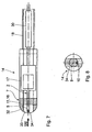
- FIGS. 7 and 8 show a further embodiment of a catheter with a probe for measuring the oxygen content in biological tissue.
- Components already described above with reference to the Fig. 1 to 6 have the same reference numerals and will not be explained again in detail.
- the catheter 14 after the FIGS. 7 and 8 different from that after the Fig. 5 and 6 mainly by the design of the membrane 7 and the arrangement of the sensors.
- a catheter tip 32 is in the execution of the FIGS. 7 and 8 not as in the execution after the Fig. 5 and 6 made of solid material, but has an inner recess 33 which is part of the gas space 8.
- the recess 33 is covered by a front-side membrane portion 34, which is made of the same material and has the same material thickness as the membrane tube 11.
- the membrane portion 34 merges seamlessly into the surrounding portions of the catheter tip 32 at the edge, so that the membrane portion 34 together forms the atraumatic catheter tip with these surrounding sections.
- the membrane portion 34 is in the end view of FIG. 8 indicated by a parallel hatching.
- the optical fiber 2 with the dye 5 is in the embodiment of the FIGS. 7 and 8 pushed into the recess 33 of the catheter tip 32.
- the gas space longitudinal axis 9 does not coincide with the fiber axis 10, but is spaced therefrom and parallel.
- the temperature sensor 30 is in the execution of the FIGS. 7 and 8 not in the gas space 8, but arranged in the proximal housing portion 18.
- the function of the catheter 14 after the FIGS. 7 and 8 corresponds to that of the catheter after the Fig. 5 and 6 .
- catheter 14 after the FIGS. 7 and 8 the temperature in the region of the proximal housing portion 18 is measured, so that a correct consideration of the temperature dependence of the water vapor partial pressure assumes that the temperature of the biological tissue in the region of the proximal housing section 18 coincides with the temperature in the region of the distal housing section 16.
- platinum or ruthenium complexes can be used as dye 5 platinum or ruthenium complexes.
- Typical fluorescence lifetimes of platinum complexes are 60 ⁇ s at 0% air saturation and 20 ⁇ s at 100% air saturation.
- Typical fluorescence lifetimes of ruthenium complexes are about 6 ⁇ s at 0% air saturation and about 4 ⁇ s at 100% air saturation.
Landscapes
- Health & Medical Sciences (AREA)
- Life Sciences & Earth Sciences (AREA)
- Physics & Mathematics (AREA)
- Pathology (AREA)
- General Health & Medical Sciences (AREA)
- Animal Behavior & Ethology (AREA)
- Engineering & Computer Science (AREA)
- Biomedical Technology (AREA)
- Heart & Thoracic Surgery (AREA)
- Medical Informatics (AREA)
- Molecular Biology (AREA)
- Surgery (AREA)
- Biophysics (AREA)
- Optics & Photonics (AREA)
- Public Health (AREA)
- Veterinary Medicine (AREA)
- Spectroscopy & Molecular Physics (AREA)
- Nuclear Medicine, Radiotherapy & Molecular Imaging (AREA)
- Chemical & Material Sciences (AREA)
- Analytical Chemistry (AREA)
- Biochemistry (AREA)
- General Physics & Mathematics (AREA)
- Immunology (AREA)
- Measurement Of The Respiration, Hearing Ability, Form, And Blood Characteristics Of Living Organisms (AREA)
- Investigating, Analyzing Materials By Fluorescence Or Luminescence (AREA)
- Pharmaceuticals Containing Other Organic And Inorganic Compounds (AREA)
- Investigating Or Analysing Materials By The Use Of Chemical Reactions (AREA)
Description
- Die Erfindung betrifft eine Sonde zur Messung des Sauerstoffgehaltes in biologischem Material nach dem Oberbegriff des Anspruchs 1 sowie nach dem Oberbegriff des Anspruchs 9. Ferner betrifft die Erfindung einen Katheter mit einer derartigen Sonde.
- Die Messung von Sauerstoff ist insbesondere im Bereich der Medizin von großem Interesse. Hierbei ist insbesondere die in vivo-Erfassung des gelösten, nicht an Hämoglobin gebundenen Sauerstoffs für die Beurteilung der Versorgung des biologischen Materials, insbesondere des Gewebes, von Bedeutung. Weitere Beispiele für hinsichtlich des Sauerstoffgehaltes zu untersuchendes biologisches Material sind Körperflüssigkeiten wie Blut oder Liquor. Eine entscheidende Größe ist dabei der Sauerstoffpartialdruck, der im untersuchten Gewebe herrscht. Der Partialdruck des in der interstitiellen Flüssigkeit physikalisch gelösten Sauerstoffes entspricht der Verfügbarkeit von Sauerstoff auf zellulärer Ebene. Insbesondere im Bereich der kardiovaskulären sowie der neurochirurgischen Anwendung als auch im Bereich der Transplantationsmedizin findet die Erfassung des Gewebesauerstoffs Anwendung. Hierbei werden zur Messung vor allem Katheter eingesetzt, die spezifisch auf Sauerstoff reagierende Sensorsysteme bzw. Sonden umfassen.
- Eine Sonde der eingangs genannten Art ist bekannt aus der
WO 93/05702 A1 US 5,673,694 , derUS 5,995,208 , derUS 5,579,774 sowie den dort zitierten Veröffentlichungen. Eine weitere faseroptische Sauerstoffsonde ist bekannt aus J.I. Peterson et al., Anal. Chem. 1984, 56, 62-67. Weitere faseroptische Sonden sind bekannt aus derUS 4,752,115 A ,US 5,142,155 A undUS 4,861,727 A . - Eine Sonde gemäß Oberbegriff der Ansprüche 1 und 9 ist bekannt aus
US-A-47 37 343 . - Eine bekannte Messtechnik zur faseroptischen Messung des Partialdrucks des physikalisch gelösten, also freien Sauerstoffs, ist das dynamische Sauerstoffquenchen. Hierbei wird ein in einer Matrix eingebetteter Fluoreszenzfarbstoff, zum Beispiel ein Platinkomplex, am distalen Ende der optischen Faser angebracht. Der Fluoreszenzfarbstoff wird über die Faser optisch angeregt, meist durch Laserstrahlung, welche auf Absorptionsbanden des Farbstoffs abgestimmt ist. Die so angeregten Farbstoffmoleküle gehen mit zeitlicher Verzögerung, z.B. im Bereich zwischen 1 und 60 µs, unter Aussenden Lichtes gleicher oder rotverschobener Wellenlänge in den Grundzustand über. In Gegenwart von Sauerstoff kann dieser Übergang durch Stoßprozesse auch strahlungslos in den Grundzustand erfolgen.
- Hierdurch nimmt die Intensität des durch die Faser zurückgestrahlten Lichtes ab. Diese Reduktion ist dem freien Sauerstoff in der direkten Umgebung um den Fluoreszenzfarbstoff proportional. Die bekannten faseroptischen Sensoren sind gegenüber Streulicht und intensitätsbeeinflussenden Faktoren wie Haarrissen oder einer Faserkrümmung äußerst sensibel. Diese Sensibilität kann verringert werden, wenn mit Hilfe einer Lock-In-Technik die Phasenverschiebung des vom Fluoreszenzfarbstoff zurückgestrahlten Lichts gegenüber dem eingestrahlten Licht gemessen wird. Hierbei wird ausgenutzt, dass langlebige Fluoreszenzzustände statistisch anfälliger für die strahlungslosen Stoßprozesse des dynamischen Sauerstoffquenchens sind. Eine, wenn auch verringerte Sensibilität bekannter faseroptischer Sensoren gegenüber Streulicht und intensitätsbeeinflussenden Faktoren liegt allerdings auch dann vor, wenn mit Lock-In-Technik gemessen wird. Zudem hat sich herausgestellt, dass in derselben Geweberegion mit den bekannten faseroptischen Sensoren sehr unterschiedliche Messwerte des freien Sauerstoffgehaltes resultieren, was die Interpretation einer Einzelmessung nahezu unmöglich macht.
- Es ist daher eine Aufgabe der vorliegenden Erfindung, eine Sonde der eingangs genannten Art derart weiterzubilden, dass die Sensibilität der Faser am Messort gegenüber störenden Umgebungseinflüssen verringert ist und die Interpretationsmöglichkeiten der Messergebnisse verbessert sind.
- Diese Aufgabe ist erfindungsgemäß gelöst durch eine Sonde mit den im Kennzeichnungsteil des Anspruchs 1 und 9 angegebenen Merkmalen.
- Erfindungsgemäß wurde erkannt, dass die Schaffung eines den distalen Faserabschnitt umgebenden Gasraumes durch eine sauerstoffdurchlässige und gleichzeitig flüssigkeitsundurchlässige Membran das Messvolumen um den Farbstoff herum vorteilhaft vergrößert. Das Messvolumen ist nun nicht mehr reduziert auf die unmittelbare Material- bzw. Gewebeumgebung um den Farbstoff herum, sondern erweitert auf die äußere Umgebung der den Gasraum vorgebenden Membran. Der im Gasraum sich bildende Sauerstoff-Partialdruck ist somit ein Maß für das Mittel des freien Sauerstoffgehaltes an der Außenfläche der den Gasraum vorgebenden Membran. Die Vergrößerung des sensitiven Volumens führt damit zu einer medizinisch gut verwertbaren Aussage über die lokale, nicht aber punktuelle Sauerstoffversorgung im die Sonde umgebenden biologischen Gewebe. Damit kann der Gewebezustand besser beurteilt werden als bei der rein punktuellen Messung, die bei den faseroptischen Messverfahren des Standes der Technik gegeben ist. Gleichzeitig schützt die Membran den distalen Faserabschnitt im Gasraum, sodass dort die Gefahr einer Störung der Messung verhindert ist. Die Robustheit des erfindungsgemäßen faseroptischen Sensors wird durch Einsatz der vorstehend erwähnten Lock-In-Technik noch weiter erhöht. Mit dem faseroptischen Sensor kann der Sauerstoffgehalt von Gewebe, aber auch von anderem biologischen Material, zum Beispiel von Körperflüssigkeiten wie Blut oder Liquor, vermessen werden. Beim sauerstoffsensitiven Farbstoff kann es sich zum Beispiel um einen Platinkomplex oder um einen Rutheniumkomplex handeln. Der sauerstoffsensitive Farbstoff liegt als Beschichtung vor oder ist zumindest abschnittsweise in die Membranwand eingearbeitet. Die Anordnung des Farbstoffes muss dabei natürlich so sein, dass ein möglichst direkter optischer Weg zwischen den Farbstoffmolekülen und der distalen Endfläche der Faser vorhanden ist. Vorzugsweise ist daher der Farbstoff als direkte Beschichtung auf die distale Endfläche der Faser vorgesehen. Gegenüber einer vollständigen Füllung eines der distalen Faser-Endfläche vorgelagerten Volumens mit Farbstoff hat die erfindungsgemäße Anordnung des Farbstoffs als Beschichtung oder Membranwandbestandteil den Vorteil, dass eine Lichtantwort des Farbstoffs nicht durch andere im Volumen enthaltene Farbstoffmoleküle unerwünscht absorbiert wird und damit verloren geht.
- Eine einheitliche Membranstärke nach Anspruch 2 verhindert eine zeitliche Verschmierung des Partialdruck-Messsignales, da die freien Sauerstoffmoleküle eine einheitliche Diffusionszeit durch die Membran haben. Es resultiert eine homogene Sensorcharakteristik. Eine einheitliche Membranstärke bedeutet nicht, dass die Membranstärke über die gesamte Fläche der Membran exakt konstant ist. Geringfügige Abweichungen von einer mittleren Membranstärke, welche die angesprochene homogene Sensorcharakteristik in der Praxis nicht beeinflussen, können hingenommen werden. Derartige tolerable Abweichungen bewegen sich beispielsweise im Bereich von 200 µm. Ein sauerstoffsensitiver Farbstoff mit einer langen Fluoreszenzlebensdauer kann störende Effekte, die von Abweichungen der Membranstärke herrühren, ausgleichen. Daher ist für eine homogene Sensorcharakteristik zum Beispiel ein Platinkomplex mit einer Fluoreszenzlebensdauer bis zu 60 µs von Vorteil.
- Ein Gasraum nach Anspruch 3 lässt sich mit einer kostengünstig herstellbaren Membran realisieren. Wenn die Gasraum-Längsachse parallel zur Faserachse und von dieser beabstandet ist, kann der Gasraum mit einem großen zusammenhängenden freien Volumen gestaltet werden, welches sich zur Anordnung weiterer Komponenten, insbesondere von Sensoren, der Sonde eignet. Wenn die Achsen zusammenfallen, resultiert ein rotationssymmetrischer Aufbau, der insbesondere Herstellungsvorteile bietet. Bei zusammenfallenden Achsen bietet sich insbesondere eine Ausgestaltung an, bei der die distale Endfläche der Faser mit dem Farbstoff im Gasraum zentriert vorliegt, so dass im Bezug auf freien Sauerstoff, der durch die Membran diffundiert, eine Diffusionslängensymmetrie vorliegt, was die Messqualität erhöhen kann.
- Eine Membran nach Anspruch 4 lässt sich einfach herstellen, da der Membranschlauch z. B. durch Ablängen eines Endlosschlauchs gebildet werden kann.
- Materialien nach Anspruch 5 haben sich hinsichtlich der Eigenschaften Sauerstoffdurchlässigkeit und Flüssigkeitsundurchlässigkeit als für die Anwendung in der Sonde gut geeignet herausgestellt.
- Eine Membran nach Anspruch 6 passt sich gut an das sie umgebende Gewebe an, sodass eine Verfälschung der Messung verhindert ist.
- Eine Luftfüllung nach Anspruch 7 verhindert, dass sich die Gaszusammensetzung bei einer Lagerung der Sonde vor deren Einsatz verändert. Altemativ ist es möglich, ein Gas oder ein Gasgemisch vor Einsatz der Sonde einzufüllen, welches aus derart großen Molekülen besteht, dass diese die sauerstoffdurchlässige Membran nicht nach außen durchdringen können. Auch in diesem Fall wird eine Gasraumfüllung für eine Lagerung der Sonde vor deren Einsatz erzielt, die sich nicht verändert.
- Eine Wasserdampfdurchlässigkeit nach Anspruch 8 ermöglicht aufgrund der erhöhten Wärmekapazität des Gases im Gasraum durch Wasserdampf, der dort eindringen kann, eine schnellere Anpassung der sich im Gasraum befindlichen Sensoren an die Umgebungstemperatur. Hierdurch ist innerhalb des Gasraums eine verlässliche Temperaturmessung möglich, ohne dass lange auf die Einpendelung eines thermischen Gleichgewichts gewartet werden muss. Wird daher auf eine hohe Wasserdampfdurchlässigkeit Wert gelegt, kann die Membran insbesondere aus Tetrafluorethylen-Hexafluorpropylen-Copolymer (FEP) ausgeführt sein. Auch eine Membran aus Polyethylen (PE) weist eine, im Vergleich zu FEP allerdings geringere, Wasserdampfdurchlässigkeit auf.
- Die Sonde nach Anspruch 9 kann diejenigen Merkmale aufweisen, die vorstehend im Zusammenhang mit den Ansprüchen 2 bis 8 erläutert wurden.
- Eine weitere Aufgabe ist es, einen Katheter anzugeben, mit dem eine aussagekräftige Messung durch eine erfindungsgemäße Sonde ermöglicht ist.
- Diese Aufgabe ist erfindungsgemäß gelöst durch einen Katheter mit den im Anspruch 10 angegebenen Merkmalen.
- Der Temperatursensor erlaubt eine Kompensation einer thermischen Abhängigkeit der Sauerstoffgehaltsmessung. Der vorzugsweise vorhandene Drucksensor ermöglicht eine zusätzliche Druckmessung, die in Kombination mit der Sauerstoffgehaltsmessung wertvolle gewebespezifische Informationen liefert. Durch eine derartige Kombinationsmessung, bei der Sauerstoffgehalt und Druck gemessen werden, lässt sich zum Beispiel prüfen, inwieweit der Sauerstoffgehalt und der Druckverlauf in ihrer Dynamik korreliert sind. Es kann also eine Korrelation des Gewebedrucks und des Sauerstoffpartialdrucks ermittelt werden. Das Erfassen verschiedener physiologischer Parameter über einen einzigen Katheter reduziert das Infektions-und Blutungsrisiko im Vergleich zur Applikation mehrerer einzelner Katheter über jeweils getrennte Katheterzugänge. Die vorzugsweise teilweise metallische Katheterspitze ermöglicht deren Erkennen in bildgebenden Verfahren, zum Beispiel bei der CT. Dadurch wird die gezielte Platzierung in das gewünschte Areal ermöglicht. Dies ist insbesondere notwendig zur Differenzierung zwischen einer lokalen oder globalen Situation bei pathophysiologischen Ereignissen mit erniedrigten Sauerstoffpartialdruckwerten, wie zum Beispiel bei Blutungen im Stichkanal, Schwellung im Bereich der Katheterlage oder bei einer lokalen Ischämie. Weitere Vorteile des Katheters sind diejenigen, die oben im Zusammenhang mit der Sonde schon erwähnt wurden.
- Ein Temperatursensor nach Anspruch 11 erlaubt eine gute Kompensation der Temperaturabhängigkeit der faseroptischen Sauerstoffgehaltsmessung, da die Temperatur genau dort gemessen wird, wo auch die Sauerstoffgehaltsmessung stattfindet. Durch die permanente Temperaturkorrektur der Sauerstoffgehaltsmessung sind die Werte auch bei Hypo- und Hyperthermie verlässlich.
- Eine Katheterspitze nach Anspruch 12 führt zu einer Reduktion der Einzelteile des Katheters.
- Ausführungsbeispiele der Erfindung werden nachfolgend anhand der Zeichnung näher erläutert. In dieser zeigen:
- Fig. 1
- im schematischen Längsschnitt eine Sonde zur Messung des Sauerstoffgehaltes in biologischem Gewebe;
- Fig. 2
- eine zu
Fig. 1 ähnliche Darstellung der Sonde, bei der ein distaler Faserabschnitt einer optischen Faser weiter in einen durch eine Membran vorgegebenen Gasraum eingeschoben ist; - Fig. 3
- einen Schnitt gemäß Linie III-III in
Fig. 2 ; - Fig. 4
- einen zu
Fig. 3 ähnlichen Schnitt durch eine weitere Ausführungsform einer Sonde; - Fig. 5
- einen Längsschnitt durch einen Katheter mit einer weiteren Ausführung einer Sonde zur Messung des Sauerstoffgehalts in biologischem Gewebe;
- Fig. 6
- schematisch einen Schnitt gemäß Linie VI-VI in
Fig. 5 ; - Fig. 7
- einen zu
Fig. 5 ähnlichen Schnitt durch eine weitere Ausführungsform eines Katheters; und - Fig. 8
- eine Stirnansicht gemäß Sichtpfeil VIII in
Fig. 7 . - Die
Fig. 1 bis 3 zeigen eine erste Ausführungsform einer Sonde zur Messung des Sauerstoffgehalts in biologischem Gewebe. Die Sonde 1 kann Bestandteil eines Katheters z. B. nach Art desjenigen sein, der inFig. 5 dargestellt ist. - Die Sonde 1 weist eine optische Faser 2 auf. Ein proximales Ende 3, welches dem zu vermessenden biologischen Gewebe abgewandt ist, ist an eine Lichtquelle einerseits und an einen Lichtsensor andererseits optisch ankoppelbar. Bei der optischen Faser 2 kann es sich um eine Einzelfaser oder um ein Faserbündel handeln.
- An einer distalen Endfläche 4 der optischen Faser 2, die dem zu vermessenden biologischen Gewebe zugewandt ist, ist ein sauerstoffsensitiver Farbstoff 5 angeordnet. Der Farbstoff 5 ist an die distale Endfläche 4 der optischen Faser 2 optisch angekoppelt. Die distale Endfläche 4 ist mit dem Farbstoff 5 beschichtet. Ein distaler Faserabschnitt 6 einschließlich der distalen Endfläche 4 mitsamt dem Farbstoff 5 ist umschlossen von einer sauerstoffdurchlässigen, flüssigkeitsundurchlässigen Membran 7. Die Membran 7 ist wasserdampfdurchlässig ausgeführt. Letztere gibt im umschlossenen Bereich einen Gasraum 8 vor, der die distale Endfläche 4 mit dem Farbstoff 5 umgibt. Alternativ zu einer Beschichtung der distalen Endfläche 4 mit dem Farbstoff 5 ist es möglich, die Innenwand der Membran 7 zumindest bereichsweise mit dem Farbstoff 5 zu beschichten. Als beschichtete Bereiche werden dabei diejenigen ausgewählt, die von der distalen Endfläche 4 "gesehen" werden, zu denen also ein direkter optischer Weg von der distalen Endfläche 4 aus vorhanden ist. Bei einer weiteren Variante ist es möglich, den Farbstoff 5 in die Wandung der Membran 7 einzuarbeiten.
- Die Membran 7 hat dort, wo sie den Gasraum 8 vorgibt, eine einheitliche Stärke. Die zulässige Abweichung der Membranstärke von einem Vorgabewert hängt von der gewünschten Messdynamik des Sauerstoffpartialdruckes ab. Für Messungen im Hirngewebe haben sich zum Beispiel Abweichungen von 200 µm als tolerierbar herausgestellt. Bei der Sonde nach den
Fig. 1 bis 3 hat der Gasraum 8 die Gestalt eines Zylinders. Eine Gasraum-Längsachse 9 fällt mit einer Faserachse 10 zumindest im distalen Faserabschnitt 6 zusammen. - Bei der Ausführung nach den
Fig. 1 bis 3 ist die Membran 7 aus Silikonkautschuk. Alternativ kann die Membran 7 auch aus einem der Materialien Polyethylen (PE), Teflon (PTFE) oder Tetrafluorethylen-Hexafluorpropylen-Copolymer (FEP) sein. Die Membran 7 ist derart flexibel, dass sie unter Einfluss eines im Gasraum 8 vorliegenden Gasdrucks verformbar ist. Die Gestalt des Gasraums 8 kann sich also an den jeweils dort vorliegenden Gasdruck in Abhängigkeit vom Umgebungsdruck anpassen. - Je nach Anwendung kann die Sonde 1 mit unterschiedlichen Relativpositionen der Faser 2 zur Membran 7 vorliegen. In der Position nach
Fig. 1 ist die Faser 2 lediglich ein kurzes Stück weit in den Gasraum 8 eingeschoben, sodass der von der Membran 7 umschlossene distale Faserabschnitt 6 im Vergleich zur Länge des Gasraums 8 kurz ist. In der Position nachFig. 2 ist die Faser 2 weiter in den Gasraum 8 eingeschoben, sodass der distale Faserabschnitt 6 in etwa halb so lang ist wie der Gasraum 8. In der Position nachFigur 2 liegt die distale Endfläche 4 mit der Faser 5 symmetrisch zentral im Gasraum 8, so dass in Bezug auf freien Sauerstoff, der durch die Membran 7 diffundiert, eine Diffusionslängensymmetrie vorliegt. - Zunächst wird die Sonde 1, gegebenenfalls mit samt einem diese aufweisenden Katheter, in vivo beim Patienten in Messposition gebracht. Der Gasraum 8 ist vor dem Einsatz der Sonde 1 mit Luft gefüllt. Sowohl die Lichtquelle als auch der Lichtsensor werden an die Faser 2 proximal angekoppelt. Die Membran 7 ist nach außen hin vom biologischen Gewebe des Patienten umschlossen. Freier, das heißt nicht an Hämoglobin gebundener Sauerstoff, kann die Membran 7 von außen her durchdringen, also in den Gasraum 8 eindringen. Da der Gasraum 8 flüssigkeitsdicht nach außen abgeschlossen ist, kann weder Flüssigkeit noch Gewebe in den Gasraum 8 eindringen.
- Der Farbstoff 5 ist auf die Wellenlänge des eingekoppelten Lichtes so abgestimmt, dass als Folge des in den Farbstoff 5 eingekoppelten Lichtes unter Einfluss der im Gasraum 8 vorliegenden Sauerstoffmoleküle vom Farbstoff 5 in die optische Faser 2 zurückgekoppeltes Licht in seiner vom Lichtsensor messbaren Menge von der Konzentration des freien Sauerstoffs im Gasraum 8 abhängt. Durch die einheitliche Stärke der den Gasraum 8 vorgebenden Membran 7 ist entsprechend eine einheitliche Eindringzeit des freien Sauerstoffs vom die Membran 7 umgebenden biologischen Gewebe in den Gasraum 8 gewährleistet. Messfehler aufgrund unterschiedlicher Eindringzeiten können daher nicht entstehen.
- Mithilfe des Lichtsensors wird die Menge des vom Farbstoff 5 in die Faser 2 zurückgekoppelten Lichtes als Antwort auf das von der Lichtquelle in die Faser 2 eingekoppelte Licht gemessen. Diese zurückgekoppelte Lichtmenge ist ein Maß für den Sauerstoffgehalt im Gasraum 8 und damit ein Maß für den im die Membran 7 umgebenden biologischen Gewebe nicht an Hämoglobin gebundenen, also freien Sauerstoff. Alternativ ist es möglich, die Phasenverschiebung des zurückgekoppelten Lichtes in Abhängigkeit von der Phase des eingekoppelten Lichtes zum Beispiel mit Hilfe von Lock-In-Technik zu messen. Da langlebige Zustände des Farbstoffs 5 statistisch anfälliger für einen sauerstoffinduzierten strahlungslosen Übergang in den Grundzustand durch einen Stoßprozess sind, verschiebt sich die mittlere Lebensdauer der Fluoreszenzzustände, die zum zurückgekoppelten Licht beitragen, was wiederum zu einer messbaren Phasenverschiebung gegenüber dem eingestrahlten Signal, welches als Lock-In-Referenz genutzt werden kann, führt.
- Bei der Ausführung nach den
Fig. 1 bis 3 ist die Membran 7 einstückig ausgeführt. Das Material der Membran 7 dichtet im Bereich des Fasereintritts in den Gasraum 8 gegen die optische Faser 2 ab. - Bei einer Variante der Sonde 1, die nachfolgend der Einfachheit halber ebenfalls anhand der
Fig. 1 bis 3 beschrieben wird, umfasst die Membran 7 einen Membranschlauch 11, der die Mantelwand des zylindrischen Gasraums 8 vorgibt. Ein faserabgewandtes, stirnseitiges Ende des Membranschlauchs 11 weist einen Dichtungsdeckel 12 auf. Der Dichtungsdeckel 12 kann aus dem gleichen Material wie der Membranschlauch 11 sein. Alternativ ist es möglich, den Dichtungsdeckel 12 aus einem anderen, insbesondere vollkommen fluidundurchlässigen, Material als den Membranschlauch 11 herzustellen, da es ausreicht, wenn der Membranschlauch 11 sauerstoffdurchlässig ist. An der der Faser zugewandten Seite ist der Membranschlauch 11 gegen die Faser 2 mittels eines Dichtungsrings 13 abgedichtet, der aus dem gleichen Material sein kann wie der Dichtungsdeckel 12. - Die Ausführung der Sonde 1 nach
Fig. 4 unterscheidet sich von derjenigen nach denFig. 1 bis 3 lediglich dadurch, dass bei der Sonde nachFig. 4 die Gasraum-Längsachse 9 nicht mit der Faserachse 10 im Gasraum 8 zusammenfällt, sondern parallel zu dieser ist. Dadurch weist der Gasraum 8 bei der Ausführung nachFig. 4 ein größeres zusammenhängendes freies Volumen auf, in dem weitere Komponenten, z.B. weitere Sensoren, untergebracht werden können. - Die
Fig. 5 und6 zeigen einen Katheter 14 mit einer weiteren Ausführung einer Sonde 1. Der Katheter 14 wird nachfolgend nur dort beschrieben, wo er sich von dem unterscheidet, was vorstehend im Zusammenhang mit denFig. 1 bis 4 schon ausgeführt wurde. Komponenten, die denjenigen entsprechen, die vorstehend unter Bezugnahme auf dieFig. 1 bis 4 schon beschrieben wurden, tragen die gleichen Bezugsziffern und werden nur dort beschrieben, wo sie sich in Aufbau und Funktion von den Komponenten nach denFig. 1 bis 4 unterscheiden. Der Katheter 14 hat ein Gehäuse 15.. Dieses ist bei der dargestellten Ausführung aus Titan, kann aber auch aus einem anderen Werkstoff gefertigt sein. Das Gehäuse 15 ist einstückig und strukturell unterteilt in einen distalen Gehäuseabschnitt 16, einen Gehäuse-Mittelabschnitt 17 und einen proximalen Gehäuseabschnitt 18. An seinem distalen Ende wird der distale Gehäuseabschnitt 16 abgedeckt von einer atraumatischen Katheterspitze 19. Die Katheterspitze 19 geht umfangseitig des distalen Gehäuseabschnitts 16 über in den Membranschlauch 11 der Membran 7. - Die Katheterspitze 19 stellt einen Dichtungsdeckel der Membran 7 dar. Ein proximaler Umfangs-Endabschnitt 20 der Membran 7 ist auf eine Umfangsstufe 21 des Gehäuse-Mittelabschnitts 17 aufgeschoben. Der Außendurchmesser der Umfangsstufe 21 ist etwas größer als der Innendurchmesser des Membranschlauchs 11.
- Zwischen dem Membranschlauch 11 und dem distalen Gehäuseabschnitt 16 liegt ein Ringraum 22 vor, der Teil des Gasraums 8 ist und über Durchbrechungen 23 mit einem zylindrischen Innenraum im distalen Gehäuseabschnitt 16, der ebenfalls Teil des Gasraums 8 ist, in Verbindung steht. In diesen Innenraum ist der distale Faserabschnitt 6 der optischen Faser 2 mit dem Farbstoff 5 eingeschoben. Im weiteren Verlauf durchtritt die Faser 2 zunächst einen Dichtkörper 24, der in den Gehäuse-Mittelabschnitt 17 eingesetzt ist und zum Beispiel aus Silikonkautschuk gefertigt sein kann. Im weiteren Verlauf durchtritt die Faser 2 einen zylindrischen Innenraum des proximalen Gehäuseabschnitts 18 sowie einen Katheterschlauch 25. Letzterer ist auf eine Umfangsstufe 26, die im proximalen Gehäuseabschnitt 18 ausgebildet ist, aufgeschoben.
- Eine Außenwand 27 des Dichtkörpers 24 ist in einem Gehäusefenster im Gehäuse-Mittelabschnitt 17 angeordnet und fluchtet mit der sie umgebenden Außenwand des Gehäuse-Mittelabschnitts 17. Im Dichtkörper 24 ist ein Drucksensor 28 angeordnet. Über eine Signalleitung 29, die durch den Dichtkörper 24, den proximalen Gehäuseabschnitt 18 sowie den Katheterschlauch 25 verläuft, steht der Drucksensor 28 mit einer nicht dargestellten zentralen Steuer- und Auswerteeinheit in Verbindung.
- Wie bei der Ausführung nach
Fig. 4 fällt bei der Sonde 1 nachFig. 5 und6 die Gasraum-Längsachse 9 nicht mit der Faserachse 10 zusammen, sodass im vom distalen Gehäuseabschnitt vorgegebenen Innenraum ein großes zusammenhängendes freies Volumen vorliegt. Dort ist im Innenraum ein Temperatursensor 30 angeordnet. Ein proximales Ende des Temperatursensors 30 ist dicht in den Dichtkörper 24 eingesetzt. Über eine Signalleitung 31 steht der Temperatursensor 30 mit der zentralen Steuer- und Auswerteeinheit in Verbindung. Die Signalleitung 31 durchläuft ebenfalls den Dichtkörper 24, den proximalen Gehäuseabschnitt 18 sowie den Katheterschlauch 25. - Die Funktion des Katheters 14 wird nachfolgend nur dort beschrieben, wo ein Unterschied zum Einsatz der Sonde 1 nach den
Fig. 1 bis 4 vorliegt. Nachdem der Katheter 14 in die Messposition im Patienten gebracht ist, wird mit der Sonde 1 entsprechend dem, was oben im Zusammenhang mit der Ausführung nach denFig. 1 bis 4 ausgeführt wurde, der Sauerstoffgehalt des den Katheter 14 umgebenden biologischen Gewebes gemessen. Gleichzeitig wird über den Drucksensor 28 der Druck, den das biologische Gewebe über die Außenwand 27 auf den Drucksensor 28 ausübt, sowie die Temperatur im Gasraum 8 über den Temperatursensor 30 gemessen. Die Messwerte werden über die Signalleitungen 29 und 31 an die zentrale Steuer- und Auswerteeinheit, an die auch die Lichtquelle und der Lichtsensor der Sonde 1 angeschlossen sind, zugeleitet. Nach Einstellung des thermischen Gleichgewichts entspricht die Temperatur im Gasraum 8, die der Temperatursensor 30 misst, der Temperatur des den distalen Gehäuseabschnitt 16 des Katheters 14 umgebenden biologischen Gewebes. Diesen Temperaturausgleich bewerkstelligt und die Grundlage für die schnelle Temperaturmessung ist Wasserdampf, welcher den Membranschlauch 11 durchdringt und in dem Gasraum 8 eindringt. Aufgrund der über den Temperatursensor 30 gemessenen Temperatur kann die Temperaturabhängigkeit des Wasserdampfs-Partialdrucks bei der Sauerstoff-Partialdruckmessung über die optische Faser 2 berücksichtigt werden. - Die
Fig. 7 und 8 zeigen eine weitere Ausführung eines Katheters mit einer Sonde zur Messung des Sauerstoffgehaltes in biologischem Gewebe. Komponenten, die vorstehend schon unter Bezugnahme auf dieFig. 1 bis 6 beschrieben wurden, tragen die gleichen Bezugsziffern und werden nicht nochmals im Einzelnen erläutert. - Der Katheter 14 nach den
Fig. 7 und 8 unterscheidet sich von dem nach denFig. 5 und6 hauptsächlich durch die Gestaltung der Membran 7 und die Anordnung der Sensoren. Eine Katheterspitze 32 ist bei der Ausführung nach denFig. 7 und 8 nicht wie bei der Ausführung nach denFig. 5 und6 aus Vollmaterial ausgeführt, sondern weist eine innere Ausnehmung 33 auf, die Teil des Gasraums 8 ist. Distal wird die Ausnehmung 33 abgedeckt von einem stirnseitigen Membranabschnitt 34, der aus dem gleichen Material gefertigt ist und die gleiche Materialstärke aufweist wie der Membranschlauch 11. Der Membranabschnitt 34 geht randseitig nahtlos in die diesen umgebenden Abschnitte der Katheterspitze 32 über, sodass der Membranabschnitt 34 zusammen mit diesen umgebenden Abschnitten die atraumatische Katheterspitze bildet. Der Membranabschnitt 34 ist in der Stirnansicht derFigur 8 durch eine parallele Schraffur angedeutet. Die optische Faser 2 mit dem Farbstoff 5 ist bei der Ausführung nach denFig. 7 und 8 bis in die Ausnehmung 33 der Katheterspitze 32 eingeschoben. - Auch bei der Ausführung nach den
Fig. 7 und 8 fällt die Gasraum-Längsachse 9 nicht mit der Faserachse 10 zusammen, sondern ist zu dieser beabstandet und parallel. - Der Temperatursensor 30 ist bei der Ausführung nach den
Fig. 7 und 8 nicht im Gasraum 8, sondern im proximalen Gehäuseabschnitt 18 angeordnet. - Die Funktion des Katheters 14 nach den
Fig. 7 und 8 entspricht derjenigen des Katheters nach denFig. 5 und6 . Beim Katheter 14 nach denFig. 7 und 8 wird die Temperatur im Bereich des proximalen Gehäuseabschnitts 18 gemessen, sodass eine korrekte Berücksichtigung der Temperaturabhängigkeit des Wasserdampf-Partialdrucks voraussetzt, dass die Temperatur des biologischen Gewebes im Bereich des proximalen Gehäuseabschnitts 18 mit der Temperatur im Bereich des distalen Gehäuseabschnitts 16 übereinstimmt. - Als Farbstoff 5 können Platin- oder Rutheniumkomplexe eingesetzt werden. Typische Fluoreszenzlebensdauern von Platinkomplexen sind 60µs bei 0% Luftsättigung und 20 µs bei 100% Luftsättigung. Typische Fluoreszenzlebensdauem von Rutheniumkomplexen sind etwa 6 µs bei 0% Luftsättigung und etwa 4 µs bei 100% Luftsättigung.
Claims (12)
- Sonde (1) zur Messung des Sauerstoffgehaltes in biologischem Material- mit mindestens einer optischen Faser (2), welche proximal an eine Lichtquelle einerseits und an einen Lichtsensor andererseits optisch ankoppelbar ist,- mit einem sauerstoffsensitiven Farbstoff (5), welcher an einer distalen Endfläche (4) der Faser (2) angeordnet und an diese optisch angekoppelt ist,
dadurch gekennzeichnet, dass ein distaler Faserabschnitt (6) einschließlich der distalen Endfläche (4) mitsamt dem Farbstoff (5) umschlossen ist von einer sauerstoffdurchlässigen, flüssigkeitsundurchlässigen Membran (7), die im umschlossenen Bereich einen die distale Endfläche (4) mit dem Farbstoff (5) umgebenden Gasraum (8) vorgibt, wobei der Farbstoff (5)- als Beschichtung auf der distalen Endfläche (4) vorgesehen ist. - Sonde nach Anspruch 1, dadurch gekennzeichnet, dass die Stärke der Membran (7) dort, wo sie den Gasraum (8) vorgibt, einheitlich ist.
- Sonde nach Anspruch 1 oder 2, dadurch gekennzeichnet, dass der Gasraum (8) zumindest abschnittsweise die Gestalt eines Zylinders hat, dessen Längsachse (9) parallel zur Faserachse (10) im distalen Faserabschnitt (6) ist oder mit ihr zusammenfällt.
- Sonde nach einem der Ansprüche 1 bis 3, dadurch gekennzeichnet, dass die Membran (7) einen Membranschlauch (11) umfasst, dessen Enden (12, 13) zur Vorgabe des Gasraums (8) gegen Flüssigkeitsdurchtritt abgedichtet sind.
- Sonde nach einem der Ansprüche bis 4, dadurch gekennzeichnet, dass die Membran (7) aus einem der Materialien Silikonkautschuk, PE, PTFE oder FEP gebildet ist.
- Sonde nach einem der Ansprüche 1 bis 5, dadurch gekennzeichnet, dass die Membran (7) derart flexibel ist, dass sie unter Einfluss eines im Gasraum (8) vorliegenden Gasdrucks verformbar ist.
- Sonde nach einem der Ansprüche 1 bis 6, dadurch gekennzeichnet, dass der Gasraum (8) vor Einsatz der Sonde (1) mit Luft gefüllt ist.
- Sonde nach einem der Ansprüche 1 bis 7, dadurch gekennzeichnet, dass die Membran (7) wasserdampfdurchlässig ausgeführt ist.
- Sonde (1) zur Messung des Sauerstoffgehaltes in biologischem Material- mit mindestens einer optischen Faser (2), welche proximal an eine Lichtquelle einerseits und an einen Lichtsensor andererseits optisch ankoppelbar ist,- mit einem sauerstoffsensitiven Farbstoff (5),
dadurch gekennzeichnet, dass ein distaler Faserabschnitt (6) einschließlich der distalen Endfläche (4) umschlossen ist von einer sauerstoffdurchlässigen, flüssigkeitsundurchlässigen Membran (7), die im umschlossenen Bereich einen die distale Endfläche (4) umgebenden Gasraum (8) vorgibt, wobei der Farbstoff (5)- als Beschichtung auf der den Gasraum (8) begrenzenden Membran (7) vorgesehen ist oder in mindestens einen Abschnitt einer Wand der Membran (7) eingearbeitet ist. - Katheter (14)- mit einer Sonde (1) nach einem der Ansprüche 1 bis 9,- mit einem Temperatursensor (30) zur Messung der Temperatur des den Katheter umgebenden biologischen Materials,- sowie vorzugsweise mit einem Drucksensor (28) zur Messung des Drucks im den Katheter (14) umgebenden biologischen Materials.
- Katheter nach Anspruch 10, dadurch gekennzeichnet, dass der Temperatursensor (30) zumindest abschnittsweise im Gasraum (8) angeordnet ist.
- Katheter nach Anspruch 10 oder 11 unter Rückbeziehung auf Anspruch 4, dadurch gekennzeichnet, dass eine Katheterspitze (19; 32) die distale Abdichtung des Membranschlauches (11) der Membran (7) darstellt.
Priority Applications (2)
| Application Number | Priority Date | Filing Date | Title |
|---|---|---|---|
| SI200630483T SI1898779T1 (sl) | 2005-05-25 | 2006-05-17 | Sonda za merjenje vsebnosti kisika v biološkem tkivu in kateter s takšno sondo |
| PL06828784T PL1898779T3 (pl) | 2005-05-25 | 2006-05-17 | Sonda do pomiaru zawartości tlenu w tkance biologicznej oraz cewnik obejmujący tego rodzaju sondę |
Applications Claiming Priority (2)
| Application Number | Priority Date | Filing Date | Title |
|---|---|---|---|
| DE102005024578A DE102005024578A1 (de) | 2005-05-25 | 2005-05-25 | Sonde zur Messung des Sauerstoffgehaltes in biologischem Gewebe sowie Katheter mit einer derartigen Sonde |
| PCT/EP2006/004664 WO2007033707A1 (de) | 2005-05-25 | 2006-05-17 | Sonde zur messung des sauerstoffgehaltes in biologischem gewebe sowie katheter mit einer derartigen sonde |
Publications (2)
| Publication Number | Publication Date |
|---|---|
| EP1898779A1 EP1898779A1 (de) | 2008-03-19 |
| EP1898779B1 true EP1898779B1 (de) | 2009-09-09 |
Family
ID=36649465
Family Applications (1)
| Application Number | Title | Priority Date | Filing Date |
|---|---|---|---|
| EP06828784A Expired - Lifetime EP1898779B1 (de) | 2005-05-25 | 2006-05-17 | Sonde zur messung des sauerstoffgehaltes in biologischem gewebe sowie katheter mit einer derartigen sonde |
Country Status (19)
| Country | Link |
|---|---|
| US (1) | US20080194933A1 (de) |
| EP (1) | EP1898779B1 (de) |
| JP (1) | JP4951620B2 (de) |
| KR (1) | KR20080019204A (de) |
| CN (1) | CN100542478C (de) |
| AT (1) | ATE442080T1 (de) |
| AU (1) | AU2006294153B2 (de) |
| BR (1) | BRPI0611288B8 (de) |
| CA (1) | CA2609568A1 (de) |
| DE (2) | DE102005024578A1 (de) |
| DK (1) | DK1898779T3 (de) |
| ES (1) | ES2329176T3 (de) |
| IL (1) | IL187372A0 (de) |
| NO (1) | NO20076564L (de) |
| PL (1) | PL1898779T3 (de) |
| RU (1) | RU2401058C2 (de) |
| SI (1) | SI1898779T1 (de) |
| WO (1) | WO2007033707A1 (de) |
| ZA (1) | ZA200710016B (de) |
Families Citing this family (23)
| Publication number | Priority date | Publication date | Assignee | Title |
|---|---|---|---|---|
| US7455666B2 (en) | 2001-07-13 | 2008-11-25 | Board Of Regents, The University Of Texas System | Methods and apparatuses for navigating the subarachnoid space |
| AU2009206096A1 (en) * | 2008-01-15 | 2009-07-23 | Nicholas L. Taro | Method and apparatus for determining a deterioration of respiratory function |
| US20100204605A1 (en) * | 2009-02-12 | 2010-08-12 | Keimar, Inc. | Physiological parameter sensors |
| US20110092955A1 (en) | 2009-10-07 | 2011-04-21 | Purdy Phillip D | Pressure-Sensing Medical Devices, Systems and Methods, and Methods of Forming Medical Devices |
| US9298193B2 (en) * | 2010-10-22 | 2016-03-29 | Kenneth Susko | Optical probe containing oxygen, temperature, and pressure sensors and monitoring and control systems containing the same |
| BR112013009852A2 (pt) * | 2010-10-22 | 2016-11-22 | Kenneth Susko | sonda óptica contendo sensores de oxigênio, temperatura, e pressão e sistemas de monitoração e controle contendo os mesmos |
| WO2012103266A2 (en) * | 2011-01-25 | 2012-08-02 | Nvision Medical Corporation | Systems and methods for maintaining a narrow body lumen |
| CN102151123A (zh) * | 2011-04-13 | 2011-08-17 | 俞能旺 | 体内小脉管鉴别笔 |
| US11293866B2 (en) | 2012-03-22 | 2022-04-05 | John EASTMAN | Fiber optic analyte sensor |
| EP2976033A4 (de) * | 2013-03-19 | 2016-12-14 | Surgisense Corp | Vorrichtung, systeme und verfahren zur bestimmung der sauerstoffanreicherung von gewebe |
| US9316554B1 (en) * | 2014-12-23 | 2016-04-19 | Mocon, Inc. | Fiber optic analyte sensor with integrated in situ total pressure correction |
| PL235367B1 (pl) * | 2015-02-10 | 2020-06-29 | Politechnika Gdanska | Sposób bezinwazyjnego pomiaru glukozy we krwi i układ optoelektroniczny do bezinwazyjnego pomiaru glukozy we krwi |
| CN104905781A (zh) * | 2015-02-13 | 2015-09-16 | 林昌军 | 颅内生理参数采集装置和应用 |
| US10682498B2 (en) * | 2015-09-24 | 2020-06-16 | Silicon Microstructures, Inc. | Light shields for catheter sensors |
| US10641672B2 (en) | 2015-09-24 | 2020-05-05 | Silicon Microstructures, Inc. | Manufacturing catheter sensors |
| CN105686811B (zh) * | 2016-02-24 | 2019-02-05 | 南京航空航天大学 | 一种微创颅内多参数检测探头 |
| CN107582070B (zh) * | 2017-09-04 | 2020-06-02 | 长飞光纤光缆股份有限公司 | 一种介入式氧分压-温度复合探头 |
| CN109708685A (zh) * | 2017-10-26 | 2019-05-03 | 北京信息科技大学 | 一种基于光纤布拉格光栅传感器的探针运动控制方法 |
| RU198170U1 (ru) * | 2019-07-31 | 2020-06-22 | Общество с ограниченной ответственностью "Мониторинг" | Датчик для экспресс-анализа микроконцентраций кислорода в газовой среде |
| CN111103117B (zh) * | 2020-03-18 | 2024-10-22 | 中国空气动力研究与发展中心设备设计及测试技术研究所 | 一种低速风洞一体化方向动压组合探针测量装置 |
| WO2023283031A2 (en) * | 2021-06-15 | 2023-01-12 | Richard Postrel | Handheld device for early detection of disease, biological, chemical, and pathogenic agents |
| WO2023007813A1 (ja) * | 2021-07-30 | 2023-02-02 | テルモ株式会社 | 測定用プローブ、アダプタおよび測定システム |
| CN114451891A (zh) * | 2022-02-10 | 2022-05-10 | 伊索曼(中山)医疗器械有限公司 | 测量生理信号的探头及其制造方法 |
Family Cites Families (25)
| Publication number | Priority date | Publication date | Assignee | Title |
|---|---|---|---|---|
| US207596A (en) * | 1878-09-03 | Improvement in machines for edging lumber | ||
| US4476870A (en) * | 1982-03-30 | 1984-10-16 | The United States Of America As Represented By The Department Of Health And Human Services | Fiber optic PO.sbsb.2 probe |
| US4752115A (en) * | 1985-02-07 | 1988-06-21 | Spectramed, Inc. | Optical sensor for monitoring the partial pressure of oxygen |
| US4737343A (en) * | 1986-01-21 | 1988-04-12 | The Regents Of The University Of California | Gas-sensing optrode |
| US4727730A (en) * | 1986-07-10 | 1988-03-01 | Medex, Inc. | Integrated optic system for monitoring blood pressure |
| US4861727A (en) * | 1986-09-08 | 1989-08-29 | C. R. Bard, Inc. | Luminescent oxygen sensor based on a lanthanide complex |
| US4785814A (en) * | 1987-08-11 | 1988-11-22 | Cordis Corporation | Optical probe for measuring pH and oxygen in blood and employing a composite membrane |
| US5173432A (en) * | 1987-12-14 | 1992-12-22 | The Dow Chemical Company | Apparatus and method for measuring the concentration or partial pressure of oxygen |
| EP0336984B1 (de) * | 1988-04-09 | 1990-12-27 | Hewlett-Packard GmbH | Messfühler |
| US5000901A (en) * | 1988-07-25 | 1991-03-19 | Abbott Laboratories | Fiber-optic physiological probes |
| US5063178A (en) * | 1990-03-19 | 1991-11-05 | Medex, Inc. | Freeze-dried blood gas sensor |
| US5155046A (en) * | 1990-08-10 | 1992-10-13 | Puritan-Bennett Corporation | System and method for measuring oxygen in the presence of halothane |
| US5166990A (en) * | 1990-08-10 | 1992-11-24 | Puritan-Bennett Corporation | Multiple optical fiber event sensor and method of manufacture |
| US5142155A (en) * | 1991-03-11 | 1992-08-25 | Hewlett-Packard Company | Catheter tip fluorescence-quenching fiber optic pressure sensor |
| RU2064948C1 (ru) * | 1992-07-20 | 1996-08-10 | Папковский Дмитрий Борисович | Металлокомплексы порфирин-кетонов, чувствительный элемент для оптического определения кислорода в жидкой или газовой среде и способ определения кислорода |
| US5515864A (en) * | 1994-04-21 | 1996-05-14 | Zuckerman; Ralph | Method and apparatus for the in vivo measurement of oxygen concentration levels by the indirect determination of fluoescence lifetime |
| US6815211B1 (en) * | 1998-08-04 | 2004-11-09 | Ntc Technology | Oxygen monitoring methods and apparatus (I) |
| US5830138A (en) * | 1996-12-16 | 1998-11-03 | Trustees Of The University Of Pennsylvania | Intravascular catheter probe for clinical oxygen, pH and CO2 measurement |
| US5788647A (en) * | 1997-01-24 | 1998-08-04 | Eggers; Philip E. | Method, system and apparatus for evaluating hemodynamic parameters |
| DE19734618A1 (de) * | 1997-08-09 | 1999-02-11 | Boehringer Mannheim Gmbh | Analysevorrichtung zur in vivo-Analyse im Körper eines Patienten |
| JP3749414B2 (ja) * | 2000-01-06 | 2006-03-01 | 株式会社オートマチック・システムリサーチ | 酸素濃度測定用素子及びその製造方法及びそれを具えるセンサ |
| US6498941B1 (en) * | 2000-03-09 | 2002-12-24 | Advanced Cardiovascular Systems, Inc. | Catheter based probe and method of using same for detecting chemical analytes |
| WO2002007596A1 (en) * | 2000-07-21 | 2002-01-31 | Medtronic, Inc. | Measurement and communication of body parameters |
| DE10239743A1 (de) * | 2002-08-29 | 2004-03-25 | Rehau Ag + Co. | Vorrichtung zur Messung von Parametern im Hirn |
| DE602005014659D1 (de) * | 2004-09-21 | 2009-07-09 | Us Gov Health & Human Serv | Auf immunreaktion gegen boris basierendes verfahren für den nachweis von krebs |
-
2005
- 2005-05-25 DE DE102005024578A patent/DE102005024578A1/de not_active Withdrawn
-
2006
- 2006-05-17 CN CNB2006800179655A patent/CN100542478C/zh not_active Expired - Fee Related
- 2006-05-17 PL PL06828784T patent/PL1898779T3/pl unknown
- 2006-05-17 EP EP06828784A patent/EP1898779B1/de not_active Expired - Lifetime
- 2006-05-17 RU RU2007143313/14A patent/RU2401058C2/ru active
- 2006-05-17 BR BRPI0611288A patent/BRPI0611288B8/pt not_active IP Right Cessation
- 2006-05-17 WO PCT/EP2006/004664 patent/WO2007033707A1/de not_active Ceased
- 2006-05-17 ES ES06828784T patent/ES2329176T3/es not_active Expired - Lifetime
- 2006-05-17 US US11/915,509 patent/US20080194933A1/en not_active Abandoned
- 2006-05-17 JP JP2008512735A patent/JP4951620B2/ja not_active Expired - Fee Related
- 2006-05-17 SI SI200630483T patent/SI1898779T1/sl unknown
- 2006-05-17 KR KR1020077026373A patent/KR20080019204A/ko not_active Withdrawn
- 2006-05-17 AT AT06828784T patent/ATE442080T1/de active
- 2006-05-17 AU AU2006294153A patent/AU2006294153B2/en not_active Ceased
- 2006-05-17 DE DE502006004803T patent/DE502006004803D1/de not_active Expired - Lifetime
- 2006-05-17 CA CA002609568A patent/CA2609568A1/en not_active Abandoned
- 2006-05-17 DK DK06828784T patent/DK1898779T3/da active
-
2007
- 2007-11-14 IL IL187372A patent/IL187372A0/en unknown
- 2007-11-20 ZA ZA200710016A patent/ZA200710016B/xx unknown
- 2007-12-19 NO NO20076564A patent/NO20076564L/no not_active Application Discontinuation
Also Published As
| Publication number | Publication date |
|---|---|
| IL187372A0 (en) | 2008-03-20 |
| DK1898779T3 (da) | 2009-11-30 |
| PL1898779T3 (pl) | 2010-02-26 |
| ZA200710016B (en) | 2008-09-25 |
| US20080194933A1 (en) | 2008-08-14 |
| ATE442080T1 (de) | 2009-09-15 |
| RU2007143313A (ru) | 2009-06-27 |
| BRPI0611288B1 (pt) | 2018-07-31 |
| DE102005024578A1 (de) | 2006-11-30 |
| ES2329176T3 (es) | 2009-11-23 |
| BRPI0611288A2 (pt) | 2010-12-14 |
| RU2401058C2 (ru) | 2010-10-10 |
| WO2007033707A1 (de) | 2007-03-29 |
| CN100542478C (zh) | 2009-09-23 |
| KR20080019204A (ko) | 2008-03-03 |
| CA2609568A1 (en) | 2007-03-29 |
| EP1898779A1 (de) | 2008-03-19 |
| JP2008542694A (ja) | 2008-11-27 |
| JP4951620B2 (ja) | 2012-06-13 |
| BRPI0611288B8 (pt) | 2021-06-22 |
| SI1898779T1 (sl) | 2010-01-29 |
| NO20076564L (no) | 2008-02-12 |
| AU2006294153B2 (en) | 2011-05-26 |
| DE502006004803D1 (de) | 2009-10-22 |
| AU2006294153A1 (en) | 2007-03-29 |
| CN101179986A (zh) | 2008-05-14 |
Similar Documents
| Publication | Publication Date | Title |
|---|---|---|
| WO2007033707A1 (de) | Sonde zur messung des sauerstoffgehaltes in biologischem gewebe sowie katheter mit einer derartigen sonde | |
| EP1001701B1 (de) | Analysevorrichtung zur in-vivo-analyse im körper eines patienten | |
| DE10311452B4 (de) | Analysesystem zur reagenzienfreien Bestimmung der Konzentration eines Analyten im lebenden Gewebe | |
| DE69627689T2 (de) | Optischer co2 sensor und verfahren zu dessen herstellung und anwendung | |
| EP2235485B1 (de) | Verfahren zur nichtinvasiven, optischen bestimmung der temperatur von fliessendem blut im inneren eines körpers | |
| DE10392210T5 (de) | Verfahren und Vorrichtung zum Überwachen einer analytischen Konzentration mittels einer Osmose-Differenz-Druckmessung | |
| AT512498B1 (de) | Opto-chemischer Sensor | |
| EP0589862A2 (de) | Sensoranordnung | |
| EP2173235A1 (de) | Stoffkonzentrations-sensor und herstellverfahren dafür | |
| DE102020109901A1 (de) | Optochemischer Sensor und Verfahren zur Messwertkorrektur | |
| DE10030920C2 (de) | Messvorrichtung zur gleichzeitigen refraktrometrischen und ATR-spektrometrischen Messung der Konzentration flüssiger Medien und Verwendung dieser Vorrichtung s | |
| WO2022175058A1 (de) | Verfahren und sensor zum bestimmen einer konzentration eines zielgases im blut eines lebewesens | |
| EP2786121B1 (de) | Messkammer für einen optischen sensor zum bestimmen einer konzentration eines stoffes in der gewebeflüssigkeit eines säugers | |
| DE3900191C2 (de) | Meßvorrichtung zur Bestimmung des Sauerstoffpartialdruckes, des Sauerstoffgehaltes und des Sauerstoff-Flusses in biologischen Systemen | |
| DE102015116357A1 (de) | Sensoranordnung | |
| DE102014210440B4 (de) | Glukosesensor | |
| DE102009005402B4 (de) | Verfahren zum Bestimmen der Konzentration von Blutbestandteilen in einer mit Blut gefüllten Schlauchleitung | |
| DE102012214502B4 (de) | Messkammer für einen optisch arbeitenden Sensor, Herstellverfahren für die Messkammer sowie optisch arbeitender Sensor | |
| DE19734618A1 (de) | Analysevorrichtung zur in vivo-Analyse im Körper eines Patienten | |
| DE3921929C2 (de) | ||
| AT381393B (de) | Messeinrichtung zur bestimmung des partialdruckes von sauerstoff in einem medium |
Legal Events
| Date | Code | Title | Description |
|---|---|---|---|
| PUAI | Public reference made under article 153(3) epc to a published international application that has entered the european phase |
Free format text: ORIGINAL CODE: 0009012 |
|
| 17P | Request for examination filed |
Effective date: 20071110 |
|
| AK | Designated contracting states |
Kind code of ref document: A1 Designated state(s): AT BE BG CH CY CZ DE DK EE ES FI FR GB GR HU IE IS IT LI LT LU LV MC NL PL PT RO SE SI SK TR |
|
| DAX | Request for extension of the european patent (deleted) | ||
| 17Q | First examination report despatched |
Effective date: 20080819 |
|
| GRAP | Despatch of communication of intention to grant a patent |
Free format text: ORIGINAL CODE: EPIDOSNIGR1 |
|
| GRAS | Grant fee paid |
Free format text: ORIGINAL CODE: EPIDOSNIGR3 |
|
| GRAA | (expected) grant |
Free format text: ORIGINAL CODE: 0009210 |
|
| AK | Designated contracting states |
Kind code of ref document: B1 Designated state(s): AT BE BG CH CY CZ DE DK EE ES FI FR GB GR HU IE IS IT LI LT LU LV MC NL PL PT RO SE SI SK TR |
|
| REG | Reference to a national code |
Ref country code: GB Ref legal event code: FG4D Free format text: NOT ENGLISH |
|
| REG | Reference to a national code |
Ref country code: CH Ref legal event code: EP |
|
| REG | Reference to a national code |
Ref country code: IE Ref legal event code: FG4D |
|
| REF | Corresponds to: |
Ref document number: 502006004803 Country of ref document: DE Date of ref document: 20091022 Kind code of ref document: P |
|
| REG | Reference to a national code |
Ref country code: SE Ref legal event code: TRGR |
|
| REG | Reference to a national code |
Ref country code: ES Ref legal event code: FG2A Ref document number: 2329176 Country of ref document: ES Kind code of ref document: T3 |
|
| REG | Reference to a national code |
Ref country code: DK Ref legal event code: T3 |
|
| REG | Reference to a national code |
Ref country code: GR Ref legal event code: EP Ref document number: 20090403047 Country of ref document: GR |
|
| PG25 | Lapsed in a contracting state [announced via postgrant information from national office to epo] |
Ref country code: LT Free format text: LAPSE BECAUSE OF FAILURE TO SUBMIT A TRANSLATION OF THE DESCRIPTION OR TO PAY THE FEE WITHIN THE PRESCRIBED TIME-LIMIT Effective date: 20090909 |
|
| LTIE | Lt: invalidation of european patent or patent extension |
Effective date: 20090909 |
|
| PG25 | Lapsed in a contracting state [announced via postgrant information from national office to epo] |
Ref country code: LV Free format text: LAPSE BECAUSE OF FAILURE TO SUBMIT A TRANSLATION OF THE DESCRIPTION OR TO PAY THE FEE WITHIN THE PRESCRIBED TIME-LIMIT Effective date: 20090909 |
|
| REG | Reference to a national code |
Ref country code: PL Ref legal event code: T3 |
|
| PG25 | Lapsed in a contracting state [announced via postgrant information from national office to epo] |
Ref country code: CY Free format text: LAPSE BECAUSE OF FAILURE TO SUBMIT A TRANSLATION OF THE DESCRIPTION OR TO PAY THE FEE WITHIN THE PRESCRIBED TIME-LIMIT Effective date: 20090909 |
|
| REG | Reference to a national code |
Ref country code: SK Ref legal event code: T3 Ref document number: E 6567 Country of ref document: SK |
|
| PG25 | Lapsed in a contracting state [announced via postgrant information from national office to epo] |
Ref country code: EE Free format text: LAPSE BECAUSE OF FAILURE TO SUBMIT A TRANSLATION OF THE DESCRIPTION OR TO PAY THE FEE WITHIN THE PRESCRIBED TIME-LIMIT Effective date: 20090909 Ref country code: PT Free format text: LAPSE BECAUSE OF FAILURE TO SUBMIT A TRANSLATION OF THE DESCRIPTION OR TO PAY THE FEE WITHIN THE PRESCRIBED TIME-LIMIT Effective date: 20100111 Ref country code: RO Free format text: LAPSE BECAUSE OF FAILURE TO SUBMIT A TRANSLATION OF THE DESCRIPTION OR TO PAY THE FEE WITHIN THE PRESCRIBED TIME-LIMIT Effective date: 20090909 Ref country code: IS Free format text: LAPSE BECAUSE OF FAILURE TO SUBMIT A TRANSLATION OF THE DESCRIPTION OR TO PAY THE FEE WITHIN THE PRESCRIBED TIME-LIMIT Effective date: 20100109 |
|
| PLBE | No opposition filed within time limit |
Free format text: ORIGINAL CODE: 0009261 |
|
| STAA | Information on the status of an ep patent application or granted ep patent |
Free format text: STATUS: NO OPPOSITION FILED WITHIN TIME LIMIT |
|
| PGFP | Annual fee paid to national office [announced via postgrant information from national office to epo] |
Ref country code: IE Payment date: 20100520 Year of fee payment: 5 Ref country code: LU Payment date: 20100526 Year of fee payment: 5 |
|
| 26N | No opposition filed |
Effective date: 20100610 |
|
| PGFP | Annual fee paid to national office [announced via postgrant information from national office to epo] |
Ref country code: SI Payment date: 20100505 Year of fee payment: 5 Ref country code: SK Payment date: 20100510 Year of fee payment: 5 |
|
| PGFP | Annual fee paid to national office [announced via postgrant information from national office to epo] |
Ref country code: TR Payment date: 20100510 Year of fee payment: 5 |
|
| PG25 | Lapsed in a contracting state [announced via postgrant information from national office to epo] |
Ref country code: MC Free format text: LAPSE BECAUSE OF NON-PAYMENT OF DUE FEES Effective date: 20100531 |
|
| PGFP | Annual fee paid to national office [announced via postgrant information from national office to epo] |
Ref country code: GR Payment date: 20110525 Year of fee payment: 6 |
|
| PGFP | Annual fee paid to national office [announced via postgrant information from national office to epo] |
Ref country code: BE Payment date: 20110525 Year of fee payment: 6 Ref country code: FI Payment date: 20110520 Year of fee payment: 6 |
|
| REG | Reference to a national code |
Ref country code: SI Ref legal event code: KO00 Effective date: 20111222 |
|
| REG | Reference to a national code |
Ref country code: SK Ref legal event code: MM4A Ref document number: E 6567 Country of ref document: SK Effective date: 20110517 |
|
| PG25 | Lapsed in a contracting state [announced via postgrant information from national office to epo] |
Ref country code: SI Free format text: LAPSE BECAUSE OF NON-PAYMENT OF DUE FEES Effective date: 20110518 Ref country code: SK Free format text: LAPSE BECAUSE OF NON-PAYMENT OF DUE FEES Effective date: 20110517 |
|
| REG | Reference to a national code |
Ref country code: IE Ref legal event code: MM4A |
|
| PG25 | Lapsed in a contracting state [announced via postgrant information from national office to epo] |
Ref country code: IE Free format text: LAPSE BECAUSE OF NON-PAYMENT OF DUE FEES Effective date: 20110517 |
|
| PG25 | Lapsed in a contracting state [announced via postgrant information from national office to epo] |
Ref country code: BG Free format text: LAPSE BECAUSE OF FAILURE TO SUBMIT A TRANSLATION OF THE DESCRIPTION OR TO PAY THE FEE WITHIN THE PRESCRIBED TIME-LIMIT Effective date: 20090909 Ref country code: HU Free format text: LAPSE BECAUSE OF FAILURE TO SUBMIT A TRANSLATION OF THE DESCRIPTION OR TO PAY THE FEE WITHIN THE PRESCRIBED TIME-LIMIT Effective date: 20100310 |
|
| BERE | Be: lapsed |
Owner name: RAUMEDIC A.G. Effective date: 20120531 |
|
| PG25 | Lapsed in a contracting state [announced via postgrant information from national office to epo] |
Ref country code: FI Free format text: LAPSE BECAUSE OF NON-PAYMENT OF DUE FEES Effective date: 20120517 |
|
| REG | Reference to a national code |
Ref country code: GR Ref legal event code: ML Ref document number: 20090403047 Country of ref document: GR Effective date: 20121204 |
|
| PG25 | Lapsed in a contracting state [announced via postgrant information from national office to epo] |
Ref country code: BE Free format text: LAPSE BECAUSE OF NON-PAYMENT OF DUE FEES Effective date: 20120531 Ref country code: GR Free format text: LAPSE BECAUSE OF NON-PAYMENT OF DUE FEES Effective date: 20121204 |
|
| PG25 | Lapsed in a contracting state [announced via postgrant information from national office to epo] |
Ref country code: LU Free format text: LAPSE BECAUSE OF NON-PAYMENT OF DUE FEES Effective date: 20110517 |
|
| PG25 | Lapsed in a contracting state [announced via postgrant information from national office to epo] |
Ref country code: TR Free format text: LAPSE BECAUSE OF NON-PAYMENT OF DUE FEES Effective date: 20110517 |
|
| REG | Reference to a national code |
Ref country code: FR Ref legal event code: PLFP Year of fee payment: 11 |
|
| REG | Reference to a national code |
Ref country code: FR Ref legal event code: PLFP Year of fee payment: 12 |
|
| REG | Reference to a national code |
Ref country code: FR Ref legal event code: PLFP Year of fee payment: 13 |
|
| PGFP | Annual fee paid to national office [announced via postgrant information from national office to epo] |
Ref country code: NL Payment date: 20220518 Year of fee payment: 17 |
|
| PGFP | Annual fee paid to national office [announced via postgrant information from national office to epo] |
Ref country code: SE Payment date: 20220523 Year of fee payment: 17 Ref country code: DK Payment date: 20220523 Year of fee payment: 17 Ref country code: CZ Payment date: 20220505 Year of fee payment: 17 |
|
| PGFP | Annual fee paid to national office [announced via postgrant information from national office to epo] |
Ref country code: PL Payment date: 20220412 Year of fee payment: 17 Ref country code: CH Payment date: 20220412 Year of fee payment: 17 Ref country code: AT Payment date: 20220413 Year of fee payment: 17 |
|
| PGFP | Annual fee paid to national office [announced via postgrant information from national office to epo] |
Ref country code: IT Payment date: 20230531 Year of fee payment: 18 |
|
| REG | Reference to a national code |
Ref country code: DE Ref legal event code: R082 Ref document number: 502006004803 Country of ref document: DE Representative=s name: SCHMITT-NILSON SCHRAUD WAIBEL WOHLFROM PATENTA, DE |
|
| REG | Reference to a national code |
Ref country code: CH Ref legal event code: PL |
|
| REG | Reference to a national code |
Ref country code: SE Ref legal event code: EUG Ref country code: DK Ref legal event code: EBP Effective date: 20230531 |
|
| REG | Reference to a national code |
Ref country code: NL Ref legal event code: MM Effective date: 20230601 |
|
| REG | Reference to a national code |
Ref country code: AT Ref legal event code: MM01 Ref document number: 442080 Country of ref document: AT Kind code of ref document: T Effective date: 20230517 |
|
| PG25 | Lapsed in a contracting state [announced via postgrant information from national office to epo] |
Ref country code: SE Free format text: LAPSE BECAUSE OF NON-PAYMENT OF DUE FEES Effective date: 20230518 Ref country code: LI Free format text: LAPSE BECAUSE OF NON-PAYMENT OF DUE FEES Effective date: 20230531 Ref country code: CZ Free format text: LAPSE BECAUSE OF NON-PAYMENT OF DUE FEES Effective date: 20230517 Ref country code: CH Free format text: LAPSE BECAUSE OF NON-PAYMENT OF DUE FEES Effective date: 20230531 Ref country code: AT Free format text: LAPSE BECAUSE OF NON-PAYMENT OF DUE FEES Effective date: 20230517 |
|
| PG25 | Lapsed in a contracting state [announced via postgrant information from national office to epo] |
Ref country code: NL Free format text: LAPSE BECAUSE OF NON-PAYMENT OF DUE FEES Effective date: 20230601 |
|
| PG25 | Lapsed in a contracting state [announced via postgrant information from national office to epo] |
Ref country code: DK Free format text: LAPSE BECAUSE OF NON-PAYMENT OF DUE FEES Effective date: 20230531 |
|
| PG25 | Lapsed in a contracting state [announced via postgrant information from national office to epo] |
Ref country code: PL Free format text: LAPSE BECAUSE OF NON-PAYMENT OF DUE FEES Effective date: 20230517 |
|
| PG25 | Lapsed in a contracting state [announced via postgrant information from national office to epo] |
Ref country code: PL Free format text: LAPSE BECAUSE OF NON-PAYMENT OF DUE FEES Effective date: 20230517 |
|
| PG25 | Lapsed in a contracting state [announced via postgrant information from national office to epo] |
Ref country code: IT Free format text: LAPSE BECAUSE OF NON-PAYMENT OF DUE FEES Effective date: 20240517 |
|
| PGFP | Annual fee paid to national office [announced via postgrant information from national office to epo] |
Ref country code: GB Payment date: 20250522 Year of fee payment: 20 Ref country code: ES Payment date: 20250616 Year of fee payment: 20 |
|
| PGFP | Annual fee paid to national office [announced via postgrant information from national office to epo] |
Ref country code: FR Payment date: 20250521 Year of fee payment: 20 |
|
| PGFP | Annual fee paid to national office [announced via postgrant information from national office to epo] |
Ref country code: DE Payment date: 20250723 Year of fee payment: 20 |