EP1898278A1 - Montre-bracelet à boitier déployant - Google Patents
Montre-bracelet à boitier déployant Download PDFInfo
- Publication number
- EP1898278A1 EP1898278A1 EP06018664A EP06018664A EP1898278A1 EP 1898278 A1 EP1898278 A1 EP 1898278A1 EP 06018664 A EP06018664 A EP 06018664A EP 06018664 A EP06018664 A EP 06018664A EP 1898278 A1 EP1898278 A1 EP 1898278A1
- Authority
- EP
- European Patent Office
- Prior art keywords
- housing
- strand
- bracelet
- wristwatch according
- additional
- Prior art date
- Legal status (The legal status is an assumption and is not a legal conclusion. Google has not performed a legal analysis and makes no representation as to the accuracy of the status listed.)
- Granted
Links
- 210000000707 wrist Anatomy 0.000 claims description 5
- 238000010276 construction Methods 0.000 description 1
- 239000013013 elastic material Substances 0.000 description 1
- 239000004973 liquid crystal related substance Substances 0.000 description 1
- 230000000873 masking effect Effects 0.000 description 1
Images



Classifications
-
- G—PHYSICS
- G04—HOROLOGY
- G04B—MECHANICALLY-DRIVEN CLOCKS OR WATCHES; MECHANICAL PARTS OF CLOCKS OR WATCHES IN GENERAL; TIME PIECES USING THE POSITION OF THE SUN, MOON OR STARS
- G04B37/00—Cases
- G04B37/14—Suspending devices, supports or stands for time-pieces insofar as they form part of the case
- G04B37/1486—Arrangements for fixing to a bracelet
-
- A—HUMAN NECESSITIES
- A44—HABERDASHERY; JEWELLERY
- A44C—PERSONAL ADORNMENTS, e.g. JEWELLERY; COINS
- A44C5/00—Bracelets; Wrist-watch straps; Fastenings for bracelets or wrist-watch straps
- A44C5/02—Link constructions
- A44C5/04—Link constructions extensible
-
- A—HUMAN NECESSITIES
- A44—HABERDASHERY; JEWELLERY
- A44C—PERSONAL ADORNMENTS, e.g. JEWELLERY; COINS
- A44C5/00—Bracelets; Wrist-watch straps; Fastenings for bracelets or wrist-watch straps
- A44C5/14—Bracelets; Wrist-watch straps; Fastenings for bracelets or wrist-watch straps characterised by the way of fastening to a wrist-watch or the like
Definitions
- the present invention relates to a wristwatch for displaying the current time in "normal" position and possibly a second information, hourly or non-hourly, whose control and reading are facilitated by deploying the housing comprising the control members and display, without necessarily detaching it from the bracelet held in the wrist by a clasp.
- a display in "normal position" means a display whose case is firmly connected to the bracelet holding the wristwatch and whose reading information displayed is on the side of the back of the hand.
- the housing can occupy a position quite usual being permanently attached to the bracelet and thus have a visible display on the side of the back of the hand, being substantially parallel to it.
- the housing can also slightly deviate from this position by tilting and / or pivoting to provide a better view of the display and / or to allow access to a second display located in the bottom of the housing.
- the patent US 1,804,048 discloses a device in which the housing tilts around a hinge by pressing a push-button through the middle part.
- the device is composed of two hinged housings totally masking a display oriented towards the bottom of the case linked to the bracelet and making it visible by tilting at least 90 °, when one wants to have access to the displayed information.
- the case is pivotally mounted in a frame, itself hinged to a fixed housing, allowing the mobile housing to be completely turned over and to have access to a second display located in the bottom of the mobile housing when it is brought back to normal position.
- the mobile housing maintains a strong mechanical connection with the bracelet, allowing a reading of the display on the side of the back of the hand.
- the present invention provides a new and innovative solution to the reading of information carried by a display that can be completely delocalized from its normal position, while maintaining a "safe" connection with the bracelet.
- the invention relates to a wristwatch with a deploying housing comprising a bracelet made in one piece to completely surround the wrist of the wearer, being closed by a clasp connecting the two bracelet strands at 6 o'clock and 12 o'clock.
- the bracelet indirectly supports a housing enclosing at least one watch movement for displaying a time information and at least one other hourly or non-hourly information.
- the invention is essentially characterized in that the housing is mounted at the end of an additional flexible strand, the other end is pivotally attached to one of the bracelet strands.
- the housing can occupy a normal position and a second position in which it can be deployed to be positioned in the hand, that is to say to allow the reading of displaying and manipulating the control members in a position opposite the so-called normal position.
- the additional strand can be made in one part or in several parts, which will determine the position pivot point on the bracelet so that the display is oriented in the right direction when the housing is fixedly mounted on the additional strand and that it is held in the hand.
- the pivot point When the additional strand is in one part, the pivot point must be on the strand at 6 o'clock; when it is in two parts, connected between them pan a second pivot point, it must be on the strand at 12 o'clock.
- the display will be reversed, a disadvantage that it is easy to eliminate by providing that the housing is rotatably mounted so that it can be turned 180 °.
- a pivot point When the additional strand is in at least two parts, a pivot point, with the exception of that located on the bracelet, may be replaced by a hinge. When the number of parts constituting the additional strand is even, a pivot axis along the length of said additional strand must be provided to be able to return the housing when it is deployed in the hand.
- an analog display-wristwatch whose housing 3 contains a movement allowing on the one hand to display the current time on a display 7, on the other hand to cause a chronograph mechanism controlled by push buttons 2a, 2b, arranged on either side of a crown 4, to display the timing information on the same display 7 as the current time.
- the display 7 could be analog type liquid crystal.
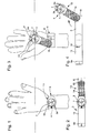
- FIGS. 1 to 4 a first embodiment is described below which corresponds to the basic principle of the invention, in which the housing 3 can occupy a normal position while being held on the wrist by a wraparound bracelet 5 closed by a clasp 8 (FIG 1) and a second position in which it is deployed outside the bracelet 5 to be positioned in the hand ( Figure 3).
- the clasp 8 will be illustrated later by a simple buckle 8a attached to the end of the strand 12 or bracelet 10 located at 12 o'clock. It is obvious that other types of clasps could be used.
- the casing 3 is fixedly mounted at the end of an additional flexible strand 10 made in only one part 14.
- the other end of the strand 14 has a pivot point 15 on the strand 6 of the bracelet 10 located at 6 o'clock.
- This pivot point 15 can be made by any known means, for example by means of a riveting game.
- the part 14, forming the additional strand 10, and thus also the housing 3, are held in the normal position (FIGS. 2) by means of locking / unlocking 19 between the strand 12 and the additional strand 10, as can be seen in Figure 4 showing the wristwatch unfolded flat.
- This locking / unlocking means 19 may be any known means, such as a pressure type device as shown, or a push-lock device.
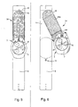
- Figures 5 and 6 show a top view, the wristwatch being unfolded flat, a second embodiment which differs from the previous in that the pivot point 15 of the additional strand 14 is positioned on the strand 12 of bracelet 5 to 12h.
- the housing 3 By deploying the housing 3, as shown in Figure 6, it is obvious that the display 7 will be reversed. It is then expected that the housing 3 is rotatably mounted on the end of the additional strand 14 around a point of rotation 9. It is then possible to return the housing 3 by 180 ° to have a normal reading of the display 7 when the housing 3 is positioned in the hand.
- the additional strand 14 may be flexible but not extensible in the direction of its length. According to a variant also shown in Figures 5 and 6, the additional strand 14 may also be extensible in the direction of its length so as to allow the user to have a better positioning in the palm of the hand, or at the level of fingers.
- the additional strand 14 is constituted by a sleeve 14a in which can slide a tongue 14b. Equivalently but not limited to, the strand 14 could be formed of spring links, or be made of an elastic material. This variant is obviously applicable to the first embodiment as well as other embodiments that will now be described.
- Figures 7 and 8 show a top view, the wristwatch being unfolded flat, a third embodiment which differs from the previous in that the additional flexible strand 10 is made in two parts 14, 16 which are articulated between them by a second pivot point 25.
- the first portion 14 has at its end the first pivot point 15 on the strap 5, said pivoting being effected for this embodiment on the strand 12 to 12h.
- the end of the second portion 16 supports the housing 3 fixedly mounted.
- the double pivoting of the housing 3 makes its display 7 is in the usual reading position when the housing 3 is deployed in the hand.
- the first part 14 is held on the wristband 5 as previously by a first locking / unlocking device 19 and the second part 16 by a second locking / unlocking device 29 provided between the end of the second part 16 and the first part 14.
- the first locking device / Unlocking 19 may advantageously be associated with the second pivoting device 25, so as to reduce the number of parts to be assembled.
- the variant provided in the second embodiment would, by designing one or other of the parts 14, 16 of the additional strand 10 expandably, to bring the pivot points 15, 25 of the center of the bracelet, if only for an aesthetic purpose.
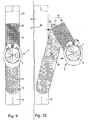
- Figures 9 and 10 corresponding to a fourth embodiment, having all the features of the previous mode, but differs in that the first portion 14 of the additional strand 10 is pivotally mounted on the strand 6 of strap 5 at 6 o'clock. As in the second embodiment, this assumes that the housing 3 can be reoriented by rotation about a point of rotation 9. This embodiment will therefore not be written further.
- FIGS. 11 and 12 show a fifth embodiment, on the same principle as the third and fourth embodiments, but which differs in that the junction between the parts 14, 16 of the additional strand 10 is achieved by means of A hinge 22.
- the first display 7 is facing the palm of the hand and is therefore not visible.
- this embodiment allows to provide a second display 17 in the bottom of the housing 3.
- it is a compass, but we can imagine any other type of display that can go from a simple vanity mirror to a calculator, phone, calendar, etc. keyboard. In the latter case it would obviously be necessary for the displays 7 and 17 to have inverted readings, or for rotation of the housing 3 to be provided, as in the second and fourth embodiments.
- the base pivot point 15 may be indifferently on one or other of the strands 6, 12 of the bracelet 5.
- FIGS. 13 and 14 show in perspective a sixth embodiment which differs from the previous embodiment in that the junction between the parts 14 and 16 of the additional strand 10 is further effected by means of a pivot axis 23 along the length of the second part 16, then formed of two disjoint elements 16a, 16b. Equivalently this pivoting 24 could be performed on the first portion 14 of the additional strand 10.
- This construction has the advantage of allowing to read indifferently one or other of the displays 7 or 17 when the housing is deployed in the hand.
- the flexible additional strand 10 is made in one or two parts 14, 16.
- FIGS. 15 and 16 show a seventh embodiment in which the additional strand 10 is made in more than two parts, namely in this example in three parts 14, 16, 18.
- the first part 14 comprises, as in the modes of Previous embodiment, a pivot point 15 on the bracelet 5.
- the second part 16 comprises, as in the fifth embodiment, a hinge 22 for connecting it to the first part 14.
- the third part 8 is connected to the second part 16 by a second hinge 24 and supports the housing 3.
- These three parts 14, 16, 18 can be held in place in the normal position by three locking / unlocking means of the type previously described, with a folding accordion which allows them to mask, or almost, under the housing 3.
- the double tilting around the hinges 22, 24 makes it possible to have the display 7 in position usual reading.
- the third part 18 may be merged with the housing 3, the hinge 24 then being formed by a bar 20 at the position 6 of the display 7.
- the bar 20 or, as shown for a better understanding of the portions 20a extending beyond the horns 3a of the housing 3 may also constitute locking / unlocking means snap-fastening in studs 21 integral with the strand 6 of the bracelet 5
- the same arrangement can be provided at 6 o'clock, so that the number of locking / unlocking means can be reduced to two.
- Figures 17 and 18 show somehow in condensed variants applicable to the previous embodiments. These figures show the possibility of snapping the housing 3 into a rigid housing 13 provided at the end of the additional strand 10 (in this case the part 16) for example by means of an S-spring 11 snapping into a slot 11a of said housing 13. This allows for example to be able to detach the chronograph from the bracelet and fix it to a link around the neck.
- the rigid housing 13 or the housing 3 can snap into another rigid housing 23 secured to the first part 14 when the additional strand 10 is in two parts, or directly to the strap 5 when the additional strand 10 is in one piece. only part.
- the rigid housing 23 can therefore be substituted for one of the locking / unlocking means
Landscapes
- Physics & Mathematics (AREA)
- General Physics & Mathematics (AREA)
- Electric Clocks (AREA)
- Professional, Industrial, Or Sporting Protective Garments (AREA)
- Physical Vapour Deposition (AREA)
Abstract
Description
- La présente invention concerne une montre-bracelet permettant d'afficher l'heure courante en position "normale" et éventuellement une deuxième information, horaire ou non horaire, dont la commande et la lecture sont facilitées en déployant le boîtier comportant les organes de commandes et d'affichage, sans nécessairement le désolidariser du bracelet maintenu au poignet par un fermoir.
- Dans ce qui suit, un affichage en "position normale" désigne un affichage dont le boîtier est fermement lié au bracelet maintenant la montre-bracelet au poignet et dont la lecture des informations affichées se fait du côté du dos de la main.
- Le boîtier peut occuper une position tout à fait usuelle en étant fixé à demeure au bracelet et donc présenter un affichage visible du côté du dos de la main, en étant sensiblement parallèle à Celui-ci. Le boîtier peut également légèrement s'écarter de cette position par basculement et/ou pivotement pour procurer une meilleure vision de l'affichage et/ou pour permettre l'accès à un deuxième affichage situé dans le fond du boîtier.
- Le brevet
US 1 804 048 décrit un dispositif dans lequel le boîtier bascule autour d'une charnière en pressant un bouton-poussoir traversant la carrure. Dans le brevetCH 161 610 - Dans le modèle "Tank basculante" de Cartier le boîtier est monté à pivotement dans un cadre, lui-même articulé par une charnière à un boîtier fixe, ce qui permet de retourner totalement le boîtier mobile et d'avoir accès à un deuxième affichage situé dans le fond du boîtier mobile lorsque celui-ci est ramené en position normale. Dans tous ces dispositifs de l'art antérieur le boîtier mobile conserve une forte liaison mécanique avec le bracelet, ne permettant une lecture de l'affichage que du côté du dos de la main.
- La présente invention apporte une solution nouvelle et innovante à la lecture d'une information portée par un affichage qui peut être complètement délocalisé de sa position normale, tout en conservant une liaison "de sécurité" avec le bracelet.
- A cet effet l'invention a pour objet une montre-bracelet à boîtier déployant comportant un bracelet réalisé en une seule pièce pour entourer totalement le poignet du porteur, en étant fermé par un fermoir reliant les deux brins de bracelet à 6h et à 12h. Le bracelet supporte indirectement un boîtier renfermant au moins un mouvement horloger pour l'affichage d'une information horaire et d'au moins une autre information horaire ou non horaire. L'invention est essentiellement caractérisée en ce que le boîtier est monté à l'extrémité d'un brin additionnel souple, dont l'autre extrémité est fixée à pivotement sur l'un des brins de bracelet. Par des moyens de verrouillage/déverrouillage entre le brin additionnel et le bracelet, le boîtier peut occuper une position normale et une deuxième position dans laquelle il peut être déployé pour être positionné dans la main, c'est-à-dire permettre la lecture de l'affichage et la manipulation des organes de commande dans une position opposée à la position dite normale.
- Le brin additionnel peut être réalisé en une partie ou en plusieurs parties, ce qui va déterminer la position u point de pivotement sur le bracelet pour que l'affichage soit orienté dans le bon sens lorsque le boîtier est monté fixe sur le brin additionnel et qu'il est tenu dans la main. Lorsque le brin additionnel est en une seule partie, le point de pivotement doit se trouver sur le brin à 6h; lorsqu'il est en deux parties, reliées entre elles pan un deuxième point de pivotement, il doit se trouver sur le brin à 12h.
- Si on choisit la deuxième alternative pour la position du point de pivotement, l'affichage va se trouver inversé, inconvénient qu'il est facile d'éliminer en prévoyant que le boîtier soit monté à rotation de façon à pouvoir être retourné de 180°.
- Lorsque le brin additionnel est en au moins deux parties, un point de pivotement, à l'exception de celui situé sur le bracelet, peut être remplacé par une charnière. Lorsque le nombre de parties constituant le brin additionnel est pair, un axe de pivotement selon la longueur dudit brin additionnel doit être prévu pour pouvoir retourner le boîtier lorsqu'il est déployé dans la main.
- D'autres avantages et caractéristiques de la présente invention apparaîtront dans la description suivante de divers modes de réalisation, donnés à titre illustratif et non limitatif, en référence aux dessins annexés dans lesquels:
- les figures 1 et 2 correspondent à un premier mode de réalisation d'une montre-bracelet selon l'invention, portée au poignet en position normale et en position développée à plat;
- la figure 3 et 4 correspondent à la même montre-bracelet que celle des figures 1 et 2 en position déployée dans la main, et en position développée à plat;
- les figures 5 à 12, correspondent à quatre autres modes de réalisation, en vue de dessus avec le bracelet développé à plat, respectivement en position normale pour les figures impaires, et position déployée pour les figures paires;
- les figures 13 et 14 représentent en perspective un sixième mode de réalisation, respectivement en position normale et en position déployée;
- les figures 15 et 16 représentent en vue de dessus avec le bracelet développé à plat, un septième mode de réalisation respectivement en position normale et en position déployée, et
- les figures 17 et 18 représentent en perspective des variantes des modes de réalisation précédents, respectivement en position normale et en position semi-déployée.
- Les modes de réalisation qui suivent sont plus particulièrement illustrés par une montre-bracetet à affichage analogique dont le boîtier 3 contient un mouvement permettant d'une part d'afficher l'heure courante sur un affichage 7, d'autre part d'entraîner un mécanisme de chronographe commandé par des boutons poussoir 2a, 2b, disposés de part et d'autre d'une couronne 4, pour afficher l'information de chronométrage sur le même affichage 7 que l'heure courante.
- Il est bien évident, sans sortie du cadre de l'invention que l'affichage 7 pourrait être de type analogique à cristaux liquides.
- En se référant d'abord aux figures 1 à 4, on décrit ci-après un premier mode de réalisation qui correspond au principe de base de l'invention, dans lequel le boîtier 3 peut occuper une position normale en étant maintenu au poignet par un bracelet enveloppant 5 fermé par un fermoir 8 (fig. 1) et une deuxième position dans laquelle il est déployé en dehors du bracelet 5 pour pouvoir être positionné dans la main (fig. 3). Le fermoir 8 sera illustré par la suite par une simple boucle à ardillon 8a fixée à l'extrémité du brin 12 ou bracelet 10 situé à 12h. Il est bien évident que d'autre types de fermoirs pourraient être utilisés.
- Comme on le voit plus facilement sur la figure 2, lorsque le fermoir 8 est ouvert et que la montre-bracelet est posée à plat sur une table, le boîtier 3 est monté fixe à l'extrémité d'un brin additionnel 10 souple réalisé en une seule partie 14. L'autre extrémité du brin 14 comporte un point de pivotement 15 sur le brin 6 du bracelet 10 situé à 6h. Ce point de pivotement 15 peut être réalisé par tout moyen connu, par exemple au moyen d'un rivetage à jeu. La partie 14, formant le brin additionnel 10, et donc également le boîtier 3, sont maintenus en position normale (figures 1 et 2) par des moyens de verrouillage/deverrouillage 19 entre le brin 12 et le brin additionnel 10, comme on peut le voir sur a figure 4 représentant la montre-bracelet dépliée à plat. Ce moyen de verrouillage/déverrouillage 19 peut-être un moyen quelconque connu, tel qu'un dispositif de type pression comme représenté, ou un dispositif à verrou-poussoir.
- Les figures 5 et 6 représentent en vue dessus, la montre-bracelet étant dépliée à plat, un deuxième mode de réalisation qui diffère du précédent en ce que le point de pivotement 15 du brin additionnel 14 est positionné sur le brin 12 de bracelet 5 à 12h. En déployant le boîtier 3, comme représenté à la figure 6, il est bien évident que l'affichage 7 va se trouver renversé. Il est alors prévu que le boîtier 3 soit monté à rotation sur l'extrémité du brin additionnel 14 autour d'un point de rotation 9. Il est alors possible de retourner le boîtier 3 de 180° pour avoir une lecture normale de l'affichage 7 lorsque le boîtier 3 est positionné dans la main.
- Comme dans le premier mode de réalisation, le brin additionnel 14 peut être souple mais non extensible dans le sens de sa longueur. Selon une variante également représentée aux figures 5 et 6, le brin additionnel 14 peut aussi être extensible dans le sens de sa longueur de façon à permettre à l'usager d'avoir un meilleur positionnement dans le creux de la main, voire au niveau des doigts. Dans l'exemple représenté, le brin additionnel 14 est constitué par un fourreau 14a dans lequel peut coulisser une languette 14b. De façon équivalente mais non limitative, le brin 14 pourrait être formé de maillons à ressorts, ou être réalisé en un matériau élastique. Cette variante est bien évidemment applicable au premier mode de réalisation ainsi qu'aux autres modes de réalisation qui vont maintenant être décrits.
- Les figures 7 et 8 représentent en vue de dessus, la montre-bracelet étant dépliée à plat, un troisième mode de réalisation qui diffère des précédents en ce que le brin additionnel souple 10 est réalisé en deux parties 14, 16 qui sont articulées entre elles par un deuxième point de pivotement 25. La première partie 14 comporte à son extrémité le premier point de pivotement 15 sur le bracelet 5, ledit pivotement s'effectuant pour ce mode de réalisation sur le brin 12 à 12h.
- L'extrémité de la deuxième partie 16 supporte le boîtier 3 monté de façon fixe. Le double pivotement du boîtier 3 fait que son affichage 7 se trouve en position habituelle de lecture lorsque le boîtier 3 est déployé dans la main. Lorsque le boîtier 3 est en position normale (figure 7) la première partie 14 est maintenue sur le bracelet 5 comme précédemment par un premier dispositif de verrouillage/déverrouillage 19 et la deuxième partie 16 par un deuxième dispositif de verrouillage/déverrouillage 29 prévu entre l'extrémité de la deuxième partie 16 et la première partie 14. On observera que le premier dispositif de verrouillage/déverrouillage 19 peut avantageusement être associé au deuxième dispositif de pivotement 25, de façon à réduire le nombre de pièces à assembler.
- De même, la variante prévue dans le deuxième mode de réalisation permettrait, en concevant l'une ou l'autre des parties 14, 16 du brin additionnel 10 de façon extensible, de rapprocher les points de pivotement 15, 25 du centre du bracelet, ne serait-ce que dans un but esthétique.
- Les figures 9 et 10 correspondant à un quatrième mode de réalisation, ayant toutes les caractéristiques du mode précédent, mais qui en diffère en ce que la première partie 14 du brin additionnel 10 est monté à pivotement sur le brin 6 de bracelet 5 à 6h. Comme dans le deuxième mode de réalisation, cela suppose que le boîtier 3 puisse être réorienté par rotation autour d'un point de rotation 9. Ce mode de réalisation ne sera donc pas écrit plus avant.
- Les figures 11 et 12 montrent un cinquième mode de réalisation, sur le même principe que les troisième et quatrième modes de réalisation, mais qui en diffère en ce que la jonction entre les parties 14, 16 du brin additionnel 10 est réalisée au moyen d'une charnière 22. Dans ces conditions après déploiement du boîtier 3 le premier affichage 7 se trouve en regard du creux de la main et n'est donc pas visible. Par contre ce mode de réalisation permet de prévoir un deuxième affichage 17 dans le fond du boîtier 3. Dans l'exemple représenté il s'agit d'une boussole, mais on peut imaginer tout autre type d'affichage pouvant aller d'un simple miroir de courtoisie à un clavier de calculatrice, de téléphone, d'agenda, etc. Dans ce dernier cas il conviendrait évidemment que les affichages 7 et 17 présentent des lectures inversées, ou qu'il soit prévu une rotation du boîtier 3, comme dans les deuxième et quatrième mode de réalisation. On observera que le point de pivotement de base 15 peut se trouver indifféremment sur l'un ou l'autre des brins 6, 12 du bracelet 5.
- Les figures 13 et 14, montre en perspective un sixième mode de réalisation qui diffère du précédent en ce que la jonction entre les parties 14 et 16 du brin additionnel 10 s'effectue en outre au moyen d'un axe de pivotement 23 selon la longueur de la deuxième partie 16, alors formée de deux éléments disjoints 16a, 16b. De façon équivalente ce pivotement 24 pourrait s'effectuer sur la première partie 14 du brin additionnel 10. Cette construction a l'avantage de permettre de lire indifféremment l'un ou l'autre des affichages 7 ou 17 lorsque le boîtier est déployé dans la main.
- Dans les modes de réalisation qui viennent d'être décrits, le brin additionnel souple 10 est réalisé en une ou deux parties 14,16. Les figures 15 et 16 représentent un septième de mode réalisation dans lequel le brin additionnel 10 est réalisé en plus de deux parties, à savoir dans cet exemple en trois parties 14, 16, 18. La première partie 14 comporte, comme dans les modes de réalisation précédents, un point de pivotement 15 sur le bracelet 5. La deuxième partie 16 comporte, comme dans le cinquième mode de réalisation une charnière 22 permettant de la relier à la première partie 14. La troisième partie 8 est reliée à la deuxième partie 16 par une deuxième charnière 24 et supporte le boîtier 3. Ces trois parties 14, 16, 18 peuvent être maintenues en place en position normale par trois moyens de verrouillage/déverrouillage du type de ceux précédemment décrits, avec un pliage en accordéon qui permet de les masquer, ou presque, sous le boîtier 3. Lorsqu'on veut placer le boîtier 3 dans la main, le double basculement autour des charnières 22, 24 permet d'avoir l'affichage 7 en position de lecture habituelle.
- On observera également, selon la variante représentée, que la troisième partie 18 peut être confondue avec le boîtier 3, la charnière 24 étant alors formé par une barrette 20 à la position 6 de l'affichage 7.
- En outre, la barrette 20 ou, comme représenté pour un meilleure compréhension des portions 20a s'étendant au delà des cornes 3a du boîtier 3 peuvent également constituer les moyens de verrouillage/déverrouillage par encliquetage dans des plots 21 solidaires du brin 6 du bracelet 5. Un même agencement peut être prévu à 6h, de sorte que le nombre de moyen de verrouillage/déverrouillage peut être ramené à deux.
- Les figures 17 et 18 représentent, en quelque sorte en condensé, des variantes applicables aux modes de réalisation précédents. Ces figures montrent la possibilité d'encliqueter le boîtier 3 dans un logement rigide 13 prévu à l'extrémité du brin additionnel 10 (dans ce cas la partie 16) par exemple au moyen d'un ressort 11 à en S venant s'encliqueter dans une fente 11 a dudit logement 13. Cela permet par exemple de pouvoir détacher le chronographe du bracelet et le fixer à un lien passé autour du cou.
- De même le logement rigide 13 ou le boîtier 3 peuvent venir s'encliqueter dans un autre logement rigide 23 assujetti à la première partie 14 lorsque le brin additionnel 10 est en deux parties, ou directement au bracelet 5 lorsque le brin additionnel 10 est en une seule partie. Le logement rigide 23 peut donc se substituer à l'un des moyens de verrouillage/déverrouillage
- Bien évidemment ces variantes peuvent être combinées ou mises en oeuvre séparément, quels que soient les modes de réalisation, et d'autres modes de réalisation peuvent être envisagés par l'homme de métier sans sortir du cadre de la présente invention.
Claims (17)
- Montre-bracelet, à boîtier (3) déployant comportant un bracelet (5) en une seule pièce fixé autour du poignet de l'usager par un fermoir (8) reliant les brins (6, 12) à 6h et à 12h, le boîtier (3) supportant au moins un mouvement horloger et au moins un affichage (7, 17) pour l'heure courante et pour l'accès à d'autres informations horaires ou non horaires, caractérisée en ce qu'elle comporte un brin additionnel souple (10), en ou en plusieurs parties (14,16,18), dont une extrémité présente un point de pivotement (15) sur l'un des brins (6, 12) du bracelet (5), ledit pivotement s'effectuant autour d'un axe perpendiculaire au plan des brins (6, 12), et dont l'autre extrémité supporte le boîtier (3), soit pour le maintenir en position normale sur le bracelet par des moyens de verrouillage/déverrouillage (19, 29), soit pour permettre son déploiement dans la main, en agissant sur les moyens de déverrouillage (19, 29).
- Montre-bracelet selon la revendication 1, caractérisée en ce que le brin additionnel (10) est en une seule partie (14) et comporte son point de pivotement (15) sur le brin (6) du bracelet (5) situé à 6h, le boîtier (3) étant monté fixe sur l'autre extrémité de la partie (14) du brin additionnel (10).
- Montre-bracelet selon la revendication 1 ,caractérisée en ce que le brin additionnel (10) est en une seule partie (14) et comporte son point de pivotement (15) sur le brin (12) du bracelet (5) situé à 12h, le boîtier (5) étant monté à rotation sur l'autre extrémité du la partie 14 du brin additionnel (10), de façon à pouvoir pivoter de 180°.
- Montre-bracelet selon la revendication 1, caractérisée en ce que le brin additionnel souple (10) est réalisé en deux parties (14,16) reliées entre elles par un deuxième point de pivotement (25) autour d'un axe perpendiculaire au plan des parties (14, 16) du brin additionnel (10), la première partie (14) comportant à son extrémité le point de pivotement (15) sur le bracelet (5), et à l'autre extrémité un premier moyen de verrouiitage/déverrouillage 19, et la deuxième partie (16) supportant le boîtier (3) à son extrémité et un deuxième moyen de verrouillage/déverrouillage (29).
- Montre-bracelet selon la revendication 4, caractérisée en ce que le point de pivotement (15) sur le bracelet (5) est situé sur le brin (12) à 12h, le boîtier (3) étant monté fixe sur l'extrémité de la deuxième partie (16) du brin additionnel (10).
- Montre-bracelet selon la revendication 4, caractérisée en ce que le point de pivotement (15) sur le bracelet (5) est situé sur le brin (6) à 6h, le boîtier (3) étant monté à rotation sur l'extrémité de la deuxième partie (16) du brin additionnel (10).
- Montre-bracelet selon la revendication 1, caractérisée en ce que le brin additionnel souple (10) est réalisé en deux parties (14, 16) reliées entre elles par une charnière (22), la premier partie (14) comportant à son extrémité le point de pivotement (15) sur le bracelet (5) et la deuxième partie (14) supportant à son extrémité un boîtier fixe (3) ayant un premier affichage (7) d'au moins l'heure courante en position normale, et sur sa face opposée un deuxième affichage (17) d'une autre information horaire ou non horaire.
- Montre-bracelet selon la revendication 7, caractérisée en ce que la jonction entre les deux partie (14,16) du brin additionnel (10) comporte en outre un axe de pivotement (23) selon a longueur dudit brin additionnel (10).
- Montre-bracelet selon les revendication 7 ou 8, caractérisée en ce que le boîtier (3, 13) est en outre monté à rotation sur la partie terminale (16) du brin additionnel (10).
- Montre-bracelet selon la revendication 1, caractérisée en ce que le brin additionnel souple 10 est réalisé en trois parties (14,16,18), la première partie (14) comportant à son extrémité le point de pivotement (15) sur le bracelet (5), la deuxième partie (16) étant reliée à la première partie (14) par une charnière (22) et la troisième partie (18) étant reliée à la deuxième partie (16) par une deuxième charnière (24) en supportant un boîtier fixe (3).
- Montre-bracelet selon la revendication 10, caractérisée en ce que le boîtier (3) comporte des barrettes (20), l'une d'elles étant confondue avec la deuxième charnière (24) et constituant un premier moyen de verrouillage/déverrouillage par encliquetage dans des plots (21) solidaires du bracelet (5), l'autre barrette constituant le deuxième moyen de verrouillage/déverrouillage par encliquetage dans d'autres plots (21) également solidaires du bracelet (5).
- Montre-bracelet selon la revendication 1, caractérisée en ce que au moins une des parties (14,16,18) du brin additionnel souple (10), est également extensible dans le sens de la longueur.
- Montre-bracelet selon la revendication 1, caractérisée en ce que le boîtier (3) est assujetti à un logement (13) lui-même solidarisé au brin additionnel (10).
- Montre-bracelet, selon la revendication 13, caractérisée en ce que le boîtier (3) est séparable de son logement (13).
- Montre-bracelet selon une quelconque des revendications 1 à 14, caractérisée en ce que le boîtier (3) comporte des organes de commande extérieurs (2a, 2b) pour une fonction chronographe.
- Montre-bracelet selon la revendication 15, caractérisée en ce que les organes de commande (2a, 2b) sont positionnés à 12h.
- Montre-bracelet selon une quelconque des revendications 1 à 14, caractérisée en ce que le second affichage correspond à une fonction téléphone.
Priority Applications (9)
| Application Number | Priority Date | Filing Date | Title |
|---|---|---|---|
| AT06018664T ATE426841T1 (de) | 2006-09-06 | 2006-09-06 | Armbanduhr mit ausschwenkbarem gehause |
| EP06018664A EP1898278B1 (fr) | 2006-09-06 | 2006-09-06 | Montre-bracelet à boitier déployant |
| DE602006005929T DE602006005929D1 (de) | 2006-09-06 | 2006-09-06 | Armbanduhr mit ausschwenkbarem Gehäuse |
| SG200706419-9A SG140583A1 (en) | 2006-09-06 | 2007-08-31 | Wristwatch with an unfolding case |
| JP2007228656A JP5090110B2 (ja) | 2006-09-06 | 2007-09-04 | 広げることが可能なケースを有する時計 |
| KR1020070089770A KR20080022514A (ko) | 2006-09-06 | 2007-09-05 | 펼쳐진 케이스를 포함하는 시계 |
| CN2007101497365A CN101140448B (zh) | 2006-09-06 | 2007-09-05 | 具有展开表壳的手表 |
| US11/851,213 US7794139B2 (en) | 2006-09-06 | 2007-09-06 | Wristwatch with an unfolding case |
| HK08109908.4A HK1119465B (en) | 2006-09-06 | 2008-09-05 | Wristwatch with an unfolding case |
Applications Claiming Priority (1)
| Application Number | Priority Date | Filing Date | Title |
|---|---|---|---|
| EP06018664A EP1898278B1 (fr) | 2006-09-06 | 2006-09-06 | Montre-bracelet à boitier déployant |
Publications (2)
| Publication Number | Publication Date |
|---|---|
| EP1898278A1 true EP1898278A1 (fr) | 2008-03-12 |
| EP1898278B1 EP1898278B1 (fr) | 2009-03-25 |
Family
ID=38085978
Family Applications (1)
| Application Number | Title | Priority Date | Filing Date |
|---|---|---|---|
| EP06018664A Not-in-force EP1898278B1 (fr) | 2006-09-06 | 2006-09-06 | Montre-bracelet à boitier déployant |
Country Status (8)
| Country | Link |
|---|---|
| US (1) | US7794139B2 (fr) |
| EP (1) | EP1898278B1 (fr) |
| JP (1) | JP5090110B2 (fr) |
| KR (1) | KR20080022514A (fr) |
| CN (1) | CN101140448B (fr) |
| AT (1) | ATE426841T1 (fr) |
| DE (1) | DE602006005929D1 (fr) |
| SG (1) | SG140583A1 (fr) |
Cited By (1)
| Publication number | Priority date | Publication date | Assignee | Title |
|---|---|---|---|---|
| EP3058840A1 (fr) * | 2015-02-20 | 2016-08-24 | Swatch Ag | Montre à bracelet extensible |
Families Citing this family (4)
| Publication number | Priority date | Publication date | Assignee | Title |
|---|---|---|---|---|
| US8784218B2 (en) * | 2011-11-15 | 2014-07-22 | Armaband, Llc | Self defense hand band |
| JP3182688U (ja) * | 2013-01-25 | 2013-04-04 | 有限会社イナバゴム機工 | 多用途脱着バンド |
| KR20170069766A (ko) | 2015-12-11 | 2017-06-21 | 삼성전자주식회사 | 중심에 구멍을 갖는 인쇄 회로 기판을 포함하는 스마트 워치 |
| US9946227B2 (en) | 2016-06-17 | 2018-04-17 | Wissam J. Aoun | Reflective devices, methods and uses therefor |
Citations (3)
| Publication number | Priority date | Publication date | Assignee | Title |
|---|---|---|---|---|
| CH320858A (fr) * | 1955-06-06 | 1957-04-15 | Georges Ducommun Fils De | Bracelet |
| DE29613950U1 (de) * | 1996-08-12 | 1996-12-19 | Bryan, Thomas, 80803 München | Uhr für In-Line-Skater, Radfahrer, Skifahrer angebracht am Handschuh oder Handschutz |
| DE20212658U1 (de) * | 2001-08-22 | 2002-11-14 | Bonnet, Klaus, Dipl.-Ing., 64287 Darmstadt | Armbanduhr |
Family Cites Families (17)
| Publication number | Priority date | Publication date | Assignee | Title |
|---|---|---|---|---|
| US601982A (en) * | 1898-04-05 | Watchcase | ||
| US1804048A (en) * | 1929-04-13 | 1931-05-05 | Bosch Fritz | Timepiece serving as alpha watch or traveling clock |
| CH161610A (fr) | 1932-05-30 | 1933-05-15 | Buetzer Henri | Montre. |
| US2926825A (en) * | 1957-01-31 | 1960-03-01 | Russell T Wing | Watch supporting devices |
| GB8416511D0 (en) * | 1984-06-28 | 1984-08-01 | Lloyd B | Stop watch |
| JPH0724236Y2 (ja) * | 1990-01-11 | 1995-06-05 | 廣 小林 | 三方断截機の刃物安全装置 |
| JPH03106284U (fr) * | 1990-02-19 | 1991-11-01 | ||
| JPH05232253A (ja) * | 1992-02-24 | 1993-09-07 | Hiroo Yasui | そで口腕時計 |
| US5239521A (en) * | 1992-05-29 | 1993-08-24 | At&T Bell Laboratories | Wrist telephone |
| US5499292A (en) * | 1994-05-06 | 1996-03-12 | At&T Corp. | On hook/off hook mechanism for wrist telephone |
| US5659611A (en) * | 1996-05-17 | 1997-08-19 | Lucent Technologies Inc. | Wrist telephone |
| US5779113A (en) * | 1996-12-02 | 1998-07-14 | Huang; Chen-Chung | Watch holder system |
| US6519207B1 (en) * | 1998-10-05 | 2003-02-11 | Jason B. Lukacsko | Outdoor glove watch |
| USD438483S1 (en) * | 1999-04-23 | 2001-03-06 | Zuri Mesica | Handlette |
| US6991364B2 (en) * | 2001-07-31 | 2006-01-31 | The Timberland Company | Same-hand control of a multi-function device |
| CN2554667Y (zh) * | 2002-07-31 | 2003-06-04 | 宋志利 | 手背佩戴式手表/计时器 |
| CN1487712A (zh) * | 2002-08-10 | 2004-04-07 | 王新云 | 一种手表式手机的翻盖装置 |
-
2006
- 2006-09-06 AT AT06018664T patent/ATE426841T1/de not_active IP Right Cessation
- 2006-09-06 EP EP06018664A patent/EP1898278B1/fr not_active Not-in-force
- 2006-09-06 DE DE602006005929T patent/DE602006005929D1/de active Active
-
2007
- 2007-08-31 SG SG200706419-9A patent/SG140583A1/en unknown
- 2007-09-04 JP JP2007228656A patent/JP5090110B2/ja not_active Expired - Fee Related
- 2007-09-05 KR KR1020070089770A patent/KR20080022514A/ko not_active Ceased
- 2007-09-05 CN CN2007101497365A patent/CN101140448B/zh not_active Expired - Fee Related
- 2007-09-06 US US11/851,213 patent/US7794139B2/en not_active Expired - Fee Related
Patent Citations (3)
| Publication number | Priority date | Publication date | Assignee | Title |
|---|---|---|---|---|
| CH320858A (fr) * | 1955-06-06 | 1957-04-15 | Georges Ducommun Fils De | Bracelet |
| DE29613950U1 (de) * | 1996-08-12 | 1996-12-19 | Bryan, Thomas, 80803 München | Uhr für In-Line-Skater, Radfahrer, Skifahrer angebracht am Handschuh oder Handschutz |
| DE20212658U1 (de) * | 2001-08-22 | 2002-11-14 | Bonnet, Klaus, Dipl.-Ing., 64287 Darmstadt | Armbanduhr |
Cited By (3)
| Publication number | Priority date | Publication date | Assignee | Title |
|---|---|---|---|---|
| EP3058840A1 (fr) * | 2015-02-20 | 2016-08-24 | Swatch Ag | Montre à bracelet extensible |
| WO2016131508A1 (fr) * | 2015-02-20 | 2016-08-25 | Swatch Ag | Montre a bracelet extensible |
| US9867435B2 (en) | 2015-02-20 | 2018-01-16 | Swatch Ag | Watch with extending watchband |
Also Published As
| Publication number | Publication date |
|---|---|
| CN101140448B (zh) | 2011-02-02 |
| KR20080022514A (ko) | 2008-03-11 |
| ATE426841T1 (de) | 2009-04-15 |
| EP1898278B1 (fr) | 2009-03-25 |
| DE602006005929D1 (de) | 2009-05-07 |
| CN101140448A (zh) | 2008-03-12 |
| SG140583A1 (en) | 2008-03-28 |
| JP5090110B2 (ja) | 2012-12-05 |
| JP2008064756A (ja) | 2008-03-21 |
| US20080062822A1 (en) | 2008-03-13 |
| HK1119465A1 (en) | 2009-03-06 |
| US7794139B2 (en) | 2010-09-14 |
Similar Documents
| Publication | Publication Date | Title |
|---|---|---|
| EP1116075B1 (fr) | Montre-bracelet reversible | |
| EP2322997B1 (fr) | Objet portable ayant un bracelet interchangeable | |
| EP1795979B1 (fr) | Pièce d'horlogerie à boîtier basculant | |
| EP0294320A1 (fr) | Assemblage comportant un boîtier fixé sur un support | |
| FR2661012A1 (fr) | Montre a cadran transparent a decor amovible. | |
| FR2511519A1 (fr) | Dispositif d'horlogerie comportant un element multifonctionnel | |
| EP1898278B1 (fr) | Montre-bracelet à boitier déployant | |
| EP3709103B1 (fr) | Dispositif de blocage de lunette tournante | |
| EP1437635B1 (fr) | Boîte de montre | |
| WO2005043259A1 (fr) | Piece d'horlogerie a boite de montre reversible | |
| EP3287856A1 (fr) | Ensemble prévu pour porter une superstructure de boîte de montre de manière à former avec celle-ci une boîte de montre-bracelet étagée destinée notamment à être portée avec une chemise à manches longues | |
| EP2120625B1 (fr) | Bracelet pour montre | |
| EP4154752B1 (fr) | Maillon confort extensible | |
| EP3569090B1 (fr) | Systeme d`attache d'un bracelet a une boite de montre | |
| FR2776785A1 (fr) | Ensemble constitutif de l'habillement d'une montre | |
| CH697850B1 (fr) | Appareil portable avec couvercle ouvrant/fermant et structure de carrure pour mouvement d'horlogerie. | |
| CH693294A5 (fr) | Montre-bracelet réversible. | |
| EP1269879B1 (fr) | Dispositif de fixation des brins de bracelet à une boîte | |
| FR2670995A1 (fr) | Bracelet pour montre. | |
| CH702308A2 (fr) | Objet portable ayant un bracelet interchangeable. | |
| EP1810089B1 (fr) | Boite de montre | |
| WO1982004335A1 (fr) | Montre munie d'un organe de liaison | |
| EP1513031B1 (fr) | Pièce d'horlogerie comprenant deux boîtes susceptibles de pivoter l'une par rapport à l'autre | |
| EP0092510B1 (fr) | Boîtier de montre | |
| CH714263B1 (fr) | Boîtier montre-bracelet. |
Legal Events
| Date | Code | Title | Description |
|---|---|---|---|
| PUAI | Public reference made under article 153(3) epc to a published international application that has entered the european phase |
Free format text: ORIGINAL CODE: 0009012 |
|
| 17P | Request for examination filed |
Effective date: 20070703 |
|
| AK | Designated contracting states |
Kind code of ref document: A1 Designated state(s): AT BE BG CH CY CZ DE DK EE ES FI FR GB GR HU IE IS IT LI LT LU LV MC NL PL PT RO SE SI SK TR |
|
| AX | Request for extension of the european patent |
Extension state: AL BA HR MK YU |
|
| AKX | Designation fees paid |
Designated state(s): AT BE BG CH CY CZ DE DK EE ES FI FR GB GR HU IE IS IT LI LT LU LV MC NL PL PT RO SE SI SK TR |
|
| GRAP | Despatch of communication of intention to grant a patent |
Free format text: ORIGINAL CODE: EPIDOSNIGR1 |
|
| GRAS | Grant fee paid |
Free format text: ORIGINAL CODE: EPIDOSNIGR3 |
|
| RAP1 | Party data changed (applicant data changed or rights of an application transferred) |
Owner name: THE SWATCH GROUP MANAGEMENT SERVICES AG |
|
| GRAA | (expected) grant |
Free format text: ORIGINAL CODE: 0009210 |
|
| AK | Designated contracting states |
Kind code of ref document: B1 Designated state(s): AT BE BG CH CY CZ DE DK EE ES FI FR GB GR HU IE IS IT LI LT LU LV MC NL PL PT RO SE SI SK TR |
|
| REG | Reference to a national code |
Ref country code: GB Ref legal event code: FG4D Free format text: NOT ENGLISH |
|
| REG | Reference to a national code |
Ref country code: CH Ref legal event code: EP |
|
| REG | Reference to a national code |
Ref country code: IE Ref legal event code: FG4D Free format text: LANGUAGE OF EP DOCUMENT: FRENCH |
|
| REF | Corresponds to: |
Ref document number: 602006005929 Country of ref document: DE Date of ref document: 20090507 Kind code of ref document: P |
|
| REG | Reference to a national code |
Ref country code: CH Ref legal event code: NV Representative=s name: ICB INGENIEURS CONSEILS EN BREVETS SA |
|
| PG25 | Lapsed in a contracting state [announced via postgrant information from national office to epo] |
Ref country code: SI Free format text: LAPSE BECAUSE OF FAILURE TO SUBMIT A TRANSLATION OF THE DESCRIPTION OR TO PAY THE FEE WITHIN THE PRESCRIBED TIME-LIMIT Effective date: 20090325 Ref country code: LT Free format text: LAPSE BECAUSE OF FAILURE TO SUBMIT A TRANSLATION OF THE DESCRIPTION OR TO PAY THE FEE WITHIN THE PRESCRIBED TIME-LIMIT Effective date: 20090325 Ref country code: FI Free format text: LAPSE BECAUSE OF FAILURE TO SUBMIT A TRANSLATION OF THE DESCRIPTION OR TO PAY THE FEE WITHIN THE PRESCRIBED TIME-LIMIT Effective date: 20090325 |
|
| PG25 | Lapsed in a contracting state [announced via postgrant information from national office to epo] |
Ref country code: AT Free format text: LAPSE BECAUSE OF FAILURE TO SUBMIT A TRANSLATION OF THE DESCRIPTION OR TO PAY THE FEE WITHIN THE PRESCRIBED TIME-LIMIT Effective date: 20090325 Ref country code: SE Free format text: LAPSE BECAUSE OF FAILURE TO SUBMIT A TRANSLATION OF THE DESCRIPTION OR TO PAY THE FEE WITHIN THE PRESCRIBED TIME-LIMIT Effective date: 20090625 Ref country code: LV Free format text: LAPSE BECAUSE OF FAILURE TO SUBMIT A TRANSLATION OF THE DESCRIPTION OR TO PAY THE FEE WITHIN THE PRESCRIBED TIME-LIMIT Effective date: 20090325 Ref country code: PL Free format text: LAPSE BECAUSE OF FAILURE TO SUBMIT A TRANSLATION OF THE DESCRIPTION OR TO PAY THE FEE WITHIN THE PRESCRIBED TIME-LIMIT Effective date: 20090325 |
|
| NLV1 | Nl: lapsed or annulled due to failure to fulfill the requirements of art. 29p and 29m of the patents act | ||
| REG | Reference to a national code |
Ref country code: IE Ref legal event code: FD4D |
|
| PG25 | Lapsed in a contracting state [announced via postgrant information from national office to epo] |
Ref country code: PT Free format text: LAPSE BECAUSE OF FAILURE TO SUBMIT A TRANSLATION OF THE DESCRIPTION OR TO PAY THE FEE WITHIN THE PRESCRIBED TIME-LIMIT Effective date: 20090831 Ref country code: ES Free format text: LAPSE BECAUSE OF FAILURE TO SUBMIT A TRANSLATION OF THE DESCRIPTION OR TO PAY THE FEE WITHIN THE PRESCRIBED TIME-LIMIT Effective date: 20090706 Ref country code: EE Free format text: LAPSE BECAUSE OF FAILURE TO SUBMIT A TRANSLATION OF THE DESCRIPTION OR TO PAY THE FEE WITHIN THE PRESCRIBED TIME-LIMIT Effective date: 20090325 Ref country code: CZ Free format text: LAPSE BECAUSE OF FAILURE TO SUBMIT A TRANSLATION OF THE DESCRIPTION OR TO PAY THE FEE WITHIN THE PRESCRIBED TIME-LIMIT Effective date: 20090325 |
|
| PG25 | Lapsed in a contracting state [announced via postgrant information from national office to epo] |
Ref country code: RO Free format text: LAPSE BECAUSE OF FAILURE TO SUBMIT A TRANSLATION OF THE DESCRIPTION OR TO PAY THE FEE WITHIN THE PRESCRIBED TIME-LIMIT Effective date: 20090325 Ref country code: NL Free format text: LAPSE BECAUSE OF FAILURE TO SUBMIT A TRANSLATION OF THE DESCRIPTION OR TO PAY THE FEE WITHIN THE PRESCRIBED TIME-LIMIT Effective date: 20090325 Ref country code: SK Free format text: LAPSE BECAUSE OF FAILURE TO SUBMIT A TRANSLATION OF THE DESCRIPTION OR TO PAY THE FEE WITHIN THE PRESCRIBED TIME-LIMIT Effective date: 20090325 Ref country code: IS Free format text: LAPSE BECAUSE OF FAILURE TO SUBMIT A TRANSLATION OF THE DESCRIPTION OR TO PAY THE FEE WITHIN THE PRESCRIBED TIME-LIMIT Effective date: 20090725 |
|
| PG25 | Lapsed in a contracting state [announced via postgrant information from national office to epo] |
Ref country code: IE Free format text: LAPSE BECAUSE OF FAILURE TO SUBMIT A TRANSLATION OF THE DESCRIPTION OR TO PAY THE FEE WITHIN THE PRESCRIBED TIME-LIMIT Effective date: 20090325 Ref country code: DK Free format text: LAPSE BECAUSE OF FAILURE TO SUBMIT A TRANSLATION OF THE DESCRIPTION OR TO PAY THE FEE WITHIN THE PRESCRIBED TIME-LIMIT Effective date: 20090325 Ref country code: BG Free format text: LAPSE BECAUSE OF FAILURE TO SUBMIT A TRANSLATION OF THE DESCRIPTION OR TO PAY THE FEE WITHIN THE PRESCRIBED TIME-LIMIT Effective date: 20090625 |
|
| PLBE | No opposition filed within time limit |
Free format text: ORIGINAL CODE: 0009261 |
|
| STAA | Information on the status of an ep patent application or granted ep patent |
Free format text: STATUS: NO OPPOSITION FILED WITHIN TIME LIMIT |
|
| 26N | No opposition filed |
Effective date: 20091229 |
|
| BERE | Be: lapsed |
Owner name: THE SWATCH GROUP MANAGEMENT SERVICES AG Effective date: 20090930 |
|
| PG25 | Lapsed in a contracting state [announced via postgrant information from national office to epo] |
Ref country code: MC Free format text: LAPSE BECAUSE OF NON-PAYMENT OF DUE FEES Effective date: 20090930 |
|
| PG25 | Lapsed in a contracting state [announced via postgrant information from national office to epo] |
Ref country code: BE Free format text: LAPSE BECAUSE OF NON-PAYMENT OF DUE FEES Effective date: 20090930 |
|
| PG25 | Lapsed in a contracting state [announced via postgrant information from national office to epo] |
Ref country code: GR Free format text: LAPSE BECAUSE OF FAILURE TO SUBMIT A TRANSLATION OF THE DESCRIPTION OR TO PAY THE FEE WITHIN THE PRESCRIBED TIME-LIMIT Effective date: 20090626 |
|
| PG25 | Lapsed in a contracting state [announced via postgrant information from national office to epo] |
Ref country code: LU Free format text: LAPSE BECAUSE OF NON-PAYMENT OF DUE FEES Effective date: 20090906 |
|
| PG25 | Lapsed in a contracting state [announced via postgrant information from national office to epo] |
Ref country code: HU Free format text: LAPSE BECAUSE OF FAILURE TO SUBMIT A TRANSLATION OF THE DESCRIPTION OR TO PAY THE FEE WITHIN THE PRESCRIBED TIME-LIMIT Effective date: 20090926 |
|
| PG25 | Lapsed in a contracting state [announced via postgrant information from national office to epo] |
Ref country code: TR Free format text: LAPSE BECAUSE OF FAILURE TO SUBMIT A TRANSLATION OF THE DESCRIPTION OR TO PAY THE FEE WITHIN THE PRESCRIBED TIME-LIMIT Effective date: 20090325 |
|
| PG25 | Lapsed in a contracting state [announced via postgrant information from national office to epo] |
Ref country code: CY Free format text: LAPSE BECAUSE OF FAILURE TO SUBMIT A TRANSLATION OF THE DESCRIPTION OR TO PAY THE FEE WITHIN THE PRESCRIBED TIME-LIMIT Effective date: 20090325 |
|
| PGFP | Annual fee paid to national office [announced via postgrant information from national office to epo] |
Ref country code: GB Payment date: 20140822 Year of fee payment: 9 |
|
| PGFP | Annual fee paid to national office [announced via postgrant information from national office to epo] |
Ref country code: IT Payment date: 20140826 Year of fee payment: 9 |
|
| PG25 | Lapsed in a contracting state [announced via postgrant information from national office to epo] |
Ref country code: IT Free format text: LAPSE BECAUSE OF NON-PAYMENT OF DUE FEES Effective date: 20150906 |
|
| GBPC | Gb: european patent ceased through non-payment of renewal fee |
Effective date: 20150906 |
|
| PG25 | Lapsed in a contracting state [announced via postgrant information from national office to epo] |
Ref country code: GB Free format text: LAPSE BECAUSE OF NON-PAYMENT OF DUE FEES Effective date: 20150906 |
|
| REG | Reference to a national code |
Ref country code: FR Ref legal event code: PLFP Year of fee payment: 11 |
|
| REG | Reference to a national code |
Ref country code: FR Ref legal event code: PLFP Year of fee payment: 12 |
|
| REG | Reference to a national code |
Ref country code: FR Ref legal event code: PLFP Year of fee payment: 13 |
|
| PGFP | Annual fee paid to national office [announced via postgrant information from national office to epo] |
Ref country code: FR Payment date: 20200819 Year of fee payment: 15 Ref country code: DE Payment date: 20200819 Year of fee payment: 15 |
|
| PGFP | Annual fee paid to national office [announced via postgrant information from national office to epo] |
Ref country code: CH Payment date: 20200819 Year of fee payment: 15 |
|
| REG | Reference to a national code |
Ref country code: DE Ref legal event code: R119 Ref document number: 602006005929 Country of ref document: DE |
|
| REG | Reference to a national code |
Ref country code: CH Ref legal event code: PL |
|
| PG25 | Lapsed in a contracting state [announced via postgrant information from national office to epo] |
Ref country code: FR Free format text: LAPSE BECAUSE OF NON-PAYMENT OF DUE FEES Effective date: 20210930 Ref country code: DE Free format text: LAPSE BECAUSE OF NON-PAYMENT OF DUE FEES Effective date: 20220401 |
|
| PG25 | Lapsed in a contracting state [announced via postgrant information from national office to epo] |
Ref country code: LI Free format text: LAPSE BECAUSE OF NON-PAYMENT OF DUE FEES Effective date: 20210930 Ref country code: CH Free format text: LAPSE BECAUSE OF NON-PAYMENT OF DUE FEES Effective date: 20210930 |
|
| P01 | Opt-out of the competence of the unified patent court (upc) registered |
Effective date: 20230701 |