EP1897737B1 - Wind deflector - Google Patents
Wind deflector Download PDFInfo
- Publication number
- EP1897737B1 EP1897737B1 EP07017438A EP07017438A EP1897737B1 EP 1897737 B1 EP1897737 B1 EP 1897737B1 EP 07017438 A EP07017438 A EP 07017438A EP 07017438 A EP07017438 A EP 07017438A EP 1897737 B1 EP1897737 B1 EP 1897737B1
- Authority
- EP
- European Patent Office
- Prior art keywords
- windbreak
- wind deflector
- control unit
- transmission
- control means
- Prior art date
- Legal status (The legal status is an assumption and is not a legal conclusion. Google has not performed a legal analysis and makes no representation as to the accuracy of the status listed.)
- Not-in-force
Links
Images


Classifications
-
- B—PERFORMING OPERATIONS; TRANSPORTING
- B60—VEHICLES IN GENERAL
- B60J—WINDOWS, WINDSCREENS, NON-FIXED ROOFS, DOORS, OR SIMILAR DEVICES FOR VEHICLES; REMOVABLE EXTERNAL PROTECTIVE COVERINGS SPECIALLY ADAPTED FOR VEHICLES
- B60J7/00—Non-fixed roofs; Roofs with movable panels, e.g. rotary sunroofs
- B60J7/22—Wind deflectors for open roofs
- B60J7/223—Wind deflectors for open roofs specially adapted for convertible cars
Definitions
- the invention relates to a Windstop adopted for motor vehicles, especially for convertible vehicles, comprising a vehicle fixed windstop base on which a wind deflector extending in a wind deflector between an operative position and an inoperative position is movably mounted, and a drive means for moving the wind deflector between the ineffective and the effective position and vice versa.
- Windstop interestsen are for example from the DE 296 15 342 U1 or the DE 43 38 102 A1 or the EP 0 361 624 A1 or the EP 1 621 386 A2 known.
- the invention is therefore based on the object to improve a Windstop worn of the generic type such that an operation of the same is possible optimally.
- the drive means energy from an electrical system of the motor vehicle by means of an energy transfer device can be supplied and that the energy transfer device a first, arranged on the Windstopbasis element and a second, on a side wall of the body
- Motor vehicle arranged element comprises, which is mounted on the motor vehicle in functional position WindstopANT Transferring energy from the electrical system of the motor vehicle to the arranged on the Windstopbasis drive device, and that the first element and the second element are integrated in a fixing device for fixing the Windstopbasis to the body.
- the advantage of the solution according to the invention is the fact that the energy transfer device according to the invention is then always able to transfer energy when the wind stop device is mounted on the motor vehicle in functional position, since in the functional position of the wind stop device inevitably the first element of the energy transfer device and the second element of the energy transmission device are positioned so that they are able to transfer energy from the electrical system of the body to the Windstopbasis, wherein the Windstop nails can be mechanically fixed simultaneously by connecting the Windstopbasis with the body of the vehicle and thus in this case Energy transfer device according to the invention in a simple manner and visually completely inconspicuous realizable.
- the first element of the energy transmission device and the second element of the energy transmission device as separate elements, which are arranged on the one hand on the bodywork and on the other hand on the windstop base.
- the first element is arranged integrated in the wind stop base, since then an optical design of the wind stop base is possible, in which the presence of the first element of the energy transmission device is completely inconspicuous.
- the second element is arranged integrally in a side wall of the body, since thus also the second element of the energy transmission device can be arranged inconspicuously and optimally optimized in the bodywork of the motor vehicle.
- the second element is integrated in an inner lining of the side wall of the body.
- a first exemplary embodiment provides that the first and the second element of the energy transmission device transmit electrical energy via contacting electrical contact surfaces.
- first and the second element are designed as plug contact elements, that is, when one of the elements forms a plug and the other of the elements a plug receptacle.
- another advantageous exemplary embodiment provides that the first and the second element of the energy transmission device transmit electrical energy without contact.
- Such a contactless transmission of electrical energy takes place in the simplest case via electromagnetic induction.
- the drive means is associated with a control unit which controls the drive means for moving the wind deflector between the inoperative and the active position and vice versa that the control unit with a
- a signal transmission unit is provided, which comprises a first, arranged on the Windstopbasis transmission element and a second, arranged on a side wall of the body transmission element, and the transmission elements are integrated in a fixing device for fixing the Windstopbasis to the body.
- Provision of such a control unit has the advantage that control intelligence can thus be transferred to the wind stop device and thus, for example, in the wind stop base it is already possible to interrogate positions of the wind block relative to the wind stop base, that is, for example, tilting of the wind block relative to the wind stop base, and consequently according to the existing tilting positions, a further control of movements of the wind deflector can take place.
- the ease of communication with the on-board function control improves ease of use.
- Control functions of the convertible vehicle which detect and / or display and / or control individual functions of the motor vehicle, are to be understood here as an on-vehicle function control.
- on-vehicle function control includes a control unit for on-dash display control, a dashboard function key detection unit, a window position detection and control unit, and / or a roof control unit.
- control unit could for example be designed so that this own, provided for example on the Windstop worn or interacting with the control unit portable, controls, so that by pressing these controls the individual functions of the wind deflector, in particular moving the wind deflector between the effective Position and the inoperative position, are controllable.
- These transmission elements can in principle be provided as separate transmission elements.
- the first transmission element is integrated in the wind stop base.
- a design of the body of the motor vehicle can also be optimized if the second transmission element is integrated into the side wall of the body, in particular if the second transmission element is integrated in an inner lining of the side wall of the body.
- the transmission elements are formed as plug-in contact elements, so that one of them is integrated as a plug and the other as a plug receptacle.
- Such a contactless interaction can be realized for example by the fact that the transmission elements interact inductively with each other.
- An alternative to an inductive interaction provides that the transmission elements optically interact with each other.
- a further solution according to the invention provides that the control unit communicates with a portable manual control.
- the manual control and the control unit could be connected by a line. However, it is particularly advantageous if the manual control and the control unit communicate with each other without contact.
- control unit communicates with the manual control via the vehicle-side function control, wherein the vehicle-side function control can be embodied, for example, as a function control unit for a vehicle lock.
- an advantageous solution provides that the function control via the control unit causes the wind deflector to move from the inoperative position to the active position when the motor vehicle exceeds a predeterminable speed.
- a further embodiment provides that the function control via the control unit causes a movement of the wind deflector from the active to the inoperative position when a reverse gear is engaged.
- an embodiment provides, as an alternative or in addition to the previous functions, that the function control via the control unit causes a movement of the wind deflector from the inoperative position to the operative position when all the windows of the motor vehicle are started up.
- an embodiment provides as an alternative or in addition to the previous solutions, that the function control via the control unit causes a movement of the wind deflector between an inoperative position and an operative position or vice versa, when a corresponding control button on the vehicle is operated.
- the aforementioned functional modes of the function control can be fixed.
- the aforementioned object is achieved not only by a Windstop tilt of the type described above according to the individual embodiments, but also by a convertible vehicle, which is provided with one or more embodiments of Windstop raised described above.
- a first exemplary embodiment of a wind stop device 10 according to the invention mounted on a body 14 of a convertible vehicle 12, behind a front row of seats 18, comprises a wind stop base 20 which serves as cover 22 for an open area 24 of the body 14 lying behind the front seat row 18.
- a wind deflector indicated generally at 30 is supported which is relative to the windstop base 20 between an effective position extending transversely to a belt line 16 of the body and an ineffective position extending approximately parallel to the belt line 16, as indicated by the arrow 32 , is movable ( Fig. 1 ).
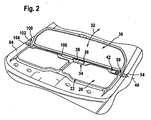
- the wind stop base 20 is provided with a drive device designated as a whole by 34, which preferably comprises a drive motor, in particular an electric motor 36 and a transmission 38, with which the wind deflector 30 for performing a pivoting movement about an axis 40th is drivable ( Fig. 2 ).
- a drive device designated as a whole by 34 which preferably comprises a drive motor, in particular an electric motor 36 and a transmission 38, with which the wind deflector 30 for performing a pivoting movement about an axis 40th is drivable ( Fig. 2 ).
- the drive device 34 is still associated with a control unit 42, which on the one hand detects a pivot position of the wind deflector 30 and on the other hand, according to a control unit 42 predetermined position of the wind deflector 30 controls the drive means 34.
- an energy transfer device 50 is provided, which is arranged on the Windstopbasis 20 first element 52 and at the Body 14 arranged second element 54 which allow in the first embodiment, a power supply by contacting electrical contacts.
- the first element 52 is designed as a plug 60 extending in a plug-in direction 56, which has two contact surfaces 62 and 64 which follow one another in the plug-in direction and which are formed, for example, by lateral surfaces of the plug 60 and are electrically insulated from one another ( Fig. 3 ).
- the plug 60 can be inserted in the plug-in direction 56 into a plug receptacle 70, which has two contact clips 72, 74 in an inner space 76 which, when the plug 60 is plugged into the inner space 76, make contact with the contact surfaces 62 and 64, respectively.
- the second element 54 forming plug receptacle 70 is connected with their contact bars 72, 74 to the electrical system 44 of the body 14 and thus able to supply the arranged in the Windstopbasis 20 drive means 34 and the control unit 42 with energy.
- the Windstopbasis 20 at the height of the belt line 16 of the body 14 is disposed between side walls 82 and 84 of the body, for example, the second elements 54 performing plug receptacle 70 is disposed in the side wall 82, so that the interior 76 via an opening 86 is accessible, which is in the region of a passenger compartment of the body 14 facing inner lining 88 of the side wall 82, so that through this opening 86 of the plug 60 in the connector receptacle 70, which is integrated as a whole in the side wall 82, can be inserted.
- the plug 60 simultaneously forms a fixing bolt for mechanically fixing the Windstopbasis 20 relative to the body 14, in particular the side wall 82 thereof, and the plug receptacle 70 forms a mechanically correspondingly stable Fixierfact for the fixing bolt.
- a function control 90 for conventional vehicle functions which may also be formed by a plurality of function control units for example, as in Fig. 2 illustrated, on the opposite side of the power transmission unit 50 Windstop dressed 10, a signal transmission unit 100 is provided which also works in the simplest case with touching electrical contacts.
- the signal transmission unit 100 comprises a first transmission element 102 provided on the wind stop base 20 and a second transmission element 104 integrated in the side wall 84, which represent a separation point from a control line 106 guided from the function control 90 to the control unit 42.
- the first transmission element 102 and the second transmission element 104 are also formed as a plug or plug receptacle and also integrated into a fixing or a Fixierfact for mechanically fixing the Windstopbasis 20 to the body 14 between the side walls 82 and 84, so that on the fixation the wind stop base 20 on the side wall 84 at the same time the control line 106 between the control unit 42 and the function control 90 can be closed by contacting contacts.
- the first transmission element 102 according to the plug 60 and the second transmission element 104 is formed and executed according to the connector receptacle 70, however, in this case, the plug 60 is movable relative to the Windstopbasis 20 in the direction of insertion 56, while the plug 60th the power transmission device is fixedly connected to the wind stop base 20.
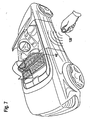
- control unit 42 wirelessly communicates with a portable handset 120, so that by the manual operation 120 is also possible to move the wind deflector 30 between the operative position and the inoperative position back and forth.
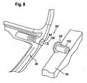
- FIG Fig. 8 In a second embodiment of a wind stop device according to the invention, shown in FIG Fig. 8 , those parts which are identical to those of the first embodiment are given the same reference numerals, so that with respect to the description thereof, reference is made to the explanations of the first embodiment in its entirety.
- the energy transfer device 50 ' is designed as a non-contact energy transfer device, wherein the first element 52', arranged on the Windstopbasis 20, and the second element 54 ', integrated into the side wall 82, cooperate without contact.
- an inductive coupling takes place between the second element 54 'and the first element 52', and thus an induction of energy is transferred from the on-board network 44 of the convertible vehicle 12 to the windstop base 20.
- the fixation of the Windstopbasis 20 takes place in a conventional manner via a mechanical plug pin 130 which is inserted into a socket pin receptacle 132, wherein preferably the elements 52 'and 54' can be arranged coaxially to the socket pin 130.
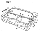
- the wind stop device is additionally ( Fig. 9 ) on the opposite side of the Windstopbasis 20 also via a locking pin 140 which is inserted into a socket pin receptacle 142, fixed to the body 14, wherein the two locking pin receptacles 132 and 142 are integrated into the respective side walls 82 and 84, respectively.
- the second element 54 is integrated into the side wall 82, preferably so that it is arranged on one of the windstop base 20 facing side of the side wall 82, preferably in the region of the inner lining 88.
- the first transmission element 102 'and the second transmission element 104' of the signal transmission unit 100 ' are provided in the region of the plug pin 140 and the socket pin receptacle 142, which preferably also contact one another without contact interact.
- the second embodiment works in the same way as the first embodiment, so that with regard to the description of the individual functions and the interaction, in particular with the function control 90, the statements on the first embodiment can be made in full.
- the power transmission device 50 'with the first element 52' and the second element 54 'coaxial with the socket pins 130 it is not absolutely necessary to arrange the power transmission device 50 'with the first element 52' and the second element 54 'coaxial with the socket pins 130. It is equally possible, the energy transfer device 50 'with the first Element 52 'and the second member 54' eccentrically to the socket pin 130, for example, at any point of a cover 150 of the cover 22 to arrange, in so far as it is parallel to an element of the body 14, for example, one of the side walls 82, 84 extends.
- the signal transmission unit 100 'with the first transmission element 102' can be arranged anywhere on the cover frame 150 insofar as it runs parallel to an element of the body 14, for example one of the side walls 82, 84, in which case the corresponding one second transmission element 104 is disposed in the respective area of the body adjacent to the cover frame 150, for example the side walls 82, 84.
Abstract
Description
Die Erfindung betrifft eine Windstopeinrichtung für Kraftfahrzeuge, insbesondere für Cabriofahrzeuge, umfassend eine fahrzeugfest montierbare Windstopbasis, an welcher ein sich in einer Windschottfläche erstreckendes Windschott zwischen einer wirksamen Stellung und einer unwirksamen Stellung bewegbar gelagert ist, und eine Antriebseinrichtung zum Bewegen des Windschotts zwischen der unwirksamen und der wirksamen Stellung und umgekehrt.The invention relates to a Windstopeinrichtung for motor vehicles, especially for convertible vehicles, comprising a vehicle fixed windstop base on which a wind deflector extending in a wind deflector between an operative position and an inoperative position is movably mounted, and a drive means for moving the wind deflector between the ineffective and the effective position and vice versa.
Derartige Windstopeinrichtungen sind beispielsweise aus der
Der Erfindung liegt daher die Aufgabe zugrunde, eine Windstopeinrichtung der gattungsgemäßen Art derart zu verbessern, dass ein Betreiben derselben optimaler möglich ist.The invention is therefore based on the object to improve a Windstopeinrichtung of the generic type such that an operation of the same is possible optimally.
Diese Aufgabe wird bei einer Windstopeinrichtung der eingangs beschriebenen Art erfindungsgemäß dadurch gelöst, dass der Antriebseinrichtung Energie aus einem Bordnetz des Kraftfahrzeugs mittels einer Energieübertragungseinrichtung zuführbar ist und dass die Energieübertragungseinrichtung ein erstes, an der Windstopbasis angeordnetes Element und ein zweites, an einer Seitenwand der Karosserie des Kraftfahrzeugs angeordnetes Element umfasst, die bei an dem Kraftfahrzeug in Funktionsstellung montierter Windstopeinrichtung Energie vom Bordnetz des Kraftfahrzeugs auf die an der Windstopbasis angeordnete Antriebseinrichtung übertragen, und dass das erste Element und das zweite Element in einer Fixiereinrichtung zum Festlegen der Windstopbasis an der Karosserie integriert sind.This object is achieved in a Windstopeinrichtung of the type described above according to the invention that the drive means energy from an electrical system of the motor vehicle by means of an energy transfer device can be supplied and that the energy transfer device a first, arranged on the Windstopbasis element and a second, on a side wall of the body Motor vehicle arranged element comprises, which is mounted on the motor vehicle in functional position Windstopeinrichtung Transferring energy from the electrical system of the motor vehicle to the arranged on the Windstopbasis drive device, and that the first element and the second element are integrated in a fixing device for fixing the Windstopbasis to the body.
Der Vorteil der erfindungsgemäßen Lösung ist darin zu sehen, dass die erfindungsgemäße Energieübertragungseinrichtung dann stets in der Lage ist, Energie zu übertragen, wenn die Windstopeinrichtung an dem Kraftfahrzeug in Funktionsstellung montiert ist, da in der Funktionsstellung der Windstopeinrichtung zwangsläufig das erste Element der Energieübertragungseinrichtung sowie das zweite Element der Energieübertragungseinrichtung derart positioniert sind, dass diese in der Lage sind, Energie von dem Bordnetz der Karosserie auf die Windstopbasis zu übertragen, wobei die Windstopeinrichtung mechanisch durch Verbinden der Windstopbasis mit der Karosserie des Fahrzeugs gleichzeitig fixiert werden kann und somit in diesem Fall die erfindungsgemäße Energieübertragungseinrichtung in einfacher Weise und optisch völlig unauffällig realisierbar ist.The advantage of the solution according to the invention is the fact that the energy transfer device according to the invention is then always able to transfer energy when the wind stop device is mounted on the motor vehicle in functional position, since in the functional position of the wind stop device inevitably the first element of the energy transfer device and the second element of the energy transmission device are positioned so that they are able to transfer energy from the electrical system of the body to the Windstopbasis, wherein the Windstopeinrichtung can be mechanically fixed simultaneously by connecting the Windstopbasis with the body of the vehicle and thus in this case Energy transfer device according to the invention in a simple manner and visually completely inconspicuous realizable.
Prinzipiell wäre es denkbar, das erste Element der Energieübertragungseinrichtung und das zweite Element der Energieübertragungseinrichtung als separate Elemente auszubilden, die einerseits an der Karosserie und andererseits an der Windstopbasis angeordnet sind.In principle, it would be conceivable to design the first element of the energy transmission device and the second element of the energy transmission device as separate elements, which are arranged on the one hand on the bodywork and on the other hand on the windstop base.
Besonders günstig ist es, wenn das erste Element in der Windstopbasis integriert angeordnet ist, da dann ein optisches Design der Windstopbasis möglich ist, bei welcher das Vorhandensein des ersten Elements der Energieübertragungseinrichtung völlig unauffällig ist.It is particularly advantageous if the first element is arranged integrated in the wind stop base, since then an optical design of the wind stop base is possible, in which the presence of the first element of the energy transmission device is completely inconspicuous.
Noch vorteilhafter ist es, wenn das zweite Element in einer Seitenwand der Karosserie integriert angeordnet ist, da somit auch das zweite Element der Energieübertragungseinrichtung völlig unauffällig und vom Design optimiert in der Karosserie des Kraftfahrzeugs angeordnet werden kann.It is even more advantageous if the second element is arranged integrally in a side wall of the body, since thus also the second element of the energy transmission device can be arranged inconspicuously and optimally optimized in the bodywork of the motor vehicle.
Besonders günstig ist es dabei, wenn das zweite Element in einer Innenverkleidung der Seitenwand der Karosserie integriert ist.It is particularly advantageous if the second element is integrated in an inner lining of the side wall of the body.
Hinsichtlich der Übertragung der Energie mit der erfindungsgemäßen Windstopeinrichtung wurden im Zusammenhang mit der bisherigen Erläuterung der einzelnen Ausführungsbeispiele keine näheren Angaben gemacht.With regard to the transmission of energy with the Windstopeinrichtung invention no further details have been made in connection with the previous explanation of the individual embodiments.
So sieht ein erstes Ausführungsbeispiel vor, dass das erste und das zweite Element der Energieübertragungseinrichtung über sich berührende elektrische Kontaktflächen elektrische Energie übertragen.Thus, a first exemplary embodiment provides that the first and the second element of the energy transmission device transmit electrical energy via contacting electrical contact surfaces.
Eine derartige, über sich berührende elektrische Kontaktflächen erfolgende Energieübertragung, ist eine sehr kostengünstig realisierbare Lösung.Such, over touching electrical contact surfaces taking place energy transfer is a very cost-effective solution.
Besonders zweckmäßig ist es hierbei, wenn das erste und das zweite Element als Steckkontaktelemente ausgebildet sind, das heißt wenn eines der Elemente ein Stecker und das andere der Elemente eine Steckeraufnahme bildet.It is particularly useful here, when the first and the second element are designed as plug contact elements, that is, when one of the elements forms a plug and the other of the elements a plug receptacle.
Alternativ zum Vorsehen von sich berührenden elektrischen Kontaktflächen zur Energieübertragung sieht ein weiteres vorteilhaftes Ausführungsbeispiel vor, dass das erste und das zweite Element der Energieübertragungseinrichtung berührungslos elektrische Energie übertragen.As an alternative to the provision of contacting electrical contact surfaces for energy transmission, another advantageous exemplary embodiment provides that the first and the second element of the energy transmission device transmit electrical energy without contact.
Eine derartige berührungslose Übertragung von elektrischer Energie erfolgt im einfachsten Fall über elektromagnetische Induktion.Such a contactless transmission of electrical energy takes place in the simplest case via electromagnetic induction.
Eine derartige Lösung hat den großen Vorteil, dass damit keine elektrischen Kontakte zwischen den Elementen der Energieübertragungseinrichtung erforderlich sind und somit es lediglich erforderlich ist, dass die beiden Elemente der Energieübertragungseinrichtung in geeigneter Position relativ zueinander angeordnet werden, um die elektrische Energie von dem Bordnetz der Karosserie auf die Windstopbasis zu übertragen.Such a solution has the great advantage that no electrical contacts between the elements of the energy transmission device are required and thus it is only necessary that the two elements of the energy transmission device are arranged in a suitable position relative to each other to the electrical energy from the electrical system of the body to transfer to the windstop base.
Im Rahmen der erfindungsgemäßen Lösung ist es möglich, die Bewegungen des Windschotts über eine im Kraftfahrzeug vorgesehene Steuerung zu steuern, die die Energiezufuhr zu der Antriebseinrichtung ein- und ausschalten oder auch umpolen kann. Damit ist jedoch keine Positionserfassung der jeweiligen Stellung des Windschotts möglich.In the context of the solution according to the invention, it is possible to control the movements of the wind deflector via a controller provided in the motor vehicle, which can switch the energy supply to the drive device on and off or even reverse polarity. This, however, no position detection of the respective position of the wind deflector is possible.
Darüber hinaus wird die eingangs genannte Aufgabe alternativ oder ergänzend zu den bislang beschriebenen Lösungen erfindungsgemäß dadurch gelöst, dass der Antriebseinrichtung eine Steuereinheit zugeordnet ist, welche die Antriebseinrichtung zum Bewegen des Windschotts zwischen der unwirksamen und der wirksamen Stellung und umgekehrt ansteuert, dass die Steuereinheit mit einer fahrzeugseitigen Funktionssteuerung kommuniziert, dass eine Signalübertragungseinheit vorgesehen ist, welche ein erstes, an der Windstopbasis angeordnetes Übertragungselement und ein zweites, an einer Seitenwand der Karosserie angeordnetes Übertragungselement umfasst, und die Übertragungselemente in einer Fixiereinrichtung zum Festlegen der Windstopbasis an der Karosserie integriert sind.In addition, the object mentioned is achieved alternatively or in addition to the previously described solutions according to the invention that the drive means is associated with a control unit which controls the drive means for moving the wind deflector between the inoperative and the active position and vice versa that the control unit with a On the vehicle-side function control communicates that a signal transmission unit is provided, which comprises a first, arranged on the Windstopbasis transmission element and a second, arranged on a side wall of the body transmission element, and the transmission elements are integrated in a fixing device for fixing the Windstopbasis to the body.
Ein Vorsehen einer derartigen Steuereinheit hat den Vorteil, dass damit Steuerungsintelligenz auf die Windstopeinrichtung verlagert werden kann und somit beispielsweise in der Windstopbasis bereits ein Abfragen von Stellungen des Windschotts relativ zur Windstopbasis, das heißt beispielsweise Neigestellungen des Windschotts relativ zur Windstopbasis, möglich ist und folglich dann entsprechend den vorhandenen Neigestellungen eine weitere Steuerung von Bewegungen des Windschotts erfolgen kann. Außerdem ist durch die einfach realisierte Kommunikation mit der fahrzeugseitigen Funktionssteuerung der Bedienungskomfort verbessert.Provision of such a control unit has the advantage that control intelligence can thus be transferred to the wind stop device and thus, for example, in the wind stop base it is already possible to interrogate positions of the wind block relative to the wind stop base, that is, for example, tilting of the wind block relative to the wind stop base, and consequently according to the existing tilting positions, a further control of movements of the wind deflector can take place. In addition, the ease of communication with the on-board function control improves ease of use.
Unter einer fahrzeugseitigen Funktionssteuerung sind dabei Steuereinheiten des Cabriofahrzeugs zu verstehen, die einzelne Funktionen des Kraftfahrzeugs erfassen und/oder anzeigen und/oder steuern.Control functions of the convertible vehicle, which detect and / or display and / or control individual functions of the motor vehicle, are to be understood here as an on-vehicle function control.
Beispielsweise fällt unter den Begriff "fahrzeugseitige Funktionssteuerung" eine Steuereinheit für eine Steuerung von Anzeigen am Armaturenbrett, eine Steuereinheit für ein Erfassen von Funktionstasten am Armaturenbrett, eine Steuereinheit für ein Erfassen und Steuern von Fensterpositionen und/oder eine Steuereinheit für ein Steuern eines Verdecks.For example, the term "on-vehicle function control" includes a control unit for on-dash display control, a dashboard function key detection unit, a window position detection and control unit, and / or a roof control unit.
Eine derartige Steuereinheit könnte beispielsweise so ausgebildet sein, dass diese eigene, beispielsweise an der Windstopeinrichtung vorgesehene oder in Wechselwirkung mit der Steuereinheit stehende tragbare, Bedienungselemente aufweist, so dass durch Betätigen dieser Bedienungselemente die einzelnen Funktionen des Windschotts, insbesondere das Bewegen des Windschotts zwischen der wirksamen Stellung und der unwirksamen Stellung, steuerbar sind.Such a control unit could for example be designed so that this own, provided for example on the Windstopeinrichtung or interacting with the control unit portable, controls, so that by pressing these controls the individual functions of the wind deflector, in particular moving the wind deflector between the effective Position and the inoperative position, are controllable.
Diese Übertragungselemente können prinzipiell als separate Übertragungselemente vorgesehen sein.These transmission elements can in principle be provided as separate transmission elements.
Um ein Design einer Windstopeinrichtung optimieren zu können, ist vorzugsweise vorgesehen, dass das erste Übertragungselement in die Windstopbasis integriert ist.In order to be able to optimize a design of a wind stop device, it is preferably provided that the first transmission element is integrated in the wind stop base.
Ferner lässt sich ein Design der Karosserie des Kraftfahrzeugs auch dann optimieren, wenn das zweite Übertragungselement in die Seitenwand der Karosserie integriert ist, insbesondere wenn das zweite Übertragungselement in eine Innenverkleidung der Seitenwand der Karosserie integriert ist.Furthermore, a design of the body of the motor vehicle can also be optimized if the second transmission element is integrated into the side wall of the body, in particular if the second transmission element is integrated in an inner lining of the side wall of the body.
Hinsichtlich der Art der Wechselwirkung der Übertragungselemente wurden bislang keine näheren Angaben gemacht. So sieht eine erste, konstruktiv einfach zu realisierende Lösung vor, dass die Übertragungselemente über sich berührende elektrische Kontaktflächen miteinander wechselwirken.With regard to the nature of the interaction of the transmission elements so far no further details have been made. Thus, a first, structurally simple to implement solution provides that the transmission elements interact with each other via contacting electrical contact surfaces.
Beispielsweise wäre es dabei denkbar, die Übertragungselemente als Steckkontaktelemente auszubilden, so dass eines derselben als Stecker und das andere als Steckeraufnahme integriert ist.For example, it would be conceivable to form the transmission elements as plug-in contact elements, so that one of them is integrated as a plug and the other as a plug receptacle.
Alternativ zum Vorsehen von sich berührenden elektrischen Kontaktflächen sieht eine weitere Lösung vor, dass die Übertragungselemente berührungslos miteinander wechselwirken.As an alternative to the provision of contacting electrical contact surfaces, a further solution provides that the transmission elements interact with one another without contact.
Eine derartige berührungslose Wechselwirkung lässt sich beispielsweise dadurch realisieren, dass die Übertragungselemente induktiv miteinander wechselwirken.Such a contactless interaction can be realized for example by the fact that the transmission elements interact inductively with each other.
Eine Alternative zu einer induktiven Wechselwirkung sieht vor, dass die Übertragungselemente optisch miteinander wechselwirken.An alternative to an inductive interaction provides that the transmission elements optically interact with each other.
Im Falle des Vorsehens einer Steuereinheit in der Windstopeinrichtung ist es - wie bereits beschrieben - denkbar, unmittelbar an der Windstopbasis oder dem Windschott Bedienelemente vorzusehen.In the case of the provision of a control unit in the wind stop device, it is conceivable, as already described, to provide operating elements directly on the wind stop base or wind deflector.
Alternativ oder ergänzend zu den vorstehend beschriebenen Lösungen des Betriebs der Steuereinheit sieht eine weitere erfindungsgemäße Lösung vor, dass die Steuereinheit mit einer tragbaren Handbedienung kommuniziert.As an alternative or in addition to the solutions of the operation of the control unit described above, a further solution according to the invention provides that the control unit communicates with a portable manual control.
Dabei könnten die Handbedienung und die Steuereinheit durch eine Leitung miteinander verbunden sein. Besonders vorteilhaft ist es jedoch, wenn die Handbedienung und die Steuereinheit berührungslos miteinander kommunizieren.The manual control and the control unit could be connected by a line. However, it is particularly advantageous if the manual control and the control unit communicate with each other without contact.
Alternativ zu einer direkten berührungslosen Wechselwirkung der Steuereinheit mit der Handbedienung sieht eine weitere Lösung vor, dass die Steuereinheit über die fahrzeugseitige Funktionssteuerung mit der Handbedienung kommuniziert, wobei die fahrzeugseitige Funktionssteuerung beispielsweise als Funktionssteuereinheit für eine Fahrzeugverriegelung ausgebildet sein kann.As an alternative to a direct non-contact interaction of the control unit with the manual control, another solution provides that the control unit communicates with the manual control via the vehicle-side function control, wherein the vehicle-side function control can be embodied, for example, as a function control unit for a vehicle lock.
Hierbei ist es besonders vorteilhaft, wenn die Funktionssteuerung berührungslos mit der tragbaren Handbedienung kommuniziert.It is particularly advantageous if the function controller communicates contactlessly with the portable manual control.
Hinsichtlich der einzelnen Funktionen, insbesondere der Korrelation der Stellung des Windschotts mit einzelnen Funktionen des Kraftfahrzeugs wurden bislang keine näheren Angaben gemacht.With regard to the individual functions, in particular the correlation of the position of the wind deflector with individual functions of the motor vehicle, no further details have so far been given.
So sieht eine vorteilhafte Lösung vor, dass die Funktionssteuerung über die Steuereinheit ein bewegen des Windschotts von der unwirksamen Stellung in die wirksame Stellung veranlasst, wenn das Kraftfahrzeug eine vorgebbare Geschwindigkeit überschreitet.Thus, an advantageous solution provides that the function control via the control unit causes the wind deflector to move from the inoperative position to the active position when the motor vehicle exceeds a predeterminable speed.
Alternativ oder ergänzend hierzu sieht eine weitere vorteilhafte Ausführungsform vor, dass die Funktionssteuerung über die Steuereinheit ein Bewegen des Windschotts von der unwirksamen Stellung in die wirksame Stellung veranlasst, wenn ein Verdeck des Kraftfahrzeugs geöffnet wird.Alternatively or additionally thereto, a further advantageous embodiment provides that the function control via the control unit causes the wind deflector to move from the inoperative position to the active position when a top of the motor vehicle is opened.
Alternativ oder ergänzend sieht eine weitere Ausführungsform vor, dass die Funktionssteuerung über die Steuereinheit ein Bewegen des Windschotts von der wirksamen in die unwirksame Stellung veranlasst, wenn ein Rückwärtsgang eingelegt wird.Alternatively or additionally, a further embodiment provides that the function control via the control unit causes a movement of the wind deflector from the active to the inoperative position when a reverse gear is engaged.
Ferner sieht eine Ausführungsform alternativ oder ergänzend zu den bisherigen Funktionen vor, dass die Funktionssteuerung über die Steuereinheit ein Bewegen des Windschotts von der unwirksamen Stellung in die wirksame Stellung veranlasst, wenn alle Scheiben des Kraftfahrzeugs hochgefahren werden.Furthermore, an embodiment provides, as an alternative or in addition to the previous functions, that the function control via the control unit causes a movement of the wind deflector from the inoperative position to the operative position when all the windows of the motor vehicle are started up.
Schließlich sieht eine Ausführungsform alternativ oder ergänzend zu den bisherigen Lösungen vor, dass die Funktionssteuerung über die Steuereinheit ein Bewegen des Windschotts zwischen einer unwirksamen Stellung und einer wirksamen Stellung oder umgekehrt veranlasst, wenn eine entsprechende Bedientaste am Fahrzeug betätigt wird.Finally, an embodiment provides as an alternative or in addition to the previous solutions, that the function control via the control unit causes a movement of the wind deflector between an inoperative position and an operative position or vice versa, when a corresponding control button on the vehicle is operated.
Die vorstehend genannten Funktionsmodi der Funktionssteuerung können fest vorgegeben sein.The aforementioned functional modes of the function control can be fixed.
Besonders günstig ist jedoch eine Lösung bei welcher die einzelnen Funktionsmodi - einzeln oder in Gruppen oder als Gesamtheit - aktivierbar und deaktivierbar sind.However, a solution is particularly favorable in which the individual functional modes - individually or in groups or as a whole - can be activated and deactivated.
Die eingangs genannte Aufgabe wird nicht nur durch eine Windstopeinrichtung der bislang beschriebenen Art entsprechend den einzelnen Ausführungsformen gelöst, sondern auch durch ein Cabriofahrzeug, welches mit einer oder mehreren Ausführungsformen der vorstehend beschriebenen Windstopeinrichtung versehen ist.The aforementioned object is achieved not only by a Windstopeinrichtung of the type described above according to the individual embodiments, but also by a convertible vehicle, which is provided with one or more embodiments of Windstopeinrichtung described above.
Weitere Merkmale und Vorteile der Erfindung sind Gegenstand der nachfolgenden Beschreibung sowie der zeichnerischen Darstellung einiger Ausführungsbeispiele.Further features and advantages of the invention are the subject of the following description and the drawings of some embodiments.
In der Zeichnung zeigen:
- Fig. 1
- eine perspektivische Darstellung eines ersten Ausführungsbeispiels einer erfindungsgemäßen Windstopeinrichtung, montiert an einem Kraftfahrzeug, wobei ein Windschott der Windstopeinrichtung in seiner wirksamen Stellung steht;
- Fig. 2
- eine ausschnittsweise perspektivische Darstellung der Windstopeinrichtung am Cabriofahrzeug gemäß
Fig. 1 ; - Fig. 3
- eine vergrößerte Darstellung des ersten Ausführungsbeispiels der erfindungsgemäßen Windstopeinrichtung im Bereich einer Energieübertragungseinrichtung;
- Fig. 4
- eine perspektivische Darstellung eines Armaturenbretts des Cabriofahrzeugs gemäß
Fig. 1 mit Steuertasten für eine Bewegung des Windschotts zwischen der wirksamen und der unwirksamen Stellung; - Fig. 5
- eine schematische Darstellung ähnlich
Fig. 1 mit zusätzlicher Darstellung eines Getriebewahlhebels; - Fig. 6
- eine schematische Darstellung ähnlich
Fig. 1 mit zusätzlicher Darstellung eines Betätigungselements für eine Fenstersteuerung; - Fig. 7
- eine schematische Darstellung ähnlich
Fig. 1 mit einer Handbedienung zum Bewegen des Windschotts zwischen der unwirksamen und der wirksamen Stellung; - Fig. 8
- eine schematische Darstellung ähnlich
Fig. 3 eines zweiten Ausführungsbeispiels einer erfindungsgemäßen Windstopeinrichtung und - Fig. 9
- eine schematische Darstellung ähnlich
Fig. 2 des zweiten Ausführungsbeispiels der erfindungsgemäßen Windstopeinrichtung.
- Fig. 1
- a perspective view of a first embodiment of a Windstopeinrichtung invention, mounted on a motor vehicle, wherein a wind deflector of Windstopeinrichtung is in its operative position;
- Fig. 2
- a partial perspective view of the Windstopeinrichtung on Cabrio vehicle according to
Fig. 1 ; - Fig. 3
- an enlarged view of the first embodiment of the invention Windstopeinrichtung in the region of an energy transfer device;
- Fig. 4
- a perspective view of a dashboard of the convertible according to
Fig. 1 with control buttons for movement of the wind deflector between the operative and the inoperative position; - Fig. 5
- a schematic representation similar
Fig. 1 with additional representation of a gear selector lever; - Fig. 6
- a schematic representation similar
Fig. 1 with additional representation of an actuator for a window control; - Fig. 7
- a schematic representation similar
Fig. 1 with a manual operation for moving the wind deflector between the inoperative and the operative position; - Fig. 8
- a schematic representation similar
Fig. 3 a second embodiment of a Windstopeinrichtung invention and - Fig. 9
- a schematic representation similar
Fig. 2 of the second embodiment of the invention Windstopeinrichtung.
Ein erstes Ausführungsbeispiel einer erfindungsgemäßen Windstopeinrichtung 10, montiert an einer Karosserie 14 eines Cabriofahrzeugs 12, und zwar hinter einer vorderen Sitzreihe 18, umfasst eine Windstopbasis 20, welche als Abdeckung 22 für einen hinter der vorderen Sitzreihe 18 liegenden offenen Bereich 24 der Karosserie 14 dient. An der Windstopbasis 20 ist ein als Ganzes mit 30 bezeichnetes Windschott gehalten, welches relativ zur Windstopbasis 20 zwischen einer sich quer zu einer Gürtellinie 16 der Karosserie erstreckenden wirksamen Stellung und einer sich ungefähr parallel zur Gürtellinie 16 erstreckenden unwirksamen Stellung, wie durch den Pfeil 32 angedeutet, bewegbar ist (
Zum Bewegen des Windschotts 30 in Richtung 32 ist die Windstopbasis 20 mit einer als Ganzes mit 34 bezeichneten Antriebseinrichtung versehen, welche vorzugsweise einen Antriebsmotor, insbesondere einen Elektromotor 36 sowie ein Getriebe 38 umfasst, mit welchen das Windschott 30 zum Ausführen einer Schwenkbewegung um eine Achse 40 antreibbar ist (
Der Antriebseinrichtung 34 ist noch eine Steuereinheit 42 zugeordnet, welche einerseits eine Schwenkposition des Windschotts 30 erkennt und andererseits entsprechend einer der Steuereinheit 42 vorgegebenen gewünschten Stellung des Windschotts 30 die Antriebseinrichtung 34 ansteuert.The
Um die an der Windstopbasis 20 angeordnete Antriebseinrichtung 34 sowie die Steuereinheit 42 mit Energie versorgen zu können, insbesondere mit Energie aus einem Bordnetz 44 des Kraftfahrzeugs 12, ist eine Energieübertragungseinrichtung 50 vorgesehen, welche ein an der Windstopbasis 20 angeordnetes erstes Element 52 und ein an der Karosserie 14 angeordnetes zweites Element 54 umfasst, die bei dem ersten Ausführungsbeispiel eine Energieversorgung durch einander berührende elektrische Kontakte ermöglichen.In order to be able to supply the arranged on the
Beispielsweise ist das erste Element 52 als sich in einer Einsteckrichtung 56 erstreckender Stecker 60 ausgebildet, welcher zwei in der Einsteckrichtung aufeinanderfolgende Kontaktflächen 62 und 64 aufweist, die beispielsweise durch Mantelflächen des Steckers 60 gebildet und elektrisch gegeneinander isoliert sind (
Der Stecker 60 ist in der Einsteckrichtung 56 in eine Steckeraufnahme 70 einsteckbar, welche in einem Innenraum 76 zwei Kontaktbügel 72, 74 aufweist, die bei in den Innenraum 76 eingestecktem Stecker 60 mit den Kontaktflächen 62 bzw. 64 durch Berührung einen elektrischen Kontakt ergeben.The
Diese beispielsweise das zweite Element 54 bildende Steckeraufnahme 70 ist mit ihren Kontaktbügeln 72, 74 mit dem elektrischen Bordnetz 44 der Karosserie 14 verbunden und somit in der Lage, die in der Windstopbasis 20 angeordnete Antriebseinrichtung 34 sowie die Steuereinheit 42 mit Energie zu versorgen.This, for example, the
Da bei der erfindungsgemäßen Windstopeinrichtung die Windstopbasis 20 in Höhe der Gürtellinie 16 der Karosserie 14 zwischen Seitenwänden 82 und 84 der Karosserie angeordnet ist, ist beispielsweise die das zweite Elemente 54 darstellende Steckeraufnahme 70 in der Seitenwand 82 angeordnet, so dass deren Innenraum 76 über eine Öffnung 86 zugänglich ist, welche im Bereich einer einem Fahrgastraum der Karosserie 14 zugewandten Innenverkleidung 88 der Seitenwand 82 liegt, so dass durch diese Öffnung 86 der Stecker 60 in die Steckeraufnahme 70, die als Ganzes in der Seitenwand 82 integriert ist, einsteckbar ist.Since in the wind stop device according to the invention, the
Vorzugsweise bildet bei dem ersten Ausführungsbeispiel der Stecker 60 gleichzeitig einen Fixierbolzen, zur mechanischen Fixierung der Windstopbasis 20 relativ zu der Karosserie 14, insbesondere der Seitenwand 82 derselben, und die Steckeraufnahme 70 bildet eine mechanisch entsprechend stabile Fixieraufnahme für den Fixierbolzen.Preferably, in the first embodiment, the
Um die Steuereinheit 42 der Windstopbasis 20 noch mit Steuersignalen von einer Funktionssteuerung 90 des Cabriofahrzeugs 12, insbesondere einer Funktionssteuerung 90 für übliche Fahrzeugfunktionen, die auch durch mehrere Funktionssteuereinheiten gebildet sein kann, zu versorgen, ist beispielsweise, wie in
Beispielsweise umfasst die Signalübertragungseinheit 100 ein erstes, an der Windstopbasis 20 vorgesehenes Übertragungselement 102 sowie ein zweites, in die Seitenwand 84 integriertes Übertragungselement 104, die eine Trennstelle von einer von der Funktionssteuerung 90 zu der Steuereinheit 42 geführten Steuerleitung 106 darstellen.By way of example, the
Vorzugsweise sind das erste Übertragungselement 102 und das zweite Übertragungselement 104 ebenfalls als Stecker bzw. Steckeraufnahme ausgebildet und ebenfalls in ein Fixierelement bzw. eine Fixieraufnahme zur mechanischen Fixierung der Windstopbasis 20 an der Karosserie 14 zwischen den Seitenwänden 82 und 84 integriert, so dass über die Fixierung der Windstopbasis 20 an der Seitenwand 84 gleichzeitig die Steuerleitung 106 zwischen der Steuereinheit 42 und der Funktionssteuerung 90 durch sich berührende Kontakte geschlossen werden kann.Preferably, the
Im einfachsten Fall ist das erste Übertragungselement 102 entsprechend dem Stecker 60 und das zweite Übertragungselement 104 entsprechend der Steckeraufnahme 70 ausgebildet und ausgeführt, wobei allerdings in diesem Fall der Stecker 60 relativ zur Windstopbasis 20 in Richtung der Einsteckrichtung 56 bewegbar ausgebildet ist, während der Stecker 60 der Energieübertragungseinrichtung fest mit der Windstopbasis 20 verbunden ist.In the simplest case, the
Aufgrund der Verbindung der Steuereinheit 42 mit der Funktionssteuerung 90 des Cabriofahrzeugs 12 besteht nun die Möglichkeit, die Bewegung des Windschotts 30 zwischen der unwirksamen Stellung und der wirksamen Stellung entsprechend verschiedenen Funktionszuständen des Cabriofahrzeugs 12 zu steuern.Due to the connection of the
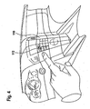
Beispielsweise besteht die Möglichkeit, wie in
Ferner besteht die Möglichkeit, über die Funktionssteuerung 90 eine Fahrtgeschwindigkeit des Cabriofahrzeugs 12 zu erfassen, und durch die Funktionssteuerung 90 bei Überschreiten einer bestimmten vorgegebenen Geschwindigkeit der Steuereinheit 42 das Signal zu übermitteln, dass das Windschott 30 von der unwirksamen Stellung in die wirksame Stellung zu bewegen ist.Furthermore, it is possible to detect a travel speed of the
Ferner besteht, wie in
Ferner besteht, wie in
Ergänzend besteht die Möglichkeit, wie ebenfalls in
Bei dem ersten Ausführungsbeispiel ist weiterhin, wie in
Bei einem zweiten Ausführungsbeispiel einer erfindungsgemäßen Windstopeinrichtung, dargestellt in
Im Gegensatz zum ersten Ausführungsbeispiel ist allerdings die Energieübertragungseinrichtung 50' als berührungslos arbeitende Energieübertragungseinrichtung ausgebildet, wobei das erste Element 52', angeordnet an der Windstopbasis 20, und das zweite Element 54', integriert in die Seitenwand 82, berührungslos zusammenwirken.In contrast to the first embodiment, however, the energy transfer device 50 'is designed as a non-contact energy transfer device, wherein the first element 52', arranged on the
Beispielsweise erfolgt zwischen dem zweiten Element 54' und dem ersten Element 52' eine induktive Kopplung und somit über Induktion eine Energieübertragung von dem Bordnetz 44 des Cabriofahrzeugs 12 auf die Windstopbasis 20.For example, an inductive coupling takes place between the second element 54 'and the first element 52', and thus an induction of energy is transferred from the on-
Die Fixierung der Windstopbasis 20 erfolgt in konventioneller Weise über einen mechanischen Steckbolzen 130, welcher in eine Steckbolzenaufnahme 132 einsteckbar ist, wobei vorzugsweise die Elemente 52' und 54' koaxial zum Steckbolzen 130 angeordnet sein können.The fixation of the
In gleicher Weise wie bei dem ersten Ausführungsbeispiel, ist die Windstopeinrichtung zusätzlich (
In gleicher Weise ist auch das zweite Element 54 in die Seitenwand 82 integriert, vorzugsweise so, dass dieses an einer der Windstopbasis 20 zugewandten Seite der Seitenwand 82, vorzugsweise im Bereich der Innenverkleidung 88 angeordnet ist.Similarly, the
Um gleichzeitig Steuersignale von der Funktionssteuerung 90 auf die Steuereinheit 42 übertragen zu können, sind beim zweiten Ausführungsbeispiel im Bereich des Steckbolzens 140 und der Steckbolzenaufnahme 142 das erste Übertragungselement 102' und das zweite Übertragungselement 104' der Signalübertragungseinheit 100' vorgesehen, die vorzugsweise ebenfalls berührungslos miteinander wechselwirken.In order to be able to simultaneously transmit control signals from the
Als Alternative zu einer induktiven Wechselwirkung zwischen dem ersten Übertragungselement 102' und dem zweiten Übertragungselement 104' ist es ebenfalls denkbar, eine optische Übertragung von Steuersignalen, beispielsweise über Infrarot, vorzusehen.As an alternative to an inductive interaction between the first transmission element 102 'and the second transmission element 104', it is also conceivable to provide an optical transmission of control signals, for example via infrared.
Im Übrigen funktioniert das zweite Ausführungsbeispiel in gleicher Weise wie das erste Ausführungsbeispiel, so dass hinsichtlich der Beschreibung der einzelnen Funktionen und des Zusammenwirkens insbesondere mit der Funktionssteuerung 90 vollinhaltlich auf die Ausführungen zum ersten Ausführungsbeispiel Bezug genommen werden kann.Incidentally, the second embodiment works in the same way as the first embodiment, so that with regard to the description of the individual functions and the interaction, in particular with the
Bei dem zweiten Ausführungsbeispiel ist es jedoch nicht zwingend notwendig, die Energieübertragungseinrichtung 50' mit dem ersten Element 52' und dem zweiten Element 54' koaxial zu den Steckbolzen 130 anzuordnen. Es ist genauso möglich, die Energieübertragungseinrichtung 50' mit dem ersten Element 52' und dem zweiten Element 54' exzentrisch zum Steckbolzen 130, beispielsweise an beliebiger Stelle eines Abdeckrahmens 150 der Abdeckung 22, anzuordnen, insoweit, als dieser parallel zu einem Element der Karosserie 14, beispielsweise einer der Seitenwände 82, 84, verläuft.In the second embodiment, however, it is not absolutely necessary to arrange the power transmission device 50 'with the first element 52' and the second element 54 'coaxial with the socket pins 130. It is equally possible, the energy transfer device 50 'with the first Element 52 'and the second member 54' eccentrically to the
In gleicher Weise kann auch die Signalübertragungseinheit 100' mit dem ersten Übertragungselement 102' an beliebiger Stelle des Abdeckrahmens 150 angeordnet sein, insoweit, als dieser parallel zu einem Element der Karosserie 14, beispielsweise einer der Seitenwände 82, 84, verläuft, wobei dann das entsprechende zweite Übertragungselement 104 in dem jeweiligen an den Abdeckrahmen 150 angrenzenden Bereich der Karosserie, beispielsweise den Seitenwänden 82, 84, angeordnet ist.In the same way, the signal transmission unit 100 'with the first transmission element 102' can be arranged anywhere on the
Claims (24)
- A windbreak device for motor vehicles (12), in particular for cabriolet vehicles, comprising a windbreak base (20) which can be mounted such that it is fixed to the vehicle and on which a wind deflector (30) which extends in a wind deflector area is mounted to be movable between an active position and an inactive position, and a drive device (34) for moving the wind deflector (30) between the inactive and the active position and vice versa, it being possible to supply the drive device (34) with power from an on-board electrical system (44) of the motor vehicle (12) by means of a power transmission device (50), characterized in that the power transmission device (50) comprises a first element (52) which is disposed on the windbreak base (20), and a second element (54) which is disposed on a side wall (82, 84) of the body (14) of the motor vehicle (12), the said elements transferring power from the on-board electrical system (44) of the motor vehicle (12) to the drive device (34) which is disposed on the windbreak base (20) when the windbreak device (10) is mounted on the motor vehicle (12) in a functional position, and in that the first element (52) and the second element (54) are integrated in a fixing device (60, 70) for securing the windbreak base (20) to the vehicle body (14).
- A windbreak device according to Claim 1, characterized in that the first element (52) is disposed such that it is integrated in the windbreak base (20).
- A windbreak device according to Claim 1 or 2, characterized in that the second element (54) is disposed such that it is integrated in a side wall (82, 84) of the vehicle body (14).
- A windbreak device according to any of the preceding claims, characterized in that the first and the second elements (52, 54) of the power transmission device (50) transmit electrical power via touching electrical contact areas (62, 64, 72, 74).
- A windbreak device according to Claim 4, characterized in that the first and the second elements (52, 54) are in the form of plug contact elements (60, 70).
- A windbreak device according to any of Claims 1 to 3, characterized in that the first and the second elements (52', 54') of the power transmission device (50') transmit electrical power in a contact-free manner.
- A windbreak device for motor vehicles (12), in particular for cabriolet vehicles, comprising a windbreak base (20) which can be mounted such that it is fixed to the vehicle and on which a wind deflector (30) which extends in a wind deflector area is mounted to be movable between an active position and an inactive position, and a drive device (34) for moving the wind deflector (30) between the inactive and the active position and vice versa, a control unit (42) being associated with the drive device (34), which unit actuates the drive device (34) to move the wind deflector (30) between the inactive and the active position and vice versa, the control unit (42) communicating with a function control means (90) on the vehicle, and a signal transmission unit (100) being provided, characterized in that the signal transmission unit (100) comprises a first transmission element (102) disposed on the windbreak base (20), and a second transmission element (104) disposed on a side wall (82, 84) of the vehicle body (14), and that the first transmission element (102) and the second transmission element (104) are integrated in a fixing device (60, 70) for securing the windbreak base (20) to the vehicle body (14).
- A windbreak device according to Claim 7, characterized in that the first transmission element (102) is integrated into the windbreak base (20).
- A windbreak device according to Claim 7 or 8, characterized in that the second transmission element (104) is integrated into the side wall (82, 84) of the vehicle body (14).
- A windbreak device according to any of Claims 7 to 9, characterized in that the transmission elements (102, 104) interact with one another via touching electrical contact areas.
- A windbreak device according to any of Claims 7 to 9, characterized in that the transmission elements (102, 104) interact with one another in a contact-free manner.
- A windbreak device according to Claim 11, characterized in that the transmission elements (102, 104) interact with one another in an inductive manner.
- A windbreak device according to Claim 12, characterized in that the transmission elements (102, 104) interact with one another in an optical manner.
- A windbreak device according to any of Claims 7 to 13, characterized in that the control unit (42) communicates with a portable manual operator control means (120).
- A windbreak device according to Claim 14, characterized in that the manual operator control means (120) and the control unit (42) communicate in a contact-free manner.
- A windbreak device according to Claim 14, characterized in that the control unit (42) communicates with the manual operator control means (120) via the function control means (90) on the vehicle.
- A windbreak device according to Claim 16, characterized in that the function control means (90) communicates with the portable manual operator control means (120) in a contact-free manner.
- A windbreak device according to any of Claims 7 to 17, characterized in that the function control means (90) initiates a movement of the wind deflector (30) from the inactive position to the active position by means of the control unit (42) when the motor vehicle (12) exceeds a predefinable speed.
- A windbreak device according to any of Claims 7 to 18, characterized in that the function control means (90) initiates a movement of the wind deflector (30) from the inactive to the active position by means of the control unit (42) when a top (116) of the motor vehicle (12) is opened.
- A windbreak device according to any of Claims 7 to 19, characterized in that the function control means (90) initiates a movement of the wind deflector (30) from the active position to the inactive position by means of the control unit (42) when a reverse gear is engaged.
- A windbreak device according to any of Claims 7 to 20, characterized in that the function control means (90) initiates a movement of the wind deflector (30) from the inactive position to the active position by means of the control unit (42) when all the windows of the motor vehicle (12) are raised.
- A windbreak device according to any of Claims 7 to 21, characterized in that the function control means (90) initiates a movement of the wind deflector (30) between an inactive and an active position or vice versa via the control unit (42) when a corresponding control button (112) in the motor vehicle (12) is operated.
- A windbreak device according to any of Claims 16 to 22, characterized in that the individual function modes of the function control means can be activated and deactivated.
- A cabriolet vehicle, characterized in that it is provided with a windbreak device (10) according to any of the preceding claims.
Applications Claiming Priority (1)
| Application Number | Priority Date | Filing Date | Title |
|---|---|---|---|
| DE102006043004A DE102006043004A1 (en) | 2006-09-07 | 2006-09-07 | Wind stop device |
Publications (2)
| Publication Number | Publication Date |
|---|---|
| EP1897737A1 EP1897737A1 (en) | 2008-03-12 |
| EP1897737B1 true EP1897737B1 (en) | 2010-02-17 |
Family
ID=38520757
Family Applications (1)
| Application Number | Title | Priority Date | Filing Date |
|---|---|---|---|
| EP07017438A Not-in-force EP1897737B1 (en) | 2006-09-07 | 2007-09-06 | Wind deflector |
Country Status (4)
| Country | Link |
|---|---|
| US (1) | US7699381B2 (en) |
| EP (1) | EP1897737B1 (en) |
| AT (1) | ATE457888T1 (en) |
| DE (2) | DE102006043004A1 (en) |
Families Citing this family (12)
| Publication number | Priority date | Publication date | Assignee | Title |
|---|---|---|---|---|
| DE102007051987A1 (en) * | 2007-10-31 | 2009-05-20 | Daimler Ag | Wind blocker arrangement |
| DE102008007210A1 (en) * | 2008-02-01 | 2009-08-06 | Wilhelm Karmann Gmbh | Controller operating method for wind deflector i.e. disk body, of cabriolet vehicle, involves implementing or automatically implementing setting or lowering of wind deflector depending on vehicle condition |
| EP2246211B1 (en) * | 2009-04-30 | 2011-06-08 | Fiat Group Automobiles S.p.A. | A wind deflector device for a two-seat convertible |
| DE102009035335A1 (en) | 2009-07-21 | 2011-01-27 | Scambia Industrial Developments Aktiengesellschaft | Drive unit for a wind stop device |
| DE102010005029B4 (en) * | 2010-01-20 | 2021-05-12 | Dr. Ing. H.C. F. Porsche Aktiengesellschaft | Cabriolet with a roof arrangement |
| DE102010004964B4 (en) * | 2010-01-20 | 2021-05-06 | Dr. Ing. H.C. F. Porsche Aktiengesellschaft | Cabriolet with a wind deflector element |
| FR2967096B1 (en) * | 2010-11-10 | 2012-10-26 | Peugeot Citroen Automobiles Sa | DEVICE ANTI-REMOUS ACCESSORY FOR MOTOR VEHICLE DECAPOTABLE |
| DE102014100978A1 (en) * | 2014-01-28 | 2015-07-30 | Scambia Holdings Cyprus Limited | Wind stop device |
| US9221322B2 (en) * | 2014-04-21 | 2015-12-29 | King Penn Industries, Inc. | Device for restricting wind turbulence |
| DE102015113136B4 (en) * | 2015-08-10 | 2022-10-20 | Webasto-Edscha Cabrio GmbH | Cabriolet vehicle with wind deflector |
| USD839805S1 (en) * | 2016-07-12 | 2019-02-05 | King Penn Industries, Inc. | Wind deflector |
| DE102017109950A1 (en) * | 2017-05-09 | 2018-11-15 | Dr. Ing. H.C. F. Porsche Aktiengesellschaft | vehicle component |
Family Cites Families (12)
| Publication number | Priority date | Publication date | Assignee | Title |
|---|---|---|---|---|
| DE8812257U1 (en) | 1988-09-28 | 1989-01-05 | Fuellgraf, Karl-Heinz, 8600 Bamberg, De | |
| DE4338102C2 (en) * | 1993-11-08 | 1996-05-09 | Daimler Benz Ag | Wind deflector for an open passenger car |
| DE4405707C2 (en) | 1994-02-23 | 1997-02-20 | Daimler Benz Ag | Windbreak |
| US5687453A (en) * | 1995-04-17 | 1997-11-18 | Chrysler Corporation | Grounding washer and arrangements for conductive hinge joints |
| DE29615342U1 (en) * | 1996-09-03 | 1996-10-17 | Zalzar Gmbh | Wind deflector for a convertible |
| DE19735158A1 (en) * | 1997-06-26 | 1999-01-07 | Oris Fahrzeugteile Riehle H | Windstop facility |
| DE19910060A1 (en) * | 1999-03-08 | 2000-09-21 | Audi Ag | Vehicle wind bulkhead device for building into a vehicle has a bulkhead element adjusted by a drive motor to operate as a glass pane unit moved by the drive motor from a shut inoperative position into its operative position. |
| US6866394B1 (en) * | 1999-10-04 | 2005-03-15 | Nicholas D. Hutchins | Modules for elongated lighting system |
| DE10320108B4 (en) * | 2003-05-05 | 2006-12-28 | Webasto Ag | Motor vehicle with a foreclosure device |
| DE102004037482A1 (en) | 2004-07-27 | 2006-02-16 | Oris Fahrzeugteile Hans Riehle Gmbh | Wind stop device |
| DE102006024641A1 (en) * | 2006-05-19 | 2007-11-22 | Scambia Industrial Developments Aktiengesellschaft | Protective device for motor vehicles |
| US7533920B2 (en) * | 2006-10-26 | 2009-05-19 | Nissan Technical Center North America, Inc. | Selectively detachable tailgate hinge assembly |
-
2006
- 2006-09-07 DE DE102006043004A patent/DE102006043004A1/en not_active Withdrawn
-
2007
- 2007-09-05 US US11/899,619 patent/US7699381B2/en not_active Expired - Fee Related
- 2007-09-06 AT AT07017438T patent/ATE457888T1/en active
- 2007-09-06 EP EP07017438A patent/EP1897737B1/en not_active Not-in-force
- 2007-09-06 DE DE502007002844T patent/DE502007002844D1/en active Active
Also Published As
| Publication number | Publication date |
|---|---|
| EP1897737A1 (en) | 2008-03-12 |
| ATE457888T1 (en) | 2010-03-15 |
| DE502007002844D1 (en) | 2010-04-01 |
| US20080061599A1 (en) | 2008-03-13 |
| US7699381B2 (en) | 2010-04-20 |
| DE102006043004A1 (en) | 2008-03-27 |
Similar Documents
| Publication | Publication Date | Title |
|---|---|---|
| EP1897737B1 (en) | Wind deflector | |
| EP3194695B1 (en) | Door handle assembly for a motor vehicle | |
| EP3482024B1 (en) | Handle device with a surface-flush handle | |
| EP2054572B2 (en) | Device for opening a vehicle lock and for capturing an image on the exterior of the vehicle | |
| EP2006145B1 (en) | Locking mechanism | |
| EP2786049B1 (en) | Transmission emergency unlocking means | |
| DE102011051214B4 (en) | Tailgate outside handle device | |
| DE102018132665A1 (en) | POSITIONING DEVICE FOR A MOTOR VEHICLE DOOR ELEMENT | |
| DE19631305B4 (en) | Module for mounting on the steering column of a motor vehicle | |
| DE102010029184A1 (en) | Control device for maneuvering motor vehicle, has maneuvering actuation element for controlling maneuvering assistance system | |
| WO2011047649A1 (en) | Handle device having a mechanical return mechanism | |
| WO2017101900A1 (en) | Lock for a motor vehicle | |
| EP3548983B1 (en) | Control device comprising a rocker element for controlling at least one electrical device, motor vehicle component having a control device, motor vehicle, and method for operating a control device | |
| DE202014010524U1 (en) | Door handle assembly for a motor vehicle | |
| EP2477829A1 (en) | Mechanism for sliding roofs | |
| EP3303742A1 (en) | Method for controlling a motor vehicle door lock | |
| EP2491210A1 (en) | Handle device comprising a shell-shaped bearing | |
| DE102005005185B4 (en) | Switching arrangement for a switching element for opening and closing a vehicle wing | |
| EP3864242A1 (en) | Vehicle door handle | |
| EP1900563B1 (en) | Wind stop device | |
| DE102006038465A1 (en) | Shift lever device for operating vehicle gearbox, has cover part covering outer peripheral part of lever body, and comprising vehicle switch for activating electrical on-board device, where opener switches are constituted by membrane switch | |
| DE19907374A1 (en) | Electronic ignition lock system for a motor vehicle | |
| DE10138118A1 (en) | System of control elements for a vehicle interlinks several control elements mechanically by using an electrical contact connection to connect up the elements in series with a contact pick-up. | |
| EP1908906A2 (en) | Motion device for a sliding door of a vehicle | |
| EP3985214B1 (en) | Door handle assembly for a motor vehicle |
Legal Events
| Date | Code | Title | Description |
|---|---|---|---|
| PUAI | Public reference made under article 153(3) epc to a published international application that has entered the european phase |
Free format text: ORIGINAL CODE: 0009012 |
|
| AK | Designated contracting states |
Kind code of ref document: A1 Designated state(s): AT BE BG CH CY CZ DE DK EE ES FI FR GB GR HU IE IS IT LI LT LU LV MC MT NL PL PT RO SE SI SK TR |
|
| AX | Request for extension of the european patent |
Extension state: AL BA HR MK YU |
|
| 17P | Request for examination filed |
Effective date: 20080730 |
|
| 17Q | First examination report despatched |
Effective date: 20080911 |
|
| AKX | Designation fees paid |
Designated state(s): AT BE BG CH CY CZ DE DK EE ES FI FR GB GR HU IE IS IT LI LT LU LV MC MT NL PL PT RO SE SI SK TR |
|
| GRAP | Despatch of communication of intention to grant a patent |
Free format text: ORIGINAL CODE: EPIDOSNIGR1 |
|
| GRAS | Grant fee paid |
Free format text: ORIGINAL CODE: EPIDOSNIGR3 |
|
| GRAA | (expected) grant |
Free format text: ORIGINAL CODE: 0009210 |
|
| AK | Designated contracting states |
Kind code of ref document: B1 Designated state(s): AT BE BG CH CY CZ DE DK EE ES FI FR GB GR HU IE IS IT LI LT LU LV MC MT NL PL PT RO SE SI SK TR |
|
| REG | Reference to a national code |
Ref country code: GB Ref legal event code: FG4D Free format text: NOT ENGLISH |
|
| REG | Reference to a national code |
Ref country code: CH Ref legal event code: EP |
|
| REG | Reference to a national code |
Ref country code: IE Ref legal event code: FG4D Free format text: LANGUAGE OF EP DOCUMENT: GERMAN |
|
| REF | Corresponds to: |
Ref document number: 502007002844 Country of ref document: DE Date of ref document: 20100401 Kind code of ref document: P |
|
| REG | Reference to a national code |
Ref country code: NL Ref legal event code: VDEP Effective date: 20100217 |
|
| LTIE | Lt: invalidation of european patent or patent extension |
Effective date: 20100217 |
|
| PG25 | Lapsed in a contracting state [announced via postgrant information from national office to epo] |
Ref country code: PT Free format text: LAPSE BECAUSE OF FAILURE TO SUBMIT A TRANSLATION OF THE DESCRIPTION OR TO PAY THE FEE WITHIN THE PRESCRIBED TIME-LIMIT Effective date: 20100617 Ref country code: LT Free format text: LAPSE BECAUSE OF FAILURE TO SUBMIT A TRANSLATION OF THE DESCRIPTION OR TO PAY THE FEE WITHIN THE PRESCRIBED TIME-LIMIT Effective date: 20100217 Ref country code: ES Free format text: LAPSE BECAUSE OF FAILURE TO SUBMIT A TRANSLATION OF THE DESCRIPTION OR TO PAY THE FEE WITHIN THE PRESCRIBED TIME-LIMIT Effective date: 20100528 Ref country code: IS Free format text: LAPSE BECAUSE OF FAILURE TO SUBMIT A TRANSLATION OF THE DESCRIPTION OR TO PAY THE FEE WITHIN THE PRESCRIBED TIME-LIMIT Effective date: 20100617 |
|
| PG25 | Lapsed in a contracting state [announced via postgrant information from national office to epo] |
Ref country code: LV Free format text: LAPSE BECAUSE OF FAILURE TO SUBMIT A TRANSLATION OF THE DESCRIPTION OR TO PAY THE FEE WITHIN THE PRESCRIBED TIME-LIMIT Effective date: 20100217 Ref country code: SI Free format text: LAPSE BECAUSE OF FAILURE TO SUBMIT A TRANSLATION OF THE DESCRIPTION OR TO PAY THE FEE WITHIN THE PRESCRIBED TIME-LIMIT Effective date: 20100217 Ref country code: FI Free format text: LAPSE BECAUSE OF FAILURE TO SUBMIT A TRANSLATION OF THE DESCRIPTION OR TO PAY THE FEE WITHIN THE PRESCRIBED TIME-LIMIT Effective date: 20100217 Ref country code: PL Free format text: LAPSE BECAUSE OF FAILURE TO SUBMIT A TRANSLATION OF THE DESCRIPTION OR TO PAY THE FEE WITHIN THE PRESCRIBED TIME-LIMIT Effective date: 20100217 |
|
| REG | Reference to a national code |
Ref country code: IE Ref legal event code: FD4D |
|
| PG25 | Lapsed in a contracting state [announced via postgrant information from national office to epo] |
Ref country code: SE Free format text: LAPSE BECAUSE OF FAILURE TO SUBMIT A TRANSLATION OF THE DESCRIPTION OR TO PAY THE FEE WITHIN THE PRESCRIBED TIME-LIMIT Effective date: 20100217 Ref country code: RO Free format text: LAPSE BECAUSE OF FAILURE TO SUBMIT A TRANSLATION OF THE DESCRIPTION OR TO PAY THE FEE WITHIN THE PRESCRIBED TIME-LIMIT Effective date: 20100217 Ref country code: IE Free format text: LAPSE BECAUSE OF FAILURE TO SUBMIT A TRANSLATION OF THE DESCRIPTION OR TO PAY THE FEE WITHIN THE PRESCRIBED TIME-LIMIT Effective date: 20100217 Ref country code: NL Free format text: LAPSE BECAUSE OF FAILURE TO SUBMIT A TRANSLATION OF THE DESCRIPTION OR TO PAY THE FEE WITHIN THE PRESCRIBED TIME-LIMIT Effective date: 20100217 Ref country code: GR Free format text: LAPSE BECAUSE OF FAILURE TO SUBMIT A TRANSLATION OF THE DESCRIPTION OR TO PAY THE FEE WITHIN THE PRESCRIBED TIME-LIMIT Effective date: 20100518 Ref country code: EE Free format text: LAPSE BECAUSE OF FAILURE TO SUBMIT A TRANSLATION OF THE DESCRIPTION OR TO PAY THE FEE WITHIN THE PRESCRIBED TIME-LIMIT Effective date: 20100217 Ref country code: CY Free format text: LAPSE BECAUSE OF FAILURE TO SUBMIT A TRANSLATION OF THE DESCRIPTION OR TO PAY THE FEE WITHIN THE PRESCRIBED TIME-LIMIT Effective date: 20100217 |
|
| PG25 | Lapsed in a contracting state [announced via postgrant information from national office to epo] |
Ref country code: BG Free format text: LAPSE BECAUSE OF FAILURE TO SUBMIT A TRANSLATION OF THE DESCRIPTION OR TO PAY THE FEE WITHIN THE PRESCRIBED TIME-LIMIT Effective date: 20100517 Ref country code: CZ Free format text: LAPSE BECAUSE OF FAILURE TO SUBMIT A TRANSLATION OF THE DESCRIPTION OR TO PAY THE FEE WITHIN THE PRESCRIBED TIME-LIMIT Effective date: 20100217 Ref country code: SK Free format text: LAPSE BECAUSE OF FAILURE TO SUBMIT A TRANSLATION OF THE DESCRIPTION OR TO PAY THE FEE WITHIN THE PRESCRIBED TIME-LIMIT Effective date: 20100217 |
|
| PLBE | No opposition filed within time limit |
Free format text: ORIGINAL CODE: 0009261 |
|
| STAA | Information on the status of an ep patent application or granted ep patent |
Free format text: STATUS: NO OPPOSITION FILED WITHIN TIME LIMIT |
|
| 26N | No opposition filed |
Effective date: 20101118 |
|
| PG25 | Lapsed in a contracting state [announced via postgrant information from national office to epo] |
Ref country code: DK Free format text: LAPSE BECAUSE OF FAILURE TO SUBMIT A TRANSLATION OF THE DESCRIPTION OR TO PAY THE FEE WITHIN THE PRESCRIBED TIME-LIMIT Effective date: 20100217 |
|
| BERE | Be: lapsed |
Owner name: SCAMBIA INDUSTRIAL DEVELOPMENTS AKTIENGESELLSCHAFT Effective date: 20100930 |
|
| PG25 | Lapsed in a contracting state [announced via postgrant information from national office to epo] |
Ref country code: IT Free format text: LAPSE BECAUSE OF FAILURE TO SUBMIT A TRANSLATION OF THE DESCRIPTION OR TO PAY THE FEE WITHIN THE PRESCRIBED TIME-LIMIT Effective date: 20100217 |
|
| PG25 | Lapsed in a contracting state [announced via postgrant information from national office to epo] |
Ref country code: MC Free format text: LAPSE BECAUSE OF NON-PAYMENT OF DUE FEES Effective date: 20100930 |
|
| PG25 | Lapsed in a contracting state [announced via postgrant information from national office to epo] |
Ref country code: BE Free format text: LAPSE BECAUSE OF NON-PAYMENT OF DUE FEES Effective date: 20100930 |
|
| PG25 | Lapsed in a contracting state [announced via postgrant information from national office to epo] |
Ref country code: MT Free format text: LAPSE BECAUSE OF FAILURE TO SUBMIT A TRANSLATION OF THE DESCRIPTION OR TO PAY THE FEE WITHIN THE PRESCRIBED TIME-LIMIT Effective date: 20100217 |
|
| REG | Reference to a national code |
Ref country code: CH Ref legal event code: PL |
|
| GBPC | Gb: european patent ceased through non-payment of renewal fee |
Effective date: 20110906 |
|
| PG25 | Lapsed in a contracting state [announced via postgrant information from national office to epo] |
Ref country code: LI Free format text: LAPSE BECAUSE OF NON-PAYMENT OF DUE FEES Effective date: 20110930 Ref country code: CH Free format text: LAPSE BECAUSE OF NON-PAYMENT OF DUE FEES Effective date: 20110930 |
|
| PG25 | Lapsed in a contracting state [announced via postgrant information from national office to epo] |
Ref country code: GB Free format text: LAPSE BECAUSE OF NON-PAYMENT OF DUE FEES Effective date: 20110906 |
|
| PG25 | Lapsed in a contracting state [announced via postgrant information from national office to epo] |
Ref country code: LU Free format text: LAPSE BECAUSE OF NON-PAYMENT OF DUE FEES Effective date: 20100906 Ref country code: HU Free format text: LAPSE BECAUSE OF FAILURE TO SUBMIT A TRANSLATION OF THE DESCRIPTION OR TO PAY THE FEE WITHIN THE PRESCRIBED TIME-LIMIT Effective date: 20100818 |
|
| PG25 | Lapsed in a contracting state [announced via postgrant information from national office to epo] |
Ref country code: TR Free format text: LAPSE BECAUSE OF FAILURE TO SUBMIT A TRANSLATION OF THE DESCRIPTION OR TO PAY THE FEE WITHIN THE PRESCRIBED TIME-LIMIT Effective date: 20100217 |
|
| REG | Reference to a national code |
Ref country code: AT Ref legal event code: MM01 Ref document number: 457888 Country of ref document: AT Kind code of ref document: T Effective date: 20120906 |
|
| PG25 | Lapsed in a contracting state [announced via postgrant information from national office to epo] |
Ref country code: AT Free format text: LAPSE BECAUSE OF NON-PAYMENT OF DUE FEES Effective date: 20120906 |
|
| REG | Reference to a national code |
Ref country code: FR Ref legal event code: TP Owner name: SCAMBIA HOLDINGS CYPRUS LIMITED, CY Effective date: 20150105 |
|
| REG | Reference to a national code |
Ref country code: DE Ref legal event code: R082 Ref document number: 502007002844 Country of ref document: DE Representative=s name: HOEGER, STELLRECHT & PARTNER PATENTANWAELTE, DE |
|
| REG | Reference to a national code |
Ref country code: DE Ref legal event code: R081 Ref document number: 502007002844 Country of ref document: DE Owner name: SCAMBIA HOLDINGS CYPRUS LTD., CY Free format text: FORMER OWNER: SCAMBIA INDUSTRIAL DEVELOPMENTS AKTIENGESELLSCHAFT, SCHAAN, LI Effective date: 20150407 Ref country code: DE Ref legal event code: R082 Ref document number: 502007002844 Country of ref document: DE Representative=s name: HOEGER, STELLRECHT & PARTNER PATENTANWAELTE, DE Effective date: 20150407 Ref country code: DE Ref legal event code: R082 Ref document number: 502007002844 Country of ref document: DE Representative=s name: HOEGER, STELLRECHT & PARTNER PATENTANWAELTE MB, DE Effective date: 20150407 Ref country code: DE Ref legal event code: R081 Ref document number: 502007002844 Country of ref document: DE Owner name: BOSAL ACPS HOLDING 2 B.V., NL Free format text: FORMER OWNER: SCAMBIA INDUSTRIAL DEVELOPMENTS AKTIENGESELLSCHAFT, SCHAAN, LI Effective date: 20150407 |
|
| REG | Reference to a national code |
Ref country code: DE Ref legal event code: R082 Ref document number: 502007002844 Country of ref document: DE Representative=s name: HOEGER, STELLRECHT & PARTNER PATENTANWAELTE MB, DE |
|
| REG | Reference to a national code |
Ref country code: FR Ref legal event code: PLFP Year of fee payment: 10 |
|
| REG | Reference to a national code |
Ref country code: FR Ref legal event code: PLFP Year of fee payment: 11 |
|
| REG | Reference to a national code |
Ref country code: DE Ref legal event code: R081 Ref document number: 502007002844 Country of ref document: DE Owner name: ACPS AUTOMOTIVE GMBH, DE Free format text: FORMER OWNER: SCAMBIA HOLDINGS CYPRUS LTD., LIMASSOL, CY Ref country code: DE Ref legal event code: R082 Ref document number: 502007002844 Country of ref document: DE Representative=s name: HOEGER, STELLRECHT & PARTNER PATENTANWAELTE MB, DE Ref country code: DE Ref legal event code: R081 Ref document number: 502007002844 Country of ref document: DE Owner name: BOSAL ACPS HOLDING 2 B.V., NL Free format text: FORMER OWNER: SCAMBIA HOLDINGS CYPRUS LTD., LIMASSOL, CY |
|
| REG | Reference to a national code |
Ref country code: FR Ref legal event code: PLFP Year of fee payment: 12 |
|
| REG | Reference to a national code |
Ref country code: DE Ref legal event code: R082 Ref document number: 502007002844 Country of ref document: DE Representative=s name: HOEGER, STELLRECHT & PARTNER PATENTANWAELTE MB, DE Ref country code: DE Ref legal event code: R081 Ref document number: 502007002844 Country of ref document: DE Owner name: ACPS AUTOMOTIVE GMBH, DE Free format text: FORMER OWNER: BOSAL ACPS HOLDING 2 B.V., VIANEN, NL |
|
| REG | Reference to a national code |
Ref country code: DE Ref legal event code: R082 Ref document number: 502007002844 Country of ref document: DE Representative=s name: HOEGER, STELLRECHT & PARTNER PATENTANWAELTE MB, DE |
|
| PGFP | Annual fee paid to national office [announced via postgrant information from national office to epo] |
Ref country code: FR Payment date: 20190926 Year of fee payment: 13 Ref country code: DE Payment date: 20190918 Year of fee payment: 13 |
|
| REG | Reference to a national code |
Ref country code: DE Ref legal event code: R119 Ref document number: 502007002844 Country of ref document: DE |
|
| PG25 | Lapsed in a contracting state [announced via postgrant information from national office to epo] |
Ref country code: DE Free format text: LAPSE BECAUSE OF NON-PAYMENT OF DUE FEES Effective date: 20210401 Ref country code: FR Free format text: LAPSE BECAUSE OF NON-PAYMENT OF DUE FEES Effective date: 20200930 |