EP1897719A2 - Drive for soft top - Google Patents
Drive for soft top Download PDFInfo
- Publication number
- EP1897719A2 EP1897719A2 EP07015431A EP07015431A EP1897719A2 EP 1897719 A2 EP1897719 A2 EP 1897719A2 EP 07015431 A EP07015431 A EP 07015431A EP 07015431 A EP07015431 A EP 07015431A EP 1897719 A2 EP1897719 A2 EP 1897719A2
- Authority
- EP
- European Patent Office
- Prior art keywords
- drive
- roof
- main bearing
- hood
- lever
- Prior art date
- Legal status (The legal status is an assumption and is not a legal conclusion. Google has not performed a legal analysis and makes no representation as to the accuracy of the status listed.)
- Granted
Links
- 230000008878 coupling Effects 0.000 claims description 20
- 238000010168 coupling process Methods 0.000 claims description 20
- 238000005859 coupling reaction Methods 0.000 claims description 20
- 210000003127 knee Anatomy 0.000 claims description 13
- 230000007306 turnover Effects 0.000 claims description 7
- 210000002414 leg Anatomy 0.000 claims description 4
- 230000001154 acute effect Effects 0.000 claims description 2
- 230000005540 biological transmission Effects 0.000 description 2
- 210000000689 upper leg Anatomy 0.000 description 2
Images

Classifications
-
- B—PERFORMING OPERATIONS; TRANSPORTING
- B60—VEHICLES IN GENERAL
- B60J—WINDOWS, WINDSCREENS, NON-FIXED ROOFS, DOORS, OR SIMILAR DEVICES FOR VEHICLES; REMOVABLE EXTERNAL PROTECTIVE COVERINGS SPECIALLY ADAPTED FOR VEHICLES
- B60J7/00—Non-fixed roofs; Roofs with movable panels, e.g. rotary sunroofs
- B60J7/08—Non-fixed roofs; Roofs with movable panels, e.g. rotary sunroofs of non-sliding type, i.e. movable or removable roofs or panels, e.g. let-down tops or roofs capable of being easily detached or of assuming a collapsed or inoperative position
- B60J7/12—Non-fixed roofs; Roofs with movable panels, e.g. rotary sunroofs of non-sliding type, i.e. movable or removable roofs or panels, e.g. let-down tops or roofs capable of being easily detached or of assuming a collapsed or inoperative position foldable; Tensioning mechanisms therefor, e.g. struts
- B60J7/1226—Soft tops for convertible vehicles
- B60J7/1265—Soft tops for convertible vehicles characterised by kinematic movements, e.g. using parallelogram linkages
Abstract
Description
Die Erfindung betrifft einen Verdeckantrieb für ein von einer Schließposition in eine Ablageposition und umgekehrt überführbares flexibles Fahrzeugdach mit den weiteren Merkmalen des Oberbegriffes des Anspruches 1.The invention relates to a convertible top drive for a flexible vehicle roof which can be converted from a closed position into a storage position and vice versa, having the further features of the preamble of
Ein aus
Aus
Der Erfindung liegt die Aufgabe zugrunde, einen Verdeckantrieb mit den Merkmalen des Oberbegriffes des Anspruches 1 derart auszubilden, dass die Elemente des Verdeckantriebes mit dem Verdeckhauptlager und weiteren daran angelenkten Elementen, insbesondere Dachlenkern eine kompakte, zusammenhängend montierbare Einheit bildet, wobei die Verdeckantriebsteile in ihrer räumlichen Ausdehnung im wesentlichen auf die Ausdehnung des Verdeckhauptlagers beschränkt sind. Diese Aufgabe wird dadurch gelöst, dass ein Stellende des Linearantriebes schwenkbar an einem am Verdeckhauptlager befestigten Umschlaghebel befestigt ist, an dessen freien Ende eine Antriebskoppel vorgesehen ist, die mit einem ersten Ende gelenkig mit dem freien Ende des Umschlaghebels und mit einem zweiten Ende gelenkig mit einem vom Drehpunkt am Verdeckhauptlager beabstandeten Abschnitt des Dachlenkers befestigt ist, wodurch eine Antriebsbewegung des Linearantriebes auf den Dachlenker übertragen werden kann. Als Kern der Erfindung wird gleichsam eine in den Bereich des Verdeckhauptlagers integrierte und daran befestigte Antriebskraftübertragungskette angesehen, die aus dem Linearantrieb, der Antriebskoppel und dem Umschlaghebel besteht. Diese Teile bewegen sich im wesentlichen im Bereich des Verdeckhauptlagers, so dass der Verdeckantrieb insgesamt platzsparend ausgebildet ist. Auch hinsichtlich der Verdeckmontage und insbesondere der Montage der Antriebsteile wird mit Vorteil erreicht, dass das Verdeck oder zumindest Teile davon vormontiert in eine Fahrzeugkarosserie eingesetzt werden können, wozu nur wenige Schrauben erforderlich sind, die das Verdecklager an der Fahrzeugkarosserie haltern. Eine gesonderte Abstützung des Linearantriebes, insbesondere eines Antriebszylinders ist nicht erforderlich. Die Krafteinleitung des Linearantriebes in die Mitglieder der Antriebskette zwischen Linearantrieb und Dachlenker erfolgt zunächst in einer vom Dachlenker weggerichteten Richtung zu einem Umschlaghebel, der innerhalb des Verdeckhauptlagers verschwenkbar ist. An dessen freien Schwenkende befindet sich die Antriebskoppel, die die Schwenkbewegung des Umschlaghebels auf den Dachlenker überträgt, der am Verdeckhauptlager befestigt ist. Mit nur wenigen Antriebsteilen ist damit eine Übertragungskette geschaffen, die im Vergleich zu den relativ ausladenden Elementen beim Stand der Technik platzsparend ist.The invention has the object of providing a convertible top drive with the features of the preamble of
In bevorzugter Ausführungsform greift das Stellende des Linearantriebes an dem Umschlaghebel etwa mittig an, so dass eine Übersetzung des Hubes des Linearantriebes bezogen auf das freie Ende des Umschlaghebels erfolgt. An diesem freien Ende ist zur Bewegungsübertragung die Antriebskoppel vorgesehen, die so an dem Dachlenker angreift, dass dieser von einer Verdeckschließposition in eine Verdecköffnungsposition und umgekehrt verschwenkt werden kann. Die Hubübersetzung durch den in das Verdeckhauptlager integrierten Umschlaghebel erlaubt eine relativ kurze Ausbildung des Linearantriebes bei relativ großen auf dem Dachlenker übertragenen Huben. Der Dachlenker weist an seinem dem Hauptlager zugewandten Ende eine im wesentlichen einen Kniebereich bildende Form auf, wobei die Antriebskoppel im Kniebereich des Dachlenkers drehbeweglich gelagert ist.In a preferred embodiment, the positioning end of the linear drive engages approximately centrally on the envelope lever, so that a translation of the stroke of the linear drive relative to the free end of the envelope lever takes place. At this free end, the drive coupling is provided for transmitting movement, which acts on the roof handlebar, that it can be pivoted from a top closing position in a top opening position and vice versa. The Hubübersetzung by integrated in the convertible top bearing Umschlaghebel allows a relatively short design of the linear drive with relatively large transmitted to the roof handle Huben. The roof link has at its end facing the main bearing on a substantially forming a knee region shape, wherein the drive coupling is rotatably mounted in the knee region of the roof arm.
Die Ansprüche 7 bis 14 stellen in allen Bewegungsphasen des Verdecks eine sichere Krafteinleitung, eine kompakte Ausbildung der Antriebselemente und eine definierte Stellung der Antriebselemente in unterschiedlichen Öffnungs- und Schließphasen sicher.
Die Erfindung ist anhand von Ausführungsbeispielen in den Zeichnungsfiguren näher erläutert. Diese zeigen
- Fig. 1
- die wesentlichen Elemente eines Verdeckantriebes mit dadurch bewegten Dachlenkern in einer ersten, einer Dachschließstellung entsprechenden Position;
- Fig. 2
- die Elemente gern. Fig. 1 in einer zweiten, einer halben Dachöffnung entsprechenden Position;
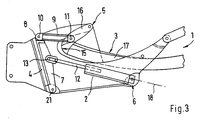
- Fig. 3
- die Elemente gern. Fig. 1 und 2 in einer Dachöffnungsstellung entsprechenden Position.
- Fig. 1
- the essential elements of a convertible top drive with thereby moving roof rails in a first, a roof closed position corresponding position;
- Fig. 2
- the elements like. Figure 1 in a second, half roof opening corresponding position.
- Fig. 3
- the elements like. Fig. 1 and 2 in a roof opening position corresponding position.
Der Verdeckantrieb 1 und das nicht weiter dargestellte, durch den Verdeckantrieb 1 bewegte Fahrzeugdach umfassen einen Linearantrieb 2, einen durch den Linearantrieb 2 bewegten Dachlenker 3, ein Verdeckhauptlager 4, an dem das Festende 5 des Dachlenkers 3 und das Festende 6 des Linearantriebes 2 befestigt sind. Ferner ist ein am Verdeckhauptlager 4 schwenkbar befestigter Umschlaghebel 7 vorgesehen, an dessen freien Ende 8 eine Antriebskoppel 9 angeordnet ist, die mit einem ersten Ende 10 am freien Ende 8 des Umschlaghebels 7 befestigt ist und mit einem zweiten Ende 11 an dem Dachlenker 3 angreift. Der Linearantrieb 2 weist beim dargestellten Ausführungsbeispiel eine linear verschiebbare Stange 12, beispielsweise eine Kolbenstange auf, deren freies Stellende 13 etwa mittig am Umschlaghebel 7 angreift und dadurch in etwa zu einer Bewegungsverdoppelung bezogen auf das freie Ende 8 des Umschlaghebels 7 führt. Der vom Linearantrieb 2 und vom Umschlaghebel 7 benötigte Bewegungsraum ist dadurch begrenzt.The
Keines der Antriebselemente Linearantrieb 2, Umschlaghebel 7 und Antriebskoppel 9 stehen in irgendeiner Bewegungsphase des Verdeckantriebes 1 im wesentlichen über eine obere Außenkontur 14 des Verdeckhauptlagers 4 hinaus, die in Zeichnungsfigur 1 gestrichelt dargestellt ist. Die gestrichelte Außenkontur 14 folgt einerseits den Oberkanten des Verdeckhauptlagers 4, andererseits verläuft es zwischen dem Lagerpunkt am Festende des Dachlenkers 3 und dem Lagerpunkt am Festende des Stützlenkers 19.None of the drive elements
Der Dachlenker 3 weist an seinem dem Verdeckhauptlager 4 zugewandten Ende eine im wesentlichen einen Kniebereich 15 bildende Form auf, wobei die Antriebskoppel 9 im Kniebereich 15 des Dachlenkers 3 an diesem drehbeweglich gelagert ist und die beiden an dem Kniebereich 15 angrenzenden Schenkel 16, 17 einen spitzen Winkel einschließen.The
Die Längsachse 18 des Linearantriebes 2 verlaufen in keiner Bewegungsphase des Verdeckantriebes 1 parallel zueinander, vielmehr schließen beide Elemente in allen Bewegungsphasen einen spitzen Winkel ein. Der Umschlaghebel 7 durchläuft während der Bewegungsphase des Verdeckantriebes 1 im wesentlichen einen Winkelbereich von weniger als 90°.The
Das Fahrzeugverdeck ist neben dem Dachlenker 3 zusätzlich noch durch einen Stützlenker 19 an dem Verdeckhauptlager 4 gelagert, der Verdeckantrieb 1 greift allerdings ausschließlich an dem Dachlenker 3 an und bewegt über diesen alle anderen Dachteile zwangsgesteuert.The vehicle roof is in addition to the
Umschlaghebel 7, Antriebskoppel 9, Linearantrieb 2, der Dachlenker 3 und der Stützlenker 19 bilden mit dem Verdeckhauptlager 4 eine zusammenhängend in eine Fahrzeugkarosserie montierbare Baueinheit. Da an dem Dachlenker 3 und dem Stützlenker 19 weitere Dachteile befestigt bzw. vormontiert sind, kann das gesamte Fahrzeugdach einschließlich des motorischen Antriebes auf einfache Weise in eine Fahrzeugkarosserie eingebaut werden.
Das Verdeckhauptlager 4 ist im wesentlichen u-förmig ausgebildet, in den Innenbereich taucht in Verdeckablageposition gern. Fig. 3 der Kniebereich 15 des Dachlenkers 3 zumindest bereichsweise ein.The top
Aus den Zeichnungsfiguren 1 bis 3 ist noch ersichtlich, dass der Umschlaghebel 7 einen Anschlag 20 aufweist, der in Verdeckablageposition gemäß Fig. 3 die Antriebskoppel 9 beaufschlagt und abstützt. Aus Figur 1 ist außerdem ersichtlich, dass der Umschlaghebel 7 mit der Antriebskoppel 9 in Verdeckschließposition eine im wesentlichen gestreckte Stützstellung einnimmt, wodurch über den Dachlenker 3 eingeleitete Kräfte direkt am Schwenklager 21 zwischen Umschlaghebel 7 und Verdeckhauptlager 4 abgestützt werden.It is still apparent from the drawing figures 1 to 3 that the
- 1 Verdeckantrieb1 convertible top drive
- 2 Linearantrieb2 linear drive
- 3 Dachlenker3 roof rails
- 4 Verdeckhauptlager4 convertible top bearings
- 5 Festende von 35 festivals of 3
- 6 Festende von 26 fortress of 2
- 7 Umschlaghebel7 envelope lever
- 8 freies Ende von 78 free end of 7
- 9 Antriebskoppel9 drive coupling
- 10 erstes Ende von 910 first end of 9
- 11 zweites Ende11 second end
- 12 Stange von 212 pole of 2
- 13 Stellende von 213 positions from 2
- 14 Außenkontur14 outer contour
- 15 Kniebereich von 315 knee area of 3
- 16 Schenkel von 316 thighs of 3
- 17 Schenkel von 317 thighs of 3
- 18 Längsachse18 longitudinal axis
- 19 Stützlenker19 support arms
- 20 Anschlag20 stop
- 21 Schwenklager21 pivot bearings
Claims (14)
Applications Claiming Priority (1)
| Application Number | Priority Date | Filing Date | Title |
|---|---|---|---|
| DE102006042202A DE102006042202A1 (en) | 2006-09-08 | 2006-09-08 | top drive |
Publications (3)
| Publication Number | Publication Date |
|---|---|
| EP1897719A2 true EP1897719A2 (en) | 2008-03-12 |
| EP1897719A3 EP1897719A3 (en) | 2010-03-17 |
| EP1897719B1 EP1897719B1 (en) | 2013-05-22 |
Family
ID=38828377
Family Applications (1)
| Application Number | Title | Priority Date | Filing Date |
|---|---|---|---|
| EP07015431.5A Active EP1897719B1 (en) | 2006-09-08 | 2007-08-07 | Drive for soft top |
Country Status (4)
| Country | Link |
|---|---|
| US (1) | US7775579B2 (en) |
| EP (1) | EP1897719B1 (en) |
| CN (1) | CN101138956B (en) |
| DE (1) | DE102006042202A1 (en) |
Families Citing this family (4)
| Publication number | Priority date | Publication date | Assignee | Title |
|---|---|---|---|---|
| DE102009005033A1 (en) | 2009-01-17 | 2010-07-22 | Magna Car Top Systems Gmbh | Drive device for folding hood at assembly of passenger vehicle, has hood connecting rod and driving motor engaged at hood connecting rod |
| DE102009032956A1 (en) * | 2009-07-14 | 2011-01-20 | Dr. Ing. H.C. F. Porsche Aktiengesellschaft | Device and method for operating a driven by a drive closing part on a means of transport |
| DE102011016781A1 (en) | 2011-04-12 | 2012-10-18 | Magna Car Top Systems Gmbh | Drive for a C-pillar |
| DE102011119432A1 (en) | 2011-11-25 | 2013-05-29 | Magna Car Top Systems Gmbh | Adjustable vehicle roof for cabriolet vehicle, has rear rods in which pressing force is exerted when the roof is transferred from closing position into opening position such that angle between linear drive and hinge rod is increased |
Citations (3)
| Publication number | Priority date | Publication date | Assignee | Title |
|---|---|---|---|---|
| DE889270C (en) | 1950-08-26 | 1953-09-10 | Ford Werke Ag | Folding top for motor vehicles |
| DE4438925C1 (en) | 1994-10-31 | 1995-11-09 | Porsche Ag | Folding roof for motor vehicle |
| US20030146642A1 (en) | 2002-01-05 | 2003-08-07 | Edscha Cabrio-Dachsysteme Gmbh | Top for a convertible vehicle |
Family Cites Families (5)
| Publication number | Priority date | Publication date | Assignee | Title |
|---|---|---|---|---|
| AU2002241660A1 (en) * | 2000-10-20 | 2002-06-11 | Dura Convertible Systems, Inc. | Folding convertible top with integral boot |
| DE10144583B4 (en) * | 2001-09-11 | 2005-03-17 | Edscha Cabrio-Dachsysteme Gmbh | Hood for a convertible vehicle |
| DE10206650A1 (en) * | 2001-12-03 | 2003-09-04 | Cts Fahrzeug Dachsysteme Gmbh | Adjustable vehicle roof |
| FR2846285B1 (en) * | 2002-10-29 | 2004-12-24 | France Design | RETRACTABLE ROOF FOR MOTOR VEHICLE |
| DE102004040728B3 (en) * | 2004-08-20 | 2006-03-30 | Cts Fahrzeug-Dachsysteme Gmbh | Hinged roof for a vehicle |
-
2006
- 2006-09-08 DE DE102006042202A patent/DE102006042202A1/en active Granted
-
2007
- 2007-08-07 EP EP07015431.5A patent/EP1897719B1/en active Active
- 2007-09-07 CN CN2007101536020A patent/CN101138956B/en not_active Expired - Fee Related
- 2007-09-10 US US11/852,526 patent/US7775579B2/en active Active
Patent Citations (3)
| Publication number | Priority date | Publication date | Assignee | Title |
|---|---|---|---|---|
| DE889270C (en) | 1950-08-26 | 1953-09-10 | Ford Werke Ag | Folding top for motor vehicles |
| DE4438925C1 (en) | 1994-10-31 | 1995-11-09 | Porsche Ag | Folding roof for motor vehicle |
| US20030146642A1 (en) | 2002-01-05 | 2003-08-07 | Edscha Cabrio-Dachsysteme Gmbh | Top for a convertible vehicle |
Also Published As
| Publication number | Publication date |
|---|---|
| EP1897719A3 (en) | 2010-03-17 |
| CN101138956B (en) | 2011-07-06 |
| DE102006042202A1 (en) | 2008-03-27 |
| US7775579B2 (en) | 2010-08-17 |
| EP1897719B1 (en) | 2013-05-22 |
| US20080061588A1 (en) | 2008-03-13 |
| CN101138956A (en) | 2008-03-12 |
Similar Documents
| Publication | Publication Date | Title |
|---|---|---|
| EP1721768B1 (en) | Sliding door for a vehicle | |
| DE10205144B4 (en) | Locking device for a folding roof of a vehicle | |
| DE19532567C1 (en) | Convertible hood esp. for motor car | |
| EP0395847B1 (en) | Actuator assembly for a motorised folding top | |
| EP1767388A2 (en) | Pivotable sliding vehicle door , especially for public transport | |
| EP1897719B1 (en) | Drive for soft top | |
| DE102005033537B4 (en) | Adjustment device for components | |
| DE19518071A1 (en) | Vehicle roof opening mechanism actuated by lever next to driver seat | |
| EP1080965A2 (en) | Actuating device for a pivotable element | |
| DE1580603C3 (en) | Operating and locking device for a vehicle sunroof | |
| EP1186455A2 (en) | Movable vehicle roof with tiltable side window | |
| DE102004048405A1 (en) | Kinematics for adjusting a side flap of a cover assembly for vehicles with openable vehicle roof | |
| DE10105771B4 (en) | Locking device for a convertible top | |
| EP2428381B1 (en) | Locking device | |
| DE10225630A1 (en) | Convertible top compartment cover for vehicles, in particular passenger cars | |
| DE10159302C1 (en) | Drive device, for pivot component of automobile cabriolet roof ,has coupling lever acted on by drive coupled to pivot component via knee-lever | |
| DE102007024570B4 (en) | Hinge for a motor vehicle door | |
| EP1848603B1 (en) | Hard top | |
| DE19714106C2 (en) | Convertible vehicle roof | |
| DE10117769B4 (en) | Device for assisting an opening movement of a vehicle flap | |
| EP1705058B1 (en) | Device for holding and removing of objects for daily use | |
| DE102005061978B3 (en) | Hinge device for vehicle flaps and doors has two hinge arms with one end of second arm remote from rotational axis connected to first arm to move in longitudinal direction of latter when both arms are rotated | |
| EP1493645A1 (en) | Switch drive apparatus | |
| DE10356324B4 (en) | Retractable roof of a convertible | |
| EP2338767A1 (en) | Actuating and locking mechanism for a cover for a vehicle |
Legal Events
| Date | Code | Title | Description |
|---|---|---|---|
| PUAI | Public reference made under article 153(3) epc to a published international application that has entered the european phase |
Free format text: ORIGINAL CODE: 0009012 |
|
| AK | Designated contracting states |
Kind code of ref document: A2 Designated state(s): AT BE BG CH CY CZ DE DK EE ES FI FR GB GR HU IE IS IT LI LT LU LV MC MT NL PL PT RO SE SI SK TR |
|
| AX | Request for extension of the european patent |
Extension state: AL BA HR MK YU |
|
| RAP1 | Party data changed (applicant data changed or rights of an application transferred) |
Owner name: DR. ING. H.C. F. PORSCHE AKTIENGESELLSCHAFT |
|
| RAP1 | Party data changed (applicant data changed or rights of an application transferred) |
Owner name: DR. ING. H.C. F. PORSCHE AKTIENGESELLSCHAFT |
|
| PUAL | Search report despatched |
Free format text: ORIGINAL CODE: 0009013 |
|
| AK | Designated contracting states |
Kind code of ref document: A3 Designated state(s): AT BE BG CH CY CZ DE DK EE ES FI FR GB GR HU IE IS IT LI LT LU LV MC MT NL PL PT RO SE SI SK TR |
|
| AX | Request for extension of the european patent |
Extension state: AL BA HR MK RS |
|
| RAP1 | Party data changed (applicant data changed or rights of an application transferred) |
Owner name: DR. ING. H.C. F. PORSCHE AG |
|
| 17P | Request for examination filed |
Effective date: 20100917 |
|
| 17Q | First examination report despatched |
Effective date: 20101020 |
|
| AKX | Designation fees paid |
Designated state(s): DE FR GB IT |
|
| GRAP | Despatch of communication of intention to grant a patent |
Free format text: ORIGINAL CODE: EPIDOSNIGR1 |
|
| GRAS | Grant fee paid |
Free format text: ORIGINAL CODE: EPIDOSNIGR3 |
|
| GRAA | (expected) grant |
Free format text: ORIGINAL CODE: 0009210 |
|
| AK | Designated contracting states |
Kind code of ref document: B1 Designated state(s): DE FR GB IT |
|
| REG | Reference to a national code |
Ref country code: GB Ref legal event code: FG4D Free format text: NOT ENGLISH |
|
| REG | Reference to a national code |
Ref country code: DE Ref legal event code: R096 Ref document number: 502007011783 Country of ref document: DE Effective date: 20130718 |
|
| PLBE | No opposition filed within time limit |
Free format text: ORIGINAL CODE: 0009261 |
|
| STAA | Information on the status of an ep patent application or granted ep patent |
Free format text: STATUS: NO OPPOSITION FILED WITHIN TIME LIMIT |
|
| 26N | No opposition filed |
Effective date: 20140225 |
|
| REG | Reference to a national code |
Ref country code: DE Ref legal event code: R097 Ref document number: 502007011783 Country of ref document: DE Effective date: 20140225 |
|
| REG | Reference to a national code |
Ref country code: FR Ref legal event code: PLFP Year of fee payment: 10 |
|
| REG | Reference to a national code |
Ref country code: FR Ref legal event code: PLFP Year of fee payment: 11 |
|
| REG | Reference to a national code |
Ref country code: FR Ref legal event code: PLFP Year of fee payment: 12 |
|
| PGFP | Annual fee paid to national office [announced via postgrant information from national office to epo] |
Ref country code: IT Payment date: 20180830 Year of fee payment: 12 Ref country code: FR Payment date: 20180827 Year of fee payment: 12 |
|
| PG25 | Lapsed in a contracting state [announced via postgrant information from national office to epo] |
Ref country code: FR Free format text: LAPSE BECAUSE OF NON-PAYMENT OF DUE FEES Effective date: 20190831 |
|
| PG25 | Lapsed in a contracting state [announced via postgrant information from national office to epo] |
Ref country code: IT Free format text: LAPSE BECAUSE OF NON-PAYMENT OF DUE FEES Effective date: 20190807 |
|
| PGFP | Annual fee paid to national office [announced via postgrant information from national office to epo] |
Ref country code: GB Payment date: 20220822 Year of fee payment: 16 |
|
| P01 | Opt-out of the competence of the unified patent court (upc) registered |
Effective date: 20230526 |
|
| PGFP | Annual fee paid to national office [announced via postgrant information from national office to epo] |
Ref country code: DE Payment date: 20230628 Year of fee payment: 17 |
|
| GBPC | Gb: european patent ceased through non-payment of renewal fee |
Effective date: 20230807 |