EP1897576B1 - Dispositif respiratoire portable - Google Patents
Dispositif respiratoire portable Download PDFInfo
- Publication number
- EP1897576B1 EP1897576B1 EP07115407.4A EP07115407A EP1897576B1 EP 1897576 B1 EP1897576 B1 EP 1897576B1 EP 07115407 A EP07115407 A EP 07115407A EP 1897576 B1 EP1897576 B1 EP 1897576B1
- Authority
- EP
- European Patent Office
- Prior art keywords
- breathing device
- valve
- conduit
- motor
- head unit
- Prior art date
- Legal status (The legal status is an assumption and is not a legal conclusion. Google has not performed a legal analysis and makes no representation as to the accuracy of the status listed.)
- Active
Links
- 230000029058 respiratory gaseous exchange Effects 0.000 title claims description 39
- 238000007789 sealing Methods 0.000 claims description 9
- 230000007246 mechanism Effects 0.000 claims description 7
- 238000012544 monitoring process Methods 0.000 claims description 5
- 239000012530 fluid Substances 0.000 description 9
- 230000008901 benefit Effects 0.000 description 5
- 230000000694 effects Effects 0.000 description 4
- 210000004072 lung Anatomy 0.000 description 4
- 210000003205 muscle Anatomy 0.000 description 4
- 241001465754 Metazoa Species 0.000 description 3
- 230000008859 change Effects 0.000 description 3
- 238000010586 diagram Methods 0.000 description 3
- 230000000737 periodic effect Effects 0.000 description 3
- 230000002685 pulmonary effect Effects 0.000 description 3
- 238000004659 sterilization and disinfection Methods 0.000 description 3
- 238000012549 training Methods 0.000 description 3
- CURLTUGMZLYLDI-UHFFFAOYSA-N Carbon dioxide Chemical compound O=C=O CURLTUGMZLYLDI-UHFFFAOYSA-N 0.000 description 2
- 238000004458 analytical method Methods 0.000 description 2
- 238000013500 data storage Methods 0.000 description 2
- 238000011161 development Methods 0.000 description 2
- JYGXADMDTFJGBT-VWUMJDOOSA-N hydrocortisone Chemical compound O=C1CC[C@]2(C)[C@H]3[C@@H](O)C[C@](C)([C@@](CC4)(O)C(=O)CO)[C@@H]4[C@@H]3CCC2=C1 JYGXADMDTFJGBT-VWUMJDOOSA-N 0.000 description 2
- 230000006872 improvement Effects 0.000 description 2
- 238000003780 insertion Methods 0.000 description 2
- 230000037431 insertion Effects 0.000 description 2
- 230000033001 locomotion Effects 0.000 description 2
- 238000004519 manufacturing process Methods 0.000 description 2
- 230000002035 prolonged effect Effects 0.000 description 2
- 230000000717 retained effect Effects 0.000 description 2
- 208000006545 Chronic Obstructive Pulmonary Disease Diseases 0.000 description 1
- 206010011409 Cross infection Diseases 0.000 description 1
- 206010051055 Deep vein thrombosis Diseases 0.000 description 1
- 206010014561 Emphysema Diseases 0.000 description 1
- 102000018997 Growth Hormone Human genes 0.000 description 1
- 108010051696 Growth Hormone Proteins 0.000 description 1
- 206010029803 Nosocomial infection Diseases 0.000 description 1
- 206010047249 Venous thrombosis Diseases 0.000 description 1
- 230000009471 action Effects 0.000 description 1
- 230000002411 adverse Effects 0.000 description 1
- 208000006673 asthma Diseases 0.000 description 1
- QVGXLLKOCUKJST-UHFFFAOYSA-N atomic oxygen Chemical compound [O] QVGXLLKOCUKJST-UHFFFAOYSA-N 0.000 description 1
- 210000001124 body fluid Anatomy 0.000 description 1
- 206010006451 bronchitis Diseases 0.000 description 1
- 229910002092 carbon dioxide Inorganic materials 0.000 description 1
- 239000001569 carbon dioxide Substances 0.000 description 1
- 238000010276 construction Methods 0.000 description 1
- 230000002950 deficient Effects 0.000 description 1
- 230000005611 electricity Effects 0.000 description 1
- 239000000122 growth hormone Substances 0.000 description 1
- 229940088597 hormone Drugs 0.000 description 1
- 239000005556 hormone Substances 0.000 description 1
- 229960000890 hydrocortisone Drugs 0.000 description 1
- 238000007373 indentation Methods 0.000 description 1
- 208000015181 infectious disease Diseases 0.000 description 1
- 230000002458 infectious effect Effects 0.000 description 1
- 230000001788 irregular Effects 0.000 description 1
- 239000007788 liquid Substances 0.000 description 1
- 238000007726 management method Methods 0.000 description 1
- 238000000034 method Methods 0.000 description 1
- 230000004048 modification Effects 0.000 description 1
- 238000012986 modification Methods 0.000 description 1
- 230000009907 neuroendocrine response Effects 0.000 description 1
- 238000001208 nuclear magnetic resonance pulse sequence Methods 0.000 description 1
- 229910052760 oxygen Inorganic materials 0.000 description 1
- 239000001301 oxygen Substances 0.000 description 1
- 230000036961 partial effect Effects 0.000 description 1
- 238000009527 percussion Methods 0.000 description 1
- 238000012545 processing Methods 0.000 description 1
- 230000009467 reduction Effects 0.000 description 1
- 230000002829 reductive effect Effects 0.000 description 1
- 230000000241 respiratory effect Effects 0.000 description 1
- 210000002345 respiratory system Anatomy 0.000 description 1
- 230000028327 secretion Effects 0.000 description 1
- 239000007787 solid Substances 0.000 description 1
- 230000001954 sterilising effect Effects 0.000 description 1
- 230000000638 stimulation Effects 0.000 description 1
- 238000010408 sweeping Methods 0.000 description 1
- 210000001519 tissue Anatomy 0.000 description 1
Images


Classifications
-
- A—HUMAN NECESSITIES
- A61—MEDICAL OR VETERINARY SCIENCE; HYGIENE
- A61M—DEVICES FOR INTRODUCING MEDIA INTO, OR ONTO, THE BODY; DEVICES FOR TRANSDUCING BODY MEDIA OR FOR TAKING MEDIA FROM THE BODY; DEVICES FOR PRODUCING OR ENDING SLEEP OR STUPOR
- A61M16/00—Devices for influencing the respiratory system of patients by gas treatment, e.g. mouth-to-mouth respiration; Tracheal tubes
- A61M16/20—Valves specially adapted to medical respiratory devices
-
- A—HUMAN NECESSITIES
- A61—MEDICAL OR VETERINARY SCIENCE; HYGIENE
- A61B—DIAGNOSIS; SURGERY; IDENTIFICATION
- A61B5/00—Measuring for diagnostic purposes; Identification of persons
- A61B5/08—Detecting, measuring or recording devices for evaluating the respiratory organs
-
- A—HUMAN NECESSITIES
- A61—MEDICAL OR VETERINARY SCIENCE; HYGIENE
- A61M—DEVICES FOR INTRODUCING MEDIA INTO, OR ONTO, THE BODY; DEVICES FOR TRANSDUCING BODY MEDIA OR FOR TAKING MEDIA FROM THE BODY; DEVICES FOR PRODUCING OR ENDING SLEEP OR STUPOR
- A61M16/00—Devices for influencing the respiratory system of patients by gas treatment, e.g. mouth-to-mouth respiration; Tracheal tubes
- A61M16/0003—Accessories therefor, e.g. sensors, vibrators, negative pressure
- A61M16/0006—Accessories therefor, e.g. sensors, vibrators, negative pressure with means for creating vibrations in patients' airways
-
- A—HUMAN NECESSITIES
- A61—MEDICAL OR VETERINARY SCIENCE; HYGIENE
- A61M—DEVICES FOR INTRODUCING MEDIA INTO, OR ONTO, THE BODY; DEVICES FOR TRANSDUCING BODY MEDIA OR FOR TAKING MEDIA FROM THE BODY; DEVICES FOR PRODUCING OR ENDING SLEEP OR STUPOR
- A61M16/00—Devices for influencing the respiratory system of patients by gas treatment, e.g. mouth-to-mouth respiration; Tracheal tubes
- A61M16/021—Devices for influencing the respiratory system of patients by gas treatment, e.g. mouth-to-mouth respiration; Tracheal tubes operated by electrical means
-
- A—HUMAN NECESSITIES
- A61—MEDICAL OR VETERINARY SCIENCE; HYGIENE
- A61M—DEVICES FOR INTRODUCING MEDIA INTO, OR ONTO, THE BODY; DEVICES FOR TRANSDUCING BODY MEDIA OR FOR TAKING MEDIA FROM THE BODY; DEVICES FOR PRODUCING OR ENDING SLEEP OR STUPOR
- A61M16/00—Devices for influencing the respiratory system of patients by gas treatment, e.g. mouth-to-mouth respiration; Tracheal tubes
- A61M16/08—Bellows; Connecting tubes ; Water traps; Patient circuits
- A61M16/0866—Passive resistors therefor
-
- A—HUMAN NECESSITIES
- A61—MEDICAL OR VETERINARY SCIENCE; HYGIENE
- A61M—DEVICES FOR INTRODUCING MEDIA INTO, OR ONTO, THE BODY; DEVICES FOR TRANSDUCING BODY MEDIA OR FOR TAKING MEDIA FROM THE BODY; DEVICES FOR PRODUCING OR ENDING SLEEP OR STUPOR
- A61M16/00—Devices for influencing the respiratory system of patients by gas treatment, e.g. mouth-to-mouth respiration; Tracheal tubes
- A61M16/10—Preparation of respiratory gases or vapours
- A61M16/14—Preparation of respiratory gases or vapours by mixing different fluids, one of them being in a liquid phase
- A61M16/16—Devices to humidify the respiration air
- A61M16/161—Devices to humidify the respiration air with means for measuring the humidity
-
- A—HUMAN NECESSITIES
- A61—MEDICAL OR VETERINARY SCIENCE; HYGIENE
- A61M—DEVICES FOR INTRODUCING MEDIA INTO, OR ONTO, THE BODY; DEVICES FOR TRANSDUCING BODY MEDIA OR FOR TAKING MEDIA FROM THE BODY; DEVICES FOR PRODUCING OR ENDING SLEEP OR STUPOR
- A61M16/00—Devices for influencing the respiratory system of patients by gas treatment, e.g. mouth-to-mouth respiration; Tracheal tubes
- A61M16/20—Valves specially adapted to medical respiratory devices
- A61M16/201—Controlled valves
- A61M16/202—Controlled valves electrically actuated
- A61M16/203—Proportional
- A61M16/205—Proportional used for exhalation control
-
- A—HUMAN NECESSITIES
- A63—SPORTS; GAMES; AMUSEMENTS
- A63B—APPARATUS FOR PHYSICAL TRAINING, GYMNASTICS, SWIMMING, CLIMBING, OR FENCING; BALL GAMES; TRAINING EQUIPMENT
- A63B21/00—Exercising apparatus for developing or strengthening the muscles or joints of the body by working against a counterforce, with or without measuring devices
- A63B21/00058—Mechanical means for varying the resistance
- A63B21/00061—Replaceable resistance units of different strengths, e.g. for swapping
-
- A—HUMAN NECESSITIES
- A63—SPORTS; GAMES; AMUSEMENTS
- A63B—APPARATUS FOR PHYSICAL TRAINING, GYMNASTICS, SWIMMING, CLIMBING, OR FENCING; BALL GAMES; TRAINING EQUIPMENT
- A63B21/00—Exercising apparatus for developing or strengthening the muscles or joints of the body by working against a counterforce, with or without measuring devices
- A63B21/00058—Mechanical means for varying the resistance
- A63B21/00069—Setting or adjusting the resistance level; Compensating for a preload prior to use, e.g. changing length of resistance or adjusting a valve
-
- A—HUMAN NECESSITIES
- A63—SPORTS; GAMES; AMUSEMENTS
- A63B—APPARATUS FOR PHYSICAL TRAINING, GYMNASTICS, SWIMMING, CLIMBING, OR FENCING; BALL GAMES; TRAINING EQUIPMENT
- A63B21/00—Exercising apparatus for developing or strengthening the muscles or joints of the body by working against a counterforce, with or without measuring devices
- A63B21/00196—Exercising apparatus for developing or strengthening the muscles or joints of the body by working against a counterforce, with or without measuring devices using pulsed counterforce, e.g. vibrating resistance means
-
- A—HUMAN NECESSITIES
- A63—SPORTS; GAMES; AMUSEMENTS
- A63B—APPARATUS FOR PHYSICAL TRAINING, GYMNASTICS, SWIMMING, CLIMBING, OR FENCING; BALL GAMES; TRAINING EQUIPMENT
- A63B21/00—Exercising apparatus for developing or strengthening the muscles or joints of the body by working against a counterforce, with or without measuring devices
- A63B21/008—Exercising apparatus for developing or strengthening the muscles or joints of the body by working against a counterforce, with or without measuring devices using hydraulic or pneumatic force-resisters
- A63B21/0085—Exercising apparatus for developing or strengthening the muscles or joints of the body by working against a counterforce, with or without measuring devices using hydraulic or pneumatic force-resisters using pneumatic force-resisters
-
- A—HUMAN NECESSITIES
- A63—SPORTS; GAMES; AMUSEMENTS
- A63B—APPARATUS FOR PHYSICAL TRAINING, GYMNASTICS, SWIMMING, CLIMBING, OR FENCING; BALL GAMES; TRAINING EQUIPMENT
- A63B23/00—Exercising apparatus specially adapted for particular parts of the body
- A63B23/18—Exercising apparatus specially adapted for particular parts of the body for improving respiratory function
-
- A—HUMAN NECESSITIES
- A63—SPORTS; GAMES; AMUSEMENTS
- A63B—APPARATUS FOR PHYSICAL TRAINING, GYMNASTICS, SWIMMING, CLIMBING, OR FENCING; BALL GAMES; TRAINING EQUIPMENT
- A63B24/00—Electric or electronic controls for exercising apparatus of preceding groups; Controlling or monitoring of exercises, sportive games, training or athletic performances
- A63B24/0062—Monitoring athletic performances, e.g. for determining the work of a user on an exercise apparatus, the completed jogging or cycling distance
-
- A—HUMAN NECESSITIES
- A63—SPORTS; GAMES; AMUSEMENTS
- A63B—APPARATUS FOR PHYSICAL TRAINING, GYMNASTICS, SWIMMING, CLIMBING, OR FENCING; BALL GAMES; TRAINING EQUIPMENT
- A63B71/00—Games or sports accessories not covered in groups A63B1/00 - A63B69/00
- A63B71/06—Indicating or scoring devices for games or players, or for other sports activities
- A63B71/0619—Displays, user interfaces and indicating devices, specially adapted for sport equipment, e.g. display mounted on treadmills
- A63B71/0622—Visual, audio or audio-visual systems for entertaining, instructing or motivating the user
-
- A—HUMAN NECESSITIES
- A61—MEDICAL OR VETERINARY SCIENCE; HYGIENE
- A61M—DEVICES FOR INTRODUCING MEDIA INTO, OR ONTO, THE BODY; DEVICES FOR TRANSDUCING BODY MEDIA OR FOR TAKING MEDIA FROM THE BODY; DEVICES FOR PRODUCING OR ENDING SLEEP OR STUPOR
- A61M16/00—Devices for influencing the respiratory system of patients by gas treatment, e.g. mouth-to-mouth respiration; Tracheal tubes
- A61M16/0003—Accessories therefor, e.g. sensors, vibrators, negative pressure
- A61M2016/0015—Accessories therefor, e.g. sensors, vibrators, negative pressure inhalation detectors
- A61M2016/0018—Accessories therefor, e.g. sensors, vibrators, negative pressure inhalation detectors electrical
-
- A—HUMAN NECESSITIES
- A61—MEDICAL OR VETERINARY SCIENCE; HYGIENE
- A61M—DEVICES FOR INTRODUCING MEDIA INTO, OR ONTO, THE BODY; DEVICES FOR TRANSDUCING BODY MEDIA OR FOR TAKING MEDIA FROM THE BODY; DEVICES FOR PRODUCING OR ENDING SLEEP OR STUPOR
- A61M2205/00—General characteristics of the apparatus
- A61M2205/33—Controlling, regulating or measuring
- A61M2205/3331—Pressure; Flow
-
- A—HUMAN NECESSITIES
- A61—MEDICAL OR VETERINARY SCIENCE; HYGIENE
- A61M—DEVICES FOR INTRODUCING MEDIA INTO, OR ONTO, THE BODY; DEVICES FOR TRANSDUCING BODY MEDIA OR FOR TAKING MEDIA FROM THE BODY; DEVICES FOR PRODUCING OR ENDING SLEEP OR STUPOR
- A61M2205/00—General characteristics of the apparatus
- A61M2205/33—Controlling, regulating or measuring
- A61M2205/3368—Temperature
-
- A—HUMAN NECESSITIES
- A61—MEDICAL OR VETERINARY SCIENCE; HYGIENE
- A61M—DEVICES FOR INTRODUCING MEDIA INTO, OR ONTO, THE BODY; DEVICES FOR TRANSDUCING BODY MEDIA OR FOR TAKING MEDIA FROM THE BODY; DEVICES FOR PRODUCING OR ENDING SLEEP OR STUPOR
- A61M2205/00—General characteristics of the apparatus
- A61M2205/35—Communication
- A61M2205/3546—Range
- A61M2205/3569—Range sublocal, e.g. between console and disposable
-
- A—HUMAN NECESSITIES
- A61—MEDICAL OR VETERINARY SCIENCE; HYGIENE
- A61M—DEVICES FOR INTRODUCING MEDIA INTO, OR ONTO, THE BODY; DEVICES FOR TRANSDUCING BODY MEDIA OR FOR TAKING MEDIA FROM THE BODY; DEVICES FOR PRODUCING OR ENDING SLEEP OR STUPOR
- A61M2205/00—General characteristics of the apparatus
- A61M2205/35—Communication
- A61M2205/3576—Communication with non implanted data transmission devices, e.g. using external transmitter or receiver
- A61M2205/3584—Communication with non implanted data transmission devices, e.g. using external transmitter or receiver using modem, internet or bluetooth
-
- A—HUMAN NECESSITIES
- A61—MEDICAL OR VETERINARY SCIENCE; HYGIENE
- A61M—DEVICES FOR INTRODUCING MEDIA INTO, OR ONTO, THE BODY; DEVICES FOR TRANSDUCING BODY MEDIA OR FOR TAKING MEDIA FROM THE BODY; DEVICES FOR PRODUCING OR ENDING SLEEP OR STUPOR
- A61M2205/00—General characteristics of the apparatus
- A61M2205/35—Communication
- A61M2205/3576—Communication with non implanted data transmission devices, e.g. using external transmitter or receiver
- A61M2205/3592—Communication with non implanted data transmission devices, e.g. using external transmitter or receiver using telemetric means, e.g. radio or optical transmission
-
- A—HUMAN NECESSITIES
- A61—MEDICAL OR VETERINARY SCIENCE; HYGIENE
- A61M—DEVICES FOR INTRODUCING MEDIA INTO, OR ONTO, THE BODY; DEVICES FOR TRANSDUCING BODY MEDIA OR FOR TAKING MEDIA FROM THE BODY; DEVICES FOR PRODUCING OR ENDING SLEEP OR STUPOR
- A61M2205/00—General characteristics of the apparatus
- A61M2205/50—General characteristics of the apparatus with microprocessors or computers
- A61M2205/502—User interfaces, e.g. screens or keyboards
-
- A—HUMAN NECESSITIES
- A61—MEDICAL OR VETERINARY SCIENCE; HYGIENE
- A61M—DEVICES FOR INTRODUCING MEDIA INTO, OR ONTO, THE BODY; DEVICES FOR TRANSDUCING BODY MEDIA OR FOR TAKING MEDIA FROM THE BODY; DEVICES FOR PRODUCING OR ENDING SLEEP OR STUPOR
- A61M2205/00—General characteristics of the apparatus
- A61M2205/50—General characteristics of the apparatus with microprocessors or computers
- A61M2205/52—General characteristics of the apparatus with microprocessors or computers with memories providing a history of measured variating parameters of apparatus or patient
-
- A—HUMAN NECESSITIES
- A61—MEDICAL OR VETERINARY SCIENCE; HYGIENE
- A61M—DEVICES FOR INTRODUCING MEDIA INTO, OR ONTO, THE BODY; DEVICES FOR TRANSDUCING BODY MEDIA OR FOR TAKING MEDIA FROM THE BODY; DEVICES FOR PRODUCING OR ENDING SLEEP OR STUPOR
- A61M2205/00—General characteristics of the apparatus
- A61M2205/82—Internal energy supply devices
- A61M2205/8206—Internal energy supply devices battery-operated
-
- A—HUMAN NECESSITIES
- A61—MEDICAL OR VETERINARY SCIENCE; HYGIENE
- A61M—DEVICES FOR INTRODUCING MEDIA INTO, OR ONTO, THE BODY; DEVICES FOR TRANSDUCING BODY MEDIA OR FOR TAKING MEDIA FROM THE BODY; DEVICES FOR PRODUCING OR ENDING SLEEP OR STUPOR
- A61M2205/00—General characteristics of the apparatus
- A61M2205/82—Internal energy supply devices
- A61M2205/8237—Charging means
-
- A—HUMAN NECESSITIES
- A61—MEDICAL OR VETERINARY SCIENCE; HYGIENE
- A61M—DEVICES FOR INTRODUCING MEDIA INTO, OR ONTO, THE BODY; DEVICES FOR TRANSDUCING BODY MEDIA OR FOR TAKING MEDIA FROM THE BODY; DEVICES FOR PRODUCING OR ENDING SLEEP OR STUPOR
- A61M2205/00—General characteristics of the apparatus
- A61M2205/82—Internal energy supply devices
- A61M2205/8275—Mechanical
-
- A—HUMAN NECESSITIES
- A63—SPORTS; GAMES; AMUSEMENTS
- A63B—APPARATUS FOR PHYSICAL TRAINING, GYMNASTICS, SWIMMING, CLIMBING, OR FENCING; BALL GAMES; TRAINING EQUIPMENT
- A63B24/00—Electric or electronic controls for exercising apparatus of preceding groups; Controlling or monitoring of exercises, sportive games, training or athletic performances
- A63B24/0062—Monitoring athletic performances, e.g. for determining the work of a user on an exercise apparatus, the completed jogging or cycling distance
- A63B2024/0068—Comparison to target or threshold, previous performance or not real time comparison to other individuals
-
- A—HUMAN NECESSITIES
- A63—SPORTS; GAMES; AMUSEMENTS
- A63B—APPARATUS FOR PHYSICAL TRAINING, GYMNASTICS, SWIMMING, CLIMBING, OR FENCING; BALL GAMES; TRAINING EQUIPMENT
- A63B71/00—Games or sports accessories not covered in groups A63B1/00 - A63B69/00
- A63B71/06—Indicating or scoring devices for games or players, or for other sports activities
- A63B71/0619—Displays, user interfaces and indicating devices, specially adapted for sport equipment, e.g. display mounted on treadmills
- A63B71/0622—Visual, audio or audio-visual systems for entertaining, instructing or motivating the user
- A63B2071/0625—Emitting sound, noise or music
-
- A—HUMAN NECESSITIES
- A63—SPORTS; GAMES; AMUSEMENTS
- A63B—APPARATUS FOR PHYSICAL TRAINING, GYMNASTICS, SWIMMING, CLIMBING, OR FENCING; BALL GAMES; TRAINING EQUIPMENT
- A63B21/00—Exercising apparatus for developing or strengthening the muscles or joints of the body by working against a counterforce, with or without measuring devices
- A63B21/008—Exercising apparatus for developing or strengthening the muscles or joints of the body by working against a counterforce, with or without measuring devices using hydraulic or pneumatic force-resisters
- A63B21/0085—Exercising apparatus for developing or strengthening the muscles or joints of the body by working against a counterforce, with or without measuring devices using hydraulic or pneumatic force-resisters using pneumatic force-resisters
- A63B21/0088—Exercising apparatus for developing or strengthening the muscles or joints of the body by working against a counterforce, with or without measuring devices using hydraulic or pneumatic force-resisters using pneumatic force-resisters by moving the surrounding air
-
- A—HUMAN NECESSITIES
- A63—SPORTS; GAMES; AMUSEMENTS
- A63B—APPARATUS FOR PHYSICAL TRAINING, GYMNASTICS, SWIMMING, CLIMBING, OR FENCING; BALL GAMES; TRAINING EQUIPMENT
- A63B2220/00—Measuring of physical parameters relating to sporting activity
- A63B2220/70—Measuring or simulating ambient conditions, e.g. weather, terrain or surface conditions
- A63B2220/72—Temperature
-
- A—HUMAN NECESSITIES
- A63—SPORTS; GAMES; AMUSEMENTS
- A63B—APPARATUS FOR PHYSICAL TRAINING, GYMNASTICS, SWIMMING, CLIMBING, OR FENCING; BALL GAMES; TRAINING EQUIPMENT
- A63B2220/00—Measuring of physical parameters relating to sporting activity
- A63B2220/70—Measuring or simulating ambient conditions, e.g. weather, terrain or surface conditions
- A63B2220/74—Atmospheric pressure
-
- A—HUMAN NECESSITIES
- A63—SPORTS; GAMES; AMUSEMENTS
- A63B—APPARATUS FOR PHYSICAL TRAINING, GYMNASTICS, SWIMMING, CLIMBING, OR FENCING; BALL GAMES; TRAINING EQUIPMENT
- A63B2225/00—Miscellaneous features of sport apparatus, devices or equipment
- A63B2225/50—Wireless data transmission, e.g. by radio transmitters or telemetry
-
- A—HUMAN NECESSITIES
- A63—SPORTS; GAMES; AMUSEMENTS
- A63B—APPARATUS FOR PHYSICAL TRAINING, GYMNASTICS, SWIMMING, CLIMBING, OR FENCING; BALL GAMES; TRAINING EQUIPMENT
- A63B2230/00—Measuring physiological parameters of the user
- A63B2230/40—Measuring physiological parameters of the user respiratory characteristics
- A63B2230/405—Measuring physiological parameters of the user respiratory characteristics used as a control parameter for the apparatus
Definitions
- the present invention relates to a portable breathing device for providing resistance and intra-trachea bronchial percussion on breathing in and breathing out to increase pulmonary efficiency while improving cilial movement which assists mobilisation of intrabronchial mucous or secretions within the lung. It can be used for increasing breathing efficiency and for training athletes and also in the treatment of medical conditions related to weak breathing.
- Patent Application WO 03/077823 discloses a breathing device having an air flow interruption means connected to the breathing means, which causes a regular periodic interruption to air flowing through the interruption means to the user.
- US Patent 6,083,141 discloses a breathing device which incorporates a pair of rotating cylinders which interrupt the flow of air to a user of the device.
- US Patent 6,581,596 discloses an apparatus and method of poviding high frequency variable pressure to a patient.
- the devices can also be used for medical applications, for example in the treatment of emphysema, bronchitis, asthma and chronic obstructive pulmonary disease.
- the present invention provides a breathing device which overcomes these problems and which also possess many other advantages.
- a breathing device which comprises:
- the restrictor can be a flow restrictor in the air inlet to adjust the flow of air.
- the restrictor is removable, whereby removing the restrictor allows a change in the pulse amplitude with respect to background flow resistance.
- the restrictor is variable.
- a small background flow resistance can be provided by selection of a suitable bore dimension such that, in normal circumstances, a user may start training without a restrictor and still experience some benefit from use, whilst after some use and improvement in user performance or with fitter, more developed users, a restrictor may be fitted to increase the background flow resistance.
- the breathing device can provide resistance to both breathing in and out if desired.
- the valve can be arranged to produce regular periodic interruptions to the flow of air reaching the mouthpiece being breathed in and out by a user.
- the frequency of the interruptions to the airflow is controlled by the speed of operation of the valve and is preferably adjustable so that it can be varied for different users or different stages in the use by a single user.
- the frequency of the interruptions to the flow of air is preferably in the range of 5 to 100 Hz, for example 10 to 50 Hz, typically 20 Hz. This means that the flow of air through the interruption means is interrupted at this frequency. It has been discovered that the muscles involved in different regions of the respiratory system are strengthened by different interruption frequencies. Typically the diaphragm may be strengthened the more by an interruption cycle of the order of 5Hz while for upper respiratory areas 20Hz to 30Hz may be the more appropriate. Variability in the interruption rate may accordingly be desirable. This can be obtained by interchangeability of the valves or variability of the speed of operation.
- valve which can interrupt the flow of air down the conduit can be used.
- the valve may be a rotary valve driven by a motor in the base unit.
- the axle of the motor detachably fits into a slot or in the drive mechanism of the valve or vice versa.
- the rotary valve may comprise:
- the axis of the plug need not be outside of the flow path, but preferably neither the bearings nor the remainder of the valve occlude the fluid path.
- the plug axis may be located at an offset (e.g. to one side) and the offset may be adjusted for different effects.
- the distance between the axis of the support shaft of the plug and axis of the fluid flow path is herein called "the offset".
- the plug preferably has a plane face and, in the open position, this plane is contiguous with the side of the fluid flow path for smooth flow down the fluid flow path.
- the plug means is preferably substantially cylindrical or spherical and has a radius larger than the diameter of the flow path; however the cross-section of the plug may deviate from strict circularity.
- a further increase in the plug diameter and its locating bore can provide a closure seat in the flow-bore for even better sealing characteristics due to the overlap of position with a small overlap at the edges of the plug and the housing to ensure good sealing in this position.
- valve offset, diameter and position provide for good sealing when closed, zero flow occlusion when open, and the ability to use a motor-gearbox speed reduction that is half that which is otherwise required with an on-axis rotary valve.
- valve comprises a solenoid driven diaphragm placed in the air flow path.
- the motor means is a solenoid which may be operated by an electronic pulse and the diaphragm may be retained in a detachable head
- valve is a diaphragm or mechanical port which may be opened and closed by action of motor means in the form of a piezo actuator device which is operated by an electronic pulse.
- the motor means is a rotary motor powered by a battery, which may be a rechargeable battery. Mains power may alternatively be used.
- the motor means may in another embodiment be a hand driven clockwork motor, or a hand drive may be incorporated to charge a battery for a battery driven motor.
- Yet another type of valve comprises two discs, at least one of which can be rotated relative to the other, with each of the discs having at least one hole in it, the discs being positioned in the air flow so that, as at least one of the discs rotates relative to the other disc; the holes in the two discs are periodically coincident so as to form a continuous air flow passage.
- the head unit of the device can be removed and can be sterilised without the sterilisation of the base unit containing the motor and controls. This is of great benefit in hospitals as the sterilisation may need to be carried out using high pressure steam in an autoclave or using reactive liquids which could otherwise affect the motor and its control systems.
- a further advantage of the device of the invention is that it enables different head units to be used for different patients and for different applications so that different size conduits, valve speeds etc. can be used without the expense of having to provide a different base unit for each use.
- the device of the invention enables specialised heads incorporating data monitoring and data gathering sensors to be used. These sensors can measure pressures, flow rates, adjustment to changes in rate of interruption of the flow etc.
- the data can be displayed on a display screen on the base unit or stored electronically, e.g. in a chip, which can be removed or downloaded later or the data can be transmitted by a suitable connection to a computer or sent to a remote location for analysis; this can provide a permanent record of a patient's progress, condition etc.
- the patient can use the device on a regular basis and at longer intervals of time; the specialised head can replace the regular head and the patient's progress monitored, thus one specialised head can be used to monitor a large number of patients over the same period of time.
- the provision for use of such expensive equipment on a regular basis would be prohibitively expensive.
- the frequency of operation of the valve may be arranged to vary, possibly randomly.
- a software or firmware program or electronic hardware circuit may be incorporated to accomplish this. This feature may be particularly useful for sportspersons and sports animals.
- One way of accomplishing a varying valve operation is to employ two or more motors, each driving its own valve. These may be in series or parallel. One valve may be at a constant speed and the other varying or both may vary at different rates. Holding one frequency constant, by for example using a fixed DC drive voltage, and sweeping a second motor control voltage gives a pulse sequence with a huge range of harmonics.
- Forcible and prolonged inspiration and expiration causes a greater expansion and collapse of the air vesicles (alveoli), especially those deep in the lung tissue.
- alveoli air vesicles
- pulmonary muscles are strengthened and developed, thereby allowing a freer and greater exchange of oxygen and carbon dioxide.
- Persons suffering from lung ailments, healthy persons, and athletes can all improve their pulmonary efficiency through forcible and prolonged inspiration and expiration against resistance.
- the device of the invention will strengthen and develop the muscles associated with breathing and, as well as assisting in the development of breath capacity in athletes, singers etc., it can be used to help develop increased breathing capacity in people who have reduced or defective capacity.
- the device has a height of 10cm, a breadth of under 8cm and a thickness of under 5cm. This is particularly useful for athletes and even sports animals, but as it has also been realized that, by virtue also of vibration of the device, use of the device can inhibit deep vein thrombosis, and accordingly light weight and very small bulk are particularly advantageous.
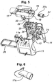
- the device comprises a base unit 11 containing an electric motor 12 and batteries 13 which drive the motor and associated control mechanisms which enable the speed of the motor to be varied.
- a base unit 11 containing an electric motor 12 and batteries 13 which drive the motor and associated control mechanisms which enable the speed of the motor to be varied.
- a head unit 16 Detachably attached to the base unit 11 is a head unit 16 having a mouthpiece 17 and an inlet 18 through which a user can breathe.
- the detachable attachability is obtained via slots and detents 11a in the base unit 11 into which flexible flaps 19 carrying lugs 20 in the head unit snap fit.
- the mouthpiece 17 and inlet 18 are linked by a conduit 21 in which there is a rotary valve 22.
- the motor is controlled by a control button 23 and drives the valve 22 via a separable motor shaft drive dog 24 and a drive shaft 25.
- the batteries in the base unit can be accessed through door 26 at the base of the base unit 11.
- a restrictor 27 incorporating a deformable tubular section 27a which allows it to be push-fitted into, and retained by, the inlet 18.
- a variety of different internal bore sizes can be used for the restrictor 27 to produce a variety of different background flow resistances; removing the restrictor 27 allows a change in the pulse amplitude with respect to background flow resistance.
- a disposable mouthpiece 17a may be push fitted over the mouth stub of the valve head to provide a better seal to the user's mouth and to improve hygiene through being washed or autoclaved at high temperature or discarded and replaced by another unit.
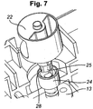
- the drive shaft 25 incorporates several narrow radial lands 28 projecting outwards while the drive dog 24, which is mounted on a motor shaft, is provided with a hollow tubular part with a similar number of inward facing lobes.
- the drive shaft 25 is devised to fit inside the drive dog when the valve head 16 is assembled onto the motor drive unit (base unit 11).
- the radial lands 28 of the drive shaft are dimensioned so that, as the motor rotates the drive dog, the internal lobes of the drive dog push against the side faces of the projecting lands of the drive shaft and impart radial motion.
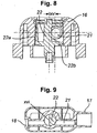
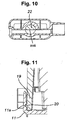
- the rotary valve 22 is shewn in greater detail in figures 8 to 10 . As can be seen the valve 22 is located at an offset (xv) from the conduit 21 main axis and has a solid closing face 22a and a cutaway face 22b.
- valve 22 when the rotary valve 22 is oriented in the shown position (xvi) it occludes the conduit 21 and thus provides a closure to the fluid flow.
- the valve rotates at approx 10Hz to 100Hz and thus provides a changing resistance to fluid flow with a maximum resistance occurring when the valve is in the shown fully closed position against which the user breathes.
- inhalation if the valve is in this position a partial vacuum or lowering of pressure will occur between the user and the valve, while during exhalation a positive or excess pressure will occur in the conduit between the user and the valve.
- intermediate valve rotation positions there will be essentially sinusoidal variations in developed pressures.
- valve 22 when the valve 22 is oriented in the shown position (xvii) it allows free flow of fluid in the conduit.
- the head 16 is attached to base unit 11 so that drive shaft 25 fits into and is driven by the drive dog 24 mounted on the motor shaft of the motor in the base unit.
- the lugs 20 snap fit into the slots thus holding the head unit in place.
- the speed of rotation of the motor can be varied during manufacture, which varies the frequency of the valve opening and closing and the flow of air to and from the user; this is set for optimal performance enhancement as dictated by experimental result, but is envisaged as between 5Hz and 100Hz and usually between 10Hz and 50Hz.
- the head 16 When the device is to be used by another user the head 16 can be removed and sterilised.
- each patient can have their own head unit so that several patients can have a personal head unit for their own use with one base unit used for all the patients.
- the portable device described has the following dimensions: height 10cm, breadth 75cm or 95 cm, thickness 44cm. Its weight is less than 200g. It is consequently susceptible of being comfortably held in one hand. Alternatively it can readily be mounted on a harness worn on the user's head.
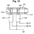
- the alternative embodiment illustrated in figure 12 has a mouthpiece 117 and an inlet 118 linked by a conduit 121. Across the conduit are two rotary valves 130, 140 in series. The valves are driven by motors 131, 141 respectively. The motor 131 is arranged to operate at constant speed while the motor 141 is arranged to operate at a constantly varying speed. The valves 131, 141 are constructed to occlude airflow for a very small arc of their rotation to arrive at an acceptable base flow occlusion. By this arrangement a considerable variation of occlusion rate is obtained.
- the alternative embodiment illustrated in figure 13 has a mouthpiece 217 with two associated inlets 218, 218a linked by parallel conduits 221, 221a. Across each conduit 221, 221a is a valve 230, 240 driven by motors 231, 241 respectively.
- the motor 231 is arranged to operate at constant speed while the motor 241 is arranged to operate at a constantly varying speed.
- the motors 131, 141, 231, 241 are conventional DC brush motors and gearboxes permit the valves to rotate at speeds considerably lower than the motors. Stepper motors could be employed instead.
- FIG 14 shows a detachable head unit conduit 100 having an inlet 101, a mouthpiece 102 and a valve 107. These correspond to the conduit 21, mouthpiece 17, inlet 18 and valve 22 described above with reference to figures 1 to 11 . Exterior to the conduit is an ambient sensor 103 of temperature and pressure. Inside the conduit 100, inboard of the mouthpiece 102, is a "user side" sensor 104 of temperature and pressure. Inside the conduit 100, just inboard of the inlet 101, is an inlet sensor 105 of temperature and pressure. The three sensors are connected to a data processor 106.
- Figure 15 illustrates a head unit such as that described above with reference to figure 14 but incorporating a feedback facility 108,
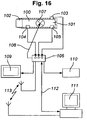
- Figure 16 illustrates a number of different ways in which output from the data processor 106 can be utilised.
- An on-board display or warning device 109 provides real time performance information to the user, his medical adviser or his trainer.
- An on-board data storage device 110 stores performance data for recordal and subsequent analysis.
- a remote data storage, processing, viewing management and control system 111 is associated with the data processor 106 either via cable 112 or wireless (radio, infra-red, blue tooth) link 113.
- the sensors 103, 104, and 105 and the data processor 106 are actually mounted in the base unit 11 and the sensors 104 and 105 protrude into the conduit 100 when the head unit 16 is mounted to the base.
- FIGs 17a, 17b, 17c illustrate schematically valve plugs with different degrees of “cut-away”.
- FIG 17a most of the valve is “cut away” and the axis of rotation of the plug 300 lies within the boundaries of the conduit 301.
- This construction is produced by having a base to the plug, not shewn, disposed beneath the conduit and associated with a drive shaft. Its effect is to produce a large valve opening time in relation to closed time, per revolution.
- the plug axis is tangential to the conduit boundary, approximately half the cylinder forming the valve is “cut away” and valve open and closed times per revolution are approximately equal.
- the plug axis is outside the conduit and less than half the cylinder forming the valve is "cut away”. In this case during each revolution the valve is closed for longer than it is open.
- Figure 18 compares the effects of a face which is somewhat concave or somewhat convex compared to one which is planar.
- the planar face valve defines a flow variation which is substantially sinusoidal.
- a concave face generates a shallower rate of area presentation while a concave face will cause an earlier start to the cut-off and a gentler rate of opening near to maximum.
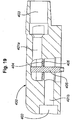
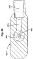
- FIG. 19 Another embodiment of the head of the device, a disc valve version, is illustrated in figures 19 and 20 .
- the head 400 defines a conduit in two parts 401a, 401b having an inlet 402 and a mouthpiece 403. The axes of the two parts of the conduit are offset and parallel. Between them is sited a disc valve 404 mounted on a drive shaft 405 and a co-operating valve base plate 406. As shewn the valve 404 and the base plate 406 are foraminous. However a variety of forms of perforation of the valve 404 and the plate 406 are possible. Where a slow enough motor or minimal or nil gearing are possible in the production of effective breathing checks, the disc and the plate may each be simply cut away to provide one check per revolution. Different shapes of the cut away and the holes (or slots) will vary the airflow wave form. Moreover, an irregular spacing of foramens around the disc provides a degree of randomness to the intermittence of the airflow cycle.
- the device head may be arranged so that discs can be interchangeable.
- Alternative embodiments of the invention incorporate an adjustable speed control. In one of these this adjustment is arranged for control by the user; in another, once initiated it is arranged for periodic speed variation and in another for random speed variation. These facilities are particularly valuable in training athletes and animals used in sport.
- the sensors 103, 104, 105 may also detect relative humidity.
- the power to drive the motor is from a battery incorporated in the base of the device, which may be rechargeable. Mains power may alternatively be employed. In another alternative a power storage unit is employed whence the electricity is derived by turning a handle manually.
Landscapes
- Health & Medical Sciences (AREA)
- General Health & Medical Sciences (AREA)
- Life Sciences & Earth Sciences (AREA)
- Engineering & Computer Science (AREA)
- Pulmonology (AREA)
- Physical Education & Sports Medicine (AREA)
- Veterinary Medicine (AREA)
- Heart & Thoracic Surgery (AREA)
- Animal Behavior & Ethology (AREA)
- Biomedical Technology (AREA)
- Public Health (AREA)
- Anesthesiology (AREA)
- Emergency Medicine (AREA)
- Hematology (AREA)
- Biophysics (AREA)
- Orthopedic Medicine & Surgery (AREA)
- Multimedia (AREA)
- Human Computer Interaction (AREA)
- Physics & Mathematics (AREA)
- Molecular Biology (AREA)
- Surgery (AREA)
- Medical Informatics (AREA)
- Pathology (AREA)
- Physiology (AREA)
- Percussion Or Vibration Massage (AREA)
Claims (18)
- Dispositif de respiration comprenant :une unité de base (11) ;une unité de tête (16) attachable de manière amovible à l'unité de base (11) ;un conduit (21) dans l'unité de tête (16) à travers lequel un utilisateur peut respirer ; et
caractérisé par :un moteur électrique (12) contenu dans l'unité de base (11) ;une valve (22) montée dans le conduit (21) associable par commande avec le moteur (12) et disposée pour interrompre l'écoulement d'air le long du conduit. - Dispositif de respiration selon la revendication 1 et ayant un embout (17, 17a) qui peut s'ajuster sur la bouche et/ou le nez d'un utilisateur de sorte qu'un utilisateur respire à travers l'embout.
- Dispositif selon la revendication 1 ou 2 et dans lequel l'embout (17, 17a) est détachable.
- Dispositif de respiration selon l'une quelconque des revendications précédentes et ayant une entrée d'air (18) au conduit (21) et un limitateur (27) dans l'entrée d'air (18) pour limiter l'écoulement d'air.
- Dispositif de respiration selon la revendication 4 et dans lequel le limitateur (27) est ajustable.
- Dispositif de respiration selon l'une quelconque des revendications précédentes et dans lequel la valve (22) est une valve rotative.
- Dispositif de respiration selon la revendication 6 dans lequel le moteur a un doigt d'entraînement (24) engageable avec un mécanisme de commande (25) à la valve (22).
- Dispositif de respiration selon la revendication 7 et dans lequel la valve rotative (22) comprend :l'unité de tête (16) contenant le conduit (21) avec un axe central ;un bouchon ayant une face de scellement coopérant avec un siège de valve dans ladite unité de tête (16) dans la position fermée pour bloquer le conduit (21), et où le mécanisme de commande comprend un arbre de support disposé pour porter ledit bouchon et être rotatif sur un axe qui est normal à l'axe et espacé à ce même axe dudit siège de valve et situé à l'extérieur du conduit (21) de sorte que la rotation dudit arbre (25) déplace ledit bouchon par rapport à ladite unité de tête (16).
- Dispositif de respiration selon la revendication 8 et dans lequel la valve (22) comprend une plaque poreuse et au moins un disque poreux associé avec la plaque de sorte que, à mesure qu'au moins le disque tourne relativement à la plaque, les pores dans le disque et la plaque sont périodiquement coïncidents de manière à former un passage d'écoulement d'air continu.
- Dispositif de respiration selon l'une quelconque des revendications 1 à 9 et incorporant une batterie.
- Dispositif de respiration selon la revendication 10 et dans lequel la batterie est rechargeable.
- Dispositif de respiration selon la revendication 11 et incorporant des moyens pour charger manuellement la batterie.
- Dispositif de respiration selon l'une quelconque des revendications précédentes et dans lequel l'unité de tête incorpore des capteurs de suivi des données et de réunion des données (103, 104, 105).
- Dispositif de respiration selon la revendication 13 et ayant un écran d'affichage (109) pour afficher les données obtenues.
- Dispositif de respiration selon la revendication 13 ou 14 et ayant des moyens (110, 111) pour stocker les données obtenues électroniquement.
- Dispositif de respiration selon l'une quelconque des revendications précédentes et ayant une pluralité de valves (130, 140).
- Dispositif de respiration selon la revendication 16 et dans lequel une des valves (130, 140) est disposée pour être commandée à une vitesse constante et une autre à une vitesse variable.
- Dispositif selon l'une quelconque des revendications précédentes et ayant des dimensions inférieures ou égales à 10 cm par 8 cm par 4 cm.
Applications Claiming Priority (1)
| Application Number | Priority Date | Filing Date | Title |
|---|---|---|---|
| GB0617349A GB2441583A (en) | 2006-09-05 | 2006-09-05 | Breathing device |
Publications (2)
| Publication Number | Publication Date |
|---|---|
| EP1897576A1 EP1897576A1 (fr) | 2008-03-12 |
| EP1897576B1 true EP1897576B1 (fr) | 2017-05-17 |
Family
ID=37137268
Family Applications (1)
| Application Number | Title | Priority Date | Filing Date |
|---|---|---|---|
| EP07115407.4A Active EP1897576B1 (fr) | 2006-09-05 | 2007-08-31 | Dispositif respiratoire portable |
Country Status (3)
| Country | Link |
|---|---|
| US (1) | US8360061B2 (fr) |
| EP (1) | EP1897576B1 (fr) |
| GB (1) | GB2441583A (fr) |
Families Citing this family (49)
| Publication number | Priority date | Publication date | Assignee | Title |
|---|---|---|---|---|
| US20090247850A1 (en) * | 2008-03-28 | 2009-10-01 | Nellcor Puritan Bennett Llc | Manually Powered Oximeter |
| US8251876B2 (en) | 2008-04-22 | 2012-08-28 | Hill-Rom Services, Inc. | Breathing exercise apparatus |
| US8539951B1 (en) | 2008-05-27 | 2013-09-24 | Trudell Medical International | Oscillating positive respiratory pressure device |
| GB0811981D0 (en) * | 2008-07-01 | 2008-07-30 | Hab Internat Ltd | Respiratory muscle training device |
| US8327849B2 (en) | 2008-10-28 | 2012-12-11 | Trudell Medical International | Oscillating positive expiratory pressure device |
| US8821409B2 (en) * | 2008-12-23 | 2014-09-02 | The United States Of America As Represented By The Secretary Of The Department Of Health And Human Services, Centers For Disease Control And Prevention | Lung aerosol collection device |
| US8485179B1 (en) | 2009-02-23 | 2013-07-16 | Trudell Medical International | Oscillating positive expiratory pressure device |
| US9149589B2 (en) | 2009-02-23 | 2015-10-06 | Trudell Medical International | Method and device for performing orientation dependent oscillating positive expiratory pressure therapy |
| CN101822894B (zh) * | 2009-09-03 | 2011-07-20 | 盐城卫生职业技术学院 | 一种呼吸训练系统 |
| US9554739B2 (en) | 2009-09-29 | 2017-01-31 | Covidien Lp | Smart cable for coupling a medical sensor to an electronic patient monitor |
| US9078610B2 (en) * | 2010-02-22 | 2015-07-14 | Covidien Lp | Motion energy harvesting with wireless sensors |
| WO2012112562A2 (fr) * | 2011-02-15 | 2012-08-23 | Gur Ory | Soupapes rotatives à orifice variable pour la régulation d'un écoulement de gaz |
| CN102678957A (zh) * | 2011-03-17 | 2012-09-19 | 德昌电机(深圳)有限公司 | 医疗用流体控制装置 |
| US9358417B2 (en) * | 2011-06-06 | 2016-06-07 | Trudell Medical International | Oscillating positive expiratory pressure device |
| US9180271B2 (en) | 2012-03-05 | 2015-11-10 | Hill-Rom Services Pte. Ltd. | Respiratory therapy device having standard and oscillatory PEP with nebulizer |
| CN107596527B (zh) * | 2012-04-27 | 2020-12-29 | 费雪派克医疗保健有限公司 | 用于呼吸增湿系统的可用性特征 |
| US9517315B2 (en) * | 2012-11-30 | 2016-12-13 | Trudell Medical International | Oscillating positive expiratory pressure device |
| GB2512047B (en) * | 2013-03-15 | 2015-07-15 | Univ Sheffield Hallam | Positive Expiratory Pressure Device With Electronic Monitoring |
| WO2014203115A1 (fr) * | 2013-06-19 | 2014-12-24 | Koninklijke Philips N.V. | Dispositif d'assistance à la toux |
| CN105324159B (zh) * | 2013-06-19 | 2017-12-19 | 皇家飞利浦有限公司 | 用于辅助咳嗽的装置 |
| EP3019137B1 (fr) | 2013-07-12 | 2019-02-06 | Trudell Medical International | Dispositif de simulation de toux soufflée ("huff cough") |
| US9849257B2 (en) | 2013-08-22 | 2017-12-26 | Trudell Medical International | Oscillating positive respiratory pressure device |
| CN108704213B (zh) | 2013-09-13 | 2021-06-22 | 费雪派克医疗保健有限公司 | 用于加湿系统的连接 |
| US9486187B2 (en) | 2013-09-26 | 2016-11-08 | Covidien Lp | Wind up deployment mechanisms for surgical instruments |
| GB201400188D0 (en) * | 2014-01-07 | 2014-02-26 | Smiths Medical Int Ltd | Respiratory therapy apparatus |
| US10363383B2 (en) | 2014-02-07 | 2019-07-30 | Trudell Medical International | Pressure indicator for an oscillating positive expiratory pressure device |
| GB201407571D0 (en) * | 2014-04-30 | 2014-06-11 | Smiths Medical Int Ltd | Respiratory therapy devices |
| CN106535971B (zh) | 2014-06-03 | 2020-12-04 | 费雪派克医疗保健有限公司 | 用于呼吸治疗系统的流动混合器 |
| RU2582762C1 (ru) * | 2014-10-14 | 2016-04-27 | Федеральное государственное бюджетное учреждение "Дальневосточный научный центр физиологии и патологии дыхания" Сибирского отделения Российской академии медицинских наук (ФГБУ "ДНЦ ФПД" СО РАМН) | Способ немедикаментозной реабилитации детей с бронхиальной астмой |
| JP6644778B2 (ja) | 2014-10-31 | 2020-02-12 | コーニンクレッカ フィリップス エヌ ヴェKoninklijke Philips N.V. | 咳嗽流の増大の間の圧力制御 |
| TWD169846S (zh) * | 2014-12-12 | 2015-08-11 | 李文欽 | 噴霧器(二) |
| US10881817B2 (en) | 2014-12-26 | 2021-01-05 | Koninklijke Philips N.V. | Secretion loosening and cough segmenting therapy |
| US10004872B1 (en) | 2015-03-06 | 2018-06-26 | D R Burton Healthcare, Llc | Positive expiratory pressure device having an oscillating valve |
| US10905836B2 (en) | 2015-04-02 | 2021-02-02 | Hill-Rom Services Pte. Ltd. | Manifold for respiratory device |
| JP7016795B2 (ja) | 2015-07-30 | 2022-02-07 | トルーデル メディカル インターナショナル | 呼吸筋トレーニングと呼気陽圧振動の複合装置 |
| USD780906S1 (en) | 2015-09-02 | 2017-03-07 | Trudell Medical International | Respiratory treatment device |
| USD778429S1 (en) | 2015-09-02 | 2017-02-07 | Trudell Medical International | Respiratory treatment device |
| ES2608969B1 (es) * | 2015-10-08 | 2017-09-28 | Oscar MEMBRADO LOPE | Dispositivo de fisioterapia respiratoria |
| ES2855373T3 (es) | 2015-12-04 | 2021-09-23 | Trudell Medical Int | Dispositivo de simulación de tos por espiración forzada |
| WO2017187116A1 (fr) * | 2016-04-27 | 2017-11-02 | Smiths Medical International Limited | Appareil de thérapie respiratoire |
| WO2018011358A1 (fr) * | 2016-07-13 | 2018-01-18 | Aerofit.Dk Aps | Dispositif et système respiratoire pour exercice et analyse de la respiration d'un sujet |
| WO2018203188A1 (fr) | 2017-05-03 | 2018-11-08 | Trudell Medical International | Thérapie par pression expiratoire positive oscillante combinée et dispositif de simulation de toux soufflée ("huff cough") |
| CA3086890A1 (fr) * | 2018-01-04 | 2019-07-11 | Trudell Medical International | Dispositif intelligent a pression expiratoire positive oscillante |
| US10953278B2 (en) | 2018-02-02 | 2021-03-23 | Trudell Medical International | Oscillating positive expiratory pressure device |
| AU2020340604A1 (en) * | 2019-09-03 | 2022-03-17 | Trudell Medical International Inc. | Medical device with energy harvesting system |
| CN111298384B (zh) * | 2020-02-25 | 2021-06-22 | 黄淮学院 | 一种声乐演唱肺活量练习装置 |
| US11420007B2 (en) * | 2020-08-05 | 2022-08-23 | Effortless Oxygen, Llc | Flow triggered gas delivery |
| US11318276B2 (en) | 2020-08-05 | 2022-05-03 | Effortless Oxygen, Llc | Flow triggered gas delivery |
| CN113476804B (zh) * | 2021-07-12 | 2022-09-20 | 广西力拓医疗科技有限公司 | 一种呼吸科患者肺功能康复训练系统 |
Family Cites Families (16)
| Publication number | Priority date | Publication date | Assignee | Title |
|---|---|---|---|---|
| US1459478A (en) * | 1919-12-04 | 1923-06-19 | William A Page | Inhaling tube |
| GB2196858A (en) | 1986-09-30 | 1988-05-11 | Roland Richard Gibson | Respiratory apparatus |
| US5438980A (en) * | 1993-01-12 | 1995-08-08 | Puritan-Bennett Corporation | Inhalation/exhalation respiratory phase detection circuit |
| US6083141A (en) | 1995-02-10 | 2000-07-04 | Hougen; Everett D. | Portable respiratory exercise apparatus and method for using the same |
| FR2744922B1 (fr) | 1996-02-20 | 1998-05-07 | Reynes Philippe | Appareil fluidificateur du mucus bronchique pathologique |
| US6058932A (en) * | 1997-04-21 | 2000-05-09 | Hughes; Arthur R. | Acoustic transceiver respiratory therapy apparatus |
| AUPP240198A0 (en) * | 1998-03-17 | 1998-04-09 | Resmed Limited | An apparatus for supplying breathable gas |
| US6708690B1 (en) * | 1999-09-03 | 2004-03-23 | Respironics, Inc. | Apparatus and method for providing high frequency variable pressure to a patient |
| US6581596B1 (en) | 1999-09-24 | 2003-06-24 | Respironics, Inc. | Apparatus and method of providing high frequency variable pressure to a patient |
| US6776159B2 (en) * | 1999-11-24 | 2004-08-17 | Dhd Healthcare Corporation | Positive expiratory pressure device with bypass |
| US7059324B2 (en) * | 1999-11-24 | 2006-06-13 | Smiths Medical Asd, Inc. | Positive expiratory pressure device with bypass |
| US6581598B1 (en) | 1999-11-24 | 2003-06-24 | Dhd Healthcare Corporation | Positive expiratory pressure device |
| GB0205760D0 (en) | 2002-03-12 | 2002-04-24 | Southbank University Entpr Ltd | Vibrationary exercise apparatus |
| GB0316349D0 (en) | 2003-07-11 | 2003-08-13 | Micro Medical Ltd | Apparatus for determining respiratory muscle endurance of a person |
| GB0507547D0 (en) | 2005-04-14 | 2005-05-18 | Ramer Ltd | Exercise device and methods of exercising |
| US20060279085A1 (en) * | 2005-06-08 | 2006-12-14 | Kenneth Lee | Portable electrical device with dynamic battery recharging |
-
2006
- 2006-09-05 GB GB0617349A patent/GB2441583A/en not_active Withdrawn
-
2007
- 2007-08-28 US US11/845,916 patent/US8360061B2/en active Active
- 2007-08-31 EP EP07115407.4A patent/EP1897576B1/fr active Active
Also Published As
| Publication number | Publication date |
|---|---|
| EP1897576A1 (fr) | 2008-03-12 |
| US20080053456A1 (en) | 2008-03-06 |
| GB0617349D0 (en) | 2006-10-11 |
| GB2441583A (en) | 2008-03-12 |
| US8360061B2 (en) | 2013-01-29 |
Similar Documents
| Publication | Publication Date | Title |
|---|---|---|
| EP1897576B1 (fr) | Dispositif respiratoire portable | |
| EP1897597B1 (fr) | Dispositif respiratoire interrompu de manière aléatoire | |
| US20200306468A1 (en) | Oscillating positive respiratory pressure device | |
| CA2212642C (fr) | Appareil respiratoire individuel et portable | |
| US20210001067A1 (en) | Positive exhalation pressure device | |
| AU2001235258B2 (en) | Dual-pressure blower for positive air pressure device | |
| US8257288B2 (en) | Chest compression apparatus having physiological sensor accessory | |
| US10639436B2 (en) | Device for manipulating respiratory air flow and use thereof | |
| US20170028160A1 (en) | Respiratory therapy devices | |
| US20110125068A1 (en) | Frequency Optimization for Chest Compression Apparatus | |
| US10702450B2 (en) | Chest compression devices, systems, and methods | |
| KR102212353B1 (ko) | 흉벽 진동 기능과 호흡근력 강화 기능이 융합된 호흡재활운동기기를 이용한 호흡 재활 운동 관리 시스템 | |
| TWI808498B (zh) | 肺復原裝置 | |
| EP1397994B1 (fr) | Appareil pour mesurer la force des muscles respiratoires d'une personne | |
| GB2530397A (en) | Respiratory therapy devices | |
| WO2009152252A2 (fr) | Appareil de compression de poitrine pourvu d'un accessoire à capteurs physiologiques |
Legal Events
| Date | Code | Title | Description |
|---|---|---|---|
| PUAI | Public reference made under article 153(3) epc to a published international application that has entered the european phase |
Free format text: ORIGINAL CODE: 0009012 |
|
| AK | Designated contracting states |
Kind code of ref document: A1 Designated state(s): AT BE BG CH CY CZ DE DK EE ES FI FR GB GR HU IE IS IT LI LT LU LV MC MT NL PL PT RO SE SI SK TR |
|
| AX | Request for extension of the european patent |
Extension state: AL BA HR MK YU |
|
| 17P | Request for examination filed |
Effective date: 20080319 |
|
| 17Q | First examination report despatched |
Effective date: 20080502 |
|
| AKX | Designation fees paid |
Designated state(s): DE ES FR GB IT |
|
| RAP1 | Party data changed (applicant data changed or rights of an application transferred) |
Owner name: BROWN, ROGER LESLIE Owner name: SUMNERS, DAVID PAUL |
|
| RIN1 | Information on inventor provided before grant (corrected) |
Inventor name: SUMNERS, DAVID PAUL Inventor name: BROWN, ROGER LESLIE |
|
| RAP1 | Party data changed (applicant data changed or rights of an application transferred) |
Owner name: HIGH TECH HEALTH LIMITED |
|
| RIN1 | Information on inventor provided before grant (corrected) |
Inventor name: HIGH TECH HEALTH LIMITED |
|
| RAP1 | Party data changed (applicant data changed or rights of an application transferred) |
Owner name: ACTEGY LIMITED |
|
| RIN1 | Information on inventor provided before grant (corrected) |
Inventor name: ACTEGY LIMITED |
|
| GRAP | Despatch of communication of intention to grant a patent |
Free format text: ORIGINAL CODE: EPIDOSNIGR1 |
|
| RIN1 | Information on inventor provided before grant (corrected) |
Inventor name: SUMNERS, DAVID PAUL Inventor name: BROWN, ROGER LESLIE |
|
| INTG | Intention to grant announced |
Effective date: 20170104 |
|
| GRAS | Grant fee paid |
Free format text: ORIGINAL CODE: EPIDOSNIGR3 |
|
| GRAA | (expected) grant |
Free format text: ORIGINAL CODE: 0009210 |
|
| AK | Designated contracting states |
Kind code of ref document: B1 Designated state(s): DE ES FR GB IT |
|
| REG | Reference to a national code |
Ref country code: GB Ref legal event code: FG4D |
|
| REG | Reference to a national code |
Ref country code: DE Ref legal event code: R096 Ref document number: 602007051012 Country of ref document: DE |
|
| REG | Reference to a national code |
Ref country code: FR Ref legal event code: PLFP Year of fee payment: 11 |
|
| PG25 | Lapsed in a contracting state [announced via postgrant information from national office to epo] |
Ref country code: ES Free format text: LAPSE BECAUSE OF FAILURE TO SUBMIT A TRANSLATION OF THE DESCRIPTION OR TO PAY THE FEE WITHIN THE PRESCRIBED TIME-LIMIT Effective date: 20170517 |
|
| REG | Reference to a national code |
Ref country code: DE Ref legal event code: R097 Ref document number: 602007051012 Country of ref document: DE |
|
| PG25 | Lapsed in a contracting state [announced via postgrant information from national office to epo] |
Ref country code: IT Free format text: LAPSE BECAUSE OF FAILURE TO SUBMIT A TRANSLATION OF THE DESCRIPTION OR TO PAY THE FEE WITHIN THE PRESCRIBED TIME-LIMIT Effective date: 20170517 |
|
| PLBE | No opposition filed within time limit |
Free format text: ORIGINAL CODE: 0009261 |
|
| STAA | Information on the status of an ep patent application or granted ep patent |
Free format text: STATUS: NO OPPOSITION FILED WITHIN TIME LIMIT |
|
| 26N | No opposition filed |
Effective date: 20180220 |
|
| REG | Reference to a national code |
Ref country code: FR Ref legal event code: PLFP Year of fee payment: 12 |
|
| PGFP | Annual fee paid to national office [announced via postgrant information from national office to epo] |
Ref country code: GB Payment date: 20230717 Year of fee payment: 17 |
|
| PGFP | Annual fee paid to national office [announced via postgrant information from national office to epo] |
Ref country code: FR Payment date: 20230814 Year of fee payment: 17 Ref country code: DE Payment date: 20230818 Year of fee payment: 17 |