EP1895902B1 - Appareil de surveillance de perfusion cerebrale - Google Patents
Appareil de surveillance de perfusion cerebrale Download PDFInfo
- Publication number
- EP1895902B1 EP1895902B1 EP06701857A EP06701857A EP1895902B1 EP 1895902 B1 EP1895902 B1 EP 1895902B1 EP 06701857 A EP06701857 A EP 06701857A EP 06701857 A EP06701857 A EP 06701857A EP 1895902 B1 EP1895902 B1 EP 1895902B1
- Authority
- EP
- European Patent Office
- Prior art keywords
- signal
- ppg
- ipg
- blood flow
- maximum
- Prior art date
- Legal status (The legal status is an assumption and is not a legal conclusion. Google has not performed a legal analysis and makes no representation as to the accuracy of the status listed.)
- Not-in-force
Links
- 230000003788 cerebral perfusion Effects 0.000 title 1
- 230000000747 cardiac effect Effects 0.000 claims description 112
- 230000003727 cerebral blood flow Effects 0.000 claims description 107
- 238000013186 photoplethysmography Methods 0.000 claims description 107
- 238000000034 method Methods 0.000 claims description 51
- 230000029058 respiratory gaseous exchange Effects 0.000 claims description 15
- 238000009499 grossing Methods 0.000 claims description 14
- 238000012545 processing Methods 0.000 claims description 8
- 210000003128 head Anatomy 0.000 description 35
- 230000017531 blood circulation Effects 0.000 description 33
- 210000004556 brain Anatomy 0.000 description 27
- 210000001367 artery Anatomy 0.000 description 19
- CURLTUGMZLYLDI-UHFFFAOYSA-N Carbon dioxide Chemical compound O=C=O CURLTUGMZLYLDI-UHFFFAOYSA-N 0.000 description 16
- 210000004369 blood Anatomy 0.000 description 12
- 239000008280 blood Substances 0.000 description 12
- 230000007423 decrease Effects 0.000 description 10
- 229910002092 carbon dioxide Inorganic materials 0.000 description 8
- 239000001569 carbon dioxide Substances 0.000 description 8
- 230000000694 effects Effects 0.000 description 8
- 230000006870 function Effects 0.000 description 8
- 238000012360 testing method Methods 0.000 description 7
- 230000036772 blood pressure Effects 0.000 description 6
- 230000001143 conditioned effect Effects 0.000 description 5
- 230000002596 correlated effect Effects 0.000 description 5
- 230000003205 diastolic effect Effects 0.000 description 5
- 238000012544 monitoring process Methods 0.000 description 5
- 230000002829 reductive effect Effects 0.000 description 5
- 238000012935 Averaging Methods 0.000 description 4
- 210000004958 brain cell Anatomy 0.000 description 4
- 230000006378 damage Effects 0.000 description 4
- 238000013171 endarterectomy Methods 0.000 description 4
- 230000002093 peripheral effect Effects 0.000 description 4
- 210000004761 scalp Anatomy 0.000 description 4
- 208000027418 Wounds and injury Diseases 0.000 description 3
- 208000014674 injury Diseases 0.000 description 3
- 238000001356 surgical procedure Methods 0.000 description 3
- 238000002604 ultrasonography Methods 0.000 description 3
- QVGXLLKOCUKJST-UHFFFAOYSA-N atomic oxygen Chemical compound [O] QVGXLLKOCUKJST-UHFFFAOYSA-N 0.000 description 2
- 210000001715 carotid artery Anatomy 0.000 description 2
- 230000000875 corresponding effect Effects 0.000 description 2
- 210000005069 ears Anatomy 0.000 description 2
- 238000013213 extrapolation Methods 0.000 description 2
- 238000005259 measurement Methods 0.000 description 2
- 238000010606 normalization Methods 0.000 description 2
- 229910052760 oxygen Inorganic materials 0.000 description 2
- 239000001301 oxygen Substances 0.000 description 2
- 230000002035 prolonged effect Effects 0.000 description 2
- 238000011160 research Methods 0.000 description 2
- 239000000523 sample Substances 0.000 description 2
- 210000002385 vertebral artery Anatomy 0.000 description 2
- 208000032843 Hemorrhage Diseases 0.000 description 1
- 208000032456 Hemorrhagic Shock Diseases 0.000 description 1
- 206010036590 Premature baby Diseases 0.000 description 1
- 206010049771 Shock haemorrhagic Diseases 0.000 description 1
- 238000002583 angiography Methods 0.000 description 1
- 230000037007 arousal Effects 0.000 description 1
- 230000006793 arrhythmia Effects 0.000 description 1
- 206010003119 arrhythmia Diseases 0.000 description 1
- 230000008321 arterial blood flow Effects 0.000 description 1
- 230000000740 bleeding effect Effects 0.000 description 1
- 230000000903 blocking effect Effects 0.000 description 1
- 230000003925 brain function Effects 0.000 description 1
- 210000005013 brain tissue Anatomy 0.000 description 1
- 244000309466 calf Species 0.000 description 1
- 210000001168 carotid artery common Anatomy 0.000 description 1
- 210000000269 carotid artery external Anatomy 0.000 description 1
- 210000004004 carotid artery internal Anatomy 0.000 description 1
- 208000006170 carotid stenosis Diseases 0.000 description 1
- 210000004027 cell Anatomy 0.000 description 1
- 230000002490 cerebral effect Effects 0.000 description 1
- 230000001149 cognitive effect Effects 0.000 description 1
- 230000036992 cognitive tasks Effects 0.000 description 1
- 230000001276 controlling effect Effects 0.000 description 1
- 230000003247 decreasing effect Effects 0.000 description 1
- 239000003814 drug Substances 0.000 description 1
- 229940079593 drug Drugs 0.000 description 1
- 210000001061 forehead Anatomy 0.000 description 1
- 239000007789 gas Substances 0.000 description 1
- 238000002347 injection Methods 0.000 description 1
- 239000007924 injection Substances 0.000 description 1
- 230000001788 irregular Effects 0.000 description 1
- 230000002427 irreversible effect Effects 0.000 description 1
- 238000002595 magnetic resonance imaging Methods 0.000 description 1
- 238000013178 mathematical model Methods 0.000 description 1
- 230000003340 mental effect Effects 0.000 description 1
- 230000006996 mental state Effects 0.000 description 1
- 208000010125 myocardial infarction Diseases 0.000 description 1
- 230000009251 neurologic dysfunction Effects 0.000 description 1
- 208000015015 neurological dysfunction Diseases 0.000 description 1
- 230000007658 neurological function Effects 0.000 description 1
- 230000003287 optical effect Effects 0.000 description 1
- 230000036961 partial effect Effects 0.000 description 1
- 210000005259 peripheral blood Anatomy 0.000 description 1
- 239000011886 peripheral blood Substances 0.000 description 1
- 238000002600 positron emission tomography Methods 0.000 description 1
- 230000005855 radiation Effects 0.000 description 1
- 230000002285 radioactive effect Effects 0.000 description 1
- 239000012857 radioactive material Substances 0.000 description 1
- 230000004895 regional blood flow Effects 0.000 description 1
- 230000002441 reversible effect Effects 0.000 description 1
- 230000009528 severe injury Effects 0.000 description 1
- 230000001568 sexual effect Effects 0.000 description 1
- 210000003625 skull Anatomy 0.000 description 1
- 239000007787 solid Substances 0.000 description 1
- 230000002123 temporal effect Effects 0.000 description 1
- 238000012549 training Methods 0.000 description 1
- 230000000472 traumatic effect Effects 0.000 description 1
- 229910052724 xenon Inorganic materials 0.000 description 1
- FHNFHKCVQCLJFQ-UHFFFAOYSA-N xenon atom Chemical compound [Xe] FHNFHKCVQCLJFQ-UHFFFAOYSA-N 0.000 description 1
Images


Classifications
-
- A—HUMAN NECESSITIES
- A61—MEDICAL OR VETERINARY SCIENCE; HYGIENE
- A61B—DIAGNOSIS; SURGERY; IDENTIFICATION
- A61B5/00—Measuring for diagnostic purposes; Identification of persons
- A61B5/05—Detecting, measuring or recording for diagnosis by means of electric currents or magnetic fields; Measuring using microwaves or radio waves
- A61B5/053—Measuring electrical impedance or conductance of a portion of the body
- A61B5/0535—Impedance plethysmography
-
- A—HUMAN NECESSITIES
- A61—MEDICAL OR VETERINARY SCIENCE; HYGIENE
- A61B—DIAGNOSIS; SURGERY; IDENTIFICATION
- A61B5/00—Measuring for diagnostic purposes; Identification of persons
- A61B5/02—Detecting, measuring or recording pulse, heart rate, blood pressure or blood flow; Combined pulse/heart-rate/blood pressure determination; Evaluating a cardiovascular condition not otherwise provided for, e.g. using combinations of techniques provided for in this group with electrocardiography or electroauscultation; Heart catheters for measuring blood pressure
- A61B5/026—Measuring blood flow
- A61B5/0261—Measuring blood flow using optical means, e.g. infrared light
-
- A—HUMAN NECESSITIES
- A61—MEDICAL OR VETERINARY SCIENCE; HYGIENE
- A61B—DIAGNOSIS; SURGERY; IDENTIFICATION
- A61B5/00—Measuring for diagnostic purposes; Identification of persons
- A61B5/40—Detecting, measuring or recording for evaluating the nervous system
- A61B5/4058—Detecting, measuring or recording for evaluating the nervous system for evaluating the central nervous system
- A61B5/4064—Evaluating the brain
-
- A—HUMAN NECESSITIES
- A61—MEDICAL OR VETERINARY SCIENCE; HYGIENE
- A61B—DIAGNOSIS; SURGERY; IDENTIFICATION
- A61B5/00—Measuring for diagnostic purposes; Identification of persons
- A61B5/72—Signal processing specially adapted for physiological signals or for diagnostic purposes
- A61B5/7235—Details of waveform analysis
- A61B5/7239—Details of waveform analysis using differentiation including higher order derivatives
Definitions
- the field of the invention relates to measuring blood flow in the head.
- a number of common situations may cause a decrease in the general blood flow to the brain, including arrhythmia, myocardial infarction, and traumatic hemorrhagic shock.
- a sudden increase in blood flow to the brain may also cause severe damage, and is especially likely to occur in newborn or premature babies, although such an increase may also occur in other patients with certain medical conditions, or during surgery.
- data regarding the quantity of blood flow in the brain, and the changes in flow rate may be important in evaluating the risk of injury to the brain tissue and the efficacy of treatment. The availability of such data may enable the timely performance of various medical procedures to increase, decrease, or stabilize the cerebral blood flow, and prevent permanent damage to the brain.
- Cerebral blood flow may also be inferred indirectly by monitoring neurological function, but since neurological dysfunction is often irreversible by the time it is detected, it is more desirable to detect changes in cerebral blood flow directly, while its effects on brain function are still reversible.
- TCD trans-cranial Doppler
- Doppler ultrasound may also be used to measure blood flow in the carotid arteries, providing an estimate of blood flow to the head, but not specifically to the brain, and not including blood flow to the head through the vertebral arteries. Blood flow through the vertebral arteries is difficult to measure by ultrasound because of their proximity to the vertebrae.
- US patent 6,832,113 to Belalcazar describes the use of either IPG or PPG to measure blood flow, for purposes of optimizing a cardiac pacemaker.
- US patent 6,169,914, to Hovland et al. describes the use of various types of sensors, including IPG and PPG, for monitoring female sexual arousal with a vaginal probe, and describes using different types of sensors in combination.
- An aspect of some embodiments of the invention relates to determining cerebral blood flow from IPG data, using the data only from selected cardiac cycles, and discarding the data from other cardiac cycles, according to characteristics of the IPG data and/or other data, for example EKG data.
- the IPG data is obtained from electrodes placed on the head or in ears, for example as described in any of the above mentioned related patent applications.
- the cerebral blood flow is determined from a combination of IPG data and PPG data, and characteristics of the IPG data, the PPG data, other data, or any combination of them, are used to select cardiac cycles from which the IPG and PPG data is used.
- the PPG data is obtained from PPG sensors placed on the head or in the ears, for example as described in any of the above mentioned related patent applications.
- these characteristics comprise the duration of the cardiac cycle, and data is used for cardiac cycles that have similar duration, while cardiac cycles with very different durations are discarded.
- the characteristics comprise a cross-correlation between the signal for each cardiac cycle and the following (or preceding) cardiac cycle, for the IPG signal and/or for the PPG signal. For example, data is used for a cardiac cycle only if the cross-correlation exceeds a threshold, for the IPG signal or for the PPG signal, or only if the cross-correlation exceeds a threshold for both the IPG and PPG signals.
- breathing artifacts are reduced, for example, by adjusting the data differently in each cardiac cycle, such that the data at a particular phase in the cardiac cycle, or an average of the data over a particular range of phases of the cardiac cycle, always has a fixed value.
- breathing artifacts are substantially removed from the IPG data and/or from the PPG data, for example the cerebral blood flow calculated from the IPG and PPG data varies by less than 10% as a function of phase of the breathing cycle, on average over many breathing cycles.
- the particular phase in the cardiac cycle is the diastolic phase, as indicated, for example, by the peak of the R-wave, or as indicated by a minimum in the IPG signal or the PPG signal.
- An aspect of some embodiments of the invention relates to using a ratio of a slope, optionally a maximum slope of the IPG signal to a slope, optionally a maximum slope of the PPG signal, as a measure of cerebral blood flow.
- This slope is believed to be strongly correlated with the blood inflow.
- the maximum slope used for both the IPG and PPG signals is the maximum slope of the leading edge, following the diastolic phase.
- the maximum slope used for one or both signals is the slope of maximum absolute value at the trailing edge, preceding the diastolic phase.
- the maximum slope is normalized, for example by dividing it by a measure of the amplitude of the signal for that cardiac cycle.
- the resulting measurement of cerebral blood flow is then smoothed by using an average over time.
- a running average over time is used, with a fixed time interval, for example a few seconds, or with a fixed number of cardiac cycles.
- the smoothing is done over a time interval that varies with time, adapting to characteristics of the signal.
- a method of estimating cerebral blood flow by analyzing IPG and PPG signals of the head comprising:
- finding the maximum or most negative slope comprises finding the maximum slope, for both the IPG and PPG signals, and finding a ratio comprises finding a ratio of the maximum slopes.
- the maximum slopes are maximums within a leading portion of the cardiac cycle.
- finding the maximum or most negative slope comprises finding the most negative slope, for both the IPG and PPG signals, and finding a ratio comprises finding a ratio of the most negative slopes.
- the most negative slopes are most negative within a trailing portion of the cardiac cycle.
- the maximum or most negative slope of at least one of the signals is normalized to a measure of the amplitude of said signal.
- the measure of the amplitude is the peak-to-peak amplitude of said signal over the cardiac cycle.
- the measure of the amplitude is an average value of said signal over the cardiac cycle.
- the PPG signal comes from a PPG sensor on the left side of the head. Additionally or alternatively, the PPG signal comes from a PPG sensor on the right side of the head.
- the PPG signal is an average of signals from a PPG sensor on the left side of the head and a PPG sensor on the right side of the head.
- a method of estimating time-varying cerebral blood flow comprising:
- performing data processing comprises discarding data of the IPG signal, the PPG signal, or both, for cardiac cycles which meet one or more criteria for discarding.
- the criteria comprise having a duration outside an expected range.
- the expected range has a maximum between 1.3 and 2 times an average duration of cardiac cycles.
- the criteria comprise one or both of the IPG signal and the PPG signal having a cross-correlation below a threshold, between that cardiac cycle and the following cardiac cycle.
- the criteria comprise one or both of the IPG signal and the PPG signal having a cross-correlation below a threshold, between that cardiac cycle and the preceding cardiac cycle.
- the threshold is between +0.5 and +0.8.
- performing data processing comprises reducing breathing artifacts in the IPG signal, the PPG signal, or both.
- calculating the cerebral blood flow indicator comprises using the method according to an exemplary embodiment of the invention.
- performing data processing comprises smoothing the cerebral blood flow indicator.
- smoothing comprises finding an average over a time interval.
- smoothing comprises using a time scale that is adjusted adaptively, depending on behavior of the cerebral blood flow indicator as a function of time.
- Fig. 1 shows a flowchart 100, outlining a method for finding cerebral blood flow (CBF) according to an exemplary embodiment of the invention.
- CBF cerebral blood flow
- raw IPG and PPG data of the head is acquired.
- the data is acquired, for example, using any of the methods described in any of the above mentioned related patent applications or the patents, and publications as referenced in the Background, or any other methods known in the art for acquiring IPG and PPG data of the head.
- combined sensors incorporating both electrodes for IPG and optical sensors for PPG, are used, or separate sensors are used.
- the IPG electrodes are designed to be of a size and shape, and are positioned on the head, so as to obtain IPG data that is relatively more sensitive to the impedance of the interior of the skull, and relatively less sensitive to the impedance of the scalp, as described in the above mentioned patent applications. Examples of raw IPG and PPG signals as a function of time are shown respectively in plots 202 and 204 of Figs. 2A and 2B .
- there is more than one PPG sensor for example, there are two PPG sensors, one on each side of the head.
- the two PPG sensors are located respectively on the left and right sides of the forehead.
- either the PPG signal from the left side of the head or the PPG signal from the right side of the head may be used, or an average of the two PPG signals may be used, possibly a weighted average.
- the raw IPG and/or PPG signals are optionally conditioned to reduce breathing artifacts. This is done, for example, by adjusting the signals so that the minimum value for each cardiac cycle has a constant value, set at zero in Figs. 2C and 2D . Methods of defining what constitutes a single cardiac cycle are described below, in connection with 106.
- the resulting conditioned IPG signal, shown in plot 206, and conditioned PPG signal, shown in plot 208, are nearly free of breathing artifacts.
- any remaining correlation of the IPG signal and/or the PPG signal to the breathing cycle optionally results in less than a 10% effect on the calculated cerebral blood flow.
- the values between minima are reduced by the average value or an interpolated value of the adjacent minima.
- "good" cardiac cycles are selected, and data from other cardiac cycles is discarded.
- one or more of three criteria are used for discarding data from some cardiac cycles.
- the first criterion concerns how much the duration of the cardiac cycle differs from an average duration.
- the second and third criteria concern how much the form of the signal for a given cardiac cycle differs from the form of the signal for the following (or preceding) cardiac cycle, for the IPG signal and the PPG signal respectively.
- Data from cardiac cycles which satisfy one or more of these criteria is likely to have a high noise level which distorts the signals, or may correspond to an irregular heartbeat which does not provide a typical value for cerebral blood flow.
- the inventors have found that discarding data for cardiac cycles which satisfy any one of these three criteria is particularly useful for determining an accurate measure of cerebral blood flow.
- data is discarded only if the cardiac cycle satisfies two of these criteria, or all three criteria.
- only one of these three criteria is used as a criterion to discard data.
- only two of the criteria are used, and the data is discarded if either of the two criteria is satisfied.
- all three criteria are used, and the data is discarded if any of the criteria are satisfied.
- Other criteria for determining if the data for a particular cardiac cycle should be discarded will occur to a person of skill in the art.
- the duration of the cardiac cycle is determined, for example, using EKG data, and defined as the time from the peak of one R-wave to the peak of the next R-wave.
- the peak optionally must meet certain criteria. For example, the peak falls between 0.3 seconds and 1.5 seconds of the peak of the previous R-wave. If there is more than one local peak within this time interval, the peak of the R-wave is optionally found by finding the peak which most resembles the expected amplitude and time interval for the peak of an R-wave.
- the expected amplitude and time interval are based, for example, on the amplitude and time interval for the previous peak of an R-wave, or on a running average of past values.
- IPG data and/or PPG data is used instead of or in addition to using the peak of the R-wave to define the duration of the cardiac cycles.
- the duration of a cardiac cycle is defined as the time from one local minimum (or maximum) to the next local minimum (or maximum) in the IPG and/or the PPG signal, or as the time from one local maximum (or minimum) in slope of the signal to the next local maximum (or minimum) in slope.
- the local minimum or maximum in the IPG or PPG signal, or in the slope of the IPG or PPG signal must meet certain criteria, for example criteria similar or identical to the criteria described above for using the peak of the R-wave.
- data is discarded for those cardiac cycles that have a duration outside an expected range.
- the maximum of the expected range is between 1.3 and 2 times an average duration of a cardiac cycle.
- the maximum is 1.65 times the average duration.
- the maximum of the expected range is less than 1.3 times the average duration.
- the minimum of the expected range is less than 0.7 times the average duration.
- the minimum of the expected range is more than 0.7 times the average duration.
- there is no explicit minimum to the range although there may be a minimum duration for any cardiac cycle, due to the way that cardiac cycles are defined, as described above.
- the "average duration of a cardiac cycle” described above is optionally the median or the mode of the durations of the cardiac cycles.
- a potential advantage of using the median or the mode, rather than the mean, is that the median and the mode are relatively insensitive to the values of outliers that may represent noise in the data rather than real durations of cardiac cycles.
- the "average duration of a cardiac cycle” is the mean of the durations of cardiac cycles.
- the "average duration of a cardiac cycle” is a running average, for example over several cardiac cycles, or over several tens of cardiac cycles. Using a running average for the average duration of a cardiac cycle has the potential advantage of adjusting the average duration to real changes in the patient's pulse rate, due to physiological changes over time.
- a fixed value is used in place of the "average duration of a cardiac cycle," optionally adjusted to the patient, or the fixed value is based on a pulse rate determined for that patient.
- How much the form of the signal (either the IPG or PPG signal) for a given cardiac cycle differs from the signal for the following cardiac cycle, is determined, for example, by the cross-correlation between the signals for the two cardiac cycles.
- the threshold is between +0.5 and +0.8, for example the threshold is +0.7.
- the criterion is based on the cross-correlation between the cardiac cycle and the previous cardiac cycle.
- the data is discarded only if either of these two cross-correlations is less than the threshold, or only if both cross-correlations are less than the threshold.
- the data is discarded only if the cross-correlation (whichever one is used) is below the threshold for both the IPG and PPG signals.
- the data is discarded only if the cross-correlation is below the threshold for the IPG signal, or only if the cross-correlation is below the threshold for the PPG signal.
- Fig. 3 shows a plot 300 of conditioned IPG data 302 (solid curve) and conditioned PPG data 304 (dashed curve).
- the cross-correlation between that cardiac cycle and the next is relatively low for the IPG data, apparently because of noise in the IPG data, and the data for these cardiac cycles is discarded.
- the cross-correlation between that cardiac cycle and the next is relatively high, for both the IPG and the PPG signals, and the data for these cardiac cycles is not discarded.
- a CBF indicator is calculated from the IPG and/or PPG data for the cardiac cycles for which the data has been kept.
- the CBF indicator is found, for each such cardiac cycle, by taking the ratio of the maximum slope of the IPG signal to the maximum slope of the PPG signal.
- the maximum slopes are not necessarily maximums over the whole cardiac cycle, but arc maximums over a leading edge portion of the cardiac cycle, following the diastolic phase. It should be understood that the magnitudes of both the IPG and PPG signals, and hence the maximum slopes of both signals, in general may be sensitive to various factors.
- the ratio of the maximum slopes of the IPG and PPG signals may not provide an absolute measure of cerebral blood flow, but may provide only a relative measure of cerebral blood flow.
- the measure of cerebral blood flow is calibrated by observing its value at a time when the patient is known to have adequate cerebral blood flow, for example before surgery, at a time when the patient is conscious and his mental state can be assessed by asking him questions.
- the electrodes and PPG sensors are not removed or repositioned once the measure of cerebral blood flow has been calibrated, until surgery has been completed, for example.
- the blood volume in the brain generally increases sooner and faster at the beginning of the systolic phase, than the blood volume in the skin does.
- the IPG signal is sensitive both to the blood volume in the brain and the blood volume in the skin, while the PPG signal is sensitive only to the blood volume in the skin, the IPG signal generally rises sooner and faster, at the beginning of the systolic phase, than the PPG signal.
- the maximum slope of each signal is a measure of how fast this rise occurs, and how high the rise goes.
- the maximum slope of the IPG signal is a measure of a weighted sum of the blood flow in the brain and the blood flow in the skin, while the maximum slope of the PPG signal is a measure of the blood flow in the skin alone.
- the maximum slopes of the IPG and PPG signals may be better measures of blood flow in these regions than the peak-to-peak amplitude of the IPG and PPG signals, which measure changes in blood volume. The change in blood volume depends on the difference between blood flow into and out of a region. However, the peak-to-peak amplitudes of the IPG and PPG signals may also be useful for measuring cerebral blood flow.
- Another useful measure of blood flow is the maximum slope of the signal normalized to a measure of the amplitude of the signal.
- the maximum slope is normalized by dividing by the peak-to-peak amplitude of the signal for that cardiac cycle.
- the maximum slope is normalized by dividing by a difference between an average value of the signal, possibly a weighted average value, and the minimum value of the signal, for that cardiac cycle.
- the weighted average value includes both positive and negative weights, for example the weighted average value is a Fourier component of the signal at the cardiac cycle frequency.
- the normalization is to the area of the signal for example between successive minima.
- the ratio of maximum slope of the IPG signal to maximum slope of the PPG signal is often well correlated with blood flow rate in the brain in certain circumstances, as determined independently by other means, for example TCD.
- the brain increases cerebral blood flow by constricting peripheral arteries which affect blood flow to the scalp and to the skin of the face.
- an increase in cerebral blood flow correlates with a decrease in blood flow in the skin, and the ratio of maximum slope of IPG signal to maximum slope of PPG signal may be well correlated with cerebral blood flow.
- the peripheral blood flow on the other side of the head may remain relatively constant.
- the ratio of the maximum slope of the IPG signal to the maximum slope of the PPG signal may also be well correlated with cerebral blood flow. Even if the PPG signal is taken on the same side of the head as the affected artery, the ratio of maximum slopes may be reasonably well correlated with cerebral blood flow, perhaps because collateral arteries may redistribute blood from one side of the head to the other.
- different measures of cerebral blood flow may be more useful. For example, if total blood flow to the head is reduced because of a decrease in blood pressure, then the brain may compensate by constricting peripheral arteries, reducing blood flow in the skin more than in the brain. In this case, the maximum slope of the IPG signal alone, or a weighted difference in maximum slopes between the IPG and PPG signals, may be a better measure of cerebral blood flow than the ratio of the maximum slopes.
- a different formula is used for finding the CBF indicator.
- the ratio of the minimum (most negative) slopes is used instead, with the slopes either normalized to a measure of the amplitudes or not.
- the most negative slopes are not necessarily the most negative over the whole cardiac cycle, but only over a trailing edge portion of the cardiac cycle, following the systolic phase.
- the fall in blood volume after the systolic phase like the rise in blood volume after the diastolic phase, may be faster for the brain than for the skin.
- the ratio of minimum slopes of the IPG and PPG signals may be related to cerebral blood flow in a similar way to the ratio of maximum slopes.
- the maximum slope is used for one of the signals and the minimum slope (or its absolute value) is used for the other signal.
- the CBF indicator is found by subtracting a weighted PPG signal from the IPG signal, and then taking the maximum slope of the difference signal.
- the weighting factor is determined by requiring a slope of the trailing edge of the weighted PPG signal, for example an average slope of the trailing edge, or a steepest slope of the trailing edge, to be equal to the corresponding slope of the IPG signal. This choice of weighting factor may be appropriate if the trailing edge of the IPG signal is dominated by blood flow in the skin.
- the resulting CBF indicator has the potential advantage that it may better indicate changes in cerebral blood flow caused by a decrease in blood pressure, which decreases blood flow in both the brain and the skin.
- a CBF indicator based on the ratios of the slopes of two signals may be less sensitive to noise in the signals than a CBF indicator based on the slope of a difference between two signals.
- the CBF indicator is based only on the IPG signal, or only on the PPG signal.
- the CBF indicator is the peak-to-peak amplitude of one of the signals in each cardiac cycle, or the maximum or minimum slope of one of the signals, or the maximum or minimum slope normalized to an amplitude of the signal, in each cardiac cycle.
- the CBF indicator signal is averaged over time, using any known algorithm for temporal smoothing.
- the averaging is done over a time scale of several seconds, for example over 5, 10, or 20 seconds, or over a plurality of cardiac cycles, for example over 5, 10, or 20 cardiac cycles.
- the time scale for the smoothing varies adaptively, depending on the data being smoothed.
- the smoothing comprises averaging the data over a time interval which is adjusted upward if a linear extrapolation makes a good prediction about where the next data point will be, and is adjusted downward if a linear extrapolation makes a poor prediction about where the next data point will be.
- the IPG signals for each of a plurality of cardiac cycles are superimposed and averaged together, and the same is optionally done for the PPG signal, before finding the CBF indicator in 108, using any of the methods described above.
- Fig. 4 shows a graph 400, with a plot of a smoothed CBF indicator signal 402 as a function of time.
- the CBF indicator was calculated by taking the ratio of the normalized maximum slope of the IPG signal to the normalized maximum slope of the PPG signal, with the normalization done using the peak-to-peak amplitude of each signal.
- the smoothing of the CBF indicator was done by averaging over an adaptively varying time interval, as described above.
- the IPG and PPG signals were measured on a patient undergoing an endarterectomy, in which the common, internal, and external carotid arteries on one side of the neck were clamped between time 406 and time 408, while the arteries were cleared of plaque.
- the PPG data used was taken from the side of the head opposite to the clamped arteries.
- the CBF indicator signal 402 decreases at time 406, primarily due to a decrease in the IPG signal, when the arteries are clamped and blood flow to that side of the head, and to the brain as a whole, is reduced.
- the CBF indicator signal 402 increases, primarily due to an increase in the IPG signal.
- the CBF indicator signal is higher after time 408 than it was before the arteries were clamped, because the arteries cleared of plaque allow greater cerebral blood flow than before.
- Fig. 5 shows a graph 500, illustrating the effect on the CBF indicator of discarding bad cardiac cycles.
- the CBF indicator signals shown in graph 500 were calculated from the same data used in Fig. 4 .
- CBF indicator signal 402, shown as a solid line was calculated using only "good" cardiac cycles, and is the same as signal 402 shown in Fig. 4 .
- Good cardiac cycles were defined as those for which the duration of the cardiac cycle was less than 1.65 times the median duration of all cardiac cycles, and for which both the IPG and PPG signals had a cross-correlation of at least +0.7 between that cardiac cycle and the following cardiac cycle.
- CBF indicator signal 502, shown as a dashed line was calculated in the same way, but including signal data from all cardiac cycles. Although signal 502 shows the same general trend as signal 402, decreasing while the arteries are clamped and returning to an even higher level after the arteries are released, signal 502 shows considerably more noise than signal 402.
- Fig. 6 shows a graph 600, illustrating the effect of smoothing on the CBF indicator.
- Smoothed CBF indicator 402 plotted in graph 600 is the same as signal 402 plotted in Figs. 4 and 5 .
- a large number of small stars 602 show the values of the CBF indicator for individual cardiac cycles, which show a much higher level of noise than smoothed signal 402.
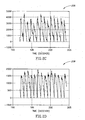
- Figs. 7 and 8 show the results of two other tests that were performed by the inventors to verify the usefulness of the CBF indicator signal, using healthy volunteers.
- CBF indicators 702 (in Fig. 7 ) and 802 and 806 (in Fig. 8 ) were defined as the ratio of the maximum slope of the IPG signal to the maximum slope of one of the PPG signals, but the maximum slopes were not normalized to the amplitudes of the respective signals.
- This method of calculating the CBF indicator generally gave better results in these two tests, than using normalized maximum slopes did.
- the smoothing method, and the definition of "good" cardiac cycles, were the same as for CBF indicator 402 in Figs. 4-6 .
- the change in CBF indicator 702 is due largely to changes in the PPG signal, which decreases when the level of carbon dioxide increases, because the brain constricts peripheral arteries of the head, in order to assure a continued adequate supply of oxygen to the brain.
- a smoothed TCD signal 704 a standard indicator for cerebral blood flow, shows a similar rise when the level of carbon dioxide rises.
- Fig. 8 illustrates the effect of cognitive activity on cerebral blood flow.
- CBF indicator 802 was calculated using the PPG signal from the left side of the head.
- CBF indicator 802 should indicate specifically the blood flow in the left side of the brain, since the brain is known to constrict or relax the peripheral arteries separately on either the left or the right side of the head, in order to regulate the blood flow on the corresponding sides of the brain.
- the subject was presented with nine multiplication problems, and asked to solve them in his head, at the times indicated by arrows 804.
- Mental arithmetic is known to be an activity primarily of the left side of the brain, and during the time the subject was solving the problems, CBF indicator 802 showed an increase in left cerebral blood flow, with about a two minute delay.
- CBF indicator 806 which was calculated using the PPG signal from the right side of the head, shows no such increase, indicating that there was no increase in right cerebral blood flow during this period. CBF indicator 806 may even show a slight decrease during this period. The changes in both CBF indicators are due primarily to changes in the PPG signal.
Landscapes
- Health & Medical Sciences (AREA)
- Life Sciences & Earth Sciences (AREA)
- Engineering & Computer Science (AREA)
- Surgery (AREA)
- General Health & Medical Sciences (AREA)
- Physics & Mathematics (AREA)
- Veterinary Medicine (AREA)
- Biophysics (AREA)
- Pathology (AREA)
- Public Health (AREA)
- Biomedical Technology (AREA)
- Heart & Thoracic Surgery (AREA)
- Medical Informatics (AREA)
- Molecular Biology (AREA)
- Animal Behavior & Ethology (AREA)
- Physiology (AREA)
- Neurology (AREA)
- Hematology (AREA)
- Radiology & Medical Imaging (AREA)
- Neurosurgery (AREA)
- Nuclear Medicine, Radiotherapy & Molecular Imaging (AREA)
- Psychology (AREA)
- Artificial Intelligence (AREA)
- Computer Vision & Pattern Recognition (AREA)
- Psychiatry (AREA)
- Signal Processing (AREA)
- Cardiology (AREA)
- Measuring Pulse, Heart Rate, Blood Pressure Or Blood Flow (AREA)
Claims (23)
- Procédé d'estimation d'un flux sanguin cérébral par l'analyse de signaux IPG, c'est-à-dire de pléthysmographie à impédance, et PPG, c'est-à-dire de photopléthysmographie, de la tête, le procédé comprenant les étapes consistant à :a) trouver une pente maximale ou une plus grande pente négative du signal IPG, à l'intérieur d'au moins une portion du cycle cardiaque ;b) trouver une pente maximale ou une plus grande pente négative du signal PPG, à l'intérieur d'au moins une portion du cycle cardiaque ;c) trouver un rapport entre la pente maximale ou la plus grande pente négative du signal IPG et la pente maximale ou la plus grande pente négative du signal PPG ; etd) calculer un indicateur de flux sanguin cérébral à partir du rapport.
- Procédé selon la revendication 1, dans lequel le fait de trouver la pente maximale ou la plus grande pente négative comprend le fait de trouver la pente maximale, à la fois pour les signaux IPG et PPG, et le fait de trouver un rapport comprend le fait de trouver un rapport des pentes maximales.
- Procédé selon la revendication 2, dans lequel les pentes maximales sont maximales à l'intérieur d'une portion avant du cycle cardiaque.
- Procédé selon la revendication 1, dans lequel le fait de trouver la pente maximale ou la plus grande pente négative comprend le fait de trouver la plus grande pente négative, à la fois pour les signaux IPG et PPG, et le fait de trouver un rapport comprend le fait de trouver un rapport des plus grandes pentes négatives.
- Procédé selon la revendication 4, dans lequel les plus grandes pentes négatives sont les plus négatives à l'intérieur d'une portion arrière du cycle cardiaque.
- Procédé selon l'une quelconque des revendications précédentes, dans lequel la pente maximale ou la plus grande pente négative d'au moins l'un des signaux est normalisée sur une mesure de l'amplitude dudit signal.
- Procédé selon la revendication 6, dans lequel la mesure de l'amplitude est l'amplitude de crête à crête dudit signal durant le cycle cardiaque.
- Procédé selon la revendication 6, dans lequel la mesure de l'amplitude est une valeur moyenne dudit signal durant le cycle cardiaque.
- Procédé selon l'une quelconque des revendications précédentes, dans lequel le signal PPG provient d'un capteur PPG sur le côté gauche de la tête.
- Procédé selon l'une quelconque des revendications 1 à 8, dans lequel le signal PPG provient d'un capteur PPG sur le côté droit de la tête.
- Procédé selon l'une quelconque des revendications 1 à 8, dans lequel le signal PPG est une moyenne de signaux provenant d'un capteur PPG sur le côté gauche de la tête et d'un capteur PPG sur le côté droit de la tête.
- Procédé d'estimation d'un flux sanguin cérébral variable dans le temps, comprenant les étapes consistant à :a) obtenir un signal IPG, c'est-à-dire de pléthysmographie à impédance, variable dans le temps, de la tête ;b) obtenir un signal PPG, c'est-à-dire de photopléthysmographie, variable dans le temps, de la tête ;c) utiliser les signaux IPG et PPG pour calculer un indicateur variable dans le temps pour le flux sanguin cérébral ; etd) effectuer un traitement de données sur un ou plusieurs du signal IPG, du signal PPG et de l'indicateur de flux sanguin cérébral, pour réduire du bruit ou des artefacts, ou les deux.
- Procédé selon la revendication 12, dans lequel le fait d'effectuer un traitement de données comprend l'élimination de données du signal IPG, du signal PPG, ou des deux, pour des cycles cardiaques qui répondent à un ou plusieurs critères d'élimination.
- Procédé selon la revendication 13, dans lequel les critères comprennent le fait d'avoir une durée en dehors d'une plage attendue.
- Procédé selon la revendication 14, dans lequel la plage attendue présente un maximum entre 1,3 et 2 fois une durée moyenne des cycles cardiaques.
- Procédé selon l'une quelconque des revendications 13 à 15, dans lequel les critères comprennent le fait qu'un ou deux du signal IPG et du signal PPG présente une corrélation croisée au-dessous d'un seuil, entre ce cycle cardiaque et le cycle cardiaque suivant.
- Procédé selon l'une quelconque des revendications 13 à 15, dans lequel les critères comprennent le fait qu'un ou deux du signal IPG et du signal PPG présente une corrélation croisée au-dessous d'un seuil, entre ce cycle cardiaque et le cycle cardiaque précédent.
- Procédé selon la revendication 16 ou 17, dans lequel le seuil se trouve entre +0,5 et +0,8.
- Procédé selon l'une quelconque des revendications 12 à 18, dans lequel le fait d'effectuer un traitement de données comprend le fait de réduire des artefacts respiratoires dans le signal IPG, le signal PPG, ou les deux.
- Procédé selon l'une quelconque des revendications 12 à 19, dans lequel le calcul de l'indicateur de flux sanguin cérébral comprend l'utilisation du procédé selon l'une quelconque des revendications 1 à 11.
- Procédé selon l'une quelconque des revendications 12 à 20, dans lequel l'exécution du traitement de données comprend le lissage de l'indicateur de flux sanguin cérébral.
- Procédé selon la revendication 21, dans lequel le lissage comprend le fait de trouver une moyenne sur un intervalle de temps.
- Procédé selon la revendication 21 ou 22, dans lequel le lissage comprend l'utilisation d'une échelle chronologique qui est ajustée de façon adaptative, en fonction du comportement de l'indicateur de flux sanguin cérébral comme une fonction du temps.
Applications Claiming Priority (3)
| Application Number | Priority Date | Filing Date | Title |
|---|---|---|---|
| PCT/IL2005/000632 WO2006011128A1 (fr) | 2004-07-15 | 2005-06-15 | Appareil de surveillance de perfusion cerebrale |
| PCT/IL2005/000631 WO2006006143A1 (fr) | 2004-07-15 | 2005-06-15 | Dispositif permettant de surveiller l'ecoulement sanguin vers le cerveau |
| PCT/IB2006/050174 WO2006134501A1 (fr) | 2005-06-15 | 2006-01-17 | Appareil de surveillance de perfusion cerebrale |
Publications (2)
| Publication Number | Publication Date |
|---|---|
| EP1895902A1 EP1895902A1 (fr) | 2008-03-12 |
| EP1895902B1 true EP1895902B1 (fr) | 2009-11-11 |
Family
ID=36384512
Family Applications (1)
| Application Number | Title | Priority Date | Filing Date |
|---|---|---|---|
| EP06701857A Not-in-force EP1895902B1 (fr) | 2005-06-15 | 2006-01-17 | Appareil de surveillance de perfusion cerebrale |
Country Status (2)
| Country | Link |
|---|---|
| EP (1) | EP1895902B1 (fr) |
| WO (1) | WO2006134501A1 (fr) |
Families Citing this family (6)
| Publication number | Priority date | Publication date | Assignee | Title |
|---|---|---|---|---|
| US7998080B2 (en) | 2002-01-15 | 2011-08-16 | Orsan Medical Technologies Ltd. | Method for monitoring blood flow to brain |
| US8211031B2 (en) | 2002-01-15 | 2012-07-03 | Orsan Medical Technologies Ltd. | Non-invasive intracranial monitor |
| JP4904263B2 (ja) | 2004-07-15 | 2012-03-28 | オーサン メディカル テクノロジーズ リミテッド | 脳灌流監視装置 |
| CN102238906B (zh) * | 2008-10-07 | 2013-11-06 | 奥森医疗科技有限公司 | 急性中风的诊断 |
| US20120203122A1 (en) | 2011-02-09 | 2012-08-09 | Opher Kinrot | Devices and methods for monitoring cerebral hemodynamic conditions |
| CN110769748B (zh) * | 2017-04-18 | 2023-08-29 | 皇家飞利浦有限公司 | 伪迹宽容的脉搏率变异性测量 |
Family Cites Families (1)
| Publication number | Priority date | Publication date | Assignee | Title |
|---|---|---|---|---|
| WO2003059164A2 (fr) * | 2002-01-15 | 2003-07-24 | Orsan Medical Equipment Ltd. | Dispositif de controle de l'ecoulement sanguin vers le cerveau |
-
2006
- 2006-01-17 EP EP06701857A patent/EP1895902B1/fr not_active Not-in-force
- 2006-01-17 WO PCT/IB2006/050174 patent/WO2006134501A1/fr active Application Filing
Also Published As
| Publication number | Publication date |
|---|---|
| WO2006134501A1 (fr) | 2006-12-21 |
| EP1895902A1 (fr) | 2008-03-12 |
Similar Documents
| Publication | Publication Date | Title |
|---|---|---|
| US8512253B2 (en) | Cerebral perfusion monitor | |
| EP2344033B1 (fr) | Diagnostic d'accidents cérébrovasculaires aigus | |
| US7727157B2 (en) | Non-invasive measurement of suprasystolic signals | |
| CA2422801C (fr) | Mesure non invasive de signaux suprasystoliques | |
| EP1786316B1 (fr) | Appareil de surveillance de perfusion cerebrale | |
| JP2016519606A (ja) | 生体インピーダンスを使用した脳の生理学的パラメータの測定 | |
| US20130274615A1 (en) | Measurement of Cerebral Physiologic Parameters Using Bioimpedance | |
| EP1895902B1 (fr) | Appareil de surveillance de perfusion cerebrale | |
| JP2018531673A (ja) | 脳の膨張と移動の少なくとも一方の亢進を検出する装置および方法 | |
| US20220409117A1 (en) | Method and apparatus for detecting changes in blood flow in the head of a subject | |
| Maqsood et al. | Exploratory analysis of spontaneous versus paced breathing on heart rate variability in veterans with combat‐related traumatic injury | |
| Krakauskaitė | Assessment of a non-invasive electronic cerebrovascular autoregulation monitoring system | |
| Bechara | Em Activity |
Legal Events
| Date | Code | Title | Description |
|---|---|---|---|
| PUAI | Public reference made under article 153(3) epc to a published international application that has entered the european phase |
Free format text: ORIGINAL CODE: 0009012 |
|
| 17P | Request for examination filed |
Effective date: 20071220 |
|
| AK | Designated contracting states |
Kind code of ref document: A1 Designated state(s): AT BE BG CH CY CZ DE DK EE ES FI FR GB GR HU IE IS IT LI LT LU LV MC NL PL PT RO SE SI SK TR |
|
| DAX | Request for extension of the european patent (deleted) | ||
| GRAP | Despatch of communication of intention to grant a patent |
Free format text: ORIGINAL CODE: EPIDOSNIGR1 |
|
| GRAS | Grant fee paid |
Free format text: ORIGINAL CODE: EPIDOSNIGR3 |
|
| GRAA | (expected) grant |
Free format text: ORIGINAL CODE: 0009210 |
|
| AK | Designated contracting states |
Kind code of ref document: B1 Designated state(s): AT BE BG CH CY CZ DE DK EE ES FI FR GB GR HU IE IS IT LI LT LU LV MC NL PL PT RO SE SI SK TR |
|
| REG | Reference to a national code |
Ref country code: GB Ref legal event code: FG4D |
|
| REG | Reference to a national code |
Ref country code: CH Ref legal event code: EP |
|
| REG | Reference to a national code |
Ref country code: IE Ref legal event code: FG4D |
|
| REF | Corresponds to: |
Ref document number: 602006010378 Country of ref document: DE Date of ref document: 20091224 Kind code of ref document: P |
|
| REG | Reference to a national code |
Ref country code: PT Ref legal event code: SC4A Free format text: AVAILABILITY OF NATIONAL TRANSLATION Effective date: 20100122 |
|
| REG | Reference to a national code |
Ref country code: SE Ref legal event code: TRGR |
|
| REG | Reference to a national code |
Ref country code: DK Ref legal event code: T3 |
|
| REG | Reference to a national code |
Ref country code: ES Ref legal event code: FG2A Ref document number: 2336137 Country of ref document: ES Kind code of ref document: T3 |
|
| LTIE | Lt: invalidation of european patent or patent extension |
Effective date: 20091111 |
|
| PG25 | Lapsed in a contracting state [announced via postgrant information from national office to epo] |
Ref country code: FI Free format text: LAPSE BECAUSE OF FAILURE TO SUBMIT A TRANSLATION OF THE DESCRIPTION OR TO PAY THE FEE WITHIN THE PRESCRIBED TIME-LIMIT Effective date: 20091111 Ref country code: IS Free format text: LAPSE BECAUSE OF FAILURE TO SUBMIT A TRANSLATION OF THE DESCRIPTION OR TO PAY THE FEE WITHIN THE PRESCRIBED TIME-LIMIT Effective date: 20100311 Ref country code: LT Free format text: LAPSE BECAUSE OF FAILURE TO SUBMIT A TRANSLATION OF THE DESCRIPTION OR TO PAY THE FEE WITHIN THE PRESCRIBED TIME-LIMIT Effective date: 20091111 |
|
| PG25 | Lapsed in a contracting state [announced via postgrant information from national office to epo] |
Ref country code: PL Free format text: LAPSE BECAUSE OF FAILURE TO SUBMIT A TRANSLATION OF THE DESCRIPTION OR TO PAY THE FEE WITHIN THE PRESCRIBED TIME-LIMIT Effective date: 20091111 Ref country code: LV Free format text: LAPSE BECAUSE OF FAILURE TO SUBMIT A TRANSLATION OF THE DESCRIPTION OR TO PAY THE FEE WITHIN THE PRESCRIBED TIME-LIMIT Effective date: 20091111 Ref country code: CY Free format text: LAPSE BECAUSE OF FAILURE TO SUBMIT A TRANSLATION OF THE DESCRIPTION OR TO PAY THE FEE WITHIN THE PRESCRIBED TIME-LIMIT Effective date: 20091111 Ref country code: SI Free format text: LAPSE BECAUSE OF FAILURE TO SUBMIT A TRANSLATION OF THE DESCRIPTION OR TO PAY THE FEE WITHIN THE PRESCRIBED TIME-LIMIT Effective date: 20091111 |
|
| PG25 | Lapsed in a contracting state [announced via postgrant information from national office to epo] |
Ref country code: RO Free format text: LAPSE BECAUSE OF FAILURE TO SUBMIT A TRANSLATION OF THE DESCRIPTION OR TO PAY THE FEE WITHIN THE PRESCRIBED TIME-LIMIT Effective date: 20091111 Ref country code: EE Free format text: LAPSE BECAUSE OF FAILURE TO SUBMIT A TRANSLATION OF THE DESCRIPTION OR TO PAY THE FEE WITHIN THE PRESCRIBED TIME-LIMIT Effective date: 20091111 Ref country code: BG Free format text: LAPSE BECAUSE OF FAILURE TO SUBMIT A TRANSLATION OF THE DESCRIPTION OR TO PAY THE FEE WITHIN THE PRESCRIBED TIME-LIMIT Effective date: 20100211 |
|
| PG25 | Lapsed in a contracting state [announced via postgrant information from national office to epo] |
Ref country code: CZ Free format text: LAPSE BECAUSE OF FAILURE TO SUBMIT A TRANSLATION OF THE DESCRIPTION OR TO PAY THE FEE WITHIN THE PRESCRIBED TIME-LIMIT Effective date: 20091111 Ref country code: SK Free format text: LAPSE BECAUSE OF FAILURE TO SUBMIT A TRANSLATION OF THE DESCRIPTION OR TO PAY THE FEE WITHIN THE PRESCRIBED TIME-LIMIT Effective date: 20091111 |
|
| PLBE | No opposition filed within time limit |
Free format text: ORIGINAL CODE: 0009261 |
|
| STAA | Information on the status of an ep patent application or granted ep patent |
Free format text: STATUS: NO OPPOSITION FILED WITHIN TIME LIMIT |
|
| 26N | No opposition filed |
Effective date: 20100812 |
|
| PG25 | Lapsed in a contracting state [announced via postgrant information from national office to epo] |
Ref country code: GR Free format text: LAPSE BECAUSE OF FAILURE TO SUBMIT A TRANSLATION OF THE DESCRIPTION OR TO PAY THE FEE WITHIN THE PRESCRIBED TIME-LIMIT Effective date: 20100212 |
|
| PGFP | Annual fee paid to national office [announced via postgrant information from national office to epo] |
Ref country code: LU Payment date: 20101214 Year of fee payment: 6 |
|
| PGFP | Annual fee paid to national office [announced via postgrant information from national office to epo] |
Ref country code: IE Payment date: 20120124 Year of fee payment: 7 Ref country code: MC Payment date: 20120111 Year of fee payment: 7 Ref country code: CH Payment date: 20120123 Year of fee payment: 7 |
|
| PGFP | Annual fee paid to national office [announced via postgrant information from national office to epo] |
Ref country code: PT Payment date: 20120117 Year of fee payment: 7 |
|
| PGFP | Annual fee paid to national office [announced via postgrant information from national office to epo] |
Ref country code: DK Payment date: 20120119 Year of fee payment: 7 Ref country code: SE Payment date: 20120120 Year of fee payment: 7 Ref country code: BE Payment date: 20120117 Year of fee payment: 7 |
|
| PGFP | Annual fee paid to national office [announced via postgrant information from national office to epo] |
Ref country code: NL Payment date: 20120125 Year of fee payment: 7 |
|
| PG25 | Lapsed in a contracting state [announced via postgrant information from national office to epo] |
Ref country code: HU Free format text: LAPSE BECAUSE OF FAILURE TO SUBMIT A TRANSLATION OF THE DESCRIPTION OR TO PAY THE FEE WITHIN THE PRESCRIBED TIME-LIMIT Effective date: 20100512 |
|
| PG25 | Lapsed in a contracting state [announced via postgrant information from national office to epo] |
Ref country code: TR Free format text: LAPSE BECAUSE OF FAILURE TO SUBMIT A TRANSLATION OF THE DESCRIPTION OR TO PAY THE FEE WITHIN THE PRESCRIBED TIME-LIMIT Effective date: 20091111 |
|
| PGFP | Annual fee paid to national office [announced via postgrant information from national office to epo] |
Ref country code: AT Payment date: 20120111 Year of fee payment: 7 |
|
| PGFP | Annual fee paid to national office [announced via postgrant information from national office to epo] |
Ref country code: ES Payment date: 20120118 Year of fee payment: 7 |
|
| REG | Reference to a national code |
Ref country code: PT Ref legal event code: MM4A Free format text: LAPSE DUE TO NON-PAYMENT OF FEES Effective date: 20130717 |
|
| BERE | Be: lapsed |
Owner name: ORSAN MEDICAL TECHNOLOGIES LTD. Effective date: 20130131 |
|
| REG | Reference to a national code |
Ref country code: NL Ref legal event code: V1 Effective date: 20130801 |
|
| REG | Reference to a national code |
Ref country code: DK Ref legal event code: EBP |
|
| PG25 | Lapsed in a contracting state [announced via postgrant information from national office to epo] |
Ref country code: MC Free format text: LAPSE BECAUSE OF NON-PAYMENT OF DUE FEES Effective date: 20130131 |
|
| REG | Reference to a national code |
Ref country code: CH Ref legal event code: PL |
|
| REG | Reference to a national code |
Ref country code: SE Ref legal event code: EUG |
|
| REG | Reference to a national code |
Ref country code: AT Ref legal event code: MM01 Ref document number: 447886 Country of ref document: AT Kind code of ref document: T Effective date: 20130131 |
|
| REG | Reference to a national code |
Ref country code: IE Ref legal event code: MM4A |
|
| PG25 | Lapsed in a contracting state [announced via postgrant information from national office to epo] |
Ref country code: NL Free format text: LAPSE BECAUSE OF NON-PAYMENT OF DUE FEES Effective date: 20130801 Ref country code: CH Free format text: LAPSE BECAUSE OF NON-PAYMENT OF DUE FEES Effective date: 20130131 Ref country code: SE Free format text: LAPSE BECAUSE OF NON-PAYMENT OF DUE FEES Effective date: 20130118 Ref country code: LI Free format text: LAPSE BECAUSE OF NON-PAYMENT OF DUE FEES Effective date: 20130131 Ref country code: PT Free format text: LAPSE BECAUSE OF NON-PAYMENT OF DUE FEES Effective date: 20130717 Ref country code: BE Free format text: LAPSE BECAUSE OF NON-PAYMENT OF DUE FEES Effective date: 20130131 Ref country code: AT Free format text: LAPSE BECAUSE OF NON-PAYMENT OF DUE FEES Effective date: 20130131 |
|
| PG25 | Lapsed in a contracting state [announced via postgrant information from national office to epo] |
Ref country code: IE Free format text: LAPSE BECAUSE OF NON-PAYMENT OF DUE FEES Effective date: 20130117 Ref country code: DK Free format text: LAPSE BECAUSE OF NON-PAYMENT OF DUE FEES Effective date: 20130131 |
|
| REG | Reference to a national code |
Ref country code: ES Ref legal event code: FD2A Effective date: 20140321 |
|
| PG25 | Lapsed in a contracting state [announced via postgrant information from national office to epo] |
Ref country code: ES Free format text: LAPSE BECAUSE OF NON-PAYMENT OF DUE FEES Effective date: 20130118 |
|
| PG25 | Lapsed in a contracting state [announced via postgrant information from national office to epo] |
Ref country code: LU Free format text: LAPSE BECAUSE OF NON-PAYMENT OF DUE FEES Effective date: 20130117 |
|
| REG | Reference to a national code |
Ref country code: FR Ref legal event code: PLFP Year of fee payment: 11 |
|
| PGFP | Annual fee paid to national office [announced via postgrant information from national office to epo] |
Ref country code: FR Payment date: 20151208 Year of fee payment: 11 |
|
| PGFP | Annual fee paid to national office [announced via postgrant information from national office to epo] |
Ref country code: DE Payment date: 20160112 Year of fee payment: 11 Ref country code: IT Payment date: 20160127 Year of fee payment: 11 |
|
| PGFP | Annual fee paid to national office [announced via postgrant information from national office to epo] |
Ref country code: GB Payment date: 20160113 Year of fee payment: 11 |
|
| REG | Reference to a national code |
Ref country code: DE Ref legal event code: R119 Ref document number: 602006010378 Country of ref document: DE |
|
| GBPC | Gb: european patent ceased through non-payment of renewal fee |
Effective date: 20170117 |
|
| REG | Reference to a national code |
Ref country code: FR Ref legal event code: ST Effective date: 20170929 |
|
| PG25 | Lapsed in a contracting state [announced via postgrant information from national office to epo] |
Ref country code: FR Free format text: LAPSE BECAUSE OF NON-PAYMENT OF DUE FEES Effective date: 20170131 |
|
| PG25 | Lapsed in a contracting state [announced via postgrant information from national office to epo] |
Ref country code: GB Free format text: LAPSE BECAUSE OF NON-PAYMENT OF DUE FEES Effective date: 20170117 Ref country code: DE Free format text: LAPSE BECAUSE OF NON-PAYMENT OF DUE FEES Effective date: 20170801 |
|
| PG25 | Lapsed in a contracting state [announced via postgrant information from national office to epo] |
Ref country code: IT Free format text: LAPSE BECAUSE OF NON-PAYMENT OF DUE FEES Effective date: 20170117 |