EP1895751A1 - DMB terminal for enabling simultaneous DMB viewing and phone call and method therefor - Google Patents
DMB terminal for enabling simultaneous DMB viewing and phone call and method therefor Download PDFInfo
- Publication number
- EP1895751A1 EP1895751A1 EP07022221A EP07022221A EP1895751A1 EP 1895751 A1 EP1895751 A1 EP 1895751A1 EP 07022221 A EP07022221 A EP 07022221A EP 07022221 A EP07022221 A EP 07022221A EP 1895751 A1 EP1895751 A1 EP 1895751A1
- Authority
- EP
- European Patent Office
- Prior art keywords
- dmb
- module
- switching
- call
- broadcasting
- Prior art date
- Legal status (The legal status is an assumption and is not a legal conclusion. Google has not performed a legal analysis and makes no representation as to the accuracy of the status listed.)
- Ceased
Links
Images


Classifications
-
- H—ELECTRICITY
- H04—ELECTRIC COMMUNICATION TECHNIQUE
- H04M—TELEPHONIC COMMUNICATION
- H04M1/00—Substation equipment, e.g. for use by subscribers
- H04M1/72—Mobile telephones; Cordless telephones, i.e. devices for establishing wireless links to base stations without route selection
- H04M1/724—User interfaces specially adapted for cordless or mobile telephones
- H04M1/72403—User interfaces specially adapted for cordless or mobile telephones with means for local support of applications that increase the functionality
- H04M1/7243—User interfaces specially adapted for cordless or mobile telephones with means for local support of applications that increase the functionality with interactive means for internal management of messages
- H04M1/72436—User interfaces specially adapted for cordless or mobile telephones with means for local support of applications that increase the functionality with interactive means for internal management of messages for text messaging, e.g. short messaging services [SMS] or e-mails
-
- H—ELECTRICITY
- H04—ELECTRIC COMMUNICATION TECHNIQUE
- H04H—BROADCAST COMMUNICATION
- H04H40/00—Arrangements specially adapted for receiving broadcast information
- H04H40/18—Arrangements characterised by circuits or components specially adapted for receiving
-
- H—ELECTRICITY
- H04—ELECTRIC COMMUNICATION TECHNIQUE
- H04N—PICTORIAL COMMUNICATION, e.g. TELEVISION
- H04N21/00—Selective content distribution, e.g. interactive television or video on demand [VOD]
- H04N21/20—Servers specifically adapted for the distribution of content, e.g. VOD servers; Operations thereof
- H04N21/25—Management operations performed by the server for facilitating the content distribution or administrating data related to end-users or client devices, e.g. end-user or client device authentication, learning user preferences for recommending movies
- H04N21/262—Content or additional data distribution scheduling, e.g. sending additional data at off-peak times, updating software modules, calculating the carousel transmission frequency, delaying a video stream transmission, generating play-lists
-
- H—ELECTRICITY
- H04—ELECTRIC COMMUNICATION TECHNIQUE
- H04M—TELEPHONIC COMMUNICATION
- H04M1/00—Substation equipment, e.g. for use by subscribers
- H04M1/72—Mobile telephones; Cordless telephones, i.e. devices for establishing wireless links to base stations without route selection
- H04M1/724—User interfaces specially adapted for cordless or mobile telephones
- H04M1/72403—User interfaces specially adapted for cordless or mobile telephones with means for local support of applications that increase the functionality
-
- H—ELECTRICITY
- H04—ELECTRIC COMMUNICATION TECHNIQUE
- H04M—TELEPHONIC COMMUNICATION
- H04M1/00—Substation equipment, e.g. for use by subscribers
- H04M1/72—Mobile telephones; Cordless telephones, i.e. devices for establishing wireless links to base stations without route selection
- H04M1/724—User interfaces specially adapted for cordless or mobile telephones
- H04M1/72484—User interfaces specially adapted for cordless or mobile telephones wherein functions are triggered by incoming communication events
-
- H—ELECTRICITY
- H04—ELECTRIC COMMUNICATION TECHNIQUE
- H04W—WIRELESS COMMUNICATION NETWORKS
- H04W4/00—Services specially adapted for wireless communication networks; Facilities therefor
- H04W4/12—Messaging; Mailboxes; Announcements
- H04W4/14—Short messaging services, e.g. short message services [SMS] or unstructured supplementary service data [USSD]
-
- G—PHYSICS
- G06—COMPUTING OR CALCULATING; COUNTING
- G06F—ELECTRIC DIGITAL DATA PROCESSING
- G06F3/00—Input arrangements for transferring data to be processed into a form capable of being handled by the computer; Output arrangements for transferring data from processing unit to output unit, e.g. interface arrangements
- G06F3/01—Input arrangements or combined input and output arrangements for interaction between user and computer
- G06F3/048—Interaction techniques based on graphical user interfaces [GUI]
- G06F3/0484—Interaction techniques based on graphical user interfaces [GUI] for the control of specific functions or operations, e.g. selecting or manipulating an object, an image or a displayed text element, setting a parameter value or selecting a range
- G06F3/04842—Selection of displayed objects or displayed text elements
-
- G—PHYSICS
- G06—COMPUTING OR CALCULATING; COUNTING
- G06F—ELECTRIC DIGITAL DATA PROCESSING
- G06F3/00—Input arrangements for transferring data to be processed into a form capable of being handled by the computer; Output arrangements for transferring data from processing unit to output unit, e.g. interface arrangements
- G06F3/01—Input arrangements or combined input and output arrangements for interaction between user and computer
- G06F3/048—Interaction techniques based on graphical user interfaces [GUI]
- G06F3/0487—Interaction techniques based on graphical user interfaces [GUI] using specific features provided by the input device, e.g. functions controlled by the rotation of a mouse with dual sensing arrangements, or of the nature of the input device, e.g. tap gestures based on pressure sensed by a digitiser
- G06F3/0489—Interaction techniques based on graphical user interfaces [GUI] using specific features provided by the input device, e.g. functions controlled by the rotation of a mouse with dual sensing arrangements, or of the nature of the input device, e.g. tap gestures based on pressure sensed by a digitiser using dedicated keyboard keys or combinations thereof
-
- G—PHYSICS
- G06—COMPUTING OR CALCULATING; COUNTING
- G06F—ELECTRIC DIGITAL DATA PROCESSING
- G06F3/00—Input arrangements for transferring data to be processed into a form capable of being handled by the computer; Output arrangements for transferring data from processing unit to output unit, e.g. interface arrangements
- G06F3/16—Sound input; Sound output
-
- H—ELECTRICITY
- H04—ELECTRIC COMMUNICATION TECHNIQUE
- H04H—BROADCAST COMMUNICATION
- H04H2201/00—Aspects of broadcast communication
- H04H2201/10—Aspects of broadcast communication characterised by the type of broadcast system
- H04H2201/20—Aspects of broadcast communication characterised by the type of broadcast system digital audio broadcasting [DAB]
Definitions
- the present invention relates generally to a terminal for receiving Digital Multimedia Broadcasting (DMB), and in particular, to a DMB terminal having the dual functions of DMB reception and mobile phone call enabled.
- DMB Digital Multimedia Broadcasting
- SMS Short Message Service
- the controller of his portable terminal transitions from the current operation state to another operation state for performing the SMS function according to a key pressed by the user.
- This kind of state transition is triggered as the controller senses generation of an event such as input of a predetermined key from the user.
- a device that performs such an event-triggered state transition is called a "state machine.”
- FIG. 1 is an event-triggered state transition diagram for a typical DMB terminal.
- the DMB terminal operates in a User interface (Ul) state 100.
- the Ul state 100 is divided into an idle state 102, a menu state 104 for displaying a predetermined menu, a call state 106 for call termination and call origination, and a DMB state 108 for allowing the user to view DMB.
- the Ul state 100 stays in the idle state 102.
- the DMB terminal transitions from the idle state 102 to the menu state 104 to display a menu.
- the DMB terminal transitions to the call state 106 in response to the event, for call processing. If the user presses a key designated for DMB viewing, the DMB terminal transitions to the DMB state 108 to receive and output DMB data.
- the typical DMB terminal working in the operation states illustrated in FIG. 1 is configured to be in only one operation state at a given time. For instance, upon incoming of a call during providing the DMB service to the user in the DMB state 108, the DMB terminal transitions to the call state 106 for call termination, if the user accepts the incoming call. Thus, the DMB operation in the DMB state 108 is terminated.
- the typical DMB terminal needs to perform another operation during the DMB service, it transitions to an operation state corresponding to the new operation, terminating DMB reception.
- the present invention is to substantially solve at least the above problems and/or disadvantages and to provide at least the advantages below. It is the object of the present invention to provide an apparatus and method for enabling a user to continuously view DMB without interruptions, while a DMB terminal carries out another operation during the DMB viewing.
- An aspect of the present invention is to provide an apparatus and method for enabling a user to view DMB while conducting a call.
- the above is achieved by providing a DMB terminal for enabling simultaneous DMB viewing and call, and a method therefor.
- a DMB-modem switch unit switches an image output path for outputting image information, an audible sound output path for outputting audible sounds, and a key input path for receiving a key input signal from a user to the DMB module or the modem module.
- a DMB-modem switch controller upon user selection of an operation mode, controls the DMB-modem switch unit to switch the image output path, the audible sound output path, and the key input path to a module corresponding to the selected operation mode.
- a communication method for enabling simultaneous DMB viewing and call in a DMB having a DMB module for providing a DMB service and a modem module for providing mobile communication functionality upon user selection of a DMB reception mode, the image output path, the audible sound output path, and the key input path are switched to the DMB module by the modem module.
- DMB data is output through the audible sound output path and the image output path and a key input is received from a user through the key input path in the DMB module.
- the image output path, the audible sound output path, and the key input path are switched to the modem module by the modem module.
- the incoming call is processed by the modem module to allow the user to conduct a conversation. After processing the incoming call, the image output path, the audible sound output path, and the key input path are switched to the DMB module by the modem module.
- a controller is provided with a DMB module for receiving, processing, and outputting DMB data and at least one other module for performing a function other than the DMB reception function.
- Each application for driving a corresponding module is assigned a different memory working area so that applications can be run concurrently. Therefore, two or more modules can operate simultaneously at a given time.
- a switch is further provided to switch an image output path running to a display for outputting image information, an audible sound output path running to an amplifier for outputting audible sounds, and a key input path running from a keypad for providing key input received from a user through the keypad to the controller to the DMB module or the at least one other module.
- a module serving as a main control module in the controller controls the switching operation. Therefore, if the user wants another function during viewing DMB, he can use the function without terminating the DMB.
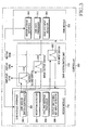
- FIG. 2 is a block diagram of a DMB terminal according to the present invention.
- the DMB terminal is assumed to have a DMB module for receiving, processing, and outputting DMB data and a modem module for performing traditional call functionality and data communications.
- a memory 202 in the DMB terminal, a memory 202, a keypad 204, a display 206, a baseband processor 210, and a Coder-DECoder (CODEC) 212 are connected to a controller 200.
- the controller 200 includes a modem module 218 for processing phone calls and data communications, and processing audio signals and data according to a wireless Internet connection protocol, and a DMB module 220 for receiving DMB data including video, audio, and information data, decoding the audio data and video data through a DMB audio decoder and a DMB video decoder, respectively, and controlling output of the decoded data.
- the controller 200 is further provided with a DMB-modem switch unit 216 for switching a key input path for receiving a key input signal from the user through the keypad 204, an image output path for outputting image information to the display 206, and an audible sound output path for outputting an audible sound signal to an amplifier 214 to the modem module 218 or the DMB module 220.
- a DMB-modem switch unit 216 can be implemented in hardware, needless to say, it can be implemented also in software such as a switching application.
- the controller 200 is illustrated in more detail in FIG. 3.
- the memory 202 includes a Read Only Memory (ROM), a flash memory, and a Random Access Memory (RAM).
- the ROM stores programs for processing and controlling in the controller 200, and reference data.
- the RAM provides a working memory for the controller 200 and the flash memory provides an area for storing updatable data.
- the memory 202 has an application for driving a module serving as a main control module and another application for driving another module, and provides a working area to each of the applications, when needed.
- the DMB terminal can operate two or more modules at a given time.
- the keypad 204 is provided with keys including alphanumerical keys and provides a key input received from the user to the controller 200. According to the present invention, the keypad 204 further has an output switching key. The output switching key is used to invoke an output switching function for switching only the image output path and the key input path to the DMB module 220 during an incoming call process or an outgoing call process in the modem module 218 and thus for allowing the user to view the DMB while conducting a call.
- a Radio Frequency (RF) processor 208 transmits/receives an RF signal to/from a base station. It downconverts the received RF signal to an Intermediate Frequency (IF) signal and provides the IF signal to a baseband processor 210 connected to the controller 200. It also upconverts an IF signal received from the baseband processor 210 to an RF signal and transmits the RF signal through an antenna.
- the RF processor 208 is configured to receive DMB data.
- the baseband processor 210 is a Baseband Analog (BBA) ASIC that interfaces between the controller 200 and the RF processor 208.
- the baseband processor 210 converts a digital baseband signal received from the controller 200 to an analog IF signal and provides the analog IF signal to the RF processor 208. It also converts an analog IF signal received from the RF processor 208 to a digital baseband signal and provides the digital baseband signal to the controller 200.
- BBA Baseband Analog
- the CODEC 212 is connected to a microphone and a speaker (not shown) via the amplifier 214.
- the CODEC 212 Pulse Code Modulation (PCM)-encodes a voice signal received through the microphone and outputs the resulting voice data to the controller 200. It also PCM-decodes voice data received from the controller 200 and outputs the decoded signal through the speaker.
- the amplifier 214 amplifiers the voice signal received through the microphone or the voice signal to be output through the speaker and adjusts the volume of the speaker and the gain of the microphone under the control of the controller 200. Upon receipt of an audible sound signal in DMB data from the controller 200, the amplifier 214 amplifies the audible sound signal and outputs the amplified signal through the speaker.
- FIG. 3 is a detailed block diagram of the controller 200 in the DMB terminal according to the embodiment of the present invention.
- the DMB-modem switch unit 216 includes an audible sound switch 316 for switching to the audible sound output path, an image output switch 318 for switching to the image output path, and a key input switch 320 for switching to the key input path.
- the modem module 218 includes a reception detector 304 for detecting an incoming call or an SMS (Short Message Service)/Multimedia Messaging Service (MMS) message, and a call and message processor 306 for enabling the user to conduct a call upon call termination or call origination, to read the SMS/MMS message upon receipt of the message, or to write and send the SMS/MMS message.
- a reception detector 304 for detecting an incoming call or an SMS (Short Message Service)/Multimedia Messaging Service (MMS) message
- MMS Multimedia Messaging Service
- call and message processor 306 for enabling the user to conduct a call upon call termination or call origination, to read the SMS/MMS message upon receipt of the message, or to write and send the SMS/MMS message.
- the modem module 218 is a main control module, it is provided with a DMB-modem switch controller 300 for controlling the DMB-modem switch unit 216.
- the DMB-modem switch controller 216 is a software application implemented to control
- the modem module 218 is also provided with a DMB module interface 302 for exchanging signals with the DMB module 220.
- the DMB-modem switch controller 300 may be incorporated into the DMB module interface 302.
- the modem module 218 is further provided with an output switching key input detector 308.
- the output switching key is used to invoke an output switching function for switching only the image output path and the key input path to the DMB module 220 during an incoming call process or an outgoing call process in the modem module 218 and thus for allowing the user to view the DMB while conducting a call.
- the output switching key input detector 308 detects input of the output switching key during call processing in the modem module 218. In the state where the key input path is connected to the modem module 218, the output switching key input detector 308 detects input of the output switching key. Thus, the output switching key input detector 308 can be included only in the modem module 218 as illustrated in FIG. 3.
- the DMB module 220 has a DMB data processor 312 for receiving, decoding and outputting DMB data and a send key input detector 314 for detecting input of a Send key for originating a call or sending an SMS/MMS message while the DMB module 220 is receiving and outputting DMB data.
- the DMB module 220 further includes a modem module interface 310, for exchanging signals with the modem module 218.
- the DMB-modem switch controller 300 of the modem module 218 controls the audible sound switch 316, the image output switch 318, and the key input switch 320 to switch the audible sound output path, the image output path, and the key input path to the DMB module 220.
- the DMB module 220 can output audible sounds to the amplifier 214 and image information to the display 206.
- a key input signal from the user can be provided to the DMB module 220 through the keypad 204.
- the DMB module 220 detects this event through the send key input detector 314 and transmits a send key input indication signal indicating this event to the modem module 218 through the modem module interface 310.
- the DMB-modem switch controller 300 controls the audible sound switch 316, the image output switch 318, and the key input switch 320 to switch the audible sound output path, the image output path, and the key input path to the modem module 218.
- the DMB data processor 312 of the DMB module 220 continues to receive and process DMB data irrespective of the control operation of the DMB-modem switch controller 300.
- the audible sound output path, the image output path, and the key input path have switched off from the DMB module 220, neither image information and audible sounds of the DMB data are output nor a key input from the user is provided to the DMB module 220.
- the modem module 218 Upon key input from the user, the modem module 218 sends the written message or processes the outgoing call.
- the DMB-modem switch controller 300 controls the audible sound output path, the image output path, and the key input path to be switched again to the DMB module 220. Therefore, when the user originates a call or writes and sends a message, the DMB terminal can perform call origination or send the message without terminating the DMB reception in accordance with the embodiment of the present invention.
- the DMB-modem switch controller 300 controls the audible sound output path, the image output path, and the key input path to be switched to the modem module 218 until processing of the incoming call or reception of the message is completed.
- the path switching operation of the DMB-modem switch controller 300 in the case of an incoming call or an incoming message will be described in greater detail with reference to FIGs. 5 and 6.
- FIG. 4 is a flowchart illustrating the operations of the modem module 218 and the DMB module 220 in the controller 200 when the user selects a DMB reception mode in the DMB terminal according to the present invention. These operations are performed under the assumption that the modem module 218 is a main control module.
- the modem module 218 connects the audible sound output path, the image output path, and the key input path to the DMB module 220 in step 400.
- the modem module 218 applies a DMB module enable signal to the DMB module 220.
- the DMB module 220 receives DMB data, decodes the DMB data and outputs audible sounds and image information through the audible sound output path and the image output path, respectively in step 404.
- the DMB module 220 determines whether the Send key has been pressed in step 406.
- the DMB module 220 Upon input of the Send key, the DMB module 220 provides a send key input indication signal to the modem module 218 in step 408.
- the modem module 218 monitors incoming calls or SMS/MMS messages in step 416. Upon receipt of an incoming call or an SMS/MMS message, the modem module 218 connects to the audible sound output path, the image output path, and the key input path, and processes the incoming call or message such that the user can conduct a conversation or read the message in step 418. On the contrary, if neither a call nor a message is incoming, the modem module 218 determines whether the send key input indication signal has been received from the DMB module 220 in step 410.
- the modem module 218 Upon receipt of the send key input indication signal, the modem module 218 connects to the audible sound output path, the image output path, and the key input path, and performs an outgoing call process or an SMS/MMS message writing and sending operation in step 412. Step 412 will be described in more detail with reference to FIG. 5.
- the modem module 218 After the call termination or message reception in step 418 or the call origination or message transmission in step 412, the modem module 218 connects the audible sound output path, the image output path, and the key input path again to the DMB module 220 in step 414. Notably, the operations of step 418 and step 412 have no effects on DMB reception. In these steps, the modem module 218 simply switches to the audible sound output path, the image output path, and the key input path in steps 412 and 418. Therefore, during the operations in the modem module 218, the DMB module 220 continues to receive and process the DMB data in step 404.
- an audio signal and a video signal from the DMB data are output through the display 206 and the speaker and a key input from the keypad 204 is provided to the DMB module 220.
- the user can answer the incoming call and conduct a conversation, or read the SMS/MMS message without terminating the DMB viewing. Also, the user can write and send a message or originate a call without terminating the DMB viewing.
- FIG. 5 is a detailed flowchart illustrating the call origination or message transmission in step 412 illustrated in FIG. 4.
- the modem module 218 controls the audible sound switch 316, the image output switch 318, and the key input switch 320 to switch the audible sound output path, the image output path, and the key input path to the modem module 218 in step 500.
- the modem module 218 processes an outgoing call, or enables the user to write and send an SMS/MMS message.
- the modem module 218 determines whether the output switching key has been pressed in step 504. Upon input of the output switching key in step 506, the modem module 218 switches the image output path and the key input path to the DMB module 220 so that the output of the DMB module 220 is connected to the display 206 and a key input is provided to the DMB module 220.
- the output switching key is used to invoke an output switching function for switching only the image output path and the key input path to the DMB module 220 during an incoming call process or an outgoing call process in the modem module 218 and thus for allowing the user to view the DMB while conducting a call. Detection of the input of the output switching key and the accompanying output switching operation will be described in more detail with reference to FIG. 7.
- the modem module 218 determines whether the outgoing call or message process has been completed in step 508. If the outgoing call or message process continues, the modem module 218 returns to step 504. On the contrary, upon completion of the outgoing call or message process, the modem module 218 controls the audible sound switch 316, the image switch 318, and the key input switch 320 to switch the audible sound output path, the image output path, and the key input path to the DMB module 220. Therefore, during viewing the DMB, the DMB terminal enables the user to write and send a message or to originate a call without interrupting DMB reception in accordance with the present invention. Thus, the user can enjoy the DMB without re-starting the DMB, shortly after the message transmission or the call origination.
- FIG. 6 is a detailed flowchart illustrating the call termination or message reception in step 418 illustrated in FIG. 4.
- the modem module 218 upon incoming of a call or an SMS/MMS message during viewing the DMB in step 418, alerts the user to the incoming of the call or the SMS/MMS message in step 600 [PLEASE CHANGE "416" TO "418" IN FIG. 6.]. If the user does not want to accept the incoming call or to read the SMS/MMS message, the modem module 218 returns to step 416.
- the modem module 218 controls the audible sound switch 316, the image switch 318, and the key input path 320 to switch the audible sound output path, the image output path, and the key input path to the modem module 218 in step 602.
- step 604 the modem module 218 processes the incoming call to allow the user to conduct a conversation or processes the received message to allow the user to read the message.
- the modem module 218 determines whether the output switching key has been pressed in step 606. Upon input of the output switching key, the modem module 218 switches the image output path and the key input path to the DMB module 220 in step 506.
- the DMB module 220 is able to output DMB contents to the display 206 and receive a key input from the user.
- the output switching key is used to invoke an output switching function for switching only the image output path and the key input path to the DMB module 220 during an incoming call process or an outgoing call process in the modem module 218 and thus for allowing the user to view the DMB while conducting a call.
- the detection of input of the output switching key accompanied by the output switching will be described in great detail with reference to FIG. 7.
- the modem module 218 determines whether the call process or the message processing has been completed in step 608. If the call or message process still goes on, the modem module 218 returns to step 606. Upon completion of the call or message process in step 608, the modem module 218 controls the audible sound switch 316, the image output switch 318, and the key input switch 320 to switch the audible sound output path, the image output path, and the key input path to the DMB module 220. In this way, the DMB terminal enables the user to read a received message or to answer an incoming call and conduct a conversation at any time during viewing the DMB, without terminating the DMB. Therefore, after reading the received message or ending the call, the user can return to the DMB without re-starting the DMB.
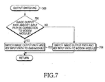
- FIG. 7 is a detailed flowchart illustrating the operation for switching the image output path and the key input path upon input of the output switching key during an incoming call process or an outgoing call process in step 506 illustrated in FIGs. 5 and 6.
- the modem module 218 detects the input of the output switching key in step 504 of FIG. 5 or in step 606 of FIG. 6.
- the output switching key is configured in hardware on the keypad 204 or in software.
- the modem module 218 determines whether it has been connected to the image output path and the key input path in step 700. If it has, the modem module 218 controls the image output switch 318 and the key input switch 320 to switch the image output path and the key input path except the audible sound output path to the DMB module 220 in step 702. Thus, even during a conversation, the user can view the DMB on the display 206 and change a broadcast channel by a key input. However, since the audible sound output path is still connected to the modem module 218, the audio signal from the DMB is not output.
- the modem module 218 controls the image output switch 318 and the key input switch 320 to switch from the DMB module 220 to the modem module 218 in step 704.
- the audible sound output path, the image output path, and the key input path are all connected to the modem module 218. If the output switching key is pressed a first time, the display 206 is switched to the DMB module 220 to allow the user to view the DMB during a call. If the output switching key is pressed a second time, the display 206 is switched to the modem module 218, for the call. In this way, the user can toggle the display output and key input between the DMB mode and the call mode.
- the DMB terminal is provided with a switch unit for switching an image output path, an audible sound output path, and a key input path between a DMB module and a modem module.
- the modem module controls the image output path, the audible sound output path, and the key input to be connected to the DMB module when the user selects a DMB reception mode. If the user wants to use the modem module during viewing the DMB, the image output path, the audible sound output path, and the key input path are simply switched to the modem module, so that the user can use the modem module without terminating the DMB reception. Thus, the user can continue to view the DMB without interruptions even though he invokes a function of the modem module during viewing the DMB.
- the present invention has been shown and described with reference to a certain preferred embodiment thereof, it is a mere exemplary application. While the function of the modem module has been described in the context of call origination/termination and transmission/reception of an SMS/MMS message, the present invention is not limited to the specific modem module function. The present invention is also applicable to other functions of the modem module during DMB viewing, such as a directory search. In addition, while the present invention has been described in the context of a DMB terminal with a DMB module and a modem module, needless to say, the present invention can be used for a DMB receiver having a Digital Video Broadcasting (DVB) module for receiving, processing and outputting DVB data.
- DVD Digital Video Broadcasting
- the present invention is also applicable to a DMB terminal having a DMB module and a Personal Digital Assistant (PDA) module. Therefore, it will be understood by those skilled in the art that various changes in form and details may be made therein without departing from the scope of the invention as defined by the appended claims.
- PDA Personal Digital Assistant
- Embodiment 1 A digital multimedia broadcasting, DMB, terminal for enabling simultaneous DMB viewing and a call function, the DMB terminal having a DMB module for providing a DMB service and a modem module for providing mobile communication functionality, and the DMB module and the modem module being able to operate separately, comprising:
- Embodiment 2 The DMB terminal of embodiment 1, wherein the modem module includes the DMB-modem switch controller.
- Embodiment 3 The DMB terminal of embodiment 1 or 2, wherein if the selected operation mode is a DMB reception mode, the DMB-modem switch controller controls the DMB-modem switch unit to switch the image output path, the audible sound output path, and the key input path to the DMB module.
- Embodiment 4 The DMB terminal of embodiment 1 or 2, wherein if the selected operation mode is a mobile communication mode, the DMB-modem switch controller controls the DMB-modem switch unit to switch the image output path, the audible sound output path, and the key input path to the modem module.
- Embodiment 5 The DMB terminal of embodiment 4, wherein the mobile communication mode is one of a call mode for processing an incoming call or an outgoing call, an SMS mode for one of reading an SMS message, or writing and sending an SMS message, and an MMS mode for one of reading an MMS message, or writing and sending an MMS message.
- the mobile communication mode is one of a call mode for processing an incoming call or an outgoing call, an SMS mode for one of reading an SMS message, or writing and sending an SMS message, and an MMS mode for one of reading an MMS message, or writing and sending an MMS message.
- Embodiment 6 The DMB terminal of embodiment 2, wherein the DMB module includes:
- Embodiment 7 The DMB terminal of embodiment 6, wherein upon receipt of the send key input indication signal, the DMB-modem switch controller controls the DMB-modem switch unit to switch the image output path, the audible sound output path, and the key input path to the modem module.
- Embodiment 8 The DMB module of one of embodiments 1 to 7, wherein when the modem module detects incoming of one of a call, an SMS message or an MMS message, the DMB-modem switch controller controls the DMB-modem switch to switch the image output path, the audible sound output path, and the key input path to the modem module according to user selection.
- Embodiment 9 The DMB terminal of one of embodiments 1 to 8, wherein the DMB-modem switch unit includes:
- Embodiment 10 The DMB terminal of embodiment 9, wherein the keypad includes an output switching key for switching the image output path and the key input path to a module other than a current connected module during an incoming call process or an outgoing call process in the modem module.
- Embodiment 11 The DMB terminal of embodiment 10, wherein upon input of the output switching key, the DMB-modem switch controller controls the image output switch and the key input switch to switch the image output path and the key input path to the DMB module.
- Embodiment 12 A communication method for enabling simultaneous DMB viewing and a call function in a digital multimedia broadcasting, DMB, terminal where a DMB module provides a DMB service and a modem module provides mobile communication functionality in a DMB terminal, the DMB module and the modem module are able to operate separately, and the modem module switches an image output path, an audible sound output path, and a key input path to one of the DMB module or the modem module, comprising the steps of:
- Embodiment 13 The communication method of embodiment 12, wherein step (3) comprises:
- Embodiment 14 The communication method of embodiment 12 or 13, wherein the DMB terminal includes an output switching key in a keypad, for allowing the modem module to switch the image output path and the key input path to a module other than a current connected module, upon processing the incoming call.
- Embodiment 15 The communication method of embodiment 14, wherein step (4) comprises:
- Embodiment 16 A communication method for enabling simultaneous DMB viewing and a call function in a digital multimedia broadcasting, DMB, where a DMB module provides a DMB service and a modem module provides mobile communication functionality, the DMB module and the modem module are able to operate separately, and the modem module switches an image output path, an audible sound output path, and a key input path to one of the DMB module or the modem module, comprising the steps of:
- Embodiment 17 The communication method of embodiment 16, wherein the message is one of an SMS message and an MMS message.
- Embodiment 18 The communication method of embodiment 16 or 17, wherein step (c) comprises:
- Embodiment 19 A communication method for enabling simultaneous DMB viewing and a call function in a digital multimedia broadcasting, DMB, where a DMB module provides a DMB service and a modem module provides mobile communication functionality in a DMB terminal, the DMB module and the modem module are able to operate separately, and the modem module switches an image output path, an audible sound output path, and a key input path to one of the DMB module or the modem module, comprising the steps of:
- Embodiment 20 The communication method of embodiment 19, wherein the send key operation is one of call origination, and writing and sending an SMS message or an MMS message according to the key input from the user.
- Embodiment 21 The communication method of embodiment 20, wherein the DMB terminal includes an output switching key in a keypad, for allowing the modem module to switch the image output path and the key input path to a module other than a current connected module during processing an outgoing call.
- Embodiment 22 The communication method of embodiment 21, wherein step (iv) comprises:
Landscapes
- Engineering & Computer Science (AREA)
- Signal Processing (AREA)
- Computer Networks & Wireless Communication (AREA)
- Human Computer Interaction (AREA)
- Business, Economics & Management (AREA)
- Multimedia (AREA)
- Databases & Information Systems (AREA)
- General Business, Economics & Management (AREA)
- Mobile Radio Communication Systems (AREA)
- Telephonic Communication Services (AREA)
- Circuits Of Receivers In General (AREA)
- Two-Way Televisions, Distribution Of Moving Picture Or The Like (AREA)
- Transceivers (AREA)
- Telephone Function (AREA)
Applications Claiming Priority (2)
| Application Number | Priority Date | Filing Date | Title |
|---|---|---|---|
| KR1020050041353A KR100557185B1 (ko) | 2005-05-17 | 2005-05-17 | 디지털 멀티미디어 방송 시청 기능과 동시에 통화 기능을수행하는 디지털 멀티미디어 방송 수신 단말기 및 동시통화 방법 |
| EP06008800A EP1725004A1 (en) | 2005-05-17 | 2006-04-27 | DMB terminal for enabling simultaneous DMB viewing and phone call and method therefor |
Related Parent Applications (1)
| Application Number | Title | Priority Date | Filing Date |
|---|---|---|---|
| EP06008800A Division EP1725004A1 (en) | 2005-05-17 | 2006-04-27 | DMB terminal for enabling simultaneous DMB viewing and phone call and method therefor |
Publications (1)
| Publication Number | Publication Date |
|---|---|
| EP1895751A1 true EP1895751A1 (en) | 2008-03-05 |
Family
ID=36603076
Family Applications (2)
| Application Number | Title | Priority Date | Filing Date |
|---|---|---|---|
| EP07022221A Ceased EP1895751A1 (en) | 2005-05-17 | 2006-04-27 | DMB terminal for enabling simultaneous DMB viewing and phone call and method therefor |
| EP06008800A Ceased EP1725004A1 (en) | 2005-05-17 | 2006-04-27 | DMB terminal for enabling simultaneous DMB viewing and phone call and method therefor |
Family Applications After (1)
| Application Number | Title | Priority Date | Filing Date |
|---|---|---|---|
| EP06008800A Ceased EP1725004A1 (en) | 2005-05-17 | 2006-04-27 | DMB terminal for enabling simultaneous DMB viewing and phone call and method therefor |
Country Status (5)
| Country | Link |
|---|---|
| US (2) | US9490925B2 (enExample) |
| EP (2) | EP1895751A1 (enExample) |
| JP (1) | JP2006325205A (enExample) |
| KR (1) | KR100557185B1 (enExample) |
| CN (2) | CN101179761A (enExample) |
Families Citing this family (7)
| Publication number | Priority date | Publication date | Assignee | Title |
|---|---|---|---|---|
| KR100663447B1 (ko) * | 2005-10-24 | 2007-01-02 | 삼성전자주식회사 | 휴대 단말기의 디지털 방송 채널 정보 표시 방법 |
| KR101199859B1 (ko) | 2006-03-21 | 2012-11-09 | 삼성전자주식회사 | 디지털 방송 수신용 단말기 및 그의 방송 프로그램 정보출력방법 |
| KR100757231B1 (ko) * | 2006-06-08 | 2007-09-10 | 삼성전자주식회사 | Dmb 휴대단말기에 있어 복수의 채널 동시 다중화면시청 방법 및 장치 |
| KR100862307B1 (ko) * | 2006-12-29 | 2008-10-13 | 엘지이노텍 주식회사 | 디엠비 및 브이에스비 튜너 모듈 |
| JP5410720B2 (ja) * | 2008-09-25 | 2014-02-05 | 日立コンシューマエレクトロニクス株式会社 | ディジタル情報信号送受信装置、およびディジタル情報信号送受信方法 |
| CA2714710C (en) * | 2010-09-03 | 2016-05-10 | Research In Motion Limited | System and method for incorporating short message service (sms) and multimedia messaging service (mms) contacts into an instant messaging interface |
| CN106921995B (zh) * | 2017-05-09 | 2019-10-25 | Oppo广东移动通信有限公司 | 马达状态控制方法、存储介质及终端 |
Citations (8)
| Publication number | Priority date | Publication date | Assignee | Title |
|---|---|---|---|---|
| US5890071A (en) * | 1994-10-27 | 1999-03-30 | Toshiba Corporation | Radio telephone set with broadcast receiving functions |
| GB2347589A (en) * | 1998-12-26 | 2000-09-06 | Samsung Electronics Co Ltd | Handling incoming calls on a portable TV phone |
| US20030097659A1 (en) * | 2001-11-16 | 2003-05-22 | Goldman Phillip Y. | Interrupting the output of media content in response to an event |
| EP1424838A2 (en) * | 2002-11-29 | 2004-06-02 | Kabushiki Kaisha Toshiba | Broadcast receiving apparatus, control method thereof, portable information terminal, and control method thereof |
| US20040204020A1 (en) * | 2002-04-05 | 2004-10-14 | Mami Kuramitsu | Communications terminal device allowing content reception and voice communication |
| EP1489818A1 (en) * | 2002-03-27 | 2004-12-22 | Mitsubishi Denki Kabushiki Kaisha | Communication apparatus and communication method |
| EP1501221A2 (en) * | 2003-07-21 | 2005-01-26 | Samsung Electronics Co., Ltd. | Apparatus and method for processing a multimedia audio signal during a voice call in a mobile digital multimedia receiver |
| US20050070327A1 (en) * | 2003-09-30 | 2005-03-31 | Casio Computer Co., Ltd. | Cellular phone having a function of receiving a television broadcasting wave |
Family Cites Families (10)
| Publication number | Priority date | Publication date | Assignee | Title |
|---|---|---|---|---|
| JP4368125B2 (ja) | 2002-04-05 | 2009-11-18 | パナソニック株式会社 | コンテンツ受信および音声通話が可能な通信端末装置 |
| JP2004062369A (ja) | 2002-07-26 | 2004-02-26 | Mitsubishi Electric Corp | マルチタスク携帯端末及び携帯通信端末 |
| KR100754647B1 (ko) | 2002-09-17 | 2007-09-05 | 삼성전자주식회사 | 휴대단말기의 텔레비전 영상신호 표시장치 및 방법 |
| KR100678204B1 (ko) * | 2002-09-17 | 2007-02-01 | 삼성전자주식회사 | 휴대단말기의 모드에 따른 영상 및 데이터 표시장치 및 방법 |
| JP2004187269A (ja) | 2002-11-20 | 2004-07-02 | Sanyo Electric Co Ltd | 携帯機器 |
| TWI241821B (en) * | 2003-04-15 | 2005-10-11 | Mobitek Comm Corp | Mobile phone architecture for acquiring or viewing image and simultaneously functioning for calling services and design method thereof |
| US7146185B2 (en) | 2003-06-12 | 2006-12-05 | Richard Lane | Mobile station-centric method for managing bandwidth and QoS in error-prone system |
| KR101014719B1 (ko) | 2004-01-09 | 2011-02-16 | 엘지전자 주식회사 | 디지털 방송 수신기의 타임 시프트 방법 |
| JP4277207B2 (ja) * | 2004-04-06 | 2009-06-10 | 日本電気株式会社 | 携帯型tv電話の送受信方法および携帯型tv電話端末 |
| KR100539884B1 (ko) * | 2004-06-19 | 2005-12-28 | 삼성전자주식회사 | 디지털 방송 데이터 출력 중 수신된 문자메시지를처리하는 이동통신단말 및 그 방법 |
-
2005
- 2005-05-17 KR KR1020050041353A patent/KR100557185B1/ko not_active Expired - Fee Related
-
2006
- 2006-04-27 EP EP07022221A patent/EP1895751A1/en not_active Ceased
- 2006-04-27 EP EP06008800A patent/EP1725004A1/en not_active Ceased
- 2006-05-02 US US11/415,751 patent/US9490925B2/en not_active Expired - Fee Related
- 2006-05-08 CN CNA2007101674285A patent/CN101179761A/zh active Pending
- 2006-05-08 CN CN2006100785271A patent/CN1866844B/zh not_active Expired - Fee Related
- 2006-05-09 JP JP2006130426A patent/JP2006325205A/ja active Pending
-
2016
- 2016-11-08 US US15/346,369 patent/US20170054841A1/en not_active Abandoned
Patent Citations (8)
| Publication number | Priority date | Publication date | Assignee | Title |
|---|---|---|---|---|
| US5890071A (en) * | 1994-10-27 | 1999-03-30 | Toshiba Corporation | Radio telephone set with broadcast receiving functions |
| GB2347589A (en) * | 1998-12-26 | 2000-09-06 | Samsung Electronics Co Ltd | Handling incoming calls on a portable TV phone |
| US20030097659A1 (en) * | 2001-11-16 | 2003-05-22 | Goldman Phillip Y. | Interrupting the output of media content in response to an event |
| EP1489818A1 (en) * | 2002-03-27 | 2004-12-22 | Mitsubishi Denki Kabushiki Kaisha | Communication apparatus and communication method |
| US20040204020A1 (en) * | 2002-04-05 | 2004-10-14 | Mami Kuramitsu | Communications terminal device allowing content reception and voice communication |
| EP1424838A2 (en) * | 2002-11-29 | 2004-06-02 | Kabushiki Kaisha Toshiba | Broadcast receiving apparatus, control method thereof, portable information terminal, and control method thereof |
| EP1501221A2 (en) * | 2003-07-21 | 2005-01-26 | Samsung Electronics Co., Ltd. | Apparatus and method for processing a multimedia audio signal during a voice call in a mobile digital multimedia receiver |
| US20050070327A1 (en) * | 2003-09-30 | 2005-03-31 | Casio Computer Co., Ltd. | Cellular phone having a function of receiving a television broadcasting wave |
Also Published As
| Publication number | Publication date |
|---|---|
| US20060233373A1 (en) | 2006-10-19 |
| EP1725004A1 (en) | 2006-11-22 |
| JP2006325205A (ja) | 2006-11-30 |
| US9490925B2 (en) | 2016-11-08 |
| US20170054841A1 (en) | 2017-02-23 |
| CN1866844A (zh) | 2006-11-22 |
| KR100557185B1 (ko) | 2006-03-03 |
| CN1866844B (zh) | 2011-08-31 |
| CN101179761A (zh) | 2008-05-14 |
Similar Documents
| Publication | Publication Date | Title |
|---|---|---|
| US20170054841A1 (en) | Dmb terminal for enabling simultaneous dmb viewing and phone call and method therefor | |
| CN101132587B (zh) | 双模式移动终端及其呼叫处理方法 | |
| US20080002668A1 (en) | Portable communication device and method for simultaneously | |
| TW200421834A (en) | Annunciators for voice and data applications in wireless communication devices | |
| US20060052081A1 (en) | Apparatus and method for displaying digital multimedia broadcasting channel information in a terminal | |
| CN1878214B (zh) | 提供呼叫服务和广播服务的方法及数字多媒体广播终端 | |
| KR100462751B1 (ko) | 이동 통신 단말기에서 문자 메시지 송신방법 | |
| KR100724860B1 (ko) | 디스플레이 모드에 따라 동작 모드를 전환하는 디지털멀티미디어 방송 수신 단말기 및 동작 모드 전환 방법 | |
| JP2006325205A5 (enExample) | ||
| US20090240842A1 (en) | Portable electronic apparatus | |
| US20070197269A1 (en) | Folder type mobile terminal and operation control method for the same | |
| KR100606018B1 (ko) | Ptt통화내용 저장 및 재생방법 | |
| KR100703455B1 (ko) | 키 입력부 위치에 따른 디스플레이 모드들을 구비하는이동통신 단말기 및 상기 디스플레이 모드들에 따른 화상정보 디스플레이 방법 | |
| KR101199860B1 (ko) | 가로모드에서 한뼘 통화가 가능한 이동통신 단말기 및 그방법 | |
| KR100330851B1 (ko) | 티브이시청중에 통화하는 티브이폰 및 그 방법 | |
| US20060294541A1 (en) | Method of performing a call in a wireless terminal | |
| KR100732991B1 (ko) | 긴급방송 자동시청기능이 구비된 디엠비단말기 및 그제어방법 | |
| KR101394278B1 (ko) | 휴대 단말기의 통화 기능 수행 방법 | |
| JP2002190766A (ja) | 携帯無線電話装置 | |
| KR100678195B1 (ko) | 휴대용 단말기의 매너모드에서 상황을 알리는 방법 | |
| KR20010059486A (ko) | 착신 차단방법 | |
| KR20080023943A (ko) | 방송수신장치와 이동통신단말기 간 연동시스템 및 그제어방법 | |
| US20070206520A1 (en) | Multi-tasking method and apparatus in mobile terminal with DMB module | |
| KR20020036525A (ko) | 휴대폰의 영상 데이터 처리 방법 | |
| KR20030086640A (ko) | 휴대폰용 전화기의 통화형성 알림장치 및 방법 |
Legal Events
| Date | Code | Title | Description |
|---|---|---|---|
| PUAI | Public reference made under article 153(3) epc to a published international application that has entered the european phase |
Free format text: ORIGINAL CODE: 0009012 |
|
| 17P | Request for examination filed |
Effective date: 20071115 |
|
| AC | Divisional application: reference to earlier application |
Ref document number: 1725004 Country of ref document: EP Kind code of ref document: P |
|
| AK | Designated contracting states |
Kind code of ref document: A1 Designated state(s): DE FR GB |
|
| 17Q | First examination report despatched |
Effective date: 20080425 |
|
| AKX | Designation fees paid |
Designated state(s): DE FR GB |
|
| APBK | Appeal reference recorded |
Free format text: ORIGINAL CODE: EPIDOSNREFNE |
|
| APBN | Date of receipt of notice of appeal recorded |
Free format text: ORIGINAL CODE: EPIDOSNNOA2E |
|
| APBR | Date of receipt of statement of grounds of appeal recorded |
Free format text: ORIGINAL CODE: EPIDOSNNOA3E |
|
| APAF | Appeal reference modified |
Free format text: ORIGINAL CODE: EPIDOSCREFNE |
|
| RAP1 | Party data changed (applicant data changed or rights of an application transferred) |
Owner name: SAMSUNG ELECTRONICS CO., LTD. |
|
| APBT | Appeal procedure closed |
Free format text: ORIGINAL CODE: EPIDOSNNOA9E |
|
| STAA | Information on the status of an ep patent application or granted ep patent |
Free format text: STATUS: THE APPLICATION HAS BEEN REFUSED |
|
| 18R | Application refused |
Effective date: 20141216 |