EP1895187A1 - Dämpfeinrichtung - Google Patents
Dämpfeinrichtung Download PDFInfo
- Publication number
- EP1895187A1 EP1895187A1 EP07015854A EP07015854A EP1895187A1 EP 1895187 A1 EP1895187 A1 EP 1895187A1 EP 07015854 A EP07015854 A EP 07015854A EP 07015854 A EP07015854 A EP 07015854A EP 1895187 A1 EP1895187 A1 EP 1895187A1
- Authority
- EP
- European Patent Office
- Prior art keywords
- damping device
- housing
- inner housing
- damping
- valve
- Prior art date
- Legal status (The legal status is an assumption and is not a legal conclusion. Google has not performed a legal analysis and makes no representation as to the accuracy of the status listed.)
- Granted
Links
- 238000013016 damping Methods 0.000 claims abstract description 62
- 238000002955 isolation Methods 0.000 claims description 18
- 239000012530 fluid Substances 0.000 claims description 4
- 230000009286 beneficial effect Effects 0.000 description 1
- 230000005540 biological transmission Effects 0.000 description 1
- 238000010276 construction Methods 0.000 description 1
- 238000010586 diagram Methods 0.000 description 1
- 230000000694 effects Effects 0.000 description 1
- 238000005192 partition Methods 0.000 description 1
- 238000010025 steaming Methods 0.000 description 1
- 230000007306 turnover Effects 0.000 description 1
Images

Classifications
-
- F—MECHANICAL ENGINEERING; LIGHTING; HEATING; WEAPONS; BLASTING
- F16—ENGINEERING ELEMENTS AND UNITS; GENERAL MEASURES FOR PRODUCING AND MAINTAINING EFFECTIVE FUNCTIONING OF MACHINES OR INSTALLATIONS; THERMAL INSULATION IN GENERAL
- F16F—SPRINGS; SHOCK-ABSORBERS; MEANS FOR DAMPING VIBRATION
- F16F9/00—Springs, vibration-dampers, shock-absorbers, or similarly-constructed movement-dampers using a fluid or the equivalent as damping medium
- F16F9/32—Details
- F16F9/34—Special valve constructions; Shape or construction of throttling passages
- F16F9/341—Special valve constructions; Shape or construction of throttling passages comprising noise-reducing or like features, e.g. screens
-
- F—MECHANICAL ENGINEERING; LIGHTING; HEATING; WEAPONS; BLASTING
- F16—ENGINEERING ELEMENTS AND UNITS; GENERAL MEASURES FOR PRODUCING AND MAINTAINING EFFECTIVE FUNCTIONING OF MACHINES OR INSTALLATIONS; THERMAL INSULATION IN GENERAL
- F16F—SPRINGS; SHOCK-ABSORBERS; MEANS FOR DAMPING VIBRATION
- F16F9/00—Springs, vibration-dampers, shock-absorbers, or similarly-constructed movement-dampers using a fluid or the equivalent as damping medium
- F16F9/02—Springs, vibration-dampers, shock-absorbers, or similarly-constructed movement-dampers using a fluid or the equivalent as damping medium using gas only or vacuum
- F16F9/04—Springs, vibration-dampers, shock-absorbers, or similarly-constructed movement-dampers using a fluid or the equivalent as damping medium using gas only or vacuum in a chamber with a flexible wall
- F16F9/0472—Springs, vibration-dampers, shock-absorbers, or similarly-constructed movement-dampers using a fluid or the equivalent as damping medium using gas only or vacuum in a chamber with a flexible wall characterised by comprising a damping device
-
- F—MECHANICAL ENGINEERING; LIGHTING; HEATING; WEAPONS; BLASTING
- F16—ENGINEERING ELEMENTS AND UNITS; GENERAL MEASURES FOR PRODUCING AND MAINTAINING EFFECTIVE FUNCTIONING OF MACHINES OR INSTALLATIONS; THERMAL INSULATION IN GENERAL
- F16F—SPRINGS; SHOCK-ABSORBERS; MEANS FOR DAMPING VIBRATION
- F16F9/00—Springs, vibration-dampers, shock-absorbers, or similarly-constructed movement-dampers using a fluid or the equivalent as damping medium
- F16F9/32—Details
- F16F9/34—Special valve constructions; Shape or construction of throttling passages
- F16F9/3415—Special valve constructions; Shape or construction of throttling passages characterised by comprising plastics, elastomeric or porous elements
-
- F—MECHANICAL ENGINEERING; LIGHTING; HEATING; WEAPONS; BLASTING
- F16—ENGINEERING ELEMENTS AND UNITS; GENERAL MEASURES FOR PRODUCING AND MAINTAINING EFFECTIVE FUNCTIONING OF MACHINES OR INSTALLATIONS; THERMAL INSULATION IN GENERAL
- F16F—SPRINGS; SHOCK-ABSORBERS; MEANS FOR DAMPING VIBRATION
- F16F9/00—Springs, vibration-dampers, shock-absorbers, or similarly-constructed movement-dampers using a fluid or the equivalent as damping medium
- F16F9/32—Details
- F16F9/44—Means on or in the damper for manual or non-automatic adjustment; such means combined with temperature correction
- F16F9/46—Means on or in the damper for manual or non-automatic adjustment; such means combined with temperature correction allowing control from a distance, i.e. location of means for control input being remote from site of valves, e.g. on damper external wall
- F16F9/466—Throttling control, i.e. regulation of flow passage geometry
Definitions
- the invention relates to a damping device according to the preamble of patent claim 1.
- damping valves in a piston attached to a piston rod and / or in a cylinder-side component, for. B. arranged an external housing.
- the damping forces occurring at the damping valves are transmitted to the piston rod or the cylinder, whereby noises are also forwarded.
- this circumstance is usually portable.
- the damping valve is arranged in the piston or in the piston rod, then the noise problem can be isolated by a soft bearing of the piston rod to the vehicle body.
- the spring force supporting the vehicle body can be supported in a separate bearing with a greater rigidity, so that a two-track bearing can be used.
- a two-path support is structurally much more complex than a bearing that isolates the vibration damper and a vehicle spring with a single elastomeric element to the vehicle body.
- a damping device with a gaseous damping medium can not separate the functions "steaming" and “springs” principle, so that a two-path storage of the damping device would not remedy.
- the DE 100 017 030 B4 discloses a solenoid valve whose valve body performs an axial operating movement. On the movable valve body axially effective elastic knobs are designed to absorb impact noise in the end positions of the valve body to prevent impact noise.
- the object of the present invention is to minimize the noise problem known from the prior art.
- this object is achieved in that the housing is in operative connection with the damping device via at least one vibration isolation element.
- Noises caused by the damping valve or occurring in the damping valve are not transmitted to the damping device and thus not to a vehicle body. By this measure, a significant gain in comfort in the vehicle is achieved.
- the housing comprises an inner housing and an outer housing, wherein the at least one vibration isolation element is arranged between the inner housing and the outer housing.
- the inner housing is connected via the outer housing with the damping device.
- the outer housing simplifies the pre-assembly of the damping valve and thus the mounting in or on the damping device. It is not mandatory that the outer housing completely surrounds the inner housing.
- the outer housing primarily assumes the function of a recording.
- the inner housing is designed with at least one axially effective vibration isolation.
- the inner housing of the damping valve on a cover-side vibration isolation, so that the effects of the operating pressure of the damping medium can be compensated.
- the inner housing has a bottom-side vibration isolating element.
- the inner housing can be designed with a radially effective vibration isolation.
- a damping device in a motor vehicle not only axially but also radially effective suggestions occur that are absorbed by the vibration isolation.
- the at least one axial vibration isolating element has an annular basic shape. This creates constructive freedom for the design of the fluid connection of the damping valve.
- At least one seal is arranged between the inner housing and the outer housing, which prevents leakage parallel to the flow channel.
- Fig. 1 shows a schematic diagram of a damping device 1 with a cylinder 3, in which an intermediate wall 5 two filled with a gaseous damping medium spaces 7; 9 separates.
- a piston 11 is axially movably guided on a piston rod 13 and separates the working chamber 9 from a spring chamber 15.
- the piston rod 13 is connected at least indirectly to a vehicle wheel 17 and the cylinder 3 to a vehicle body 19.
- the said intermediate wall 5 in the cylinder 3 is designed with a damping valve 21, that a damping medium exchange between the two working chambers 7; 9 influenced.
- the invention can also be applied to a damping device with a significantly different construction.
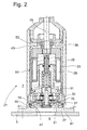
- the damping valve 21 includes, as shown in FIG. 2, an inner housing 23 which is arranged in a tubular outer housing 25, which in turn is connected via fastening means 27, not shown, with the intermediate wall 5 of the damping device 1.
- the damping valve 21 is an adjustable embodiment with a coil 29 whose magnetic force acts on an axially movable valve body 31.
- the valve body 31 can be steplessly or stepped switched and influenced depending on its axial position the passage cross section in at least one flow passage 33.
- the flow passage 33 is connected to an annular space 35 between the outer housing 25 and the inner housing 23, wherein the annular space 35 in turn over a number is connected by connection openings 37 with the working space 7 of the damping device 1.
- the inner housing 23 is above at least one vibration isolating element 39; 41 with the damping device or the outer housing 25 in operative connection.
- a first vibration isolation element 39 is on the cover side, a second vibration isolation element 41 is arranged on the bottom side on the inner housing 23.
- At least one radially effective vibration isolating element 43 is braced between the outer housing 25 and the inner housing 23.
- the cover-side and a radial vibration isolating element 39; 43 made in one piece and form an angular contour.
- the bottom-side vibration isolating element 41 is radially supported on the outside on a projection 45 of the inner housing 23 and on the inside on an edge 47 of the outer housing 25 and consequently can also isolate radial vibrations between the inner housing 23 and the outer housing 25.
- Both axial vibration isolation elements 39; 41 have an annular basic shape, so that on the one hand a cable connection 49 to the coil 29 and on the other hand a large flow cross-section in the outer housing and in the intermediate wall 5 can be used.
- the operating pressure in the piston-side working chamber 9 acts as Axialkraftkomponente on the underside of a valve seat disc 51 of the damping valve 21.
- the cover side 53 of the inner housing 23 is opposed Area also acted upon by an operating pressure of the working space of the damping device.
- the bottom-side vibration isolating element 41 is clamped axially between the valve seat disc 51 and an annular bottom 57 of the outer housing 25. Via the connection opening 37 in the outer housing 25, no leakage current should be able to escape parallel to a valve seat surface 59. Therefore, at least one seal 61 is arranged between the inner housing 23 and the outer housing 25, which prevents leakage parallel to the flow passage 33. When the seal 61 is an O-ring seal, which is also carried out radially elastic limits.
- the entire inner housing 23 is axially loaded.
- force peaks can still occur from the opening or closing valve body 31.
- the two axial vibration isolating elements 39; 41 prevent transmission of the suggestions on the cylinder 3 of the damping device 1 and thus on the vehicle body 19.
- the radially effective vibration isolation elements 43; 41 support the beneficial effect.
Landscapes
- Engineering & Computer Science (AREA)
- General Engineering & Computer Science (AREA)
- Mechanical Engineering (AREA)
- Fluid-Damping Devices (AREA)
- Transition And Organic Metals Composition Catalysts For Addition Polymerization (AREA)
Abstract
Description
- Die Erfindung betrifft eine Dämpfeinrichtung gemäß dem Oberbegriff von Patentanspruch 1.
- Bei Schwingungsdämpfern für Kraftfahrzeuge werden sehr häufig Dämpfventile in einem an einer Kolbenstange befestigten Kolben und/oder in einem zylinderseitigen Bauteil, z. B. einem externen Gehäuse angeordnet. Die an den Dämpfventilen auftretenden Dämpfkräfte werden auf die Kolbenstange oder den Zylinder übertragen, wobei Geräusche ebenfalls weitergeleitet werden. Bei einer Anbindung des Zylinders an ein Fahrzeugrad ist dieser Umstand in der Regel tragbar. Ist das Dämpfventil im Kolben oder in der Kolbenstange angeordnet, dann lässt sich das Geräuschproblem durch eine weiche Lagerung der Kolbenstange zum Fahrzeugaufbau isolieren. Den Fahrzeugaufbau stützende Federkräfte_lassen sich in einem separaten Lager mit einer größeren Steifigkeit abstützen, so dass eine Zweipfadlagerung verwendbar ist. Eine Zweipfadlagerung ist jedoch konstruktiv deutlich aufwändiger als eine Lagerung, die den Schwingungsdämpfer und eine Fahrzeugfeder mit einem einzigen Elastomerelement zum Fahrzeugaufbau isoliert. Bei einer Dämpfeinrichtung mit einem gasförmigen Dämpfmedium lassen sich die Funktionen "Dämpfen" und "Federn" prinzipbedingt nicht trennen, so dass auch eine Zweipfadlagerung der Dämpfeinrichtung keine Abhilfe bringen würde.
- Die
DE 100 017 030 B4 offenbart ein Magnetventil, dessen Ventilkörper eine axial Betriebsbewegung ausführt. An dem beweglichen Ventilkörper sind axial wirksame elastische Noppen ausgeführt, die Anschlaggeräusche in den Endpositionen des Ventilkörpers abfedern sollen, um Anschlaggeräusche zu verhindern. - Aus der
JP 01-242-840 A - Aufgabe der vorliegenden Erfindung ist es das aus dem Stand der Technik bekannte Geräuschproblem zu minimieren.
- Erfindungsgemäß wird die Aufgabe dadurch gelöst, dass das Gehäuse über mindestens ein Schwingungsisolierelement mit der Dämpfeinrichtung in Wirkverbindung steht.
- Geräusche, die vom Dämpfventil verursacht werden oder im Dämpfventil auftreten, werden nicht auf die Dämpfeinrichtung und damit auch nicht auf einen Fahrzeugaufbau übertragen. Durch diese Maßnahme wird ein wesentlicher Komfortgewinn im Fahrzeug erzielt.
- Gemäß einem vorteilhaften Unteranspruch umfasst das Gehäuse ein Innengehäuse und ein Außengehäuse, wobei zwischen dem Innengehäuse und dem Außengehäuse das mindestens eine Schwingungsisolierungselement angeordnet ist.
- In weiterer vorteilhafter Ausgestaltung ist das Innengehäuse über das Außengehäuse mit der Dämpfeinrichtung verbunden. Das Außengehäuse vereinfacht die Vormontage des Dämpfventils und damit die Montage in oder an der Dämpfeinrichtung. Es ist nicht zwingend erforderlich, dass das Außengehäuse das Innengehäuse vollständig umschließt. Das Außengehäuse übernimmt primär die Funktion einer Aufnahme.
- Das Innengehäuse ist mit mindestens einem axial wirksamen Schwingungsisolierelement ausgeführt. Dabei weist das Innengehäuse des Dämpfventils ein deckelseitiges Schwingungsisolierelement auf, so dass die Einflüsse des Betriebsdrucks des Dämpfmediums kompensiert werden.
- Um auch das Rückschwingen des Innengehäuses aufnehmen zu können, weist das Innengehäuse ein bodenseitiges Schwingungsisolierelement auf.
- Zusätzlich kann das Innengehäuse mit einem radial wirksamen Schwingungsisolierelement ausgeführt sein. Insbesondere in der Anwendung bei einer Dämpfeinrichtung in einem Kraftfahrzeug treten nicht nur axial sondern auch radial wirksame Anregungen auf, die von den Schwingungsisolierelementen aufgenommen werden.
- Eine insgesamt kompakte und montagefreundliche Anordnung wird dadurch erreicht, dass das radial wirksame und das axial wirksame Schwingungsisolierelement einteilig ausgeführt sind.
- In weiterer vorteilhafter Ausgestaltung weist das mindestens eine axiale Schwingungsisolierelement eine kreisringförmige Grundform auf. Dadurch entstehen konstruktive Freiheiten für die Gestaltung der Fluidanbindung des Dämpfventils.
- Damit das Schwingungsisolierelement nicht permanent einer einseitigen hohen Belastung durch den Betriebsdruck innerhalb der Dämpfeinrichtung ausgesetzt ist, werden zwei gegenüberliegende Flächen des Innengehäuses vom Betriebsdruck jeweils eines Arbeitsraums der Dämpfeinrichtung beaufschlagt.
- Dafür liegt zwischen dem Innengehäuse und dem Außengehäuse eine Fluidverbindung vor, die einen Arbeitsraum der Dämpfeinrichtung mit einer druckbeaufschlagten Fläche des Innengehäuses verbindet.
- Des Weiteren ist vorgesehen, dass zwischen dem Innengehäuse und dem Außengehäuse mindestens eine Dichtung angeordnet ist, die eine Leckage parallel zum Durchströmungskanal verhindert.
- Anhand der folgenden Figurenbeschreibung soll die Erfindung näher erläutert werden.
- Fig. 1
- Prinzipdarstellung der Dämpfeinrichtung
- Fig. 2
- Dämpfventil als Einzelteil
- Die Fig. 1 zeigt eine Prinzipdarstellung einer Dämpfeinrichtung 1 mit einem Zylinder 3, in dem eine Zwischenwand 5 zwei mit einem gasförmigen Dämpfmedium gefüllte Räume 7; 9 trennt. Im unteren Arbeitsraum 9 ist ein Kolben 11 an einer Kolbenstange 13 axial beweglich geführt und trennt den Arbeitsraum 9 von einem Federraum 15. Die Kolbenstange 13 ist zumindest mittelbar mit einem Fahrzeugrad 17 und der Zylinder 3 mit einem Fahrzeugaufbau 19 verbunden.
- Die besagte Zwischenwand 5 im Zylinder 3 ist mit einem Dämpfventil 21 ausgeführt, dass einen Dämpfmediumaustausch zwischen den beiden Arbeitsräumen 7; 9 beeinflusst. Generell kann die Erfindung auch bei einer Dämpfeinrichtung mit einer deutlich abweichenden Bauweise angewendet werden.
- Das Dämpfventil 21 umfasst, wie die Fig. 2 zeigt, ein Innengehäuse 23, das in einem rohrförmigen Außengehäuse 25 angeordnet ist, das wiederum über nicht dargestellte Befestigungsmittel 27 mit der der Zwischenwand 5 der Dämpfeinrichtung 1 verbunden ist. Bei dem Dämpfventil 21 handelt es sich um eine verstellbare Ausführungsform mit einer Spule 29, deren Magnetkraft auf einen axial beweglichen Ventilkörper 31 wirkt. Der Ventilkörper 31 kann stufenlos oder gestuft schaltbar sein und beeinflusst in Abhängigkeit seiner axialen Position den Durchtrittsquerschnitt in mindestens einem Durchströmungskanal 33. Der Durchströmungskanal 33 ist an einen Ringraum 35 zwischen dem Außengehäuse 25 und dem Innengehäuse 23 angeschlossen, wobei der Ringraum 35 wiederum über eine Anzahl von Anschlussöffnungen 37 mit dem Arbeitsraum 7 der Dämpfeinrichtung 1 verbunden ist.
- Das Innengehäuse 23 steht über mindestens ein Schwingungsisolierelement 39; 41 mit der Dämpfeinrichtung bzw. der Außengehäuse 25 in Wirkverbindung. Es kommen zwei axial wirksame Schwingungsisolierelemente 39; 41 zur Anwendung. Ein erstes Schwingungsisolierelement 39 ist deckelseitig, ein zweites Schwingungsisolierelement 41 ist bodenseitig am Innengehäuse 23 angeordnet.
- Zusätzlich ist mindestens ein radial wirksames Schwingungsisolierelement 43 zwischen dem Außengehäuse 25 dem Innengehäuse 23 verspannt. Dabei sind das deckelseitige und ein radiales Schwingungsisolierelement 39; 43 einteilig ausgeführt und bilden eine winkelförmige Kontur.
- Das bodenseitige Schwingungsisolierelement 41 stützt sich außenseitig radial an einem Überstand 45 des Innengehäuses 23 und innenseitig an einem Rand 47 des Außengehäuse 25 ab und kann folglich auch radiale Schwingungen zwischen dem Innengehäuse 23 und dem Außengehäuse 25 isolieren.
- Beide axialen Schwingungsisolierelemente 39; 41 weisen eine ringförmige Grundform auf, so dass einerseits eine Kabelverbindung 49 zur Spule 29 und andererseits ein großer Strömungsquerschnitt in dem Außengehäuse und in der Zwischenwand 5 nutzbar sind.
- Der Betriebsdruck im kolbenseitigen Arbeitsraum 9 wirkt als Axialkraftkomponente auf die Unterseite einer Ventilsitzscheibe 51 des Dämpfventils 21. Zur Kompensation dieser Druckkraft ist die Deckelseite 53 des Innengehäuses 23 als gegenüberliegende Fläche ebenfalls mit einem Betriebsdruck des Arbeitsraums der Dämpfeinrichtung beaufschlagt. Zwischen dem Innengehäuse und dem Außengehäuse liegt eine Fluidverbindung vor, die den Arbeitsraum 7 oberhalb der Trennwand 5 über den Ringraum 35 und die Anschlussöffnungen 37 mit der Deckelseite 53 des Innengehäuses 23 verbindet.
- Das bodenseitige Schwingungsisolierelement 41 ist axial zwischen der Ventilsitzscheibe 51 und einem ringförmigen Boden 57 des Außengehäuses 25 verspannt. Über die Anschlussöffnung 37 in dem Außengehäuse 25 sollte kein Leckstrom parallel zu einer Ventilsitzfläche 59 entweichen können. Deshalb ist zwischen dem Innengehäuse 23 und dem Außengehäuse 25 mindestens eine Dichtung 61 angeordnet, die eine Leckage parallel zum Durchströmungskanal 33 verhindert. Bei der Dichtung 61 handelt es sich um eine O-Ringdichtung, die in Grenzen ebenfalls radial elastisch ausgeführt ist.
- Bei einer Anströmung des Dämpfventils 21 über den ringförmigen Boden 57 des Außengehäuses 25 wird das gesamte Innengehäuse 23 axial belastet. Zusätzlich können noch Kraftspitzen von dem sich öffnenden oder schließenden Ventilkörper 31 auftreten. Die beiden axialen Schwingungsisolierelemente 39; 41 verhindern eine Übertragung der Anregungen auf den Zylinder 3 der Dämpfeinrichtung 1 und damit auf den Fahrzeugaufbau 19. Die radial wirksamen Schwingungsisolierelemente 43; 41 unterstützen die vorteilhafte Wirkung.
Claims (12)
- Dämpfeinrichtung, umfassend ein Dämpfventil, das ein Gehäuse umfasst, in dem ein Ventilkörper eine Betriebsbewegung ausführt und dabei einen Durchströmkanal zwischen einem Arbeitsraum und einem weiteren Dämpfmedium aufnehmenden Raum beeinflusst, wobei sich eine am Ventilkörper anstehende Druckkraft zumindest mittelbar am Gehäuse des Dämpfventils abstützt,
dadurch gekennzeichnet,
dass das Gehäuse (23; 25) über mindestens ein Schwingungsisolierelement (39; 41; 43) mit der Dämpfeinrichtung (1) in Wirkverbindung steht. - Dämpfeinrichtung nach Anspruch 1,
dadurch gekennzeichnet,
dass das Gehäuse ein Innengehäuse (23) und ein Außengehäuse (25) umfasst, wobei zwischen dem Innengehäuse (23) und dem Außengehäuse (25) das mindestens eine Schwingungsisolierungselement (39; 41; 43) angeordnet ist. - Dämpfeinrichtung nach Anspruch 2,
dadurch gekennzeichnet,
dass das Außengehäuse (25) mit der Dämpfeinrichtung (1) verbunden ist. - Dämpfeinrichtung nach Anspruch 2,
dadurch gekennzeichnet,
dass das Innengehäuse (23) mit mindestens einem axial wirksamen Schwingungsisolierelement (39; 41) ausgeführt ist. - Dämpfeinrichtung nach Anspruch 4,
dadurch gekennzeichnet,
dass das Innengehäuse (23) des Dämpfventils (21) ein deckelseitiges Schwingungsisolierelement (39) aufweist. - Dämpfeinrichtung nach Anspruch 4,
dadurch gekennzeichnet,
dass das Innengehäuse (23) ein bodenseitiges Schwingungsisolierelement (41) aufweist. - Dämpfeinrichtung nach Anspruch 2,
dadurch gekennzeichnet,
dass das Innengehäuse (23) mit einem radial wirksamen Schwingungsisolierelement (43) ausgeführt ist. - Dämpfeinrichtung nach Anspruch 7,
dadurch gekennzeichnet,
dass das radial wirksame und das axial wirksame Schwingungsisolierelement (39; 43) einteilig ausgeführt sind. - Dämpfeinrichtung nach Anspruch 4,
dadurch gekennzeichnet,
dass mindestens ein axiales Schwingungsisolierelement (39; 41) eine kreisringförmige Grundform aufweist. - Dämpfeinrichtung nach Anspruch 1,
dadurch gekennzeichnet,
dass zwei gegenüberliegende Flächen des Innengehäuses (23) vom Betriebsdruck jeweils eines Arbeitsraums (7; 9) der Dämpfeinrichtung (1) beaufschlagt werden. - Dämpfeinrichtung nach Anspruch 10,
dadurch gekennzeichnet,
dass zwischen dem Innengehäuse (23) und dem Außengehäuse (25) eine Fluidverbindung (55) vorliegt, die einen Arbeitsraum (7) der Dämpfeinrichtung (1) mit einer druckbeaufschlagten Fläche (53) des Innengehäuses (23) verbindet. - Dämpfeinrichtung nach Anspruch 2,
dadurch gekennzeichnet,
dass zwischen dem Innengehäuse (23) und dem Außengehäuse (25) mindestens eine Dichtung (61) angeordnet ist, die eine Leckage parallel zum Durchströmungskanal (33) verhindert.
Applications Claiming Priority (1)
| Application Number | Priority Date | Filing Date | Title |
|---|---|---|---|
| DE102006041204A DE102006041204B8 (de) | 2006-09-02 | 2006-09-02 | Dämpfeinrichtung |
Publications (2)
| Publication Number | Publication Date |
|---|---|
| EP1895187A1 true EP1895187A1 (de) | 2008-03-05 |
| EP1895187B1 EP1895187B1 (de) | 2009-08-05 |
Family
ID=38596252
Family Applications (1)
| Application Number | Title | Priority Date | Filing Date |
|---|---|---|---|
| EP07015854A Not-in-force EP1895187B1 (de) | 2006-09-02 | 2007-08-11 | Dämpfeinrichtung |
Country Status (3)
| Country | Link |
|---|---|
| EP (1) | EP1895187B1 (de) |
| AT (1) | ATE438814T1 (de) |
| DE (2) | DE102006041204B8 (de) |
Families Citing this family (1)
| Publication number | Priority date | Publication date | Assignee | Title |
|---|---|---|---|---|
| DE102009011414A1 (de) * | 2009-03-03 | 2010-09-09 | Zf Friedrichshafen Ag | Feder-Dämpfer-Einheit für Fahrwerke von Fahrzeugen |
Citations (4)
| Publication number | Priority date | Publication date | Assignee | Title |
|---|---|---|---|---|
| GB824371A (en) * | 1956-12-06 | 1959-11-25 | Moulton Development Ltd | Improvements in damper valves |
| FR2327450A2 (fr) * | 1975-10-09 | 1977-05-06 | Sirven Jacques | Amortisseur hydraulique de suspension de vehicule |
| JPH01242840A (ja) * | 1988-03-22 | 1989-09-27 | Aisin Seiki Co Ltd | 減衰力調整アクチュエータ |
| DE10017030A1 (de) * | 2000-03-31 | 2001-10-11 | Rausch & Pausch | Magnetventil |
Family Cites Families (2)
| Publication number | Priority date | Publication date | Assignee | Title |
|---|---|---|---|---|
| DE4424436C2 (de) * | 1994-07-12 | 1997-11-27 | Mannesmann Sachs Ag | Absperrventilbaugruppe für einen Schwingungsdämpfer |
| DE10314621B4 (de) * | 2003-04-01 | 2006-03-09 | Carl Freudenberg Kg | Pneumatische Feder-Dämpfer-Einheit |
-
2006
- 2006-09-02 DE DE102006041204A patent/DE102006041204B8/de not_active Expired - Fee Related
-
2007
- 2007-08-11 EP EP07015854A patent/EP1895187B1/de not_active Not-in-force
- 2007-08-11 DE DE502007001226T patent/DE502007001226D1/de active Active
- 2007-08-11 AT AT07015854T patent/ATE438814T1/de not_active IP Right Cessation
Patent Citations (4)
| Publication number | Priority date | Publication date | Assignee | Title |
|---|---|---|---|---|
| GB824371A (en) * | 1956-12-06 | 1959-11-25 | Moulton Development Ltd | Improvements in damper valves |
| FR2327450A2 (fr) * | 1975-10-09 | 1977-05-06 | Sirven Jacques | Amortisseur hydraulique de suspension de vehicule |
| JPH01242840A (ja) * | 1988-03-22 | 1989-09-27 | Aisin Seiki Co Ltd | 減衰力調整アクチュエータ |
| DE10017030A1 (de) * | 2000-03-31 | 2001-10-11 | Rausch & Pausch | Magnetventil |
Also Published As
| Publication number | Publication date |
|---|---|
| DE502007001226D1 (de) | 2009-09-17 |
| ATE438814T1 (de) | 2009-08-15 |
| DE102006041204B8 (de) | 2008-07-24 |
| DE102006041204B3 (de) | 2008-04-10 |
| EP1895187B1 (de) | 2009-08-05 |
Similar Documents
| Publication | Publication Date | Title |
|---|---|---|
| DE4330560C1 (de) | Umschaltbares hydraulisch dämpfendes Lager | |
| DE102011075909A1 (de) | Verstellbare Dämpfventileinrichtung für einen Schwingungsdämpfer | |
| DE19615583A1 (de) | Schwingungsdämpfer mit Vordrosselscheibe | |
| DE4212078A1 (de) | Endlagendämpfer | |
| DE102014210702A1 (de) | Frequenzabhängige Dämpfventilanordnung | |
| DE102014224244A1 (de) | Hydrolager sowie Kraftfahrzeug mit einem derartigen Hydrolager | |
| EP1998070A2 (de) | Schwingungsdämpfer, insbesondere Lenkungsdämpfer | |
| DE102009059234A1 (de) | Adaptives Motorlager | |
| DE19629959A1 (de) | Schwingungsdämpfer mit einem Hydrolager | |
| WO2016206885A1 (de) | Dämpfventileinrichtung | |
| DE10135261C1 (de) | Gasfeder-Dämpfer-Einheit | |
| EP1895187B1 (de) | Dämpfeinrichtung | |
| DE19909914B4 (de) | Hydraulisches Dämpfungselement | |
| DE4445705A1 (de) | Schwingungsdämpfer mit verstellbarer Dämpfkraft | |
| EP1947360A1 (de) | Verstellbares Luftfeder-Dämpfer-Element | |
| DE10321351A1 (de) | Einrichtung zur amplitudenabhängigen Dämpfung von Stößen | |
| WO2003081080A1 (de) | Schaltbares aggregatelager mit hydraulischer dämpfung | |
| EP3436719B1 (de) | Hydrolager | |
| DE10330877A1 (de) | Fahrwerkslager | |
| WO2007065761A1 (de) | Bypass-schaltbares hydrolager mit entkopplungsmembran | |
| DE19833458A1 (de) | Motorlager | |
| DE102005025978B3 (de) | Verstellbarer Schwingungsdämpfer mit gasförmigem Dämpfmedium | |
| DE10355199B4 (de) | Hydrolager, bei dem ein hydraulischer Anschlag durch eine verschiebbare Bodenplatte mittels magnetorheologischer Flüssigkeit steuerbar ist | |
| EP1069339A1 (de) | Hydraulisch dämpfendes Lager | |
| DE102023122423B4 (de) | Dämpfungsventileinrichtung für einen Stoßdämpfer eines Kraftfahrzeugs |
Legal Events
| Date | Code | Title | Description |
|---|---|---|---|
| PUAI | Public reference made under article 153(3) epc to a published international application that has entered the european phase |
Free format text: ORIGINAL CODE: 0009012 |
|
| 17P | Request for examination filed |
Effective date: 20071123 |
|
| AK | Designated contracting states |
Kind code of ref document: A1 Designated state(s): AT BE BG CH CY CZ DE DK EE ES FI FR GB GR HU IE IS IT LI LT LU LV MC MT NL PL PT RO SE SI SK TR |
|
| AX | Request for extension of the european patent |
Extension state: AL BA HR MK YU |
|
| 17Q | First examination report despatched |
Effective date: 20080411 |
|
| AKX | Designation fees paid |
Designated state(s): AT BE BG CH CY CZ DE DK EE ES FI FR GB GR HU IE IS IT LI LT LU LV MC MT NL PL PT RO SE SI SK TR |
|
| GRAP | Despatch of communication of intention to grant a patent |
Free format text: ORIGINAL CODE: EPIDOSNIGR1 |
|
| GRAS | Grant fee paid |
Free format text: ORIGINAL CODE: EPIDOSNIGR3 |
|
| GRAA | (expected) grant |
Free format text: ORIGINAL CODE: 0009210 |
|
| AK | Designated contracting states |
Kind code of ref document: B1 Designated state(s): AT BE BG CH CY CZ DE DK EE ES FI FR GB GR HU IE IS IT LI LT LU LV MC MT NL PL PT RO SE SI SK TR |
|
| REG | Reference to a national code |
Ref country code: GB Ref legal event code: FG4D Free format text: NOT ENGLISH |
|
| REG | Reference to a national code |
Ref country code: CH Ref legal event code: EP |
|
| REG | Reference to a national code |
Ref country code: IE Ref legal event code: FG4D |
|
| REF | Corresponds to: |
Ref document number: 502007001226 Country of ref document: DE Date of ref document: 20090917 Kind code of ref document: P |
|
| LTIE | Lt: invalidation of european patent or patent extension |
Effective date: 20090805 |
|
| PG25 | Lapsed in a contracting state [announced via postgrant information from national office to epo] |
Ref country code: IS Free format text: LAPSE BECAUSE OF FAILURE TO SUBMIT A TRANSLATION OF THE DESCRIPTION OR TO PAY THE FEE WITHIN THE PRESCRIBED TIME-LIMIT Effective date: 20091205 Ref country code: SE Free format text: LAPSE BECAUSE OF FAILURE TO SUBMIT A TRANSLATION OF THE DESCRIPTION OR TO PAY THE FEE WITHIN THE PRESCRIBED TIME-LIMIT Effective date: 20090805 Ref country code: LT Free format text: LAPSE BECAUSE OF FAILURE TO SUBMIT A TRANSLATION OF THE DESCRIPTION OR TO PAY THE FEE WITHIN THE PRESCRIBED TIME-LIMIT Effective date: 20090805 Ref country code: ES Free format text: LAPSE BECAUSE OF FAILURE TO SUBMIT A TRANSLATION OF THE DESCRIPTION OR TO PAY THE FEE WITHIN THE PRESCRIBED TIME-LIMIT Effective date: 20091116 Ref country code: FI Free format text: LAPSE BECAUSE OF FAILURE TO SUBMIT A TRANSLATION OF THE DESCRIPTION OR TO PAY THE FEE WITHIN THE PRESCRIBED TIME-LIMIT Effective date: 20090805 |
|
| NLV1 | Nl: lapsed or annulled due to failure to fulfill the requirements of art. 29p and 29m of the patents act | ||
| PG25 | Lapsed in a contracting state [announced via postgrant information from national office to epo] |
Ref country code: PL Free format text: LAPSE BECAUSE OF FAILURE TO SUBMIT A TRANSLATION OF THE DESCRIPTION OR TO PAY THE FEE WITHIN THE PRESCRIBED TIME-LIMIT Effective date: 20090805 Ref country code: NL Free format text: LAPSE BECAUSE OF FAILURE TO SUBMIT A TRANSLATION OF THE DESCRIPTION OR TO PAY THE FEE WITHIN THE PRESCRIBED TIME-LIMIT Effective date: 20090805 Ref country code: LV Free format text: LAPSE BECAUSE OF FAILURE TO SUBMIT A TRANSLATION OF THE DESCRIPTION OR TO PAY THE FEE WITHIN THE PRESCRIBED TIME-LIMIT Effective date: 20090805 Ref country code: SI Free format text: LAPSE BECAUSE OF FAILURE TO SUBMIT A TRANSLATION OF THE DESCRIPTION OR TO PAY THE FEE WITHIN THE PRESCRIBED TIME-LIMIT Effective date: 20090805 |
|
| BERE | Be: lapsed |
Owner name: ZF FRIEDRICHSHAFEN A.G. Effective date: 20090831 |
|
| REG | Reference to a national code |
Ref country code: IE Ref legal event code: FD4D |
|
| PG25 | Lapsed in a contracting state [announced via postgrant information from national office to epo] |
Ref country code: BG Free format text: LAPSE BECAUSE OF FAILURE TO SUBMIT A TRANSLATION OF THE DESCRIPTION OR TO PAY THE FEE WITHIN THE PRESCRIBED TIME-LIMIT Effective date: 20091105 Ref country code: MC Free format text: LAPSE BECAUSE OF NON-PAYMENT OF DUE FEES Effective date: 20090831 Ref country code: PT Free format text: LAPSE BECAUSE OF FAILURE TO SUBMIT A TRANSLATION OF THE DESCRIPTION OR TO PAY THE FEE WITHIN THE PRESCRIBED TIME-LIMIT Effective date: 20091205 |
|
| PG25 | Lapsed in a contracting state [announced via postgrant information from national office to epo] |
Ref country code: IE Free format text: LAPSE BECAUSE OF FAILURE TO SUBMIT A TRANSLATION OF THE DESCRIPTION OR TO PAY THE FEE WITHIN THE PRESCRIBED TIME-LIMIT Effective date: 20090805 Ref country code: EE Free format text: LAPSE BECAUSE OF FAILURE TO SUBMIT A TRANSLATION OF THE DESCRIPTION OR TO PAY THE FEE WITHIN THE PRESCRIBED TIME-LIMIT Effective date: 20090805 Ref country code: RO Free format text: LAPSE BECAUSE OF FAILURE TO SUBMIT A TRANSLATION OF THE DESCRIPTION OR TO PAY THE FEE WITHIN THE PRESCRIBED TIME-LIMIT Effective date: 20090805 Ref country code: CZ Free format text: LAPSE BECAUSE OF FAILURE TO SUBMIT A TRANSLATION OF THE DESCRIPTION OR TO PAY THE FEE WITHIN THE PRESCRIBED TIME-LIMIT Effective date: 20090805 Ref country code: DK Free format text: LAPSE BECAUSE OF FAILURE TO SUBMIT A TRANSLATION OF THE DESCRIPTION OR TO PAY THE FEE WITHIN THE PRESCRIBED TIME-LIMIT Effective date: 20090805 |
|
| PG25 | Lapsed in a contracting state [announced via postgrant information from national office to epo] |
Ref country code: SK Free format text: LAPSE BECAUSE OF FAILURE TO SUBMIT A TRANSLATION OF THE DESCRIPTION OR TO PAY THE FEE WITHIN THE PRESCRIBED TIME-LIMIT Effective date: 20090805 |
|
| PLBE | No opposition filed within time limit |
Free format text: ORIGINAL CODE: 0009261 |
|
| STAA | Information on the status of an ep patent application or granted ep patent |
Free format text: STATUS: NO OPPOSITION FILED WITHIN TIME LIMIT |
|
| PG25 | Lapsed in a contracting state [announced via postgrant information from national office to epo] |
Ref country code: BE Free format text: LAPSE BECAUSE OF NON-PAYMENT OF DUE FEES Effective date: 20090831 |
|
| 26N | No opposition filed |
Effective date: 20100507 |
|
| PG25 | Lapsed in a contracting state [announced via postgrant information from national office to epo] |
Ref country code: GR Free format text: LAPSE BECAUSE OF FAILURE TO SUBMIT A TRANSLATION OF THE DESCRIPTION OR TO PAY THE FEE WITHIN THE PRESCRIBED TIME-LIMIT Effective date: 20091106 |
|
| PG25 | Lapsed in a contracting state [announced via postgrant information from national office to epo] |
Ref country code: AT Free format text: LAPSE BECAUSE OF NON-PAYMENT OF DUE FEES Effective date: 20090811 |
|
| PG25 | Lapsed in a contracting state [announced via postgrant information from national office to epo] |
Ref country code: IT Free format text: LAPSE BECAUSE OF FAILURE TO SUBMIT A TRANSLATION OF THE DESCRIPTION OR TO PAY THE FEE WITHIN THE PRESCRIBED TIME-LIMIT Effective date: 20090805 |
|
| PG25 | Lapsed in a contracting state [announced via postgrant information from national office to epo] |
Ref country code: MT Free format text: LAPSE BECAUSE OF FAILURE TO SUBMIT A TRANSLATION OF THE DESCRIPTION OR TO PAY THE FEE WITHIN THE PRESCRIBED TIME-LIMIT Effective date: 20090805 Ref country code: LU Free format text: LAPSE BECAUSE OF NON-PAYMENT OF DUE FEES Effective date: 20090811 |
|
| REG | Reference to a national code |
Ref country code: FR Ref legal event code: ST Effective date: 20110502 |
|
| PG25 | Lapsed in a contracting state [announced via postgrant information from national office to epo] |
Ref country code: HU Free format text: LAPSE BECAUSE OF FAILURE TO SUBMIT A TRANSLATION OF THE DESCRIPTION OR TO PAY THE FEE WITHIN THE PRESCRIBED TIME-LIMIT Effective date: 20100206 |
|
| PG25 | Lapsed in a contracting state [announced via postgrant information from national office to epo] |
Ref country code: FR Free format text: LAPSE BECAUSE OF NON-PAYMENT OF DUE FEES Effective date: 20091005 |
|
| PG25 | Lapsed in a contracting state [announced via postgrant information from national office to epo] |
Ref country code: TR Free format text: LAPSE BECAUSE OF FAILURE TO SUBMIT A TRANSLATION OF THE DESCRIPTION OR TO PAY THE FEE WITHIN THE PRESCRIBED TIME-LIMIT Effective date: 20090805 |
|
| PG25 | Lapsed in a contracting state [announced via postgrant information from national office to epo] |
Ref country code: CY Free format text: LAPSE BECAUSE OF FAILURE TO SUBMIT A TRANSLATION OF THE DESCRIPTION OR TO PAY THE FEE WITHIN THE PRESCRIBED TIME-LIMIT Effective date: 20090805 |
|
| REG | Reference to a national code |
Ref country code: CH Ref legal event code: PL |
|
| GBPC | Gb: european patent ceased through non-payment of renewal fee |
Effective date: 20110811 |
|
| PG25 | Lapsed in a contracting state [announced via postgrant information from national office to epo] |
Ref country code: LI Free format text: LAPSE BECAUSE OF NON-PAYMENT OF DUE FEES Effective date: 20110831 Ref country code: CH Free format text: LAPSE BECAUSE OF NON-PAYMENT OF DUE FEES Effective date: 20110831 |
|
| PG25 | Lapsed in a contracting state [announced via postgrant information from national office to epo] |
Ref country code: GB Free format text: LAPSE BECAUSE OF NON-PAYMENT OF DUE FEES Effective date: 20110811 |
|
| PGFP | Annual fee paid to national office [announced via postgrant information from national office to epo] |
Ref country code: DE Payment date: 20140806 Year of fee payment: 8 |
|
| REG | Reference to a national code |
Ref country code: DE Ref legal event code: R119 Ref document number: 502007001226 Country of ref document: DE |
|
| PG25 | Lapsed in a contracting state [announced via postgrant information from national office to epo] |
Ref country code: DE Free format text: LAPSE BECAUSE OF NON-PAYMENT OF DUE FEES Effective date: 20160301 |