EP1894604A2 - Protective clothing - Google Patents
Protective clothing Download PDFInfo
- Publication number
- EP1894604A2 EP1894604A2 EP07016582A EP07016582A EP1894604A2 EP 1894604 A2 EP1894604 A2 EP 1894604A2 EP 07016582 A EP07016582 A EP 07016582A EP 07016582 A EP07016582 A EP 07016582A EP 1894604 A2 EP1894604 A2 EP 1894604A2
- Authority
- EP
- European Patent Office
- Prior art keywords
- gas
- protective suit
- ring
- personal protective
- person
- Prior art date
- Legal status (The legal status is an assumption and is not a legal conclusion. Google has not performed a legal analysis and makes no representation as to the accuracy of the status listed.)
- Granted
Links
- 230000001681 protective effect Effects 0.000 title claims abstract description 123
- 230000029058 respiratory gaseous exchange Effects 0.000 claims abstract description 4
- 230000008878 coupling Effects 0.000 claims description 76
- 238000010168 coupling process Methods 0.000 claims description 76
- 238000005859 coupling reaction Methods 0.000 claims description 76
- 239000000463 material Substances 0.000 claims description 56
- 230000002093 peripheral effect Effects 0.000 claims description 13
- 229920003023 plastic Polymers 0.000 claims description 12
- 239000004753 textile Substances 0.000 claims description 11
- 230000001914 calming effect Effects 0.000 claims description 10
- 231100001261 hazardous Toxicity 0.000 claims description 9
- 239000004033 plastic Substances 0.000 claims description 9
- 230000000903 blocking effect Effects 0.000 claims description 8
- 229920000728 polyester Polymers 0.000 claims description 7
- 239000004814 polyurethane Substances 0.000 claims description 5
- 229920002635 polyurethane Polymers 0.000 claims description 5
- 230000002787 reinforcement Effects 0.000 claims description 5
- 239000013013 elastic material Substances 0.000 claims description 4
- 230000008859 change Effects 0.000 claims description 3
- 239000004744 fabric Substances 0.000 claims description 3
- 239000002184 metal Substances 0.000 claims description 3
- 230000035699 permeability Effects 0.000 claims description 3
- 239000007789 gas Substances 0.000 description 219
- 239000011257 shell material Substances 0.000 description 68
- 239000000126 substance Substances 0.000 description 9
- 239000000383 hazardous chemical Substances 0.000 description 7
- 230000008901 benefit Effects 0.000 description 6
- 230000009467 reduction Effects 0.000 description 6
- 239000011324 bead Substances 0.000 description 5
- 238000004140 cleaning Methods 0.000 description 5
- 238000011109 contamination Methods 0.000 description 5
- 238000007789 sealing Methods 0.000 description 5
- 230000003434 inspiratory effect Effects 0.000 description 4
- 238000004519 manufacturing process Methods 0.000 description 4
- 238000005520 cutting process Methods 0.000 description 3
- 230000006872 improvement Effects 0.000 description 3
- 239000002245 particle Substances 0.000 description 3
- 239000011527 polyurethane coating Substances 0.000 description 3
- 230000001954 sterilising effect Effects 0.000 description 3
- 238000013459 approach Methods 0.000 description 2
- 238000005202 decontamination Methods 0.000 description 2
- 230000003588 decontaminative effect Effects 0.000 description 2
- 230000018044 dehydration Effects 0.000 description 2
- 238000006297 dehydration reaction Methods 0.000 description 2
- 238000011161 development Methods 0.000 description 2
- 238000009434 installation Methods 0.000 description 2
- 238000012423 maintenance Methods 0.000 description 2
- VNWKTOKETHGBQD-UHFFFAOYSA-N methane Chemical compound C VNWKTOKETHGBQD-UHFFFAOYSA-N 0.000 description 2
- 230000035515 penetration Effects 0.000 description 2
- 238000004659 sterilization and disinfection Methods 0.000 description 2
- 206010020751 Hypersensitivity Diseases 0.000 description 1
- 206010052904 Musculoskeletal stiffness Diseases 0.000 description 1
- 241000700605 Viruses Species 0.000 description 1
- 230000006978 adaptation Effects 0.000 description 1
- 239000000853 adhesive Substances 0.000 description 1
- 230000001070 adhesive effect Effects 0.000 description 1
- 208000026935 allergic disease Diseases 0.000 description 1
- 230000007815 allergy Effects 0.000 description 1
- 239000012620 biological material Substances 0.000 description 1
- 230000037237 body shape Effects 0.000 description 1
- 230000000711 cancerogenic effect Effects 0.000 description 1
- 231100000315 carcinogenic Toxicity 0.000 description 1
- 238000013016 damping Methods 0.000 description 1
- 238000013461 design Methods 0.000 description 1
- 230000000249 desinfective effect Effects 0.000 description 1
- 238000006073 displacement reaction Methods 0.000 description 1
- 238000009826 distribution Methods 0.000 description 1
- 239000003814 drug Substances 0.000 description 1
- 230000009977 dual effect Effects 0.000 description 1
- 230000003670 easy-to-clean Effects 0.000 description 1
- 229920001971 elastomer Polymers 0.000 description 1
- 230000007613 environmental effect Effects 0.000 description 1
- 238000001914 filtration Methods 0.000 description 1
- 239000012530 fluid Substances 0.000 description 1
- 230000006870 function Effects 0.000 description 1
- 230000036541 health Effects 0.000 description 1
- 238000009776 industrial production Methods 0.000 description 1
- 230000004941 influx Effects 0.000 description 1
- 239000003345 natural gas Substances 0.000 description 1
- 230000000149 penetrating effect Effects 0.000 description 1
- 229920001296 polysiloxane Polymers 0.000 description 1
- 238000012545 processing Methods 0.000 description 1
- 238000011160 research Methods 0.000 description 1
- 230000035807 sensation Effects 0.000 description 1
- 231100000331 toxic Toxicity 0.000 description 1
- 230000002588 toxic effect Effects 0.000 description 1
Images


Classifications
-
- A—HUMAN NECESSITIES
- A62—LIFE-SAVING; FIRE-FIGHTING
- A62B—DEVICES, APPARATUS OR METHODS FOR LIFE-SAVING
- A62B17/00—Protective clothing affording protection against heat or harmful chemical agents or for use at high altitudes
- A62B17/001—Adaptations for donning, adjusting or increasing mobility, e.g. closures, joints
-
- A—HUMAN NECESSITIES
- A62—LIFE-SAVING; FIRE-FIGHTING
- A62B—DEVICES, APPARATUS OR METHODS FOR LIFE-SAVING
- A62B17/00—Protective clothing affording protection against heat or harmful chemical agents or for use at high altitudes
- A62B17/006—Protective clothing affording protection against heat or harmful chemical agents or for use at high altitudes against contamination from chemicals, toxic or hostile environments; ABC suits
Definitions
- the present invention relates to a personal protective suit for protecting a person in a dangerous environment, comprising an outer shell substantially completely surrounding the person, and gas supply means by means of which a gas can be released inside the outer shell to supply the person with inhalation gas.
- Personal protective suits of this type are known from industrial production as well as from research and are used when a stay of a person to carry out a work or the like is necessary within a particular danger environment in which direct contact of the person with the environment must be avoided.
- a hazard environment is any environment in which hazardous dusts, gases, droplets or the like with a certain level of concentration and / or probability are present, as well as any environment in which there is a danger of coming into contact with these dusts.
- this is thought of premises in which toxic or carcinogenic substances, hazardous biological materials, viruses or similar substances are.
- Particularly well-known personal protective suits are used in laboratories, for example for the production of medicaments or the like, in which the person protected by the protective suit has to deal with the hazardous substances.
- the gas supply means are then connected via a hose to an external gas source of the laboratory, which continuously provides inhaled gas at a predetermined pressure, which is released from the gas supply means inside the personal protection suit.
- the supplied Inhalation gas is partially inhaled by the person and, on the other hand, exits the personal protective suit together with the person's exhalation gas through seams of the suit, crevices around the cuffs and trouser leg ends, through other openings or through special outlet gaps or non-spring-loaded exhalation valves.
- the flow rate of the supplied inhale gas is adjusted to a correspondingly high value in order to ensure a continuous flow of clean natural gas from all openings of the personal protection suit and in this way to prevent the penetration of hazardous substances through openings of the personal protection suit.
- the person in the suit is essentially complete, ie substantially "from head to toe," in a constantly renewing environment of clean breathing gas.
- the outer shell known personal protective suits Although some protection against ingress of hazardous substances, but it is very heavy and relatively stiff, so that the work in such a personal protective suit is associated with high effort and low freedom of movement.
- the comfort of known personal protective suits is additionally affected by the fact that they are generally made only in one or a few clothing sizes and due to the high manufacturing cost of such suits an adaptation to the clothing size of a particular person is not possible or only with great effort.
- conventional personal protective suits are very uncomfortable to wear in one or a few standard sizes, especially for smaller or larger people. Such size differences are particularly noticeable in the hands or feet of people enclosing areas of the protective suit. If several people use one and the same protective suit alternately together, it must be purchased for a suit whose size, in particular in the glove sections or the shoe sections to the size the largest person is adjusted.
- the described personal protective suits also have security-related disadvantages.
- the person wearing the protective suit is protected in the manner described above from direct contact with hazardous substances in the vicinity of the personal protection suit with continuous supply of inhalation gas, but this protection is relatively quickly eliminated if the gas supply is interrupted due to a fault.
- the entry of hazardous substances from the environment into the personal protective suit preventing flow of inhaled gas from the openings of the outer shell abruptly stops and there is a risk that said substances get inside the outer shell before the person concerned the Passenger protection suit filed and entered a safe room or before the person reaches a cleaning chamber or the like in the personal protection suit.
- cost-intensive measures have to be taken to ensure a fail-safe gas supply or a certain security risk must be accepted.
- a personal protective suit for protecting a person in a dangerous environment comprising an outer shell substantially completely surrounding the person, and gas supply means by means of which a gas can be released inside the outer shell around the person supply with inhaled gas, wherein at least one gas outlet valve is provided on the outer shell, which is designed as set to a predetermined target pressure relief valve to set at gas supply an internal pressure inside the personal protection suit substantially to this target pressure.
- the personal protection suit By using a set to a predetermined target pressure relief valve that adjusts an internal pressure of the personal protection suit substantially to this target value with gas supply, it is possible in the personal protection suit according to the invention to maintain a substantially constant and definable in advance target pressure inside the personal protection suit.
- the target pressure to a value that is in particular only slightly greater than the environmental pressure surrounding the personal protective suit, so that the ensured, substantially constant pressure difference between internal pressure and ambient pressure, a readily controllable flow of uncontaminated gas from inside the outer shell through the at least one pressure relief valve takes place.
- the pressure and flow conditions within the personal protection suit can be ensured much more securely and specified more precisely.
- the at least one gas outlet valve switches to a blocking state in which a flow of gas through the gas outlet valve is substantially blocked, and switches when the internal pressure exceeds a second threshold value , in an on-state in which a Outflow of gas from the inside of the personal protection suit is allowed through the gas outlet valve.
- the at least one gas outlet valve in the blocking state when falling below the first threshold pressure measures are taken in the event of a pressure drop within the personal protection suit to prevent further pressure drop of the internal pressure, or at least slowing down significantly.
- the described configuration of the preferred embodiment comes into play in particular in an accident in which the supply of the personal protection suit with inhaled gas is interrupted due to a fault or at least significantly reduced. Due to the outflow of the gas from the gas outlet valves, a fall in the internal pressure will occur in such a case, resulting in a reduction of the outflow velocity of the gas through the at least one gas outlet valve.
- the at least one gas outlet valve switches into the blocking state when it falls below this threshold value and prevents or prevents reduces on the one hand a further pressure drop inside the personal protection suit and on the other hand blocks the entry of contaminated gas from the environment.
- a predetermined overpressure thus remains in such an accident, in order to protect the person in question for a certain period of time in the atmosphere of inspiration gas.
- This period of time may either be sufficient to bridge a temporary interruption of the gas supply or may give the person time to restart the gas supply or to leave the danger zone.
- this period of time can also be set up so that the person concerned has sufficient time to take standard decontamination measures.
- a personal protective suit according to the invention provides a more reliable protection in the danger environment or / and enables the reduction of the effort to ensure an uninterrupted supply of inhaled gas.
- the first threshold pressure is equal to or less than the predetermined target pressure
- the second threshold pressure is equal to or greater than the predetermined target pressure.
- the exhaust valve reliably regulate the internal pressure independently to the target pressure or a control range in the vicinity of the target pressure.
- the first and second threshold pressures are different from each other, it is possible to reduce the number of switching operations of the at least one gas outlet valve.
- a difference between the target pressure and an ambient pressure of the personal protection suit or a difference between the target pressure and a predetermined normal pressure between about 1 mbar (100 Pa) and about 10 mbar (1000 Pa), preferably between about 5 mbar (500 Pa) and about 7 mbar (700 Pa) and more preferably between about 4.0 mbar (400 Pa) and about 4.5 mbar (450 Pa).
- the safety of the personal protection suit according to the invention in particular in the event of a sudden failure of the gas supply, is further increased if, in the blocking state of the at least one gas outlet valve, substantially no gas escapes from the interior of the personal protection suit. In the event of a total failure of the gas supply is then the above-mentioned period of time during which in the personal protective suit, the protective gas atmosphere is maintained, even greater.
- the gas supply means have a backflow blocking device which blocks a flow of gas opposite to the gas supply direction.
- the gas supply means further comprise a provided on the outer shell gas inlet portion which is connected or connectable to an external gas source
- the sudstromsperr Marie may comprise a arranged in the gas inlet portion check valve in a structurally simple embodiment.
- the at least one gas outlet valve may have tamper-evident means which substantially prevent or indicate a change and / or removal of the gas outlet valve.
- tamper-evident means which substantially prevent or indicate a change and / or removal of the gas outlet valve.
- such a tamper-evident means can have at least one detachable engagement projection on which a tool for mounting or / and disassembling the gas outlet valve engages.
- the removable attack projection can be removed after installation of the original gas outlet valve, so that the gas outlet valve can then no longer be removed or replaced without a trace.
- a personal protective suit for protecting a person in a dangerous environment, comprising an outer envelope substantially completely surrounding the person and gas supply means by means of which a gas inside the person
- the outer shell is releasable to supply the person with inhaled gas
- the gas supply has at least one arranged in the head region of the personal protection suit gas discharge opening and wherein the at least one gas discharge opening comprises a flow calming arrangement which distributes the gas over a surface area and / or distributed over several directions releases.
- the gas discharge opening is thus arranged in the head region of the protective suit in which the inhaled gas is significantly required.
- the gas is released via the flow calming arrangement, which calms the flow of gas out of the gas discharge opening.
- the sensation of drafts for the person to be protected is avoided or at least significantly mitigated.
- the distributed release of the gas over a surface area or / and over several directions a direct and punctual influx of a certain area of the person with a relatively high flow rate is avoided and a Cold, stress, dehydration and the like can be prevented.
- the wear comfort of the personal protection suit according to the invention is also significantly improved by this measure.
- the flow calming arrangement comprises an air-permeable solid-state material, in particular a porous or textile or net-like material or the like.
- a material offers a structurally simple way of distributing the gas flow over a surface area or / and over several directions and thus preventing the person from feeling excessive draft.
- such a material contributes to the damping of flow noise and thus further reduces the noise pollution within the personal protection suit.
- the flow calming arrangement may have an overall passage cross section which is larger, in particular more than approximately 2 times larger than the total passage cross section of a gas guide connected to the gas discharge opening. Due to the considerably larger overall passage cross-section, the flow velocity within the flow calming arrangement is significantly reduced and the flow is thus calmed.
- the flow calming arrangement comprises an air-permeable material web, in particular textile or net web, which is arranged inside the outer shell facing the head of the person, and that the gas in a region between the outer shell and the air-permeable material web is introduced so that it is released through the air-permeable material web into the head area of the personal protection suit.
- an air-permeable material web is also of relatively low weight and relatively inexpensive to produce and can be accommodated comfortably in the interior of the personal protection suit without much space.
- the air-permeable material web has a first material web portion, which is arranged facing the neck and the rear head region of the person, and has a second material web portion, which faces the upper head region of the person facing, wherein the first web section has a lower air permeability than the second web section.
- the first material web section is formed from a textile material, in particular a felt material
- the second material band section is formed from a mesh material, for example a plastic mesh or the like.
- a personal protective suit for protecting a person in a dangerous environment, comprising an outer shell substantially entirely surrounding the person, and gas supply means by means of which a gas can be released inside the protective suit to the person with inhalation gas too
- the gas supply means comprise a filter device which filters the gas to be supplied, and wherein the filter device is disposed within the outer shell.
- the filter device By the arrangement of the filter device within the outer shell, the filter device itself is protected against contamination by potentially present in the danger environment hazardous substances. On the one hand, this makes it easier to clean the entire personal protective suit, since the decontamination of the filter device and possibly its associated connection means can be omitted, and on the other hand ensures reliable allocation of the filter device to a specific personal protective suit, so that when leaving the danger environment and cleaning / maintenance of the personal protection suit the filter device is always carried and thus can be reliably maintained or replaced as needed. There are therefore advantages with regard to the overall safety of the personal protection suit and with regard to a reduction of the cleaning / sterilization effort.
- the filter device is mounted on an inner side of the outer shell, so that it is located at a defined position where it is not disturbing especially for the person. If the filter device is accommodated in an openable and closable pocket of the personal protection suit arranged on the inside of the outer shell, the contamination protection of the filter device can be further improved, the filter device remaining accessible for maintenance purposes through a closable pocket opening.
- the gas supply means further includes a gas inlet portion provided on the outer shell which is connected or connectable to an external gas source
- a gas guiding portion must be provided be formed between the gas inlet portion and the filter device substantially gas-tight, to ensure that no unfiltered gas enters the interior of the personal protection suit. Therefore, according to one embodiment, it is proposed that the filter device be adjacent to and connected to the gas inlet section in order to filter the gas supplied by the external gas source. The addressed gas guide between the gas inlet section and the filter device can then be omitted, so that the gas supply means are simplified as a whole.
- a portion from the outlet of the filter device to a gas discharge port for releasing the inhalation gas can be provided without much sealing effort, since a release of filtered gas in the personal protective suit is unproblematic or desired.
- the filter device can even deliver the filtered gas directly into the interior of the personal protection suit.
- the gas supply means have at least one gas discharge opening which discharges the gas into the interior of the personal protection suit, and furthermore have at least one gas guide which connects the filter device to the at least one gas discharge opening. Then discharges the gas guide into the above pocket for receiving the filter device, the bag is an advantageous dual function to go on the one hand receives the filter device for protection against contamination and on the other hand in the closed state, the exiting the filter device filtered gas into the gas conducts and thus forms a connection of the gas guide to the filter device.
- the filter device is operatively connected to the gas inlet portion by means of a releasable coupling operatively substantially gas-tight.
- the releasable coupling then provides on the one hand a gas-tight connection between the gas inlet section and the filter device, on the other hand, can be easily manually released to service / replace the filter device.
- a personal protective suit for protecting a person in a dangerous environment, comprising an outer shell which substantially completely surrounds the person and gas supply means, by means of which a gas inside the person Personal protective suit is releasable to supply the person with inhaled gas
- the gas supply means further comprise a provided on the outer shell gas inlet portion which is connected or connectable to an external gas source, wherein the gas inlet portion has a channel for passing gas, which from an outside the Outer shell extending outer channel piece, an inner channel piece extending within the outer shell and a connecting channel piece which connects the outer channel piece and the inner channel piece to one another, and wherein st the outer channel piece is substantially parallel to a gas inlet portion adjacent portion of the outer shell.
- the problem encountered with known personal protective suits is encountered that an outer channel piece of the gas inlet portion and a piece of tubing connected thereto are pivoted downwards or otherwise towards the personal protective suit due to their own weight or other forces acting in that area.
- Such pivotal movement has resulted in known personal protection suits to a heavy load of the gas inlet portion adjacent portion of the outer shell.
- the outer channel piece is aligned substantially parallel to a section of the outer shell adjacent to the gas inlet section, so that lever forces acting on the gas inlet section become clear be reduced.
- the outer channel piece and thus also a connected thereto hose section in the personal protection suit according to the invention is not disturbing from this, so that the risk of collision of these sections with objects or the like is reduced in the environment.
- the outer channel piece and the inner channel piece may be spaced apart and substantially parallel to the portion of the outer shell adjacent to the gas inlet portion.
- the inner channel piece is not too far away in the direction of the person from, so that the channel piece and an attached element of the personal protection suit (for example, a filter device or the like) can be accommodated in the suit to save space.
- the connecting channel piece has a substantially continuously curved course. In this way, the flow path of the inspiratory gas from the outer channel piece is straightened by the connecting channel piece to the inner channel piece and executed substantially without sharp edges. It has been shown that in this way the flow noise in the region of the gas inlet section can be significantly reduced.
- the gas inlet section comprises an outer housing half containing the outer channel piece and an inner housing half containing the inner channel piece, that the outer shell has a through opening associated with the gas inlet portion and that the two housing half are fastened to each other in such a way that the connecting channel piece the Passage through opening and an edge of the passage opening circumferentially received and sealed between the outer and the inner housing half.
- a personal protective suit for protecting a person in a dangerous environment, comprising an outer shell substantially completely surrounding the person and gas supply means by means of which a gas inside the person Personal protective suit is releasable to provide the person with inhalation gas, wherein the outer shell is formed of a bi-elastic material.
- the outer shell according to the invention provides a significantly improved freedom of movement and a more comfortable seat and thus allows a longer and more comfortable wearing the suit.
- the Bielastiztician the outer shell is usually also accompanied by an improvement in the durability of the suit, as well as a greater number of occurring during the lifetime of the suit kinking movements in the material of the outer shell does not lead to breakage or tearing of the material.
- bi-elastic material has been found to be a polyurethane material with a textile reinforcement.
- the outer shell according to the invention has also been found to be particularly breathable and particularly advantageous to clean / sterilize.
- the textile reinforcement is made of a
- a proportion of polyester in the outer shell material will be between about 40% and about 80%, preferably between about 50% and about 65%, and most preferably about 58%; remaining material content is formed essentially of polyurethane.
- the outer shell may be formed of a material which carries a polyurethane coating on both sides of a polyester knitted fabric.
- the material marketed under the brand name NIMBA-Tex comes into consideration, which is composed of a polyester knit and a proportion of 42% of a polyurethane coating to a proportion of 58%, wherein the polyurethane coating on both sides of the polyester Is arranged.
- NIMBA-Tex was developed and used as a wet protection mat for mattresses, cushions and bedding to protect against moisture and dirt in the care sector.
- NIMBA-Tex is waterproof, chemical-resistant, reliably prevents the passage of harmful substances, but at the same time is breathable, easy to clean, autoclavable, especially at high temperatures, sufficiently tear-resistant, hygiene-tested, recommended for allergy sufferers and durable even with frequent use.
- the material is bi-elastic and relatively light and therefore offers very high wearing comfort.
- a personal protective suit for protecting a person in a dangerous environment, comprising an outer envelope substantially completely surrounding the person and gas supply means by means of which a gas inside the person Personal protective suit can be released to provide the person with inhalation gas, wherein a arranged in the front head portion of the personal protection suit, see-through window is formed of a flexible, transparent plastic material.
- a window of a motor vehicle folding roof has been recognized as an advantageous plastic material.
- such a material is very robust and, on the other hand, offers a low weight and sufficient protection against the harmful substances in question.
- a personal protective suit for protecting a person in a dangerous environment, comprising an outer shell substantially completely surrounding the person, and gas supply means by means of which a gas inside the person Personal protective suit is releasable to supply the person with inhaled gas, wherein the outer shell at least one, in particular of a sleeve portion or a trouser leg portion formed tube portion and at least one hose portion associated with the connector part, in particular in the form of a glove or a shoe, said at least one Connecting part is connected via a releasable coupling operatively substantially gas-tight to the hose portion, and wherein the releasable coupling comprises a first ring, on which an edge portion of the connecting part substantially gas is tightly secured and on the outer periphery of an edge portion of the hose portion along its entire circumference is applied, and comprises a second ring, the first Ring surrounds
- a personal protective suit constructed in this manner offers the possibility of connecting a connection part, in particular gloves and / or shoes, to the personal protective suit by means of a detachable coupling, so that it can be disconnected or coupled in a simple manner if required.
- a connection part in particular gloves and / or shoes
- An essential aspect of the coupling between hose section and connection part according to the invention is that the edge section of the hose section is received and fastened substantially gas-tight between the outer circumference of the first ring and the inner circumference of the second ring. Accordingly, without providing any additional coupling means to the hose portion, the edge portion of the hose portion (i.e., particularly the edge portion of the sleeve portion or the trouser leg portion) can be directly attached to the fitting portion by means of the releasable coupling.
- the coupling of the hose section to the connection part is in a simple operation possible by the edge portion of the tube portion is pulled over the outer circumference of the first ring and then the second ring is pushed over the first ring, so that the tube portion is securely and gas-tightly held between the two rings along its entire circumference.
- the coupling between the rings or the tube section is in particular a frictional coupling.
- Such an O-ring seal can also increase the friction between the 3 elements, first, second ring and tube section, i. ensure the tight fit of these elements to each other, and thus prevent unintentional release of the coupling.
- the O-ring seal extends in an annular groove of the first and / or second ring, so that the O-ring seal can be securely held in its desired position.
- the detachable coupling of such a personal protective suit may also comprise a first ring, around the outer periphery of which a peripheral portion of the connecting part and an edge portion of the hose portion are guided, and a second ring surrounding the first ring, wherein the Edge portion of the connecting part and the edge portion of the hose portion between the outer periphery of the first ring and the inner periphery of the second ring are substantially gas-tight received and fixed.
- the edge portion of the connecting part is pulled around the outer circumference of the first ring and thus releasably attached to the first and second ring.
- one or more O-ring seals can also be provided in the case of a coupling according to the second alternative, which may, if desired, extend for fixing the position in an annular groove of the first and / or the second ring in order to further improve the frictional engagement of the coupling.
- the edge portion of the connection part and the edge portion of the hose portion may overlap each other in the axial direction with selectable degree of overlap, whereby even more secure connection and sealing of the coupling and at the same time a length adjustability of the hose portion is provided.
- the two alternative objects according to the seventh aspect of the invention can be particularly advantageously realized on the same personal protective suit, for example, in the coupling of the shoes, the first ring according to the first alternative is attached to an edge portion of the respective shoe, while in the coupling of Gloves, an edge portion of the gloves according to the second alternative is placed around the first ring and thus clamped with the edge portion of the sleeve portion between the two rings.
- both alternatives may be provided in each case that the first ring has a conical outer peripheral surface, or / and the second ring has a conical inner peripheral surface.
- the inventive coupling according to the seventh aspect of the present invention is also particularly simple and inexpensive to manufacture, when the second ring is formed continuously in the circumferential direction. Advantages in terms of manufacturing costs and in terms of the weight of the coupling and thus the entire personal protective suit are also achieved when the first and / or the second ring of plastic or a light metal is / are.
- the rings of the coupling are particularly easy to produce (eg by turning) and to use, if they have a substantially circular shape.
- the first and the second ring have a shape deviating from a circular shape, in particular substantially oval, a substantially elliptical or substantially egg-shaped ring shape.
- a ring shape corresponds to the natural body shapes of the user in the areas in which the couplings are while wearing the personal protection suit, much better than a circular shape, so that in this way the comfort of the personal protection suit can be further improved.
- the rings thus formed are less bulky and so less disturbing to the user during the work.
- the coupling according to the seventh aspect of the present invention may be configured such that the fitting part and / or the hose portion is secured to the first and / or the second ring by at least one locking screw. In this way it can be prevented with even greater reliability that the coupling dissolves undesirable during work in a hazardous environment and thus causes the risk of contamination.
- such a fixation by means of at least one safety screw can reliably prevent the outer ring from inadvertently from the inner ring is withdrawn when the user stretches or if for other reasons train on the hose section of the personal protection suit is exercised.
- grub screws are preferably used, so that the screws do not protrude or only slightly over a surface of the ring.
- the at least one locking screw passes through a through hole of the second ring in threaded engagement with a thread of the through hole and is screwed against a stop portion of the first ring.
- a further advantageous development of the fixation means of at least one locking screw provides that the abutment portion of the first ring comprises a recess, in particular an annular groove surrounding the first ring, in which the screw in its securing position positively engages.
- the engagement of the screw in such a recess in addition to a possible clamping engagement provides a secure positive locking of the locking screw on the first ring and thus contributes to a further increase in the reliability of the coupling against unintentional release.
- the above-described possibilities of securing the coupling by means of screw locking does not lead to a significant complication of the operation of the coupling.
- the above-described operating steps for closing and opening the coupling remain substantially unchanged, but when closing the coupling after the sliding of the rings on the at least one locking screw is tightened and before opening the coupling, the at least one locking screw is to be solved. If the at least one locking screw is not completely screwed out of its thread during release, then it can be held captive on the second ring until it is used again.
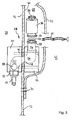
- a personal protective suit according to an embodiment of the present invention is indicated generally at 10. It comprises an outer shell 12, which arms, legs, trunk and a part of the head substantially completely enveloped, a viewing window 14, gloves 16, and shoes 18. About a gas-tight zipper 20, the outer shell 12 can be opened so far that a person on This opening can easily get into the suit 10 and get out of this.
- the outer shell 12 is formed of a polyurethane material having a textile reinforcement of a polyester knit, which under the Designation NIMBA-Tex for applications in the field of care as a bed base is sold.
- the material is cut according to the desired shape of the outer shell 12, sewn and glued and / or welded.
- the viewing window 14 is formed from a flexible, transparent plastic plate, as it also comes as a window material for motor vehicle folding roofs used.
- the viewing window 14 extends over almost the entire head region of the personal protection suit 10, while it has a relatively low weight at the same time. With the outer shell 12, the viewing window is sewn, glued or / and welded.
- the personal protective suit 10 is connected via a hose 22 to an external gas source 24, by means of which the interior of the personal protection suit 10 is supplied with an inhaled gas, so that in the interior of the personal protection suit 10 is a person to be protected substantially completely enveloping atmosphere of inhaled gas created.
- the hose 22 is connected to gas guide means, generally indicated at 26 in FIG. 1, which guide, filter and release the inspiratory gas into the interior of the personal protective suit and release it at a desired location inside the personal protection suit 10.
- the gas guide means 26 comprise a gas inlet section 28 penetrating the outer shell 12 and a filter device 30, a gas guide 32 and a gas release arrangement 34 in the head region of the personal protection suit 10 through the gas inlet portion 28 into the interior of the personal protection suit 10, is filtered in the filter device 30, flows through the gas guide 32 to the gas release assembly 34 and is released there in the interior of the personal protection suit 10 in the head area.
- the personal protective suit 10 has gas outlet sections 36 at at least six rear lateral locations, on which gas outlet valves are to be described later, which, depending on an internal pressure in the personal protective suit 10, gas from the interior into the environment let flow out.
- the gas inlet section 28 has an outer housing half 40 facing the danger environment 38 and an inner housing half 44 facing the interior 42 of the personal protective suit 10, which housing a section of the outer sheath 12 between them.
- the two housing halves 40, 44 attached to each other, so that the intermediate portion of the outer shell 12 is clamped between the housing halves 40, 44 and held.
- connecting channel piece 50 In the clamped between the housing halves 40, 44 portion of the outer shell 12, this has an opening 48 through which a connecting channel piece 50 is guided.
- the connecting channel piece 50 has an approximately S-like shape and merges at its opposite ends into an outer channel piece 52 projecting into the environment 38 or into an inner channel piece 54 projecting into the inner space 42. In this case, both the outer channel piece 52 and the inner channel piece 54 parallel to the gas inlet portion 28 adjacent portion of the outer shell 12th
- the connecting channel piece 50 is indicated only schematically in FIG. 3 by dotted lines and is formed in a suitable manner in the interior of the two housing halves 40, 44.
- so-called labyrinth disks are used, which are used in each case half and when screwing the two Housing halves 40, 44 are assembled to the direction indicated in Figure 3 connecting channel piece 50.
- the surrounding the connecting channel portion opening 48 in the outer shell 12 is thereby fully clamped between the housing halves 40, 44, in particular between adjacent labyrinth disks of the housing halves 40, 44, so that a reliable seal against leakage of gas from the suit 10 and against an intrusion of hazardous substances is ensured.
- a check valve which is disposed at a suitable position in the gas flow path of the gas inlet portion 28 and prevents a flow of gas in a direction from the inner channel piece to the outer channel piece.
- the outer channel piece 52 has a standardized hose coupling 56, to which a gas hose 22 can be connected or disconnected with simple manipulations.
- the inner channel piece 54 has an end flange 58, which is adapted to an end flange 60 of the filter device 30.
- an O-ring seal 64 With the interposition of an O-ring seal 64, the end flange 60 of the filter device 30 can be applied to the end flange 58 of the inner channel piece 54 and the two flanges 58, 60 can then be enclosed by a clamp 66 and coupled to each other in a gastight manner.
- the clamp 66 By means of the clamp 66, the filter device 30 is thus gas-tight and interchangeable connected to the gas inlet portion 28.
- a screw connection can also be used for the coupling between the inner channel piece 54 and the end flange 60.
- the filter device 30 used is preferably a replaceable sterile filter cartridge of the type KA02PFRP8 (manufacturer: Pall GmbH), which has hitherto been developed and marketed for use in laboratory equipment.
- Such filter cartridges 30 have a relatively small size, so that they can be accommodated advantageously in the interior of the personal protection suit 10, and are operable at relatively low pressure. Due to a large flow cross-section within the filter cartridge 30, these filter cartridges 30 operate with respect to conventional filter devices with significantly reduced noise and at the same time allow the reliable filtering of the supplied inhalation gas.
- the inner housing half 44 with the inner channel piece 54 and the filter device 30 with their associated connection means 60, 64, 66 are arranged inside a pocket 68 which is arranged between an inner side 70 of the outer shell 12 and a pocket wall 72 is formed.
- the pocket wall 72 is formed of the same material as the outer shell 12 and is connected via a seam 74 with the inner side 70 of the outer shell 12.
- the pocket 68 can be opened and closed by means of a zipper 76, so that in a normal operating state with the zipper 76 closed, the filter device 30 and the inner housing half 44 are jointly protected against contamination in the pocket 68.
- the pocket 68 merges into the gas guide 32, which leads the gas emerging from the filter device 30 to the gas release arrangement 34 in the head region of the personal protection suit 10.
- the gas guide 32 is constructed of a hose also formed from the material of the outer shell 12, which continues from the pocket wall 72 continuously. By a central seam 80, two opposite walls of the hose of the gas guide 32 are sewn together on the outer shell 12, so that the gas guide 32 is divided into two hoses guided side by side.
- a plastic hose in particular a silicone hose, may be guided in the gas guide 32 and the seam may optionally be dispensed with.
- the gas guide 32 opens in a head region of the personal protection suit 10 in the gas release assembly 34.
- the gas release assembly 34 comprises a substantially rectangular felt web 82 which is sewn along two opposite longitudinal edges 84 on the outer shell 12 and at its the gas guide 32 adjacent longitudinal edge 86 with one of the outer shell 12 removed wall of the gas guide 32 is sewn. Along the remaining edge 90 of the felt web 82 this is sewn to a net 92 of a plastic grid. The edges of the net web 92 not sewn to the felt web 82 are sewn to the outer shell 12.
- the gas release arrangement 34 is arranged on the outer shell 12 such that the felt web 82 faces the rear head region and the neck of a person and the net web 92 faces an upper head region of the person.
- the sections 82 and 92 illustrated in FIG. 4 can also be realized with felt or both with mesh or section 92 can be made with felt and section 82 with mesh.
- gas leaving the filter device 30 flows out of the pocket 68 into the gas guide 32 and from there flows past the felt web 82 and behind the web 92, i.e., downstream of the web. in a flat space between the felt web 82 and the net web 92 on the one hand and the outer shell 12 on the other. Due to the defined air permeability of the felt web 82 and the net web 92, the inhaled gas finally flows through the two webs 82, 92 and is distributed over the surfaces of these webs 82, 92, uniformly and substantially free of draft in the interior of the personal protection suit 10.
- Each gas outlet section 36 has an overpressure valve shown in FIGS. 5a and 5b which depends on a pressure in the interior 42 of the personal protection suit 10 or in dependence on a pressure difference between a person Internal pressure in the interior 42 and an ambient pressure in the environment 38 changes its passage cross-section.
- the pressure relief valve 94 shown in Figures 5a and 5b comprises a cylindrical inner housing 96 which is guided through a correspondingly sized opening 98 in the outer shell 12.
- a flange portion 100 encircling the inner housing 96 rests on the inside of the edge portion of the outer shell 12 that surrounds the opening 98.
- An outer casing 102 is screwed onto the outer periphery of the inner casing 96 from the outer side 38 so that the edge of the opening 98 between a flange portion 103 of the outer casing 102 and the flange portion 100 of the inner casing 96 is substantially gas-tightly clamped and held.
- a valve plate 106 may settle so that it completely closes a gas passage 108 formed in the interior of the inner housing 96.
- the valve disk 106 has at its center a vertically projecting guide pin 110, which is guided in a guide cylinder 114 held by webs 112 of the housing 96 in the center of the gas passage 108.
- a spring 116 is supported on the one hand on an inner side of the outer housing 102 and on the other hand in the center of the valve disk 106. In this case, the spring 116 is biased so that it spans the valve disk from the inside of the outer housing 102 and thus to the ring seal 104 back. The spring 116 thus biases the pressure relief valve 94 in the direction his closed position.
- the pressure relief valve 94 is closed and prevents both leakage of gas from the interior 42 as well as penetration of substances from the environment 38th Wenn Anlagen Continuous supply of inhalation gas in the interior 42 of the personal protection suit 10 an overpressure is established, which exceeds the threshold value, the valve plate 106 lifts against the bias of the spring 116 from the ring seal 104 and allows gas to escape from the personal protection suit 10 through the gas passage 108th , through the gap between the valve plate 106 and ring seal 104 and then through large openings 118 on the circumference of the outer housing 102.
- variable passage cross-section ie a variable gap width between valve plate 106 and ring seal 104, resulting in a fast and self-regulating adjustment of the internal pressure can be done.
- the pressure relief valve 94 closes completely and thus maintains an overpressure in the interior 42 of the personal protection suit 10 corresponding to the bias of the spring 116.
- the flange portion 100 has four cylindrical protrusions 120 to which a corresponding tool for mounting or dismounting the overpressure valve 94 can engage.
- the projections 120 are formed as well as the housing 96 made of plastic and can be easily separated, for example by means of a knife to after installation of the pressure relief valve 94 unauthorized removal of the valve to prevent.
- bores in particular two bores, may be provided on the flange portion 100 as engagement points for a corresponding tool.
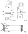
- FIGS. 6 to 10 illustrate a coupling system according to the invention for gloves 16 or shoes 18 on sleeves or trouser legs of the outer shell 12.
- the coupling comprises a first ring 124 with a tapering towards the sleeve 123 outer peripheral surface 126 and a second ring 128 with a to Glove 16 towards the inner circumferential surface 130.
- the first ring 124 has in its outer peripheral surface 126 two mutually parallel circumferential grooves 132, wherein in a circumferential groove 132, an O-ring 134 is inserted.
- the glove 16 For coupling the glove 16 to the sleeve edge 122, the glove 16 is pulled with its opening edge over the first ring 124 until a circumferential bead 136 provided on the opening edge of the glove 16 is inserted into the circumferential groove 132 bearing no O-ring 134.
- an O-ring 134 which is slightly overlapped by the opening edge of the glove 16 may be inserted in the second circumferential groove 132.
- the sleeve edge 122 is at least as far pulled over the first ring 124 until it overlaps the O-ring 134 (see also Figure 7).
- the sleeve edge 122 can also be pulled further over the first ring 124 and, if desired, extend beyond it, so that a desired sleeve length can be adjusted comfortably in this way.
- the ring 128 is pushed in the axial direction from the side of the sleeve over the first ring 124.
- these gradually approach each other when pushing over the two rings 124, 128 and clamp between the opening portion of the glove 16 and the sleeve edge 122 with their respective seals 134, 136 safely .
- the second ring 128 is slid completely over the first ring 124, as illustrated in the right-hand illustration of FIG. 6 and FIG. 7, respectively, the glove 16 and the sleeve of the outer shell 12 are securely and dust-tightly coupled to each other.
- the said steps are respectively reversed, i. the second ring 128 is deported in the direction of the sleeve 123 from the first ring 124 and then the glove 16 and the sleeve edge 122 are detached from the first ring 124.
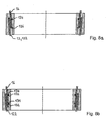
- FIG. 8 a shows a variant of the coupling system according to the invention, in which the circumferential bead 136 of the glove 16 engages in the circumferential groove 132 remote from the glove and the O-ring seal 134 lies in the circumferential groove 132 closer to the glove 16.
- the opening edge of the glove 16 and the sleeve edge 122 are then overlapped between the two rings 124, 128, thereby providing additional sealing of the coupling.
- FIG. 8b shows a further variant of the coupling system according to the invention, in which an engagement of a circumferential bead of the glove 16 in a groove of the first ring is not provided, or the glove 16 does not have a circumferential bead of the type described above.
- an O-ring seal 134 is inserted in both circumferential grooves 132 and both the opening edge of the glove 16 and the sleeve edge 122 overlap both O-ring seals 134.
- the two Fabric layers of the glove 16 and the sleeve edge 122 are thus clamped in closed coupling mainly in two areas, namely in each case between one of the O-ring seals 134 and the inner circumference of the second ring.
- the degree of overlap of the opening edge of the glove 16 and the sleeve edge 122 with each other and / or with the rings 124, 128 in all variants according to Figure 7 or Figures 8a and 8b can be freely selected as needed to change the sleeve length or / and improve the seal on the coupling.
- FIGS. 9 and 10 show a coupling system according to the invention for coupling a shoe 18 to an edge section 138 of a pant leg 139 of the outer shell 12.
- the coupling system has a first ring 124 'with an outer peripheral surface 126' tapering towards the shoe 18 and a second ring 128 '. with an outer circumferential surface 130 'which widens toward the trouser leg 139.
- the first ring 124 ' is formed of a light metal and fixed by means of an adhesive bond to the upper edge portion of the shaft of the shoe 18.
- an O-ring seal 134 ' is an outer circumferential surface 126 'extending circumferential groove 132'.
- FIG. 10 also shows a grub screw 140, which passes through a through hole 142 of the second ring 128 'provided with a matching internal thread.
- a plurality of such grub screws with a suitable through hole for example two, three or four grub screws, are distributed over the circumference of the second ring 128 '.
- the grub screw 140 exerts no pressure on the edge section 138 arranged between the first ring 124 'and the second ring 128'. If the grub screw 140 is screwed into the thread of the passage opening 142 of the second ring 128 ', its end pushes against the first ring 124'.
- the grub screw 140 In the outer peripheral surface 126 'of the first ring 124 'is formed a circumferential engagement groove 144 which receives the male end of the grub screw 140.
- the grub screw 140 In the securing state thus produced, ie the state in which the grub screw 140 is tightened, the grub screw 140 is held securely in the engagement groove 144 both by a clamping force and by a positive locking of the grub screw 140.
- the fuse described by means of grub screws can of course also be used for the coupling of the glove 16 in an analogous manner.
- the trouser leg edge 138 is pulled over the outer circumference 126 'of the first ring 124' at least until the trouser leg edge 138 securely overlaps the O-ring seal 134 '.
- the second ring 128 ' is pushed by the shoe 18 over the first ring 124'.
- the conical outer peripheral surface 128 'of the first ring 124' and the corresponding oppositely conical inner peripheral surface 130 'of the second ring 128' approach each other and clamp between the trouser leg edge 138 safely.
- both described examples of the coupling system according to the invention can be used either for the coupling of a glove on a sleeve as well as for the coupling of a shoe to a trouser leg.
- a permanent reduction of the sleeve or pant leg can be realized in a simple manner by the sleeve or the trouser leg is cut at a suitable location, since the coupling according to the invention at the front edge portion of the sleeve or pant leg, i. at the cutting edge, no special coupling means or the like required.
Abstract
Description
Die vorliegende Erfindung betrifft einen Personenschutzanzug zum Schutz einer Person in einer Gefahrenumgebung, umfassend eine die Person im Wesentlichen vollständig umgebende Außenhülle, sowie Gaszuführungsmittel, mittels welchen ein Gas im Inneren der Außenhülle freisetzbar ist, um die Person mit Einatemgas zu versorgen.The present invention relates to a personal protective suit for protecting a person in a dangerous environment, comprising an outer shell substantially completely surrounding the person, and gas supply means by means of which a gas can be released inside the outer shell to supply the person with inhalation gas.
Personschutzanzüge dieser Art sind aus der industriellen Herstellung sowie aus der Forschung bekannt und kommen zum Einsatz, wenn ein Aufenthalt einer Person zur Ausführung einer Arbeitstätigkeit oder dergleichen innerhalb einer besonderen Gefahrenumgebung notwendig ist, in der ein direkter Kontakt der Person mit der Umgebung vermieden werden muss. Eine solche Gefahrenumgebung ist jede Umgebung, in der gesundheitsgefährdende Stäube, Gase, Tröpfchen oder dergleichen mit einer ein bestimmtes Maß übersteigenden Konzentration oder/und Wahrscheinlichkeit vorhanden sind, sowie auch jede Umgebung, in der die Gefahr besteht, mit diesen Stäuben in Kontakt zu gelangen. Insbesondere wird hierbei an Räumlichkeiten gedacht, in welchen sich toxische oder kanzerogene Stoffe, gesundheitsgefährdende biologische Materialien, Viren oder ähnliche Substanzen befinden.Personal protective suits of this type are known from industrial production as well as from research and are used when a stay of a person to carry out a work or the like is necessary within a particular danger environment in which direct contact of the person with the environment must be avoided. Such a hazard environment is any environment in which hazardous dusts, gases, droplets or the like with a certain level of concentration and / or probability are present, as well as any environment in which there is a danger of coming into contact with these dusts. In particular, this is thought of premises in which toxic or carcinogenic substances, hazardous biological materials, viruses or similar substances are.
Besonders häufig werden bekannte Personenschutzanzüge in Laboren, beispielsweise für die Herstellung von Medikamenten oder dergleichen verwendet, in welchen die durch den Schutzanzug geschützte Person mit den gesundheitsgefährdenden Stoffen zu hantieren hat. Die Gaszuführungsmittel sind dann über einen Schlauch an eine externe Gasquelle des Labors angeschlossen, welche kontinuierlich Einatemgas unter vorbestimmten Druck bereitstellt, das von den Gaszuführungsmitteln im Inneren des Personenschutzanzugs freigesetzt wird. Das zugeführte Einatemgas wird teilweise von der Person eingeatmet und verlässt zum anderen Teil gemeinsam mit Ausatemgas der Person den Personenschutzanzug durch Nahtstellen des Anzugs, Spalte im Bereich der Ärmelenden und der Hosenbeinenden, durch andere Öffnungen oder durch spezielle Auslassspalte oder nicht federbelastete Ausatemventile. Die Strömungsrate des zugeführten Einatemgases wird dabei auf einen entsprechend hohen Wert eingestellt, um eine kontinuierliche Strömung von sauberem Einatemgas aus allen Öffnungen des Personenschutzanzugs heraus sicherzustellen und auf diese Weise ein Eindringen gefährlicher Stoffe durch Öffnungen des Personenschutzanzugs zu verhindern. Auf diese Weise befindet sich die Person in dem Anzug im Wesentlichen vollständig, d.h. im Wesentlichen "von Kopf bis Fuß", in einer sich ständig erneuernden Umgebung aus sauberem Einatemgas.Particularly well-known personal protective suits are used in laboratories, for example for the production of medicaments or the like, in which the person protected by the protective suit has to deal with the hazardous substances. The gas supply means are then connected via a hose to an external gas source of the laboratory, which continuously provides inhaled gas at a predetermined pressure, which is released from the gas supply means inside the personal protection suit. The supplied Inhalation gas is partially inhaled by the person and, on the other hand, exits the personal protective suit together with the person's exhalation gas through seams of the suit, crevices around the cuffs and trouser leg ends, through other openings or through special outlet gaps or non-spring-loaded exhalation valves. The flow rate of the supplied inhale gas is adjusted to a correspondingly high value in order to ensure a continuous flow of clean natural gas from all openings of the personal protection suit and in this way to prevent the penetration of hazardous substances through openings of the personal protection suit. In this way, the person in the suit is essentially complete, ie substantially "from head to toe," in a constantly renewing environment of clean breathing gas.
Für die Sicherheit der Person in einem solchen Personenschutzanzug und damit die Möglichkeit auch in einer Gefahrenumgebung arbeiten und sich bewegen zu können, mussten bislang jedoch eine Reihe von beachtlichen Nachteilen in Kauf genommen werden. So ist zum Beispiel zur Aufrechterhaltung der kontinuierlichen Durchströmung des Anzugs mit sauberem Einatemgas aus Sicherheitsgründen eine relativ hohe Strömungsgeschwindigkeit erforderlich. Die Person ist somit in dem Schutzanzug fortwährend einem beachtlichen Durchzug von Luft ausgesetzt. Diese kontinuierliche Zugluft führt zur Austrocknung der zu schützenden Person, welcher durch hohe Flüssigkeitszufuhr entgegengewirkt werden muss. Zugluft birgt ferner die bekannten Gesundheitsrisiken, denen Personen in einer Zugluftumgebung ausgesetzt sind, wie beispielsweise Verkühlungen, Verspannungen (Genickstarre), etc. Zusätzlich geht mit der hohen Durchströmungsrate von Einatemgas durch den bekannten Personenschutzanzug eine relativ hohe Lärmentwicklung durch Strömungsgeräusche des Gases beim Eintreten in den Personenschutzanzug, beim Freisetzten aus Düsen innerhalb des Anzugs, insbesondere innerhalb des Kopfbereichs, sowie beim Ausströmen des Gases aus dem Personenschutzanzug einher.For the safety of the person in such a personal protective suit and thus the ability to work and move in a hazardous environment, but had to be taken a number of significant disadvantages in purchasing. For example, to maintain the continuous flow of the suit with clean inspiratory gas for safety reasons, a relatively high flow rate is required. The person is thus constantly exposed in the suit to a considerable passage of air. This continuous drafts leads to dehydration of the person to be protected, which must be counteracted by high fluid intake. Draft also involves the known health risks to which persons are exposed in a draft environment, such as colds, tension (neck stiffness), etc. In addition, with the high flow rate of inhale gas through the known personal protective suit, a relatively high noise due to flow noise of the gas entering the Protective suit when released from nozzles within the suit, especially within the head area, as well as the outflow of gas from the protective suit.
Ein weiterer Nachteil bekannter Personenschutzanzüge liegt in dem relativ hohen Aufwand, der zum Reinigen insbesondere zum Sterilisieren und Desinfizieren des Schutzanzugs nach seiner Verwendung in einer Gefahrenumgebung notwendig ist. Die der Gefahrenumgebung zugewandte Außenseite des Personenschutzanzug weist eine Vielzahl von Geräten, Schläuchen Ankopplungssystemen und dergleichen auf, an welchen sich gesundheitsgefährdende Partikel verfangen oder festsetzen können, was eine relativ aufwendige Reinigung bzw. Sterilisierung dieser Elemente notwendig macht. Probleme bereiten dabei insbesondere eine zwischen einer externen Gasquelle und dem Gaseingang des Personenschutzanzugs angeordnete Filtereinrichtung, welche regelmäßig gewechselt und somit zusammen mit ihren zugeordneten Kupplungsmitteln zu dekontaminieren und zu reinigen sind.Another disadvantage of known personal protective suits lies in the relatively high cost, which is necessary for cleaning in particular for sterilizing and disinfecting the protective suit after its use in a hazardous environment. The outside of the personal protective suit facing the danger environment has a multiplicity of devices, hoses, coupling systems and the like, on which harmful particles can catch or settle, which necessitates a relatively complicated cleaning or sterilization of these elements. In particular, problems arise with a filter device arranged between an external gas source and the gas inlet of the personal protection suit, which are changed regularly and are therefore to be decontaminated and cleaned together with their associated coupling means.
Ferner bietet die Außenhülle bekannter Personenschutzanzüge zwar einigen Schutz gegen ein Eindringen gesundheitsgefährdender Stoffe, sie ist jedoch sehr schwer und relativ steif, so dass die Arbeit in einem solchen Personenschutzanzug mit hohem Kraftaufwand und geringer Bewegungsfreiheit verbunden ist. Der Tragekomfort von bekannten Personenschutzanzügen ist zusätzlich dadurch beeinträchtigt, dass diese im Allgemeinen nur in einer oder in wenigen Konfektionsgrößen gefertigt sind und aufgrund der hohen Herstellungskosten solcher Anzüge eine Anpassung an die Konfektionsgröße einer bestimmten Person nicht oder nur mit sehr hohem Aufwand möglich ist. Dementsprechend sind herkömmliche Personenschutzanzüge in einer oder in wenigen Standardgrößen insbesondere für kleinere oder größere Personen sehr unbequem zu tragen. Solchen Größenunterschiede machen sich insbesondere in den die Hände oder Füße der Personen umschließenden Bereichen des Personenschutzanzugs bemerkbar. Sollen mehrere Personen ein und denselben Schutzanzug abwechselnd gemeinsam verwenden, so muss dafür ein Anzug angeschafft werden, dessen Größe insbesondere im Bereich der Handschuhabschnitte oder der Schuhabschnitte an die Größe der größten Person angepasst ist.Furthermore, the outer shell known personal protective suits Although some protection against ingress of hazardous substances, but it is very heavy and relatively stiff, so that the work in such a personal protective suit is associated with high effort and low freedom of movement. The comfort of known personal protective suits is additionally affected by the fact that they are generally made only in one or a few clothing sizes and due to the high manufacturing cost of such suits an adaptation to the clothing size of a particular person is not possible or only with great effort. Accordingly, conventional personal protective suits are very uncomfortable to wear in one or a few standard sizes, especially for smaller or larger people. Such size differences are particularly noticeable in the hands or feet of people enclosing areas of the protective suit. If several people use one and the same protective suit alternately together, it must be purchased for a suit whose size, in particular in the glove sections or the shoe sections to the size the largest person is adjusted.
Die beschriebenen bekannten Personenschutzanzüge weisen jedoch auch sicherheitsrelevante Nachteile auf. So ist die den Schutzanzug tragende Person bei kontinuierlicher Zufuhr von Einatemgas zwar in der oben beschriebenen Weise vor einem direkten Kontakt mit gesundheitsgefährdenden Stoffen in der Umgebung des Personenschutzanzugs geschützt, dieser Schutz fällt jedoch relativ schnell weg, wenn die Gaszufuhr aufgrund einer Störung unterbrochen wird. In einem solchen Fall kommt die das Eintreten von gesundheitsgefährdenden Stoffen aus der Umgebung in den Personenschutzanzug verhindernde Strömung von Einatemgas aus den Öffnungen der Außenhülle schlagartig zum Erliegen und es besteht die Gefahr, dass besagte Stoffe in das Innere der Außenhülle gelangen, bevor die betreffende Person den Personenschutzanzug abgelegt und in einen ungefährdeten Raum gelangt ist bzw. bevor die Person in dem Personenschutzanzug eine Reinigungskammer oder dergleichen erreicht. Im Umkehrschluss müssen somit kostenintensive Maßnahmen zur Sicherstellung einer ausfallsicheren Gasversorgung ergriffen oder ein gewisses Sicherheitsrisiko in Kauf genommen werden.However, the described personal protective suits also have security-related disadvantages. Thus, the person wearing the protective suit is protected in the manner described above from direct contact with hazardous substances in the vicinity of the personal protection suit with continuous supply of inhalation gas, but this protection is relatively quickly eliminated if the gas supply is interrupted due to a fault. In such a case, the entry of hazardous substances from the environment into the personal protective suit preventing flow of inhaled gas from the openings of the outer shell abruptly stops and there is a risk that said substances get inside the outer shell before the person concerned the Passenger protection suit filed and entered a safe room or before the person reaches a cleaning chamber or the like in the personal protection suit. Conversely, therefore, cost-intensive measures have to be taken to ensure a fail-safe gas supply or a certain security risk must be accepted.
Vor dem Hintergrund der beschriebenen Nachteile bekannter Personenschutzanzüge ist es Aufgabe der vorliegenden Erfindung, einen Personenschutzanzug bereitzustellen, welcher einen erhöhten Tragekomfort aufweist und eine flexible Handhabung ermöglicht und welcher gleichzeitig einen sicheren Schutz für die den Personenschutzanzug tragende Person innerhalb einer Gefahrenumgebung bietet.Against the background of the described disadvantages of known personal protective suits, it is an object of the present invention to provide a personal protective suit, which has an increased wearing comfort and allows flexible handling and which at the same time provides a secure protection for the person wearing the protective suit person within a dangerous environment.
Nach einem ersten Aspekt der Erfindung wird diese Aufgabe gelöst durch einen Personenschutzanzug zum Schutz einer Person in einer Gefahrenumgebung, umfassend eine die Person im Wesentlichen vollständig umgebende Außenhülle sowie Gaszuführungsmittel, mittels welchen ein Gas im Inneren der Außenhülle freisetzbar ist, um die Person mit Einatemgas zu versorgen, wobei an der Außenhülle mindestens ein Gasauslassventil vorgesehen ist, welches als auf einen vorbestimmten Solldruck eingestelltes Druckbegrenzungsventil ausgebildet ist, um bei Gaszufuhr einen Innendruck im Inneren des Personenschutzanzugs im Wesentlichen auf diesen Solldruck einzustellen.According to a first aspect of the invention, this object is achieved by a personal protective suit for protecting a person in a dangerous environment, comprising an outer shell substantially completely surrounding the person, and gas supply means by means of which a gas can be released inside the outer shell around the person supply with inhaled gas, wherein at least one gas outlet valve is provided on the outer shell, which is designed as set to a predetermined target pressure relief valve to set at gas supply an internal pressure inside the personal protection suit substantially to this target pressure.
Durch den Einsatz eines auf einen vorbestimmten Solldruck eingestellten Druckbegrenzungsventils, dass bei Gaszufuhr einen Innendruck des Personenschutzanzugs im Wesentlichen auf diesen Sollwert einstellt, ist es in dem erfindungsgemäßen Personenschutzanzug möglich, einen im Wesentlichen konstanten und im Vorfeld definierbaren Solldruck im Inneren des Personenschutzanzugs aufrecht zu erhalten. Um die Person fortwährend in einer schützenden Atmosphäre aus sauberem Einatemgas zu halten ist es somit ausreichend, den Solldruck auf einen Wert einzustellen, der insbesondere nur geringfügig größer ist als der den Personenschutzanzug umgebende Umgebungsdruck, so dass durch den sichergestellten, im Wesentlichen konstanten Druckunterschied zwischen Innendruck und Umgebungsdruck eine gut kontrollierbare Strömung von nicht-kontaminiertem Gas aus dem Inneren der Außenhülle durch das mindestens eine Druckbegrenzungsventil stattfindet. In der Folge lassen sich die Druck- und Strömungsverhältnisse innerhalb des Personenschutzanzugs wesentlich sicherer gewährleisten und genauer festlegen. Insbesondere ist es möglich, die Druck und Strömungsverhältnisse des Gases im Inneren des Personenschutzanzugs nach Maßgabe von Sicherheitserwägungen und Gesichtspunkten des Tragekomforts definiert festzulegen.By using a set to a predetermined target pressure relief valve that adjusts an internal pressure of the personal protection suit substantially to this target value with gas supply, it is possible in the personal protection suit according to the invention to maintain a substantially constant and definable in advance target pressure inside the personal protection suit. Thus, to keep the person continually in a protective atmosphere of clean inspiratory gas, it is thus sufficient to set the target pressure to a value that is in particular only slightly greater than the environmental pressure surrounding the personal protective suit, so that the ensured, substantially constant pressure difference between internal pressure and ambient pressure, a readily controllable flow of uncontaminated gas from inside the outer shell through the at least one pressure relief valve takes place. As a result, the pressure and flow conditions within the personal protection suit can be ensured much more securely and specified more precisely. In particular, it is possible to define the pressure and flow conditions of the gas inside the personal protective suit in accordance with safety considerations and aspects of wearing comfort.
In einer bevorzugten Ausführungsform schaltet das mindestens eine Gasauslassventil dann, wenn der Innendruck des Personenschutzanzugs einen ersten Schwellendruck unterscheidet, in einen Sperrzustand, in welchem ein Strömen von Gas durch das Gasauslassventil im Wesentlichen gesperrt ist, und schaltet dann, wenn der Innendruck einen zweiten Schwellenwert überschreitet, in einen Durchlasszustand, in welchem ein Ausströmen von Gas aus dem Inneren des Personenschutzanzugs durch das Gasauslassventil hindurch zugelassen ist.In a preferred embodiment, when the internal pressure of the personal protective suit distinguishes a first threshold pressure, the at least one gas outlet valve switches to a blocking state in which a flow of gas through the gas outlet valve is substantially blocked, and switches when the internal pressure exceeds a second threshold value , in an on-state in which a Outflow of gas from the inside of the personal protection suit is allowed through the gas outlet valve.
Durch das Schalten des mindestens einen Gasauslassventils in den Sperrzustand bei Unterschreiten des ersten Schwellendrucks werden im Falle eines Druckabfalls innerhalb des Personenschutzanzugs Maßnahmen ergriffen, um einen weiteren Druckabfall des Innendrucks zu verhindern, oder zumindest signifikant zu verlangsamen. Die beschriebene Konfiguration der bevorzugten Ausführungsform kommt insbesondere in einem Störfall zum Tragen, in welchen die Versorgung des Personenschutzanzugs mit Einatemgas aufgrund einer Störung unterbrochen ist oder zumindest signifikant reduziert ist. Durch das Ausströmen des Gases aus den Gasauslassventilen wird es in einem solchen Fall zu einem Abfall des Innendrucks kommen, was zu einer Reduzierung der Ausströmgeschwindigkeit des Gases durch das mindestens eine Gasauslassventil führt. Wird der erste Schwellendruck auf einen Druckwert festgesetzt, unterhalb welchem gesundheitsgefährdende Stoffe bzw. Partikel nicht mehr zuverlässig durch eine Ausströmung des Einatemgases durch das mindestens eine Gasauslassventil ferngehalten werden können, so schaltet das mindestens eine Gasauslassventil bei Unterschreiten dieses Schwellenwerts in den Sperrzustand und verhindert bzw. reduziert so einerseits einen weiteren Druckabfall im Inneren des Personenschutzanzugs und blockiert andererseits den Eintritt von kontaminiertem Gas aus der Umgebung.By switching the at least one gas outlet valve in the blocking state when falling below the first threshold pressure measures are taken in the event of a pressure drop within the personal protection suit to prevent further pressure drop of the internal pressure, or at least slowing down significantly. The described configuration of the preferred embodiment comes into play in particular in an accident in which the supply of the personal protection suit with inhaled gas is interrupted due to a fault or at least significantly reduced. Due to the outflow of the gas from the gas outlet valves, a fall in the internal pressure will occur in such a case, resulting in a reduction of the outflow velocity of the gas through the at least one gas outlet valve. If the first threshold pressure is set to a pressure value below which harmful substances or particles can no longer reliably be kept away by an outflow of the inhaled gas through the at least one gas outlet valve, the at least one gas outlet valve switches into the blocking state when it falls below this threshold value and prevents or prevents reduces on the one hand a further pressure drop inside the personal protection suit and on the other hand blocks the entry of contaminated gas from the environment.
Durch das Schalten des mindestens einen Gasauslassventils in den Sperrzustand bleibt somit in einem solchen Havariefall ein vorbestimmter Überdruck aufrecht erhalten, um die betreffende Person noch für eine gewisse Zeitdauer in der Einatemgas-Atmosphäre zu schützen. Diese Zeitdauer kann entweder ausreichend sein, um eine temporäre Unterbrechung der Gasversorgung zu überbrücken oder kann der Person Zeit geben, die Gasversorgung wieder in Gang zusetzen, oder sich aus der Gefahrenzone zu begeben. Insbesondere kann diese Zeitdauer auch entsprechend so eingerichtet sein, dass der betreffenden Person noch genügend Zeit verbliebt, um übliche Maßnahmen zur Dekontamination zu ergreifen. In der Folge stellt ein solcher erfindungsgemäßer Personenschutzanzug einen zuverlässigeren Schutz in der Gefahrenumgebung bereit oder/und ermöglicht die Reduzierung des Aufwands zur Sicherstellung einer unterbrechungsfreien Versorgung mit Einatemgas.As a result of the switching of the at least one gas outlet valve into the blocking state, a predetermined overpressure thus remains in such an accident, in order to protect the person in question for a certain period of time in the atmosphere of inspiration gas. This period of time may either be sufficient to bridge a temporary interruption of the gas supply or may give the person time to restart the gas supply or to leave the danger zone. In particular, this period of time can also be set up so that the person concerned has sufficient time to take standard decontamination measures. As a result, such a personal protective suit according to the invention provides a more reliable protection in the danger environment or / and enables the reduction of the effort to ensure an uninterrupted supply of inhaled gas.
In der beschriebenen Ausführungsform ist vorzugsweise der erste Schwellendruck gleich dem vorbestimmten Solldruck oder kleiner als dieser und der zweite Schwellendruck ist gleich dem vorbestimmten Solldruck oder größer als dieser. Auf diese Weise kann das Auslassventil den Innendruck zuverlässig selbständig auf den Solldruck bzw. einen Regelungsbereich in der Umgebung des Solldrucks regeln. Wenn sich der erste und der zweite Schwellendruck voneinander unterscheiden, so ist es darüber hinaus möglich, die Anzahl der Schaltvorgänge des mindestens einen Gasauslassventils zu reduzieren.Preferably, in the described embodiment, the first threshold pressure is equal to or less than the predetermined target pressure, and the second threshold pressure is equal to or greater than the predetermined target pressure. In this way, the exhaust valve reliably regulate the internal pressure independently to the target pressure or a control range in the vicinity of the target pressure. In addition, when the first and second threshold pressures are different from each other, it is possible to reduce the number of switching operations of the at least one gas outlet valve.
In einer weiteren bevorzugten Ausführungsform ist vorgesehen, dass eine Differenz zwischen dem Solldruck und einem Umgebungsdruck des Personenschutzanzugs oder eine Differenz zwischen dem Solldruck und einem vorbestimmten Normaldruck zwischen ungefähr 1 mbar (100 Pa) und ungefähr 10 mbar (1000 Pa), vorzugsweise zwischen ungefähr 5 mbar (500 Pa) und ungefähr 7 mbar (700 Pa) und besonders bevorzugt zwischen ungefähr 4,0 mbar (400 Pa) und ungefähr 4,5 mbar (450 Pa) liegt.In a further preferred embodiment it is provided that a difference between the target pressure and an ambient pressure of the personal protection suit or a difference between the target pressure and a predetermined normal pressure between about 1 mbar (100 Pa) and about 10 mbar (1000 Pa), preferably between about 5 mbar (500 Pa) and about 7 mbar (700 Pa) and more preferably between about 4.0 mbar (400 Pa) and about 4.5 mbar (450 Pa).
Mit einer Konfiguration gemäß dieser Ausführungsform ist es nicht nur möglich, die zuzuführende Menge an Einatemgas pro Zeiteinheit zu reduzieren und somit den Gasverbrauch und den Geräteaufwand für die Gaszuführung zu verringern. Der gegenüber bekannten Personenschutzanzügen relativ geringe Sollüberdruck im Inneren des Personenschutzanzugs bietet darüber hinaus entscheidende Vorteile im Hinblick auf den Trage- und Benutzungskomfort des Anzugs. So führt die Druckreduzierung zu einer deutlich reduzierten Durchströmungsrate des Anzugs, wodurch den eingangs beschriebenen Problemen, die mit relativ hohen Durchströmungsraten einhergehen, begegnet werden kann. Insbesondere werden die angesprochenen Belastungen durch Zugluft sowie Gasströmungsgeräusche deutlich reduziert.With a configuration according to this embodiment, not only is it possible to reduce the amount of inhalation gas to be supplied per unit time, and thus to reduce the gas consumption and the equipment cost for the gas supply. The opposite known personal protective suits relatively low target pressure inside the personal protection suit also offers decisive advantages in terms of the wearing and comfort of the suit. So leads the Pressure reduction to a significantly reduced flow rate of the suit, whereby the problems described above, which are associated with relatively high flow rates, can be met. In particular, the mentioned stresses are significantly reduced by drafts and gas flow noise.
Die Sicherheit des erfindungsgemäßen Personenschutzanzugs, insbesondere im Falle eines plötzlichen Ausfalls der Gasversorgung, wird weiter gesteigert, wenn in dem Sperrzustand des mindestens einen Gasauslassventils im Wesentlichen kein Gas aus dem Inneren des Personenschutzanzugs austritt. Im Falle eines völligen Ausfalls der Gasversorgung ist dann die oben erwähnte Zeitspanne, während der in dem Personenschutzanzug die schützende Gasatmosphäre aufrechterhalten bleibt, noch größer.The safety of the personal protection suit according to the invention, in particular in the event of a sudden failure of the gas supply, is further increased if, in the blocking state of the at least one gas outlet valve, substantially no gas escapes from the interior of the personal protection suit. In the event of a total failure of the gas supply is then the above-mentioned period of time during which in the personal protective suit, the protective gas atmosphere is maintained, even greater.
Insbesondere wird in diesem Zusammenhang auch daran gedacht, dass die Gaszuführungsmittel eine Rückstromsperreinrichtung aufweisen, welche eine zur Gaszuführungsrichtung entgegengesetzte Strömung von Gas blockiert. Somit wird auch verhindert, dass im Falle einer Unterbrechung der Gasversorgung Gas durch die Gaszuführungsmittel aus dem Personenschutzanzug austritt. In dem Fall, dass die Gaszuführungsmittel ferner einen an der Außenhülle vorgesehenen Gaseingangsabschnitt aufweisen, welcher an eine externe Gasquelle angeschlossen oder anschließbar ist, kann die Rückstromsperreinrichtung in einer konstruktiv einfachen Ausgestaltung ein in dem Gaseingangsabschnitt angeordnetes Rückschlagventil umfassen.In particular, it is also contemplated in this connection that the gas supply means have a backflow blocking device which blocks a flow of gas opposite to the gas supply direction. Thus, it is also prevented that in case of interruption of the gas supply gas escapes through the gas supply means from the personal protection suit. In the event that the gas supply means further comprise a provided on the outer shell gas inlet portion which is connected or connectable to an external gas source, the Rückstromsperreinrichtung may comprise a arranged in the gas inlet portion check valve in a structurally simple embodiment.
In einer vorteilhaften Variante der Erfindung kann das mindestens eine Gasauslassventil Manipulationssicherungsmittel aufweisen, welche eine Veränderung oder/und Entfernung des Gasauslassventils im Wesentlichen verhindern oder/und anzeigen. Auf diese Weise kann sich eine den Personenschutzanzug zu nutzen beabsichtigende Person vor der Benutzung von dem Vorhandensein eines originalen und somit ordnungsgemäßen Gasauslassventils überzeugen und einer unautorisierten Auswechslung des Gasauslassventils kann vorgebeugt werden.In an advantageous variant of the invention, the at least one gas outlet valve may have tamper-evident means which substantially prevent or indicate a change and / or removal of the gas outlet valve. In this way, a person intending to use the personal protective suit may, prior to use, be aware of the presence of an original and thus proper one Gas outlet valve convince and an unauthorized replacement of the gas outlet valve can be prevented.
In einer besonders einfachen Weise kann ein solches Manipulationssicherungsmittel mindestens einen abtrennbaren Angriffsvorsprung aufweisen, an welchem ein Werkzeug zur Montage oder/und Demontage des Gasauslassventils angreift. Der abtrennbare Angriffsvorsprung lässt sich nach der Montage des originalen Gasauslassventils entfernen, so dass das Gasauslassventil dann nicht mehr spurlos entfernt oder ausgewechselt werden kann.In a particularly simple manner, such a tamper-evident means can have at least one detachable engagement projection on which a tool for mounting or / and disassembling the gas outlet valve engages. The removable attack projection can be removed after installation of the original gas outlet valve, so that the gas outlet valve can then no longer be removed or replaced without a trace.
Nach einem zweiten Aspekt der vorliegenden Erfindung wird die oben genannte Aufgabe gelöst durch einen Personenschutzanzug, insbesondere der vorstehend beschriebenen Art, zum Schutz einer Person in einer Gefahrenumgebung, umfassend eine die Person im Wesentlichen vollständig umgebende Außenhülle sowie Gaszuführungsmittel, mittels welchen ein Gas im Inneren der Außenhülle freisetzbar ist, um die Person mit Einatemgas zu versorgen, wobei, die Gaszuführung mindestens eine im Kopfbereich des Personenschutzanzugs angeordnete Gasabgabeöffnung aufweist und wobei, die mindestens eine Gasabgabeöffnung eine Strömungsberuhigungsanordnung umfasst, welche das Gas über einen Flächenbereich verteilt oder/und über mehrere Richtungen verteilt freisetzt.According to a second aspect of the present invention, the above-mentioned object is achieved by a personal protective suit, in particular of the type described above, for protecting a person in a dangerous environment, comprising an outer envelope substantially completely surrounding the person and gas supply means by means of which a gas inside the person The outer shell is releasable to supply the person with inhaled gas, wherein the gas supply has at least one arranged in the head region of the personal protection suit gas discharge opening and wherein the at least one gas discharge opening comprises a flow calming arrangement which distributes the gas over a surface area and / or distributed over several directions releases.
In einem solchen erfindungsgemäßen Personenschutzanzug ist die Gasabgabeöffnung somit im Kopfbereich des Personenschutzanzugs angeordnet, in welchem das Einatemgas maßgeblich benötigt wird. Dabei wird das Gas über die Strömungsberuhigungsanordnung freigesetzt, welche die Strömung von Gas aus der Gasabgabeöffnung heraus beruhigt. Somit wird das Empfinden von Zugluft für die zu schützende Person vermieden oder zumindest signifikant abgeschwächt. Insbesondere durch die verteilte Freisetzung des Gases über einen Flächenbereich oder/und über mehrere Richtungen wird ein direktes und punktuelles Anströmen eines bestimmten Bereichs der Person mit relativ hoher Strömungsrate vermieden und einer Verkühlung, einer Verspannung, Austrocknen und dergleichen kann vorgebeugt werden. Im Ergebnis wird auch durch diese Maßnahme der Tragekomfort des erfindungsgemäßen Personenschutzanzugs deutlich verbessert.In such a personal protective suit according to the invention, the gas discharge opening is thus arranged in the head region of the protective suit in which the inhaled gas is significantly required. In doing so, the gas is released via the flow calming arrangement, which calms the flow of gas out of the gas discharge opening. Thus, the sensation of drafts for the person to be protected is avoided or at least significantly mitigated. In particular, by the distributed release of the gas over a surface area or / and over several directions, a direct and punctual influx of a certain area of the person with a relatively high flow rate is avoided and a Cold, stress, dehydration and the like can be prevented. As a result, the wear comfort of the personal protection suit according to the invention is also significantly improved by this measure.
In einer bevorzugten Ausführungsform der Erfindung nach dem zweiten Aspekt umfasst die Strömungsberuhigungsanordnung ein luftdurchlässiges Festkörpermaterial, insbesondere ein poröses oder textiles oder netzartiges Material oder dergleichen. Ein solches Material bietet eine konstruktiv einfache Möglichkeit, die Gasströmung über einen Flächenbereich oder/und über mehrere Richtungen zu verteilen und somit das Empfinden eines übermäßigen Luftzugs für die Person zu verhindern. Zusätzlich trägt ein solches Material zur Dämpfung von Strömungsgeräuschen bei und reduziert somit weiter die Lärmbelastung innerhalb des Personenschutzanzugs.In a preferred embodiment of the invention according to the second aspect, the flow calming arrangement comprises an air-permeable solid-state material, in particular a porous or textile or net-like material or the like. Such a material offers a structurally simple way of distributing the gas flow over a surface area or / and over several directions and thus preventing the person from feeling excessive draft. In addition, such a material contributes to the damping of flow noise and thus further reduces the noise pollution within the personal protection suit.
Als alternative oder zusätzliche Möglichkeit, eine beruhigte Strömung von Gas aus der Gasabgabeöffnung zu erreichen, kann die Strömungsberuhigungsanordnung einen Gesamtdurchgangsquerschnitt aufweisen, der größer, insbesondere mehr als ungefähr 2 Mal größer ist als der Gesamtdurchgangsquerschnitt einer an die Gasabgabeöffnung angeschlossenen Gasführung. Durch den beträchtlich größeren Gesamtdurchgangsquerschnitt wird die Strömungsgeschwindigkeit innerhalb der Strömungsberuhigungsanordnung deutlich reduziert und die Strömung somit beruhigt.As an alternative or additional way of achieving a steady flow of gas from the gas discharge opening, the flow calming arrangement may have an overall passage cross section which is larger, in particular more than approximately 2 times larger than the total passage cross section of a gas guide connected to the gas discharge opening. Due to the considerably larger overall passage cross-section, the flow velocity within the flow calming arrangement is significantly reduced and the flow is thus calmed.
In einer weiteren vorteilhaften Ausführungsform der Erfindung ist vorgesehen, dass die Strömungsberuhigungsanordnung eine luftdurchlässige Materialbahn, insbesondere Textil- oder Netzbahn, aufweist, welche im Inneren der Außenhülle dem Kopf der Person zugewandt angeordnet ist, und dass das Gas in einen Bereich zwischen der Außenhülle und der luftdurchlässigen Materialbahn eingeleitet wird, so dass es durch die luftdurchlässige Materialbahn hindurch in den Kopfbereich des Personenschutzanzugs freigesetzt wird. Auf diese Weise kann mit einer konstruktiv einfachen Maßnahme die Freisetzung des Gases über einen sehr großen Flächenbereich bzw. über mehrere Richtungen erreicht werden. Eine solche luftdurchlässige Materialbahn ist ferner von relativ geringem Gewicht und mit relativ geringem Kostenaufwand herstellbar und lässt sich ohne größeren Platzbedarf bequem im Inneren des Personenschutzanzugs unterbringen.In a further advantageous embodiment of the invention, it is provided that the flow calming arrangement comprises an air-permeable material web, in particular textile or net web, which is arranged inside the outer shell facing the head of the person, and that the gas in a region between the outer shell and the air-permeable material web is introduced so that it is released through the air-permeable material web into the head area of the personal protection suit. This way can with a structurally simple measure the release of the gas over a very large area or over several directions can be achieved. Such an air-permeable material web is also of relatively low weight and relatively inexpensive to produce and can be accommodated comfortably in the interior of the personal protection suit without much space.
In einer vorteilhaften Variante der vorstehenden Ausführungsform ist vorgesehen, dass die luftdurchlässige Materialbahn einen ersten Materialbahnabschnitt aufweist, der dem Nacken und dem hinteren Kopfbereich der Person zugewandt angeordnet ist, und einen zweiten Materialbahnabschnitt aufweist, der dem oberen Kopfbereich der Person zugewandt angeordnet ist, wobei der erste Materialbahnabschnitt eine geringere Luftdurchlässigkeit aufweist als der zweite Materialbahnabschnitt. Mit einer solchen Anordnung kann erreicht werden, dass das Einatemgas dem Nacken und dem hinteren Kopfbereich der Person mit einer geringeren Strömungsrate zugeführt wird als dem oberen Kopfbereich. Es hat sich beim praktischen Einsatz einer solchen Anordnung herausgestellt, dass eine solche Verteilung der Luftströmung als besonders angenehm empfunden wird und dass auf diese Weise insbesondere der zugempfindliche Hals- und Nackenbereich vor übermäßiger Zugluft geschützt bleibt. Außerdem wurde erkannt, dass sich eine besonders angenehme Gasatmosphäre im Kopfbereich aufbaut, wenn der erste Materialbahnabschnitt aus einem Textilmaterial, insbesondere einem Filzmaterial gebildet ist, und der zweite Materialbandabschnitt aus einem Netzmaterial, beispielsweise einem Kunststoffgitter oder dergleichen, gebildet ist.In an advantageous variant of the preceding embodiment, it is provided that the air-permeable material web has a first material web portion, which is arranged facing the neck and the rear head region of the person, and has a second material web portion, which faces the upper head region of the person facing, wherein the first web section has a lower air permeability than the second web section. With such an arrangement, it can be achieved that the inspiration gas is supplied to the person's neck and back head area at a lower flow rate than the upper head area. It has been found in the practical use of such an arrangement that such a distribution of the air flow is perceived as particularly pleasant and that in this way, in particular the zuzüpfindliche neck and neck area remains protected from excessive drafts. In addition, it has been recognized that a particularly pleasant gas atmosphere builds up in the head area if the first material web section is formed from a textile material, in particular a felt material, and the second material band section is formed from a mesh material, for example a plastic mesh or the like.
Nach einem dritten Aspekt wird die oben genannte Aufgabe gelöst durch einen Personenschutzanzug, insbesondere der vorstehend beschriebenen Art, zum Schutz einer Person in einer Gefahrenumgebung, umfassend eine die Person im Wesentlichen vollständig umgebende Außenhülle sowie Gaszuführungsmittel, mittels welchen ein Gas im Inneren des Personenschutzanzugs freisetzbar ist, um die Person mit Einatemgas zu versorgen, wobei die Gaszuführungsmittel eine Filtereinrichtung umfassen, welche das zuzuführende Gas filtert, und wobei die Filtereinrichtung innerhalb der Außenhülle angeordnet ist.According to a third aspect, the above-mentioned object is achieved by a personal protective suit, in particular of the type described above, for protecting a person in a dangerous environment, comprising an outer shell substantially entirely surrounding the person, and gas supply means by means of which a gas can be released inside the protective suit to the person with inhalation gas too wherein the gas supply means comprise a filter device which filters the gas to be supplied, and wherein the filter device is disposed within the outer shell.
Durch die Anordnung der Filtereinrichtung innerhalb der Außenhülle ist die Filtereinrichtung selbst vor einer Kontamination durch die in der Gefahrenumgebung möglicherweise vorhandenen gesundheitsgefährdenden Stoffe geschützt. Diese ermöglicht einerseits eine einfachere Reinigung des gesamten Personenschutzanzugs, da die Dekontamination der Filtereinrichtung sowie ggf. ihr zugeordneter Anschlussmittel entfallen kann, und stellt andererseits eine sichere Zuordnung der Filtereinrichtung zu einem bestimmten Personenschutzanzug sicher, so dass beim Verlassen der Gefahrenumgebung und Reinigen/Warten des Personenschutzanzugs die Filtereinrichtung stets mitgeführt wird und somit zuverlässig bei Bedarf gewartet oder ausgewechselt werden kann. Es ergeben sich daher Vorteile im Hinblick auf die Gesamtsicherheit des Personenschutzanzugs sowie im Hinblick auf eine Reduzierung des Reinigungs-/Sterilisationsaufwands.By the arrangement of the filter device within the outer shell, the filter device itself is protected against contamination by potentially present in the danger environment hazardous substances. On the one hand, this makes it easier to clean the entire personal protective suit, since the decontamination of the filter device and possibly its associated connection means can be omitted, and on the other hand ensures reliable allocation of the filter device to a specific personal protective suit, so that when leaving the danger environment and cleaning / maintenance of the personal protection suit the filter device is always carried and thus can be reliably maintained or replaced as needed. There are therefore advantages with regard to the overall safety of the personal protection suit and with regard to a reduction of the cleaning / sterilization effort.
In einer besonders einfachen Ausführungsform ist die Filtereinrichtung an einer Innenseite der Außenhülle angebracht, so dass sie sich an einer definierten Position befindet, an der sie insbesondere für die Person nicht störend ist. Wenn die Filtereinrichtung dabei in einer an der Innenseite der Außenhülle angeordneten, öffen- und schließbaren Tasche des Personenschutzanzugs untergebracht ist, so kann der Kontaminationsschutz der Filtereinrichtung weiter verbessert werden, wobei die Filtereinrichtung zu Wartungszwecken durch eine verschließbare Taschenöffnung zugänglich bleibt.In a particularly simple embodiment, the filter device is mounted on an inner side of the outer shell, so that it is located at a defined position where it is not disturbing especially for the person. If the filter device is accommodated in an openable and closable pocket of the personal protection suit arranged on the inside of the outer shell, the contamination protection of the filter device can be further improved, the filter device remaining accessible for maintenance purposes through a closable pocket opening.
Ist die Filtereinrichtung im Inneren der Außenhülle angeordnet, so muss in einem Fall, dass die Gaszuführungsmittel ferner einen an der Außenhülle vorgesehenen Gaseingangsabschnitt aufweisen, welcher an einer externen Gasquelle angeschlossen oder anschließbar ist, ein Gasführungsabschnitt zwischen dem Gaseingangsabschnitt und der Filtereinrichtung im Wesentlichen gasdicht ausgebildet sein, um sicherzustellen, dass kein ungefiltertes Gas in das Innere des Personenschutzanzugs gelangt. Gemäß einer Ausführungsform wird daher vorgeschlagen, dass die Filtereinrichtung dem Gaseingangsabschnitt benachbart und an diesen angeschlossen ist, um das von der externen Gasquelle zugeführte Gas zu filtern. Die angesprochene Gasführung zwischen Gaseingangsabschnitt und Filtereinrichtung kann dann wegfallen, so dass die Gaszuführungsmittel insgesamt vereinfacht werden. Ein Abschnitt von dem Ausgang der Filtereinrichtung zu einer Gasabgabeöffnung zum Freisetzen des Einatemgases kann ohne größeren Dichtungsaufwand bereitgestellt werden, da eine Freisetzung von gefiltertem Gas in dem Personenschutzanzug unproblematisch bzw. gewünscht ist. In einer besonders einfachen Variante kann die Filtereinrichtung das gefilterte Gas sogar direkt in das Innere des Personenschutzanzugs abgeben.When the filter device is disposed inside the outer shell, in a case that the gas supply means further includes a gas inlet portion provided on the outer shell which is connected or connectable to an external gas source, a gas guiding portion must be provided be formed between the gas inlet portion and the filter device substantially gas-tight, to ensure that no unfiltered gas enters the interior of the personal protection suit. Therefore, according to one embodiment, it is proposed that the filter device be adjacent to and connected to the gas inlet section in order to filter the gas supplied by the external gas source. The addressed gas guide between the gas inlet section and the filter device can then be omitted, so that the gas supply means are simplified as a whole. A portion from the outlet of the filter device to a gas discharge port for releasing the inhalation gas can be provided without much sealing effort, since a release of filtered gas in the personal protective suit is unproblematic or desired. In a particularly simple variant, the filter device can even deliver the filtered gas directly into the interior of the personal protection suit.
Vorzugsweise weisen jedoch die Gaszuführungsmittel mindestens eine Gasabgabeöffnung auf, welche das Gas in das Innere des Personenschutzanzugs abgibt, und weisen ferner mindestens eine Gasführung auf, welche die Filtereinrichtung mit der mindestens einen Gasabgabeöffnung verbindet. Mündet dann die Gasführung in die oben genannte Tasche zur Aufnahme der Filtereinrichtung, so kommt der Tasche eine vorteilhafte Doppelfunktion dahin gehend zu, dass sie einerseits die Filtereinrichtung zum Schutz gegen Kontamination aufnimmt und andererseits im geschlossenen Zustand das aus der Filtereinrichtung austretende gefilterte Gas in die Gasführung leitet und somit einen Anschluss der Gasführung an die Filtereinrichtung bildet.Preferably, however, the gas supply means have at least one gas discharge opening which discharges the gas into the interior of the personal protection suit, and furthermore have at least one gas guide which connects the filter device to the at least one gas discharge opening. Then discharges the gas guide into the above pocket for receiving the filter device, the bag is an advantageous dual function to go on the one hand receives the filter device for protection against contamination and on the other hand in the closed state, the exiting the filter device filtered gas into the gas conducts and thus forms a connection of the gas guide to the filter device.
Um die Auswechselung der Filtereinrichtung weiter zu erleichtern, wird zudem daran gedacht, dass die Filtereinrichtung an dem Gaseingangsabschnitt mittels einer lösbaren Kopplung betriebsmäßig im Wesentlichen gasdicht angeschlossen ist. Die lösbare Kopplung stellt dann einerseits eine gasdichte Verbindung zwischen dem Gaseingangsabschnitt und der Filtereinrichtung bereit und lässt sich andererseits leicht manuell lösen, um die Filtereinrichtung zu warten/ zu ersetzen.In order to facilitate the replacement of the filter device further, it is also contemplated that the filter device is operatively connected to the gas inlet portion by means of a releasable coupling operatively substantially gas-tight. The releasable coupling then provides on the one hand a gas-tight connection between the gas inlet section and the filter device, on the other hand, can be easily manually released to service / replace the filter device.
Gemäß einem vierten Aspekt der vorliegenden Erfindung die oben genannte Aufgabe gelöst durch einen Personenschutzanzug, insbesondere gemäß der vorstehend beschriebenen Art, zum Schutz einer Person in einer Gefahrenumgebung, umfassend eine die Person im Wesentlichen vollständig umgebende Außenhülle sowie Gaszuführungsmittel, mittels welchen ein Gas im Inneren des Personenschutzanzugs freisetzbar ist, um die Person mit Einatemgas zu versorgen, wobei die Gaszuführungsmittel ferner einen an der Außenhülle vorgesehenen Gaseingangsabschnitt aufweisen, welcher an eine externe Gasquelle angeschlossen oder anschließbar ist, wobei der Gaseingangsabschnitt einen Kanal zum Durchleiten von Gas aufweist, der aus einem außerhalb der Außenhülle verlaufenden äußeren Kanalstück, einem innerhalb der Außenhülle verlaufenden inneren Kanalstück sowie einem das äußere Kanalstück und das innere Kanalstück miteinander verbindenden Verbindungskanalstück gebildet ist, und wobei zumindest das äußere Kanalstück im Wesentlichen parallel zu einem dem Gaseingangsabschnitt benachbarten Abschnitt der Außenhülle verläuft.According to a fourth aspect of the present invention, the above-mentioned object is achieved by a personal protective suit, in particular of the type described above, for protecting a person in a dangerous environment, comprising an outer shell which substantially completely surrounds the person and gas supply means, by means of which a gas inside the person Personal protective suit is releasable to supply the person with inhaled gas, wherein the gas supply means further comprise a provided on the outer shell gas inlet portion which is connected or connectable to an external gas source, wherein the gas inlet portion has a channel for passing gas, which from an outside the Outer shell extending outer channel piece, an inner channel piece extending within the outer shell and a connecting channel piece which connects the outer channel piece and the inner channel piece to one another, and wherein st the outer channel piece is substantially parallel to a gas inlet portion adjacent portion of the outer shell.
Durch eine solche Konfiguration des Gaseingangsabschnitts wird dem bei bekannten Personenschutzanzügen auftretenden Problem begegnet, dass ein äußeres Kanalstück des Gaseingangsabschnitts sowie ein daran angeschlossenes Schlauchstück aufgrund ihres eigenen Gewichts oder aufgrund anderer in diesem Bereich wirkender Kräfte nach unten oder in anderer Weise zum Personenschutzanzug hin verschwenkt werden. Eine solche Schwenkbewegung hat bei bekannten Personenschutzanzügen zu einer starken Belastung des dem Gaseingangsabschnitt benachbarten Abschnitts der Außenhülle geführt. Erfindungsgemäß ist dagegen das äußere Kanalstück im Wesentlichen parallel zu einem dem Gaseingangsabschnitt benachbarten Abschnitt der Außenhülle ausgerichtet, so dass auf den Gaseingangsabschnitt wirkende Hebelkräfte deutlich reduziert werden. Darüber hinaus steht das äußere Kanalstück und somit auch ein daran angeschlossener Schlauchabschnitt in dem erfindungsgemäßen Personenschutzanzug nicht störend von diesem ab, so dass die Gefahr einer Kollision dieser Abschnitte mit Gegenständen oder dergleichen in der Umgebung reduziert ist.By such a configuration of the gas inlet portion, the problem encountered with known personal protective suits is encountered that an outer channel piece of the gas inlet portion and a piece of tubing connected thereto are pivoted downwards or otherwise towards the personal protective suit due to their own weight or other forces acting in that area. Such pivotal movement has resulted in known personal protection suits to a heavy load of the gas inlet portion adjacent portion of the outer shell. According to the invention, on the other hand, the outer channel piece is aligned substantially parallel to a section of the outer shell adjacent to the gas inlet section, so that lever forces acting on the gas inlet section become clear be reduced. In addition, the outer channel piece and thus also a connected thereto hose section in the personal protection suit according to the invention is not disturbing from this, so that the risk of collision of these sections with objects or the like is reduced in the environment.
Gemäß einer vorteilhaften Ausführungsform des Personenschutzanzugs des vierten Aspekts können das äußere Kanalstück und das innere Kanalstück im Abstand voneinander und im Wesentlich parallel zu dem dem Gaseingangsabschnitt benachbarten Abschnitt der Außenhülle verlaufen. Somit steht auch das innere Kanalstück nicht zu weit in Richtung zu der Person hin ab, so dass das Kanalstück sowie ein daran angeschlossenes Element des Personenschutzanzugs (beispielsweise eine Filtereinrichtung oder dergleichen) platzsparend in dem Anzug untergebracht werden können.According to an advantageous embodiment of the personal protective suit of the fourth aspect, the outer channel piece and the inner channel piece may be spaced apart and substantially parallel to the portion of the outer shell adjacent to the gas inlet portion. Thus, the inner channel piece is not too far away in the direction of the person from, so that the channel piece and an attached element of the personal protection suit (for example, a filter device or the like) can be accommodated in the suit to save space.
Gemäß einer vorteilhaften Weiterbildung ist vorgesehen, dass das Verbindungskanalstück einen im Wesentlichen stufenlos gekrümmten Verlauf aufweist. Auf diese Weise ist der Strömungsweg des Einatemgases von dem äußeren Kanalstück durch das Verbindungskanalstück zu dem inneren Kanalstück begradigt und im Wesentlichen ohne scharfe Kanten ausgeführt. Es hat sich gezeigt, dass auf diese Weise die Strömungsgeräusche im Bereich des Gaseingangsabschnitts deutlich reduziert werden können.According to an advantageous development it is provided that the connecting channel piece has a substantially continuously curved course. In this way, the flow path of the inspiratory gas from the outer channel piece is straightened by the connecting channel piece to the inner channel piece and executed substantially without sharp edges. It has been shown that in this way the flow noise in the region of the gas inlet section can be significantly reduced.
Um eine konstruktiv einfache, jedoch zuverlässig gasdichte Durchführung des Gaswegs durch die Außenhülle des Personenschutzanzugs zu ermöglichen wird ferner vorgeschlagen, dass der Gaseingangsabschnitt eine das äußere Kanalstück enthaltende äußeren Gehäusehälfte und eine das innere Kanalstück enthaltende innere Gehäusehälfte aufweist, dass die Außenhülle eine dem Gaseingangsabschnitt zugeordnete Durchgangsöffnung aufweist und dass die beiden Gehäusehälfte derart aneinander befestigt sind, dass das Verbindungskanalstück die Durchgangsöffnung durchsetzt und ein Rand der Durchgangsöffnung umlaufend zwischen der äußeren und der inneren Gehäusehälfte aufgenommen und abgedichtet ist.In order to enable a structurally simple, but reliable gas-tight implementation of the gas path through the outer shell of the personal protection suit, it is further proposed that the gas inlet section comprises an outer housing half containing the outer channel piece and an inner housing half containing the inner channel piece, that the outer shell has a through opening associated with the gas inlet portion and that the two housing half are fastened to each other in such a way that the connecting channel piece the Passage through opening and an edge of the passage opening circumferentially received and sealed between the outer and the inner housing half.
Gemäß einem fünften Aspekt der vorlegenden Erfindung wird die oben genannte Aufgabe gelöst durch einen Personenschutzanzug, insbesondere der vorstehend beschriebenen Art, zum Schutz einer Person in einer Gefahrenumgebung, umfassend eine die Person im Wesentlichen vollständig umgebende Außenhülle sowie Gaszuführungsmittel, mittels welchen ein Gas im Inneren des Personenschutzanzugs freisetzbar ist, um die Person mit Einatemgas zu versorgen, wobei die Außenhülle aus einem bielastischen Material gebildet ist.According to a fifth aspect of the present invention, the above-mentioned object is achieved by a personal protective suit, in particular of the type described above, for protecting a person in a dangerous environment, comprising an outer shell substantially completely surrounding the person and gas supply means by means of which a gas inside the person Personal protective suit is releasable to provide the person with inhalation gas, wherein the outer shell is formed of a bi-elastic material.
Im praktischen Einsatz eines solchen Personenschutzanzugs mit einer aus bielastischem Material gebildeten Außenhülle hat sich eine überraschende und signifikante Verbesserung des allgemeinen Tragekomforts des Anzugs herausgestellt. Die erfindungsgemäße Außenhülle stellt eine deutlich verbesserte Bewegungsfreiheit sowie einen bequemeren Sitz bereit und ermöglicht somit ein längeres und bequemeres Tragen des Anzugs. Die Bielastizität der Außenhülle geht in der Regel außerdem mit einer Verbesserung der Haltbarkeit des Anzugs einher, da auch eine größere Anzahl von im Laufe der Lebenszeit des Anzugs stattfindenden Knickbewegungen im Material der Außenhülle nicht zu einem Brechen oder Einreißen des Materials führen.In the practical use of such a personal protective suit with an outer shell formed from bielastic material, a surprising and significant improvement of the overall wearing comfort of the suit has been found. The outer shell according to the invention provides a significantly improved freedom of movement and a more comfortable seat and thus allows a longer and more comfortable wearing the suit. The Bielastizität the outer shell is usually also accompanied by an improvement in the durability of the suit, as well as a greater number of occurring during the lifetime of the suit kinking movements in the material of the outer shell does not lead to breakage or tearing of the material.
Als besonders geeignet hat sich als bielastisches Material ein Polyurethan-Material mit einer Textilverstärkung herausgestellt. Neben den an Materialien für Personenschutzanzüge allgemein gestellten Anforderungen, gesundheitsgefährdende Substanzen und Partikel zu blockieren, hat sich die erfindungsgemäße Außenhülle zudem als besonders atmungsaktiv und als besonders vorteilhaft zu reinigen/zu sterilisieren herausgestellt.Particularly suitable as bi-elastic material has been found to be a polyurethane material with a textile reinforcement. In addition to the general requirements for materials for personal protective suits to block harmful substances and particles, the outer shell according to the invention has also been found to be particularly breathable and particularly advantageous to clean / sterilize.
In einer vorteilhaften Ausführungsform ist die Textilverstärkung aus einem Polyester-Gewirk gebildet, wobei insbesondere daran gedacht wird, dass ein Anteil an Polyester am Material der Außenhülle zwischen ungefähr 40% und ungefähr 80%, vorzugsweise zwischen ungefähr 50% und ungefähr 65% und besonders bevorzugt bei ungefähr 58% liegt, und dass der verbleibende Materialanteil im Wesentlichen aus Polyurethan gebildet ist.In an advantageous embodiment, the textile reinforcement is made of a In particular, it is contemplated that a proportion of polyester in the outer shell material will be between about 40% and about 80%, preferably between about 50% and about 65%, and most preferably about 58%; remaining material content is formed essentially of polyurethane.
Besonders vorteilhaft kann die Außenhülle aus einem Material gebildet sein, welches auf beiden Seiten eines Polyester-Gewirks eine Polyurethan-Beschichtung trägt. Hier kommt speziell das unter der Markenbezeichnung NIMBA-Tex vertriebene Material in Betracht, welches zu einem Anteil von 58% aus einem Polyester-Gewirk und zum einem Anteil von 42% aus einer Polyurethan-Beschichtung gebildet ist, wobei die Polyurethan-Beschichtung beidseitig des Polyester-Gewirks angeordnet ist. NIMBA-Tex wurde entwickelt und eingesetzt als Nässeschutzbahn für Matratzen, Kissen und Bettausstattungen zum Schutz gegen Nässe und Verschmutzung im Bereich der Pflege. NIMBA-Tex ist wasserdicht, chemikalienfest, verhindert zuverlässig den Durchgang gesundheitsgefährdender Substanzen, ist jedoch gleichzeitig atmungsaktiv, leicht zu reinigen, insbesondere bei hohen Temperaturen autoklavierbar, ausreichend reißfest, hygienebegutachtet, für Allergiker empfohlen und auch bei häufiger Benutzung langlebig. Als entscheidender Vorteil ist das Material bielastisch und relativ leicht und bietet demnach sehr hohen Tragekomfort.Particularly advantageously, the outer shell may be formed of a material which carries a polyurethane coating on both sides of a polyester knitted fabric. In particular, the material marketed under the brand name NIMBA-Tex comes into consideration, which is composed of a polyester knit and a proportion of 42% of a polyurethane coating to a proportion of 58%, wherein the polyurethane coating on both sides of the polyester Is arranged. NIMBA-Tex was developed and used as a wet protection mat for mattresses, cushions and bedding to protect against moisture and dirt in the care sector. NIMBA-Tex is waterproof, chemical-resistant, reliably prevents the passage of harmful substances, but at the same time is breathable, easy to clean, autoclavable, especially at high temperatures, sufficiently tear-resistant, hygiene-tested, recommended for allergy sufferers and durable even with frequent use. As a decisive advantage, the material is bi-elastic and relatively light and therefore offers very high wearing comfort.
Nach einem sechsten Aspekt der vorliegenden Erfindung wird die oben genannte Aufgabe gelöst durch einen Personenschutzanzug, insbesondere der vorstehend beschriebenen Art, zum Schutz einer Person in einer Gefahrenumgebung, umfassend eine die Person im Wesentlichen vollständig umgebende Außenhülle sowie Gaszuführungsmittel, mittels welchen ein Gas im Inneren des Personenschutzanzugs freisetzbar ist, um die Person mit Einatemgas zu versorgen, wobei ein im vorderen Kopfbereich des Personenschutzanzugs angeordnetes Durchsichtfenster, aus einem flexiblen, transparenten Kunststoffmaterial gebildet ist.According to a sixth aspect of the present invention, the above-mentioned object is achieved by a personal protective suit, in particular of the type described above, for protecting a person in a dangerous environment, comprising an outer envelope substantially completely surrounding the person and gas supply means by means of which a gas inside the person Personal protective suit can be released to provide the person with inhalation gas, wherein a arranged in the front head portion of the personal protection suit, see-through window is formed of a flexible, transparent plastic material.
Durch den Einsatz eines Kunststoffmaterials als Material für das Durchsichtfenster kann eine deutliche Gewichtsreduzierung des Durchsichtsfenster und somit des gesamten Personenschutzanzugs erreicht werden, womit insbesondere eine Verbesserung des Tragekomforts des Personenschutzanzugs einhergeht Andererseits ist es möglich, die Größe des Durchsichtfensters bei akzeptierbarer Zunahme des Gesamtgewichts deutlich zu vergrößern und somit das Sichtfeld für die zu schützende Person zu vergrößern, was ebenfalls mit einer Steigerung des Tragekomforts verbunden ist.By using a plastic material as the material for the see-through window, a significant reduction in weight of the see-through window and thus the entire personal protection suit can be achieved, which in particular an improvement in wearing comfort of personal protection suit goes on the other hand, it is possible to increase the size of the see-through window with an acceptable increase in the total weight significantly and thus to increase the field of view for the person to be protected, which is also associated with an increase in wearing comfort.
Es wurde insbesondere die Verwendung eines Fensters eines Kraftfahrzeug-Faltdachs als vorteilhaftes Kunststoffmaterial erkannt. Ein solches Material ist einerseits sehr robust und bietet andererseits ein geringes Gewicht und ausreichend Schutz gegenüber den in Frage kommenden gesundheitsgefährdenden Substanzen.In particular, the use of a window of a motor vehicle folding roof has been recognized as an advantageous plastic material. On the one hand, such a material is very robust and, on the other hand, offers a low weight and sufficient protection against the harmful substances in question.
Nach einem siebten Aspekt der vorliegenden Erfindung wird die oben genannte Aufgabe gelöst durch einen Personenschutzanzug, insbesondere der vorstehend beschriebenen Art, zum Schutz einer Person in einer Gefahrenumgebung, umfassend eine die Person im Wesentlichen vollständig umgebende Außenhülle sowie Gaszuführungsmittel, mittels welchen ein Gas im Inneren des Personenschutzanzugs freisetzbar ist, um die Person mit Einatemgas zu versorgen, wobei die Außenhülle mindestens einen, insbesondere von einem Ärmelabschnitt oder einem Hosenbeinabschnitt gebildeten Schlauchabschnitt und mindestens ein dem Schlauchabschnitt zugeordnetes Anschlussteil, insbesondere in Form eines Handschuhs oder eines Schuhs, aufweist, wobei das mindestens eine Anschlussteil über eine lösbare Kopplung betriebsmäßig im Wesentlichen gasdicht an dem Schlauchabschnitt angeschlossen ist, und wobei die lösbare Kopplung einen ersten Ring umfasst, an dem ein Randabschnitt des Anschlussteils im Wesentlichen gasdicht befestigt ist und an dessen Außenumfang ein Randabschnitt des Schlauchabschnitts entlang seines gesamten Umfangs anliegt, und einen zweiten Ring umfasst, der den ersten Ring umgibt, so dass der Randabschnitt des Schlauchabschnitts zwischen dem Außenumfang des ersten Rings und dem Innenumfang des zweiten Rings im Wesentlichen gasdicht aufgenommen und befestigt ist.According to a seventh aspect of the present invention, the above-mentioned object is achieved by a personal protective suit, in particular of the type described above, for protecting a person in a dangerous environment, comprising an outer shell substantially completely surrounding the person, and gas supply means by means of which a gas inside the person Personal protective suit is releasable to supply the person with inhaled gas, wherein the outer shell at least one, in particular of a sleeve portion or a trouser leg portion formed tube portion and at least one hose portion associated with the connector part, in particular in the form of a glove or a shoe, said at least one Connecting part is connected via a releasable coupling operatively substantially gas-tight to the hose portion, and wherein the releasable coupling comprises a first ring, on which an edge portion of the connecting part substantially gas is tightly secured and on the outer periphery of an edge portion of the hose portion along its entire circumference is applied, and comprises a second ring, the first Ring surrounds, so that the edge portion of the hose portion between the outer periphery of the first ring and the inner circumference of the second ring is received and fixed substantially gas-tight.
Ein in dieser Weise aufgebauter Personenschutzanzug bietet die Möglichkeit, ein Anschlussteil, insbesondere Handschuhe oder/und Schuhe, mittels einer lösbaren Kopplung an dem Personenschutzanzug anzuschließen, so dass dieses im Bedarfsfalle auf einfache Art abgekoppelt bzw. angekoppelt werden kann. Somit ist es möglich, einen Personenschutzanzug mit verschiedenen Schuhe bzw. Handschuhen oder Paaren von Schuhen bzw. Handschuhen zu kombinieren und damit den Anzug flexibel an verschiedene Größen verschiedener Personen oder an verschiedene Einsatzzwecke anzupassen.A personal protective suit constructed in this manner offers the possibility of connecting a connection part, in particular gloves and / or shoes, to the personal protective suit by means of a detachable coupling, so that it can be disconnected or coupled in a simple manner if required. Thus, it is possible to combine a personal protective suit with different shoes or gloves or pairs of shoes or gloves and thus adapt the suit flexibly to different sizes of different people or to different applications.
Ein wesentlicher Aspekt der erfindungsgemäßen Kopplung zwischen Schlauchabschnitt und Anschlussteil liegt darin, dass der Randabschnitt des Schlauchabschnitts zwischen dem Außenumfang des ersten Rings und dem Innenumfang des zweiten Rings im Wesentlichen gasdicht aufgenommen und befestigt ist. Demzufolge kann der Randabschnitt des Schlauchabschnitts (d.h. insbesondere der Randabschnitt des Ärmelabschnitts oder des Hosenbeinabschnitts) ohne Bereitstellung irgendwelcher zusätzlichen Kopplungsmittel an dem Schlauchabschnitt direkt mittels der lösbaren Kopplung an dem Anschlussteil angebracht werden. Daraus ergibt sich auch die Möglichkeit, Ärmel oder Hosenbeine des erfindungsgemäßen Personenschutzanzugs auf einfache Weise, nämlich durch einfaches Abschneiden, auf eine gewünschte Länge zu kürzen, da sich der Schlauchabschnitt auch nach dem Abschneiden direkt mittels der erfindungsgemäßen Kopplung an dem Anschlussteil anschließen lässt. Somit wird eine Möglichkeit zur flexiblen und kostengünstigen Anpassung der Größe des Personenschutzanzugs an die Größe der zu schützenden Person bereitgestellt.An essential aspect of the coupling between hose section and connection part according to the invention is that the edge section of the hose section is received and fastened substantially gas-tight between the outer circumference of the first ring and the inner circumference of the second ring. Accordingly, without providing any additional coupling means to the hose portion, the edge portion of the hose portion (i.e., particularly the edge portion of the sleeve portion or the trouser leg portion) can be directly attached to the fitting portion by means of the releasable coupling. This also makes it possible to shorten sleeves or trouser legs of the personal protection suit according to the invention in a simple manner, namely by simply cutting to a desired length, since the tube section can be connected directly to the connecting part even after cutting by means of the coupling according to the invention. Thus, a possibility for flexible and cost-effective adjustment of the size of the personal protection suit is provided to the size of the person to be protected.
Die Ankopplung des Schlauchabschnitts an dem Anschlussteil ist dabei in einem einfachen Arbeitsgang möglich, indem der Randabschnitt des Schlauchabschnitts über den Außenumfang des ersten Rings gezogen wird und anschließend der zweite Ring über den ersten Ring geschoben wird, so dass der Schlauchabschnitt entlang seines gesamten Umfangs sicher und gasdicht zwischen den beiden Ringen festgehalten ist. Die Kopplung zwischen den Ringen bzw. dem Schlauchabschnitt ist dabei insbesondere eine reibschlüssige Kopplung.The coupling of the hose section to the connection part is in a simple operation possible by the edge portion of the tube portion is pulled over the outer circumference of the first ring and then the second ring is pushed over the first ring, so that the tube portion is securely and gas-tightly held between the two rings along its entire circumference. The coupling between the rings or the tube section is in particular a frictional coupling.
Zwischen dem Außenumfang des ersten Rings und dem Randabschnitt des Schlauchabschnitts oder/und zwischen dem Innenumfang des zweiten Rings und dem Randabschnitt des Schlauchabschnitts kann zur Verbesserung der Dichtigkeit eine umlaufende O-Ringdichtung angeordnet sein. Eine solche O-Ringdichtung kann ferner die Reibung zwischen den 3 Elementen, erster, zweiter Ring und Schlauchabschnitt, vergrößern, d.h. den festen Sitz dieser Elemente aufeinander gewährleisten, und somit ein unbeabsichtigtes Lösen der Kopplung verhindern. Insbesondere wird in diesem Zusammenhang daran gedacht, dass die O-Ringdichtung in einer Ringnut des ersten oder/und zweiten Rings verläuft, so dass die O-Ringdichtung sicher in ihrer Soll-Lage gehalten werden kann.Between the outer circumference of the first ring and the edge portion of the hose portion and / or between the inner circumference of the second ring and the edge portion of the hose portion may be arranged to improve the tightness of a circumferential O-ring seal. Such an O-ring seal can also increase the friction between the 3 elements, first, second ring and tube section, i. ensure the tight fit of these elements to each other, and thus prevent unintentional release of the coupling. In particular, it is thought in this context that the O-ring seal extends in an annular groove of the first and / or second ring, so that the O-ring seal can be securely held in its desired position.
Alternativ zu dem Personenschutzanzug gemäß dem siebten Aspekt kann die lösbare Kopplung eines solchen Personenschutzanzugs auch einen ersten Ring umfassen, um dessen Außenumfang ein Randabschnitt des Anschlussteils und ein Randabschnitt des Schlauchabschnitts herumgeführt sind, und einen zweiten Ring umfassen, der den ersten Ring umgibt, wobei der Randabschnitt des Anschlussteils und der Randabschnitt des Schlauchabschnitts zwischen dem Außenumfang des ersten Rings und dem Innenumfang des zweiten Rings im Wesentlichen gasdicht aufgenommen und befestigt sind. Bei dieser Alternative, für welche ebenfalls selbständiger Schutz angestrebt wird, ist auch der Randabschnitt des Anschlussteils um den Außenumfang des ersten Rings gezogen und somit lösbar an dem ersten und zweiten Ring angebracht. Dies ist insbesondere für die Kopplung eines Handschuhs an einem Ärmelabschnitt vorteilhaft, da ein üblicherweise zu verwendender Handschuh (etwa Laborgummihandschuh) bereits einen für diese erfindungsgemäße Art der Kopplung geeigneten Randabschnitt aufweist und somit Handschuh und Ärmelabschnitt ohne vorherige Bearbeitung oder irgendwelche weitere Befestigungsschritte direkt über die lösbare Kopplung miteinander gekoppelt werden können. Weiterhin stellen sich auch bei dieser Alternative die für die erste Alternative angesprochenen Vorteile ein. Insbesondere wird durch die Anwendung einer reibschlüssigen Kopplung zwischen dem ersten Ring, dem zweiten Ring, dem Anschlussteil und dem Schlauchabschnitt eine feste und gleichzeitig im Wesentlichen gasdichte Verbindung geschaffen.As an alternative to the personal protective suit according to the seventh aspect, the detachable coupling of such a personal protective suit may also comprise a first ring, around the outer periphery of which a peripheral portion of the connecting part and an edge portion of the hose portion are guided, and a second ring surrounding the first ring, wherein the Edge portion of the connecting part and the edge portion of the hose portion between the outer periphery of the first ring and the inner periphery of the second ring are substantially gas-tight received and fixed. In this alternative, for which also independent protection is sought, the edge portion of the connecting part is pulled around the outer circumference of the first ring and thus releasably attached to the first and second ring. This is particularly advantageous for the coupling of a glove to a sleeve portion, as is usual glove to be used (such as laboratory rubber glove) already has a suitable for this inventive type of coupling edge portion and thus glove and sleeve portion without prior processing or any other attachment steps can be coupled directly to each other via the releasable coupling. Furthermore, in this alternative too, the advantages addressed for the first alternative are established. In particular, the use of a frictional coupling between the first ring, the second ring, the connecting part and the hose section creates a firm and at the same time substantially gas-tight connection.
Zusätzlich können auch bei einer Kopplung gemäß der zweiten Alternative eine oder mehrere O-Ringdichtungen vorgesehen sein, welche gewünschtenfalls zur Lagefixierung in einer Ringnut des ersten oder/und des zweiten Rings verlaufen können, um den Reibschluss der Kopplung weiter zu verbessern. Ferner können sich der Randabschnitt des Anschlussteils und der Randabschnitt des Schlauchabschnitts einander in axialer Richtung mit wählbarem Überlappungsgrad überlappen, wodurch eine noch sicherer Verbindung und Abdichtung der Kopplung sowie gleichzeitig eine Längenverstellbarkeit des Schlauchabschnitts bereitgestellt wird.In addition, one or more O-ring seals can also be provided in the case of a coupling according to the second alternative, which may, if desired, extend for fixing the position in an annular groove of the first and / or the second ring in order to further improve the frictional engagement of the coupling. Furthermore, the edge portion of the connection part and the edge portion of the hose portion may overlap each other in the axial direction with selectable degree of overlap, whereby even more secure connection and sealing of the coupling and at the same time a length adjustability of the hose portion is provided.
Die beiden alternativen Gegenstände gemäß dem siebten Aspekt der Erfindung können besonders vorteilhaft auch an ein und demselben Personenschutzanzug verwirklicht sein, indem beispielsweise bei der Ankopplung der Schuhe der erste Ring gemäß der ersten Alternative an einem Randabschnitts des jeweiligen Schuhs befestigt ist, während bei der Ankopplung der Handschuhe ein Randabschnitt der Handschuhe gemäß der zweiten Alternative um den erste Ring herum gelegt ist und somit mit dem Randabschnitt des Ärmelabschnitts zwischen den beiden Ringen eingeklemmt wird.The two alternative objects according to the seventh aspect of the invention can be particularly advantageously realized on the same personal protective suit, for example, in the coupling of the shoes, the first ring according to the first alternative is attached to an edge portion of the respective shoe, while in the coupling of Gloves, an edge portion of the gloves according to the second alternative is placed around the first ring and thus clamped with the edge portion of the sleeve portion between the two rings.
Gemäß einer vorteilhaften Ausführungsform kann in beiden Alternativen jeweils vorgesehen sein, dass der erste Ring eine konischförmige Außenumfangsfläche aufweist, oder/und der zweite Ring eine konusförmige Innenumfangsfläche aufweist. Beim Übereinanderschieben der beiden Ringe zum Schließen der Kopplung gleitet dann die konusförmige Fläche mindestens eines der beiden Ringe entlang einer Fläche des anderen Rings, so dass die beiden Ringe mit fortschreitender gegenseitiger Verschiebung zunehmend unter Spannung aneinander anliegen. Die entsprechenden Dichtflächen zwischen den Ringen werden durch ein solches Verklemmen der beiden Ringe sicher aufeinander gepresst, wodurch die Dichtigkeit und die Sicherheit der Kopplung weiter verbessert werden.According to an advantageous embodiment, in both alternatives may be provided in each case that the first ring has a conical outer peripheral surface, or / and the second ring has a conical inner peripheral surface. When pushing the two rings to close the coupling then slides the cone-shaped surface of at least one of the two rings along one surface of the other ring, so that the two rings abut each other with increasing mutual displacement under tension. The corresponding sealing surfaces between the rings are securely pressed together by such a jamming of the two rings, whereby the tightness and security of the coupling are further improved.
Die erfindungsgemäße Kopplung gemäß dem siebten Aspekt der vorliegenden Erfindung ist ferner besonders einfach und kostengünstig herzustellen, wenn der zweite Ring in Umfangsrichtung durchgehend ausgebildet ist. Vorteile in Bezug auf die Herstellungskosten sowie im Hinblick auf das Gewicht der Kopplung und somit des gesamten Personenschutzanzugs werden ferner dann erzielt, wenn der erste oder/und der zweite Ring aus Kunststoff oder einem Leichtmetall gebildet ist/sind.The inventive coupling according to the seventh aspect of the present invention is also particularly simple and inexpensive to manufacture, when the second ring is formed continuously in the circumferential direction. Advantages in terms of manufacturing costs and in terms of the weight of the coupling and thus the entire personal protective suit are also achieved when the first and / or the second ring of plastic or a light metal is / are.
Die Ringe der Kopplung sind besonders einfach herzustellen (z.B. durch Drehen) und zu benutzen, wenn sie im Wesentlich Kreisform aufweisen. In einer weiteren Ausführungsform der Kopplung gemäß dem siebten Aspekt der vorliegenden Erfindung ist jedoch vorgesehen, dass der erste und der zweite Ring eine von einer Kreisform abweichende Ringform, insbesondere im Wesentlichen ovale, eine im Wesentlichen elliptische oder im Wesentlichen eiförmige Ringform aufweisen. Eine solche Ringform entspricht den natürlichen Körperformen des Benutzers in den Bereichen, in welchen sich die Kopplungen während des Tragens des Personenschutzanzugs befinden, wesentlich besser als eine Kreisform, so dass auf diese Weise der Tragkomfort des Personenschutzanzugs weiter verbessert werden kann. Zudem sind die so geformten Ringe weniger sperrig und so während der Arbeit für den Benutzer weniger störend.The rings of the coupling are particularly easy to produce (eg by turning) and to use, if they have a substantially circular shape. In a further embodiment of the coupling according to the seventh aspect of the present invention, however, it is provided that the first and the second ring have a shape deviating from a circular shape, in particular substantially oval, a substantially elliptical or substantially egg-shaped ring shape. Such a ring shape corresponds to the natural body shapes of the user in the areas in which the couplings are while wearing the personal protection suit, much better than a circular shape, so that in this way the comfort of the personal protection suit can be further improved. In addition, the rings thus formed are less bulky and so less disturbing to the user during the work.
In einer weiteren Ausführungsform kann die Kopplung gemäß dem siebten Aspekt der vorliegenden Erfindung so gestaltet sein, dass das Anschlussteil oder/und der Schlauchabschnitt durch mindestens eine Sicherungsschraube an dem ersten oder/und dem zweiten Ring gesichert ist. Auf diese Weise kann mit noch größerer Zuverlässigkeit verhindert werden, dass sich die Kopplung während der Arbeit in einer Gefahrenumgebung unerwünscht löst und somit die Gefahr einer Kontamination hervorruft.In a further embodiment, the coupling according to the seventh aspect of the present invention may be configured such that the fitting part and / or the hose portion is secured to the first and / or the second ring by at least one locking screw. In this way it can be prevented with even greater reliability that the coupling dissolves undesirable during work in a hazardous environment and thus causes the risk of contamination.
Insbesondere in einer Ausführungsform, in welcher der über dem ersten Ring angeordnete zweite Ring zum Lösen der Kopplung in eine Richtung zum Körper des Benutzers hin zu schieben ist, kann eine solche Fixierung mittels mindestens einer Sicherungsschraube zuverlässig verhindern, dass der äußere Ring unbeabsichtigt vom inneren Ring abgezogen wird, wenn sich der Benutzer streckt oder wenn aus anderen Gründen Zug auf den Schlauchabschnitt des Personenschutzanzugs ausgeübt wird. Als Sicherungsschrauben werden vorzugsweise Madenschrauben eingesetzt, so dass die Schrauben nicht oder nur unwesentlich über eine Oberfläche des Rings vorstehen.In particular, in an embodiment in which the second ring arranged above the first ring is to be pushed in a direction towards the body of the user to release the coupling, such a fixation by means of at least one safety screw can reliably prevent the outer ring from inadvertently from the inner ring is withdrawn when the user stretches or if for other reasons train on the hose section of the personal protection suit is exercised. As securing screws grub screws are preferably used, so that the screws do not protrude or only slightly over a surface of the ring.
Nach einer besonders bevorzugten Variante der genannten Fixierung mittels Sicherungsschrauben ist vorgesehen, dass die mindestens eine Sicherungsschraube eine Durchgangsbohrung des zweiten Rings im Gewindeeingriff mit einem Gewinde der Durchgangsbohrung durchsetzt und gegen einen Anschlagsabschnitt des ersten Rings geschraubt ist. Eine solche Anordnung ermöglicht eine einfache Realisierung der genannten Fixierung, wobei jede der mindestens einen Sicherungsschraube den ersten Ring an dem zweiten Ring fixiert.According to a particularly preferred variant of said fixation by means of locking screws is provided that the at least one locking screw passes through a through hole of the second ring in threaded engagement with a thread of the through hole and is screwed against a stop portion of the first ring. Such an arrangement allows a simple realization of said fixation, wherein each of the at least one locking screw fixes the first ring on the second ring.
Eine weitere vorteilhafte Weiterbildung der Fixierung mittels mindestens einer Sicherungsschraube sieht vor, dass der Anschlagsabschnitt des ersten Rings eine Vertiefung, insbesondere eine den ersten Ring umlaufende Ringnut, umfasst, in welcher die Schraube in ihrer Sicherungsstellung formschlüssig eingreift. Der Eingriff der Schraube in einer solchen Vertiefung bietet zusätzlich zu einem möglichen Klemmeingriff eine sichere formschlüssige Fixierung der Sicherungsschraube an dem ersten Ring und trägt somit zu einer weiteren Steigerung der Zuverlässigkeit der Kopplung gegen unbeabsichtigtes Lösen bei.A further advantageous development of the fixation means of at least one locking screw provides that the abutment portion of the first ring comprises a recess, in particular an annular groove surrounding the first ring, in which the screw in its securing position positively engages. The engagement of the screw in such a recess, in addition to a possible clamping engagement provides a secure positive locking of the locking screw on the first ring and thus contributes to a further increase in the reliability of the coupling against unintentional release.
Die vorstehend beschriebenen Möglichkeiten der Sicherung der Kopplung mittels Schraubsicherung führt nicht zu einer wesentlichen Erschwernis der Bedienung der Kopplung. Die oben beschriebenen Bedienschritte zum Schließen und Öffnen der Kopplung bleiben im Wesentlichen unverändert, wobei jedoch beim Schließen der Kopplung nach dem Übereinanderschieben der Ringe die mindestens eine Sicherungsschraube festzuziehen ist und vor dem Öffnen der Kopplung die mindestens eine Sicherungsschraube zu lösen ist. Wird die mindestens eine Sicherungsschraube beim Lösen nicht vollständig aus ihrem Gewinde heraus geschraubt, so kann sie bis zur nächsten Verwendung verliersicher an dem zweiten Ring gehalten werden.The above-described possibilities of securing the coupling by means of screw locking does not lead to a significant complication of the operation of the coupling. The above-described operating steps for closing and opening the coupling remain substantially unchanged, but when closing the coupling after the sliding of the rings on the at least one locking screw is tightened and before opening the coupling, the at least one locking screw is to be solved. If the at least one locking screw is not completely screwed out of its thread during release, then it can be held captive on the second ring until it is used again.
Die Erfindung wird nachfolgend anhand bevorzugter Ausführungsformen unter Bezugnahme auf die beigefügten Zeichnungen näher erläutert.
- Figur 1 zeigt eine schematische Vorderansicht eines Personenschutzanzugs gemäß einer ersten Ausführungsform der Erfindung.
- Figur 2 zeigt eine schematische Rückansicht des in Figur 1 gezeigten Personenschutzanzugs.
- Figur 3 zeigt eine detailliertere Darstellung eines Gaseintrittsbereichs des in Figur 1 gezeigten Personenschutzanzugs.
- Figur 4 zeigt eine schematische Darstellung eines Gasführungssystems im Inneren des in Figur 1 gezeigten Personenschutzanzugs.
- Figur 5A und Figur 5B zeigen eine Draufsicht bzw. eine Querschnittsansicht eines Gasauslassventils des in Figur 1 gezeigten Personenschutzanzugs.
- Figur 6 zeigt den Aufbau einer lösbaren Kopplung zwischen einem Ärmel und einem Handschuh in einer geöffneten sowie einer geschlossenen Stellung.
Figur 7 zeigt eine Querschnittsansicht der lösbaren Kopplung gemäß Linie 7-7 in Fig. 6.- Figuren 8a und 8b zeigen Querschnittsansichten einer lösbaren Kopplung gemäß zwei Varianten der Erfindung.
- Figur 9 zeigt den Aufbau einer lösbaren Kopplung zwischen einem Schuh und einem Hosenbein in einer geöffneten sowie einer geschlossenen Stellung.
Figur 10 zeigt eine Querschnittsansicht der lösbaren Kopplung gemäß Linie 10-10 in Fig. 9.
- Figure 1 shows a schematic front view of a personal protection suit according to a first embodiment of the invention.
- FIG. 2 shows a schematic rear view of the personal protection suit shown in FIG.
- FIG. 3 shows a more detailed illustration of a gas inlet region of the personal protection suit shown in FIG.
- FIG. 4 shows a schematic representation of a gas guidance system in the interior of the protective suit for persons shown in FIG.
- FIGS. 5A and 5B show a plan view and a cross-sectional view, respectively, of a gas outlet valve of the personal protection suit shown in FIG.
- Figure 6 shows the structure of a releasable coupling between a sleeve and a glove in an open and a closed position.
- FIG. 7 shows a cross-sectional view of the detachable coupling according to line 7-7 in FIG. 6.
- Figures 8a and 8b show cross-sectional views of a releasable coupling according to two variants of the invention.
- Figure 9 shows the structure of a releasable coupling between a shoe and a trouser leg in an open and a closed position.
- FIG. 10 shows a cross-sectional view of the detachable coupling according to line 10-10 in FIG. 9.
In Figur 1 und Figur 2 ist ein Personenschutzanzug gemäß einer Ausführungsform der vorliegenden Erfindung allgemein mit 10 bezeichnet. Er umfasst eine Außenhülle 12, welche Arme, Beine, Rumpf und einen Teil des Kopfes im Wesentlichen vollständig umhüllt, ein Sichtfenster 14, Handschuhe 16, sowie Schuhe 18. Über einen gasdichten Reißverschluss 20 lässt sich die Außenhülle 12 soweit öffnen, dass eine Person über diese Öffnung bequem in den Schutzanzug 10 einsteigen und aus diesem aussteigen kann.In FIG. 1 and FIG. 2, a personal protective suit according to an embodiment of the present invention is indicated generally at 10. It comprises an
Die Außenhülle 12 ist aus einem Polyurethan-Material mit einer Textilverstärkung aus einem Polyester-Gewirk gebildet, welches unter der Bezeichnung NIMBA-Tex für Anwendungen im Bereich der Pflege als Bettunterlage vertrieben wird. Das Material wird entsprechend der gewünschten Form der Außenhülle 12 zugeschnitten, vernäht und verklebt oder/und verschweißt.The
Das Sichtfenster 14 ist aus einer flexiblen, transparenten Kunststoffplatte gebildet, wie sie auch als Fenstermaterial für Kraftfahrzeug-Faltdächer zum Einsatz kommt. Das Sichtfenster 14 erstreckt sich über nahezu den gesamten Kopfbereich des Personenschutzanzugs 10, wobei es gleichzeitig ein relativ geringes Gewicht aufweist. Mit der Außenhülle 12 wird das Sichtfenster vernäht, verklebt oder/und verschweißt.The
Der Personenschutzanzug 10 ist über einen Schlauch 22 an eine externe Gasquelle 24 angeschlossen, mittels welcher der Innenraum des Personenschutzanzugs 10 mit einem Einatemgas versorgt wird, so dass im Inneren des Personenschutzanzugs 10 eine die zu schützende Person im Wesentlichen vollständig umhüllende Atmosphäre aus Einatemgas geschaffen ist.The personal
Der Schlauch 22 ist an in Figur 1 allgemein mit 26 bezeichnete Gasführungsmittel angeschlossen, welche das Einatemgas in das Innere des Personenschutzanzugs führen, filtern und an einer gewünschten Stelle im Inneren des Personenschutzanzugs 10 freisetzen. Die Gasführungsmittel 26 umfassen einen die Außenhülle 12 durchdringende Gaseingangsabschnitt 28 sowie im Inneren des Personenschutzanzugs 10 eine Filtereinrichtung 30, eine Gasführung 32 sowie eine Gasfreisetzungsanordnung 34 im Kopfbereich des Personenschutzanzugs 10. Durch die Gasquelle 24 bereitgestelltes und durch den Schlauch 22 dem Personenschutzanzug 10 zugeführtes Einatemgas tritt durch den Gaseingangsabschnitt 28 in das Innere des Personenschutzanzugs 10 ein, wird in der Filtereinrichtung 30 gefiltert, strömt durch die Gasführung 32 zu der Gasfreisetzungsanordnung 34 und wird dort im Inneren des Personenschutzanzugs 10 im Kopfbereich freigesetzt.The
Wie ferner in Figur 2 zu erkennen ist, weist der Personenschutzanzug 10 an insgesamt mindestens sechs hinteren seitlichen Stellen Gasauslassabschnitte 36 auf, an welchen später näher zu beschreiben Gasauslassventile angeordnet sind, die in Abhängigkeit eines Innendrucks in dem Personenschutzanzug 10 Gas aus dem Inneren in die Umgebung ausströmen lassen.As can also be seen in FIG. 2, the personal
Unter Bezugnahme auf Figur 3 wird im Folgenden der Aufbau einer Umgebung des Gaseingangsabschnitts 28 näher beschrieben. Der Gaseingangsabschnitt 28 weist eine der Gefahrenumgebung 38 zugewandte äußere Gehäusehälfte 40 sowie eine dem Inneren 42 des Personenschutzanzugs 10 zugewandte innere Gehäusehälfte 44 auf, welche zwischen sich einen Abschnitt der Außenhülle 12 aufnehmen. Mittels Schrauben 46 sind die beiden Gehäusehälften 40, 44 an einander befestigt, so dass der dazwischen liegende Abschnitt der Außenhülle 12 zwischen den Gehäusehälften 40, 44 eingeklemmt und festgehalten ist.Referring to FIG. 3, the structure of an environment of the
In dem zwischen den Gehäusehälften 40, 44 eingeklemmten Abschnitt der Außenhülle 12 weist diese eine Öffnung 48 auf, durch welche ein Verbindungskanalstück 50 geführt ist. Das Verbindungskanalstück 50 weist eine annähernd S-artige Form auf und geht an seinen entgegensetzten Enden in ein in die Umgebung 38 vorstehendes äußeres Kanalstück 52 bzw. in ein in den Innenraum 42 vorstehendes inneres Kanalstück 54 über. Dabei verlaufen sowohl das äußere Kanalstück 52 als auch das innere Kanalstück 54 parallel zu dem dem Gaseingangsabschnitt 28 benachbarten Abschnitt der Außenhülle 12.In the clamped between the
Das Verbindungskanalstück 50 ist in Figur 3 durch gepunktete Linien lediglich schematisch angedeutet und ist in geeigneter Weise im Inneren der beiden Gehäusehälften 40, 44 ausgebildet. Dabei kommen beispielsweise so genannte Labyrinth-Scheiben zum Einsatz, welche in jeder Gehäusehälfte jeweils eingesetzt sind und beim Verschrauben der beiden Gehäusehälften 40, 44 zu dem in Figur 3 angedeuteten Verbindungskanalstück 50 zusammengesetzt werden. Die das Verbindungskanalstück umgebende Öffnung 48 in der Außenhülle 12 wird dabei zwischen den Gehäusehälften 40, 44, insbesondere zwischen benachbarten Labyrinth-Scheiben der Gehäusehälften 40, 44 vollumfänglich eingeklemmt, so dass eine zuverlässige Abdichtung gegen ein Austreten von Gas aus dem Schutzanzug 10 bzw. gegen ein Eindringen von gesundheitsgefährdenden Substanzen gewährleistet ist.The connecting
In Figur 3 ist ferner bei 55 ein Rückschlagventil schematisch angedeutet, welches an einer geeigneten Stelle in dem Gasströmungsweg des Gaseingangsabschnitt 28 angeordnet ist, und eine Strömung von Gas in einer Richtung von dem inneren Kanalstück zu dem äußeren Kanalstück verhindert. Die beschriebene Anordnung aus Gaseingangsabschnitt 28 und Filtereinrichtung 30 ermöglicht somit die Zufuhr von Einatemgas mit relativ geringem Druck wobei gleichzeitig eine unerwünschte Rückströmung von Gas verhindert wird.In Fig. 3, further indicated at 55 is a check valve which is disposed at a suitable position in the gas flow path of the
Das äußere Kanalstück 52 weist eine standardisierte Schlauchkopplung 56 auf, an welcher ein Gasschlauch 22 mit einfachen Handgriffen an- bzw. abgekoppelt werden kann.The
Das innere Kanalstück 54 weist einen Endflansch 58 auf, welcher einem Endflansch 60 der Filtereinrichtung 30 angepasst ist. Unter Zwischenfügung einer O-Ringdichtung 64 kann der Endflansch 60 der Filtereinrichtung 30 an dem Endflansch 58 des inneren Kanalstücks 54 angelegt werden und die beiden Flansche 58, 60 können anschließend von einer Schelle 66 umschlossen und gasdicht aneinander gekoppelt werden. Mittels der Schelle 66 ist somit die Filtereinrichtung 30 gasdicht und auswechselbar an dem Gaseingangsabschnitt 28 angeschlossen. Anstelle der Schellenverbinung kann für die Kopplung zwischen dem inneren Kanalstück 54 und dem Endflansch 60 auch eine Schraubverbindung verwendet werden.The
Als Filtereinrichtung 30 wird vorzugsweise ein auswechselbare Sterilfilterkerze vom Typ KA02PFRP8 (Hersteller: Pall GmbH) eingesetzt, welche bislang für den Einsatz in Laborgeräten entwickelt und vertrieben wurde. Solche Filterkerzen 30 weisen eine relative geringe Größe, so dass sie sich vorteilhaft im Inneren des Personenschutzanzugs 10 unterbringen lassen, und sind bei relativ geringem Druck betreibbar. Aufgrund eines großen Strömungsquerschnitts innerhalb der Filterkerze 30 arbeiten diese Filterkerzen 30 gegenüber herkömmlichen Filtereinrichtungen mit deutlich reduzierter Lärmentwicklung und erlauben gleichzeitig die zuverlässige Filterung des zugeführten Einatemgases.The
Wie den Figuren 3 und 4 zu entnehmen ist, sind die innere Gehäusehälfte 44 mit dem inneren Kanalstück 54 sowie die Filtereinrichtung 30 mit ihren zugeordneten Anschlussmitteln 60, 64, 66 innerhalb einer Tasche 68 angeordnet, welche zwischen einer Innenseite 70 der Außenhülle 12 und einer Taschenwandung 72 gebildet ist. Die Taschenwandung 72 ist aus demselben Material gebildet wie die Außenhülle 12 und ist über eine Nahtverbindung 74 mit der Innenseite 70 der Außenhülle 12 verbunden. In Figur 4 ist ferner zu erkennen, dass die Tasche 68 mittels eines Reißverschlusses 76 geöffnet und geschlossen werden kann, so dass in einem normalen Betriebszustand bei geschlossenem Reißverschluss 76 die Filtereinrichtung 30 und die innere Gehäusehälfte 44 gemeinsam in der Tasche 68 vor Kontamination geschützt sind.As can be seen from FIGS. 3 and 4, the
Im Bereich des Ausgangs 78 der Filtereinrichtung 30 geht die Tasche 68 in die Gasführung 32 über, welche das aus der Filtereinrichtung 30 austretende Gas zu der Gasfreisetzungsanordnung 34 im Kopfbereich des Personenschutzanzugs 10 führt. Die Gasführung 32 ist aus einem ebenfalls aus dem Material der Außenhülle 12 gebildeten Schlauch aufgebaut, der sich von der Taschenwandung 72 aus kontinuierlich fortsetzt. Durch eine zentrale Naht 80 sind zwei gegenüberliegende Wandungen des Schlauchs der Gasführung 32 zusammen an der Außenhülle 12 angenäht, sodass die Gasführung 32 in zwei nebeneinander geführte Schläuche unterteilt ist.In the region of the outlet 78 of the
Alternativ kann in der Gasführung 32 ein Kunststoffschlauch, insbesondere ein Silikonschlauch, geführt sein und auf die Naht kann ggf. verzichtet werden.Alternatively, a plastic hose, in particular a silicone hose, may be guided in the
Die Gasführung 32 mündet in einem Kopfbereich des Personenschutzanzugs 10 in die Gasfreisetzungsanordnung 34. Die Gasfreisetzungsanordnung 34 umfasst eine im Wesentlichen rechteckige Filzbahn 82, welche entlang zweier gegenüberliegender Längsränder 84 an der Außenhülle 12 angenäht ist und an ihrem der Gasführung 32 benachbarten Längsrand 86 mit einer von der Außenhülle 12 entfernten Wandung der Gasführung 32 vernäht ist. Entlang des verbleibenden Randes 90 der Filzbahn 82 ist diese mit einer Netzbahn 92 aus einem Kunststoffgitter vernäht. Die nicht mit der Filzbahn 82 vernähten Ränder der Netzbahn 92 sind mit der Außenhülle 12 vernäht. Die Gasfreisetzungsanordnung 34 ist dabei an der Außenhülle 12 so angeordnet, dass die Filzbahn 82 dem hinteren Kopfbereich sowie dem Nacken einer Person zugewandt ist und die Netzbahn 92 einem oberen Kopfbereich der Person zugewandt ist. Je nach gewünschten Strömungsverhältnissen können die in Figur 4 illustrierten Abschnitte 82 und 92 auch beide mit Filz oder beide mit Netz ausgeführt sein oder Abschnitt 92 kann mit Filz und Abschnitt 82 mit Netz ausgeführt sein.The
Mit der gezeigten Anordnung strömt Gas, welches die Filtereinrichtung 30 verlässt aus der Tasche 68 in die Gasführung 32 und strömt von dort hinter die Filzbahn 82 sowie hinter die Netzbahn 92, d.h. in einen flachen Raum zwischen der Filzbahn 82 und der Netzbahn 92 einerseits und der Außenhülle 12 andererseits. Aufgrund der definierten Luftdurchlässigkeit der Filzbahn 82 sowie der Netzbahn 92 strömt schließlich das Einatemgas durch die beiden Bahnen 82, 92 hindurch und wird über die Flächen dieser Bahnen 82, 92 verteilt, gleichmäßig und im Wesentlichen zugfrei im Inneren des Personenschutzanzugs 10 freigesetzt.With the arrangement shown, gas leaving the
Das auf die beschriebene Art in dem Personenschutzanzug 10 freigesetzte Einatemgas verlässt den Personenschutzanzug 10 über die sechs in Figur 2 dargestellten Gasauslassabschnitte 36. Jeder Gasauslassabschnitt 36 weist ein in Figuren 5a und 5b dargestelltes Überdruckventil auf, welches in Abhängigkeit von einem Druck im Innenraum 42 des Personenschutzanzugs 10 bzw. in Abhängigkeit von einer Druckdifferenz zwischen einem Innendruck im Innenraum 42 und einem Umgebungsdruck in der Umgebung 38 seinen Durchlassquerschnitt verändert.The released in the manner described in the
Das in Figuren 5a und 5b gezeigte Überdruckventil 94 umfasst ein zylindrisches inneres Gehäuse 96, welches durch eine entsprechend dimensionierte Öffnung 98 in der Außenhülle 12 geführt ist. Ein das innere Gehäuse 96 umlaufender Flanschabschnitt 100 liegt innen auf dem die Öffnung 98 umlaufenden Randabschnitt der Außenhülle 12 an. Ein äußeres Gehäuse 102 ist von der Außenseite 38 her so auf den Außenumfang des inneren Gehäuses 96 geschraubt, dass der Rand der Öffnung 98 zwischen einem Flanschabschnitt 103 des äußeren Gehäuses 102 und dem Flanschabschnitt 100 des inneren Gehäuses 96 im Wesentlich gasdicht eingeklemmt und festgehalten ist.The
Ein dem Flanschabschnitt 100 gegenüberliegendes Ende des Gehäuses 96 bildet eine kreisförmige Dichtfläche, auf welcher eine Ringdichtung 104 befestigt ist. Auf der Ringdichtung 104 kann sich ein Ventilteller 106 so absetzten, dass er einen im Inneren des inneren Gehäuses 96 gebildeten Gasdurchgang 108 vollständig verschließt. Der Ventilteller 106 weist in seinem Zentrum einen senkrecht abstehenden Führungsstift 110 auf, welcher in einem über Stege 112 des Gehäuses 96 im Zentrum des Gasdurchgangs 108 gehaltenen Führungszylinder 114 geführt ist.An end of the
Eine Feder 116 stützt sich einerseits an einer Innenseite des äußeren Gehäuses 102 und andererseits im Zentrum des Ventiltellers 106 ab. Dabei ist die Feder 116 so vorgespannt, dass sie den Ventilteller von der Innenseite des äußeren Gehäuses 102 weg und somit zur Ringdichtung 104 hin spannt. Die Feder 116 spannt somit das Überdruckventil 94 in Richtung seiner geschlossenen Stellung vor.A
Liegt eine Druckdifferenz zwischen Innenraum 42 und Umgebung 38 unterhalb eines bestimmten Schwellenwerts von vorzugsweise 4,2 mbar, so ist das Überdruckventil 94 geschlossen und verhindert sowohl einen Austritt von Gas aus dem Innenraum 42 als auch ein Eindringen von Substanzen aus der Umgebung 38. Wenn durch kontinuierliche Zuführung von Einatemgas im Inneren 42 des Personenschutzanzugs 10 ein Überdruck aufgebaut ist, der den Schwellenwert übersteigt, so hebt der Ventilteller 106 gegen die Vorspannung der Feder 116 von der Ringdichtung 104 ab und erlaubt ein Ausströmen von Gas aus dem Personenschutzanzug 10 durch den Gasdurchgang 108, weiter durch den Spalt zwischen Ventilteller 106 und Ringdichtung 104 und anschließend durch große Öffnungen 118 am Umfang des äußeren Gehäuses 102. In Abhängigkeit von der Größe des Überdrucks im Inneren 42 kann sich dann durch entsprechend unterschiedliche Auslenkung der Feder 116 ein veränderlicher Durchgangsquerschnitt, d.h. eine veränderliche Spaltbreite zwischen Ventilteller 106 und Ringdichtung 104, ergeben, wodurch eine schnelle und selbst regelnde Einstellung des Innendrucks erfolgen kann.If a pressure difference between the interior 42 and the
Sinkt andererseits der Innendruck 42 unter den Schwellenwert ab, beispielsweise aufgrund eines plötzlichen Ausfalls der Gasversorgung, so schließt das Überdruckventil 94 vollständig und hält somit einen der Vorspannung der Feder 116 entsprechenden Überdruck im Inneren 42 des Personenschutzanzugs 10 aufrecht.On the other hand, if the
In Figuren 5a und 5b ist weiterhin zu erkennen, dass der Flanschabschnitt 100 vier zylindrische Vorsprünge 120 aufweist, an welchen ein entsprechendes Werkzeug zur Montage oder Demontage des Überdruckventils 94 angreifen kann. Die Vorsprünge 120 sind ebenso wie auch das Gehäuse 96 aus Kunststoff gebildet und lassen sich beispielsweise mittels eines Messers leicht abtrennen, um nach der Montage des Überdruckventils 94 einen unautorisierten Ausbau des Ventils zu verhindern. Alternativ können Bohrungen, insbesondere zwei Bohrungen, an dem Flanschabschnitt 100 als Angriffspunkte für ein entsprechendes Werkzeug vorgesehen sein.In FIGS. 5a and 5b, it can further be seen that the
Figuren 6 bis 10 illustrieren ein erfindungsgemäßes Ankopplungssystem für Handschuhe 16 bzw. Schuhe 18 an Ärmeln bzw. Hosenbeinen der Außenhülle 12.FIGS. 6 to 10 illustrate a coupling system according to the invention for
Figur 6 zeigt links den Aufbau der Ankopplung für einen Handschuh 16 an einen Rand 122 eines Ärmels 123 der Außenhülle 12. Die Kopplung umfasst einen ersten Ring 124 mit einer sich zu dem Ärmel 123 hin verjüngenden Außenumfangsfläche 126 sowie einen zweiten Ring 128 mit einer sich zum Handschuh 16 hin erweiternden Innenumfangsfläche 130.6 shows on the left the structure of the coupling for a
Der erste Ring 124 weist in seiner Außenumfangsfläche 126 zwei parallel zu einander verlaufende Umfangsnuten 132 auf, wobei in einer Umfangsnut 132 ein O-Ring 134 eingesetzt ist.The
Zur Ankopplung des Handschuhs 16 an dem Ärmelrand 122 wird der Handschuh 16 mit seinem Öffnungsrand über den ersten Ring 124 gezogen bis ein am Öffnungsrand des Handschuhs 16 vorgesehener Umfangswulst 136 in die keinen O-Ring 134 tragende Umfangsnut 132 eingesetzt ist. In einem Fall, dass ein Handschuh 16 verwendet wird, welcher keinen integral an seinem Öffnungsende angeformten Umfangswulst 136 aufweist, kann auch in die zweite Umfangsnut 132 ein O-Ring 134 eingelegt sein, der von dem Öffnungsrand des Handschuhs 16 etwas überlappt wird.For coupling the
In einem weiteren Schritt wird dann der Ärmelrand 122 zumindest soweit über den ersten Ring 124 gezogen, bis er den O-Ring 134 überlappt (vergleiche auch Figur 7). Wahlweise kann der Ärmelrand 122 auch weiter über den ersten Ring 124 gezogen werden und gewünschtenfalls über diesen hinaus reichen, so dass sich auf diese Weise bequem eine gewünschte Ärmellänge einstellen lässt.In a further step, then the
Anschließend wird der Ring 128 in axialer Richtung von der Seite des Ärmels her über den ersten Ring 124 geschoben. Durch entsprechende Ausbildung der konischen Innen- bzw. Außenflächen 126 bzw. 130 nähern sich diese beim Übereinanderschieben der beiden Ringe 124, 128 allmählich aneinander an und klemmen zwischen sich den Öffnungsabschnitt des Handschuhs 16 und den Ärmelrand 122 mit ihren jeweiligen Dichtungen 134, 136 sicher ein. Wenn schließlich der zweite Ring 128 vollständig über den ersten Ring 124 geschoben ist, wie dies in der rechten Darstellung der Figur 6 bzw. in Figur 7 illustriert ist, so sind der Handschuh 16 und der Ärmel der Außenhülle 12 sicher und staubdicht aneinander gekoppelt.Subsequently, the
Zum Lösen der Kopplung werden die genannten Schritte jeweils umkehrt, d.h. der zweite Ring 128 wird in Richtung des Ärmels 123 von dem ersten Ring 124 abgeschoben und anschließend werden der Handschuh 16 sowie der Ärmelrand 122 von dem ersten Ring 124 abgelöst.To solve the coupling, the said steps are respectively reversed, i. the
Figur 8a zeigt eine Variante des erfindungsgemäßen Ankopplungssystems, in welcher der Umfangswulst 136 des Handschuhs 16 in die vom Handschuh entfernter Umfangsnut 132 eingreift und die O-Ringdichtung 134 in der dem Handschuh 16 näheren Umfangsnut 132 liegt. Der Öffnungsrand des Handschuhs 16 und der Ärmelrand 122 sind dann zwischen den beiden Ringen 124, 128 einander überlappend angeordnet, wodurch eine zusätzliche Abdichtung der Kopplung erreicht wird.FIG. 8 a shows a variant of the coupling system according to the invention, in which the
Figur 8b zeigt eine weitere Variante des erfindungsgemäßen Ankopplungssystems, in welcher ein Eingriff eines Umfangswulsts des Handschuhs 16 in einer Nut des ersten Rings nicht vorgesehen ist, bzw. der Handschuh 16 keinen Umfangswulst der oben beschriebenen Art aufweist. In dieser Variante ist in beiden Umfangsnuten 132 eine O-Ringdichtung 134 eingesetzt und sowohl der Öffnungsrand des Handschuhs 16 als auch der Ärmelrand 122 überlappen jeweils beide O-Ringdichtungen 134. Die beiden Stofflagen des Handschuhs 16 und des Ärmelrands 122 sind somit bei geschlossener Kopplung vorwiegend in zwei Bereichen, nämlich jeweils zwischen einem der O-Ringdichtungen 134 und dem Innenumfang des zweiten Rings, eingeklemmt.FIG. 8b shows a further variant of the coupling system according to the invention, in which an engagement of a circumferential bead of the
Allgemein kann der Grad der Überlappung des Öffnungsrands des Handschuhs 16 und des Ärmelrands 122 miteinander oder/und mit den Ringen 124, 128 in allen Varianten gemäß Figur 7 oder Figuren 8a und 8b je nach Bedarf frei gewählt werden, um die Ärmellänge zu verändern oder/und die Abdichtung an der Kopplung zu verbessern.In general, the degree of overlap of the opening edge of the
Figuren 9 und 10 zeigen ein erfindungsgemäßes Ankopplungssystem für die Ankopplung eines Schuhs 18 an einem Randabschnitt 138 eines Hosenbeins 139 der Außenhülle 12. Das Ankopplungssystem weist einen ersten Ring 124' mit einer sich zum Schuh 18 hin verjüngenden Außenumfangsfläche 126' sowie einen zweiten Ring 128' mit einer sich zum Hosenbein 139 hin erweiternden Außenumfangsfläche 130' auf. Der erste Ring 124' ist aus einem Leichtmetall gebildet und mittels einer Klebverbindung an dem oberen Randabschnitt des Schafts des Schuhs 18 befestigt. In einer in der Außenumfangsfläche 126' verlaufenden Umfangsnut 132' liegt eine O-Ringdichtung 134'.FIGS. 9 and 10 show a coupling system according to the invention for coupling a
In Figur 10 ist ferner eine Madenschraube 140 zu erkennen, welche eine mit passendem Innengewinde versehene Durchgangsbohrung 142 des zweiten Rings 128' durchsetzt. Insgesamt sind über den Umfang des zweiten Rings 128' eine Mehrzahl von derartigen Madenschrauben mit passendem Durchgangsloch, z.B. zwei, drei oder vier Madenschrauben, verteilt angeordnet. In dem in Figur 10 dargestellten Lösezustand der Madenschraube 140 übt die Madenschraube 140 keinen Druck auf den zwischen dem ersten Ring 124' und dem zweiten Ring 128' angeordneten Randabschnitt 138 aus. Wird die Madenschraube 140 in das Gewinde der Durchgangsöffnung 142 des zweiten Rings 128' eingeschraubt, so drückt ihr Ende gegen den ersten Ring 124'. In der Außenumfangsfläche 126' des ersten Rings 124' ist eine den Ring umlaufende Eingriffsnut 144 ausgebildet, welche das vordringende Ende der Madenschraube 140 aufnimmt. In dem so hergestellten Sicherungszustand, also dem Zustand, in welchem die Madenschraube 140 festgezogen ist, ist die Madenschraube 140 sowohl durch eine Klemmkraft als auch durch eine formschlüssige Fixierung der Madenschraube 140 in der Eingriffsnut 144 sicher gehalten. Die beschriebene Sicherung mittels Madenschrauben kann in analoger Art natürlich auch für die Ankopplung des Handschuhs 16 eingesetzt werden.FIG. 10 also shows a
Zur Ankopplung des Schuhs 18 an der Außenhülle 12, d.h. an dem Hosenbeinrand 138, wird der Hosenbeinrand 138 über den Außenumfang 126' des ersten Rings 124' zumindest soweit gezogen bis der Hosenbeinrand 138 die O-Ringdichtung 134' sicher überlappt. Durch eine mehr oder weniger starke Überlappung kann dabei auch auf einfache Weise eine Länge des Hosenbeins wunschgemäß variiert werden. Anschließend wird der zweite Ring 128' von dem Schuh 18 her über den ersten Ring 124' geschoben. Dabei nähern sich die konische Außenumfangsfläche 128' des ersten Rings 124' und die entsprechend entgegengesetzt konische Innenumfangsfläche 130' des zweiten Rings 128' aneinander an und klemmen zwischen sich den Hosenbeinrand 138 sicher ein.For coupling the
Zum Lösen der Kopplung werden die genannten Schritte entsprechen umgekehrt, d.h. der zweite Ring 128' wird in Richtung des Schuhs 18 von dem ersten Ring 124' abgeschoben und der Hosenbeinrand 138 wird von dem ersten Ring 124' abgezogen.To solve the coupling, said steps will be reversed, i. E. the second ring 128 'is deported in the direction of the
Wenngleich die konischen Umfangsflächen 126' und 130' umgekehrt ausgebildet sein können, so dass der zweite Ring 128' zum Schließen der Kopplung von Seiten des Hosenbeins 139 aus auf den ersten Ring 124' aufgeschoben werden muss, so bietet die in Figuren 9 und 10 gezeigte Variante jedoch den Vorteil, dass der zweite Ring 128' im gelösten Zustand der Kopplung verliersicher am Schaft des Schuhs 18 gehalten ist (vergleiche Figur 9, linke Darstellung).Although the conical peripheral surfaces 126 'and 130' may be reversed so that the second ring 128 'must be slid onto the first ring 124' from the side of the
Selbstverständlich sind beide beschriebenen Beispiele des erfindungsgemäßen Kopplungssystems wahlweise sowohl für die Ankopplung eines Handschuhs an einem Ärmel als auch für die Ankopplung eines Schuhs an einem Hosenbein einsetzbar. In jedem Fall ist es möglich, eine Länge des Ärmels bzw. des Hosenbeins auf einfache Weise dadurch zu variieren, dass der Grad der Überlappung des Ärmels bzw. Hosenbeins mit dem jeweiligen ersten Ring 124 bzw. 124' variiert wird. Außerdem kann eine dauerhafte Kürzung des Ärmels bzw. Hosenbeins auf einfache Weise dadurch realisiert werden, dass der Ärmel bzw. das Hosenbein an geeigneter Stelle abgeschnitten wird, da die erfindungsgemäße Ankopplung an dem vorderen Randabschnitt des Ärmels bzw. Hosenbeins, d.h. an der Schnittkante, keinerlei besonderen Kopplungsmittel oder dergleichen erfordert.Of course, both described examples of the coupling system according to the invention can be used either for the coupling of a glove on a sleeve as well as for the coupling of a shoe to a trouser leg. In any case, it is possible to easily vary a length of the sleeve or pant leg by varying the degree of overlap of the sleeve or pant leg with the respective
Claims (45)
wobei die Außenhülle (12) mindestens einen, insbesondere von einem Ärmelabschnitt oder einem Hosenbeinabschnitt (139) gebildeten Schlauchabschnitt (139) und mindestens ein dem Schlauchabschnitt (139) zugeordnetes Anschlussteil (18), insbesondere in Form eines Handschuhs (16) oder eines Schuhs (18), aufweist,
wobei das mindestens eine Anschlussteil (18) über eine lösbare Kopplung (124', 128') betriebsmäßig im Wesentlichen gasdicht oder staubdicht an dem Schlauchabschnitt (139) angeschlossen ist, und
wobei die lösbare Kopplung (124', 128') einen ersten Ring (124') umfasst, an dem ein Randabschnitt des Anschlussteils (18) im Wesentlichen gasdicht befestigt ist und an dessen Außenumfang (126') ein Randabschnitt (138) des Schlauchabschnitts (123, 139) entlang seines gesamten Umfangs anliegt, und einen zweiten Ring (128') umfasst, der den ersten Ring (124') umgibt, so dass der Randabschnitt (138) des Schlauchabschnitts (123, 139) zwischen dem Außenumfang (126') des ersten Rings (124') und dem Innenumfang (130') des zweiten Rings (128') im Wesentlichen gasdicht aufgenommen und befestigt ist.Personal protective suit (10) for protecting a person in a hazardous environment, in particular according to one of the preceding claims, comprising an outer shell (12) substantially completely surrounding the person and gas supply means (26) by means of which a gas can be released inside the protective suit (10) to supply the person with inhale gas,
wherein the outer sheath (12) comprises at least one hose section (139) formed in particular by a sleeve section or a trouser leg section (139) and at least one connecting section (18) associated with the hose section (139), in particular in the form of a glove (16) or a shoe ( 18),
wherein the at least one connecting part (18) is operatively connected via a detachable coupling (124 ', 128') in a substantially gas-tight or dust-tight manner to the hose section (139), and
wherein the releasable coupling (124 ', 128') comprises a first ring (124 ') to which an edge portion of the connecting part (18) is attached substantially gas-tight and at the outer periphery (126') has an edge portion (138) of the hose portion (138). 123, 139) along its entire circumference, and a second ring (128 ') surrounding the first ring (124') so that the edge portion (138) of the hose portion (123, 139) is interposed between the outer periphery (126 '; ) of the first ring (124 ') and the inner circumference (130') of the second ring (128 ') is received and secured substantially gas-tight.
wobei die Außenhülle (12) mindestens einen, insbesondere von einem Ärmelabschnitt (123) oder einem Hosenbeinabschnitt gebildeten Schlauchabschnitt (123) und mindestens ein dem Schlauchabschnitt (123) zugeordnetes Anschlussteil (16), insbesondere in Form eines Handschuhs (16) oder eines Schuhs, aufweist,
wobei das mindestens eine Anschlussteil (16) über eine lösbare Kopplung (124, 128) betriebsmäßig im Wesentlichen gasdicht an dem Schlauchabschnitt (123) angeschlossen ist, und
wobei die lösbare Kopplung (124, 128) einen ersten Ring (124) umfasst, um dessen Außenumfang (126) ein Randabschnitt des Anschlussteils (16) und ein Randabschnitt (122) des Schlauchabschnitts (123) herumgeführt sind, und einen zweiten Ring (128) umfasst, der den ersten Ring (124) umgibt, so dass der Randabschnitt des Anschlussteils (16) und der Randabschnitt (122) des Schlauchabschnitts (123) zwischen dem Außenumfang (126) des ersten Rings (124) und dem Innenumfang (130) des zweiten Rings (128) im Wesentlichen gasdicht aufgenommen und befestigt sind.Personal protective suit (10) for protecting a person in a hazardous environment, in particular according to one of the preceding claims, comprising an outer shell (12) substantially completely surrounding the person and gas supply means (26) by means of which a gas can be released inside the protective suit (10) to supply the person with inhale gas,
wherein the outer sheath (12) comprises at least one hose section (123) formed in particular by a sleeve section (123) or a trouser leg section and at least one connecting section (16) associated with the hose section (123), in particular in the form of a glove (16) or a shoe, having,
wherein the at least one connecting part (16) is operatively connected via a releasable coupling (124, 128) in a substantially gas-tight manner to the hose section (123), and
wherein the releasable coupling (124, 128) comprises a first ring (124) around the outer periphery (126) of which an edge portion of the fitting (16) and an edge portion (122) of the hose portion (123) are guided, and a second ring (128 ) surrounding the first ring (124) such that the edge portion of the fitting (16) and the edge portion (122) of the hose portion (123) between the outer periphery (126) of the first ring (124) and the inner periphery (130) of the second ring (128) are received and fixed substantially gas-tight.
wobei, die Gaszuführung mindestens eine im Kopfbereich des Personenschutzanzugs (10) angeordnete Gasabgabeöffnung (34) aufweist und
wobei, die mindestens eine Gasabgabeöffnung (34) eine Strömungsberuhigungsanordnung (82, 92) umfasst, welche das Gas über einen Flächenbereich verteilt oder/und über mehrere Richtungen verteilt freisetzt.Personal protective suit (10) for the protection of a person in a dangerous environment, in particular according to one of the preceding ones Claims, comprising an outer shell (12) substantially completely surrounding the person and gas supply means (26) by means of which a gas can be released inside the outer shell (12) in order to supply the person with inhalation gas,
wherein, the gas supply at least one in the head region of the personal protection suit (10) arranged gas discharge opening (34) and has
wherein the at least one gas discharge opening (34) comprises a flow calming arrangement (82, 92) which distributes the gas over a surface area and / or releases it distributed over several directions.
wobei die Gaszuführungsmittel (26) eine Filtereinrichtung (30) umfassen, welche das zuzuführende Gas filtert, und
wobei die Filtereinrichtung (30) innerhalb der Außenhülle (12) angeordnet ist.A personal protective suit (10) for protecting a person in a danger environment, in particular according to one of the preceding claims, an outer shell (12) substantially completely surrounding the person and gas supply means (26) by means of which a gas can be released inside the protective suit (10), to provide the person with breathing gas,
wherein the gas supply means (26) comprise a filter device (30) which filters the gas to be supplied, and
wherein the filter means (30) is disposed within the outer shell (12).
dass die Filtereinrichtung (30) dem Gaseingangsabschnitt (28) benachbart angeordnet und an diesen angeschlossen ist, um das von der externen Gasquelle (24) zugeführte Gas zu filtern.A personal protective suit (10) according to any one of claims 30 to 32, characterized in that the gas supply means (26) further comprise a gas inlet portion (28) provided on the outer shell (12) which is connected or connectable to an external gas source (24) and
in that the filter device (30) is arranged adjacent to and connected to the gas inlet section (28) in order to filter the gas supplied by the external gas source (24).
wobei der Gaseingangsabschnitt (28) einen Kanal (50, 52, 54) zum Durchleiten von Gas aufweist, der aus einem außerhalb der Außenhülle (12) verlaufenden äußeren Kanalstück (52), einem innerhalb der Außenhülle (12) verlaufenden inneren Kanalstück (54) sowie einem das äußere Kanalstück und das innere Kanalstück miteinander verbindenden Verbindungskanalstück (50) gebildet ist, und wobei zumindest das äußere Kanalstück (52) im Wesentlichen parallel zu einem dem Gaseingangsabschnitt (28) benachbarten Abschnitt der Außenhülle (12) verläuft.Personal protective suit (10) for protecting a person in a dangerous environment, in particular according to one of the preceding claims, comprising an outer shell (12) substantially completely surrounding the person and gas supply means (26) by means of which a gas is provided inside the protective suit (10). releasable to supply the person with inhale gas, the gas supply means (26) further comprising a gas inlet portion (28) provided on the outer shell (12) which is connected or connectable to an external gas source (24),
wherein the gas inlet section (28) has a channel (50, 52, 54) for the passage of gas, which comprises an outer channel piece (52) extending outside the outer shell (12), an inner channel piece (54) extending inside the outer shell (12). and a connecting channel piece (50) interconnecting said outer channel piece and said inner channel piece, and wherein at least said outer channel piece (52) is substantially parallel to a portion of said outer shell (12) adjacent to said gas inlet portion (28).
wobei die Außenhülle (12) aus einem bielastischen Material gebildet ist.Personal protective suit (10) for protecting a person in a hazardous environment, in particular according to one of the preceding claims, comprising an outer shell (12) substantially completely surrounding the person and gas supply means (26) by means of which a gas can be released inside the protective suit (10) to supply the person with inhale gas,
wherein the outer shell (12) is formed of a bi-elastic material.
wobei ein im vorderen Kopfbereich des Personenschutzanzugs (10) angeordnetes Durchsichtfenster (14), aus einem flexiblen, transparenten Kunststoffmaterial gebildet ist.Personal protective suit (10) for protecting a person in a danger environment, in particular according to one of the preceding claims, comprising an outer shell (12) substantially completely surrounding the person and gas supply means (26), by means of which a gas can be released inside the personal protection suit (10) in order to supply the person with inhalation gas,
wherein a see-through window (14) arranged in the front head region of the personal protective suit (10) is formed from a flexible, transparent plastic material.
Priority Applications (1)
| Application Number | Priority Date | Filing Date | Title |
|---|---|---|---|
| PL07016582T PL1894604T3 (en) | 2006-08-28 | 2007-08-23 | Protective clothing |
Applications Claiming Priority (1)
| Application Number | Priority Date | Filing Date | Title |
|---|---|---|---|
| DE102006040196A DE102006040196A1 (en) | 2006-08-28 | 2006-08-28 | Person protection suit |
Publications (3)
| Publication Number | Publication Date |
|---|---|
| EP1894604A2 true EP1894604A2 (en) | 2008-03-05 |
| EP1894604A3 EP1894604A3 (en) | 2008-03-12 |
| EP1894604B1 EP1894604B1 (en) | 2010-07-14 |
Family
ID=37719175
Family Applications (1)
| Application Number | Title | Priority Date | Filing Date |
|---|---|---|---|
| EP07016582A Not-in-force EP1894604B1 (en) | 2006-08-28 | 2007-08-23 | Protective clothing |
Country Status (7)
| Country | Link |
|---|---|
| EP (1) | EP1894604B1 (en) |
| AT (1) | ATE473785T1 (en) |
| DE (2) | DE102006040196A1 (en) |
| DK (1) | DK1894604T3 (en) |
| ES (1) | ES2345063T3 (en) |
| PL (1) | PL1894604T3 (en) |
| PT (1) | PT1894604E (en) |
Cited By (5)
| Publication number | Priority date | Publication date | Assignee | Title |
|---|---|---|---|---|
| WO2010089513A1 (en) | 2009-02-05 | 2010-08-12 | Materiels Industriels De Securite | Assembly for protecting an individual, comprising an insulation suit |
| CN112438848A (en) * | 2019-11-29 | 2021-03-05 | 武汉兮锐科技有限公司 | Medical hyperbaric oxygen chamber protective clothing |
| AT17170U1 (en) * | 2019-11-05 | 2021-07-15 | Tb Safety Ag | Breathing air connection for ventilated protective clothing |
| RU206395U1 (en) * | 2020-11-10 | 2021-09-08 | Общество с ограниченной ответственностью "Лаборатория Технологической Одежды" | Isolation suit |
| CN114306970A (en) * | 2022-01-07 | 2022-04-12 | 江苏明杰应急救援装备有限公司 | Air tightness self-checking type antichemical clothes with air tightness detection equipment |
Citations (5)
| Publication number | Priority date | Publication date | Assignee | Title |
|---|---|---|---|---|
| GB228696A (en) * | 1924-01-18 | 1925-02-12 | Robert Henry Davis | Improvements in air-tight suits |
| DE2743535A1 (en) * | 1977-09-28 | 1979-04-05 | Kern & Grosskinsky | Gas-tight protective ventilated clothing - has aspirated outside air filter operated by compressed air cylinder via venturi jet |
| DE4307070C1 (en) * | 1993-03-06 | 1994-06-30 | Draegerwerk Ag | Protective suit with clamping rings sealing arms and legs |
| WO1997005797A2 (en) * | 1995-08-08 | 1997-02-20 | Peter Anthony Manning | Boots with connecting trousers |
| US5978960A (en) * | 1997-01-31 | 1999-11-09 | Wrightman; Ronald A. | Adjustable dry suit and sealing system therefore |
-
2006
- 2006-08-28 DE DE102006040196A patent/DE102006040196A1/en not_active Withdrawn
-
2007
- 2007-08-23 EP EP07016582A patent/EP1894604B1/en not_active Not-in-force
- 2007-08-23 DE DE502007004374T patent/DE502007004374D1/en active Active
- 2007-08-23 PL PL07016582T patent/PL1894604T3/en unknown
- 2007-08-23 ES ES07016582T patent/ES2345063T3/en active Active
- 2007-08-23 AT AT07016582T patent/ATE473785T1/en active
- 2007-08-23 PT PT07016582T patent/PT1894604E/en unknown
- 2007-08-23 DK DK07016582.4T patent/DK1894604T3/en active
Patent Citations (5)
| Publication number | Priority date | Publication date | Assignee | Title |
|---|---|---|---|---|
| GB228696A (en) * | 1924-01-18 | 1925-02-12 | Robert Henry Davis | Improvements in air-tight suits |
| DE2743535A1 (en) * | 1977-09-28 | 1979-04-05 | Kern & Grosskinsky | Gas-tight protective ventilated clothing - has aspirated outside air filter operated by compressed air cylinder via venturi jet |
| DE4307070C1 (en) * | 1993-03-06 | 1994-06-30 | Draegerwerk Ag | Protective suit with clamping rings sealing arms and legs |
| WO1997005797A2 (en) * | 1995-08-08 | 1997-02-20 | Peter Anthony Manning | Boots with connecting trousers |
| US5978960A (en) * | 1997-01-31 | 1999-11-09 | Wrightman; Ronald A. | Adjustable dry suit and sealing system therefore |
Cited By (5)
| Publication number | Priority date | Publication date | Assignee | Title |
|---|---|---|---|---|
| WO2010089513A1 (en) | 2009-02-05 | 2010-08-12 | Materiels Industriels De Securite | Assembly for protecting an individual, comprising an insulation suit |
| AT17170U1 (en) * | 2019-11-05 | 2021-07-15 | Tb Safety Ag | Breathing air connection for ventilated protective clothing |
| CN112438848A (en) * | 2019-11-29 | 2021-03-05 | 武汉兮锐科技有限公司 | Medical hyperbaric oxygen chamber protective clothing |
| RU206395U1 (en) * | 2020-11-10 | 2021-09-08 | Общество с ограниченной ответственностью "Лаборатория Технологической Одежды" | Isolation suit |
| CN114306970A (en) * | 2022-01-07 | 2022-04-12 | 江苏明杰应急救援装备有限公司 | Air tightness self-checking type antichemical clothes with air tightness detection equipment |
Also Published As
| Publication number | Publication date |
|---|---|
| EP1894604A3 (en) | 2008-03-12 |
| PT1894604E (en) | 2010-08-31 |
| ATE473785T1 (en) | 2010-07-15 |
| EP1894604B1 (en) | 2010-07-14 |
| DK1894604T3 (en) | 2010-11-01 |
| DE102006040196A1 (en) | 2008-03-06 |
| ES2345063T3 (en) | 2010-09-14 |
| DE502007004374D1 (en) | 2010-08-26 |
| PL1894604T3 (en) | 2011-06-30 |
Similar Documents
| Publication | Publication Date | Title |
|---|---|---|
| DE69824612T3 (en) | FACIAL MASK WITH REMOVABLE DEVICE | |
| DE69737482T2 (en) | VENTILATION MASK WITH INTEGRATED CONNECTORS ARRANGED IN THE AREA OF THE FACIAL PATTERN | |
| DE60133645T2 (en) | GAS PRESSURE REGULATOR FOR VENTILATOR | |
| DE19620869B4 (en) | Even rescue respiratory protection equipment | |
| DE102018125228B4 (en) | Modular respiratory protection device | |
| DE60023054T2 (en) | Flow indicator for ventilators | |
| DE102021203264A1 (en) | RESPIRATORY MASK | |
| EP1495784A2 (en) | Two piece combination protective suit with connection section | |
| EP1894604A2 (en) | Protective clothing | |
| DE102016122411A1 (en) | Half-mask respirator | |
| DE102016013718B4 (en) | Half breathing mask | |
| DE10327994A1 (en) | Protective hood outer wear for atomic, biological and chemical warfare has seal between facial seam and respirator | |
| DE10315607A1 (en) | Ventilation system for protective clothing | |
| EP3996818B1 (en) | Head covering, in particualr a hood or balaclava, for use as protective clothing | |
| DE3038100A1 (en) | BREATHING MASK | |
| DE2645151A1 (en) | RESPIRATORY MASK | |
| EP1628713A1 (en) | Hood for protective garment | |
| DE202020003842U1 (en) | Mouth and nose protection | |
| DE60208139T2 (en) | guard | |
| DE102016003649B4 (en) | Respiratory protective device and method for operating a respiratory protective device | |
| DE20308642U1 (en) | Hood, for protective clothing, e.g. used for military purposes etc, e.g. NBC protective suit, has surrounding elastic edge, to create face opening to receive gas mask | |
| DE10334667B4 (en) | Two-piece protective suit with connecting section | |
| DE102021002423B3 (en) | mouth and nose mask | |
| DE102019108790B4 (en) | Demand regulator, in particular for a breathing apparatus | |
| EP3892338A1 (en) | Respirator mask |
Legal Events
| Date | Code | Title | Description |
|---|---|---|---|
| PUAI | Public reference made under article 153(3) epc to a published international application that has entered the european phase |
Free format text: ORIGINAL CODE: 0009012 |
|
| PUAL | Search report despatched |
Free format text: ORIGINAL CODE: 0009013 |
|
| AK | Designated contracting states |
Kind code of ref document: A2 Designated state(s): AT BE BG CH CY CZ DE DK EE ES FI FR GB GR HU IE IS IT LI LT LU LV MC MT NL PL PT RO SE SI SK TR |
|
| AX | Request for extension of the european patent |
Extension state: AL BA HR MK YU |
|
| AK | Designated contracting states |
Kind code of ref document: A3 Designated state(s): AT BE BG CH CY CZ DE DK EE ES FI FR GB GR HU IE IS IT LI LT LU LV MC MT NL PL PT RO SE SI SK TR |
|
| AX | Request for extension of the european patent |
Extension state: AL BA HR MK YU |
|
| 17P | Request for examination filed |
Effective date: 20080404 |
|
| AKX | Designation fees paid |
Designated state(s): AT BE BG CH CY CZ DE DK EE ES FI FR GB GR HU IE IS IT LI LT LU LV MC MT NL PL PT RO SE SI SK TR |
|
| RAP1 | Party data changed (applicant data changed or rights of an application transferred) |
Owner name: HAUPT PHARMA AMAREG GMBH |
|
| 17Q | First examination report despatched |
Effective date: 20090819 |
|
| GRAP | Despatch of communication of intention to grant a patent |
Free format text: ORIGINAL CODE: EPIDOSNIGR1 |
|
| GRAS | Grant fee paid |
Free format text: ORIGINAL CODE: EPIDOSNIGR3 |
|
| GRAA | (expected) grant |
Free format text: ORIGINAL CODE: 0009210 |
|
| AK | Designated contracting states |
Kind code of ref document: B1 Designated state(s): AT BE BG CH CY CZ DE DK EE ES FI FR GB GR HU IE IS IT LI LT LU LV MC MT NL PL PT RO SE SI SK TR |
|
| REG | Reference to a national code |
Ref country code: GB Ref legal event code: FG4D Free format text: NOT ENGLISH |
|
| REG | Reference to a national code |
Ref country code: CH Ref legal event code: EP Ref country code: CH Ref legal event code: NV Representative=s name: BOHEST AG |
|
| BECA | Be: change of holder's address |
Owner name: MUELLER SCHUTZANZUGSERVICE E.K.TULPENWEG 8, D-9310 Effective date: 20100714 |
|
| BECH | Be: change of holder |
Owner name: MUELLER SCHUTZANZUGSERVICE E.K. Effective date: 20100714 |
|
| REG | Reference to a national code |
Ref country code: IE Ref legal event code: FG4D |
|
| REF | Corresponds to: |
Ref document number: 502007004374 Country of ref document: DE Date of ref document: 20100826 Kind code of ref document: P |
|
| REG | Reference to a national code |
Ref country code: PT Ref legal event code: SC4A Free format text: AVAILABILITY OF NATIONAL TRANSLATION Effective date: 20100823 |
|
| REG | Reference to a national code |
Ref country code: ES Ref legal event code: FG2A Ref document number: 2345063 Country of ref document: ES Kind code of ref document: T3 |
|
| REG | Reference to a national code |
Ref country code: RO Ref legal event code: EPE |
|
| REG | Reference to a national code |
Ref country code: CH Ref legal event code: PUE Owner name: MUELLER SCHUTZANZUGSERVICE E.K. Free format text: HAUPT PHARMA AMAREG GMBH#DONAUSTAUFER STRASSE 378#93055 REGENSBURG (DE) -TRANSFER TO- MUELLER SCHUTZANZUGSERVICE E.K.#TULPENWEG 8#93105 TEGERNHEIM (DE) |
|
| REG | Reference to a national code |
Ref country code: NL Ref legal event code: SD Effective date: 20101005 |
|
| REG | Reference to a national code |
Ref country code: NL Ref legal event code: T3 |
|
| PGFP | Annual fee paid to national office [announced via postgrant information from national office to epo] |
Ref country code: ES Payment date: 20100825 Year of fee payment: 4 Ref country code: IE Payment date: 20100820 Year of fee payment: 4 Ref country code: NL Payment date: 20100813 Year of fee payment: 4 |
|
| REG | Reference to a national code |
Ref country code: DK Ref legal event code: T3 |
|
| REG | Reference to a national code |
Ref country code: SE Ref legal event code: TRGR |
|
| RAP2 | Party data changed (patent owner data changed or rights of a patent transferred) |
Owner name: MUELLER SCHUTZANZUGSERVICE E.K. |
|
| REG | Reference to a national code |
Ref country code: GB Ref legal event code: 732E Free format text: REGISTERED BETWEEN 20101014 AND 20101020 |
|
| PGFP | Annual fee paid to national office [announced via postgrant information from national office to epo] |
Ref country code: FR Payment date: 20100901 Year of fee payment: 4 |
|
| LTIE | Lt: invalidation of european patent or patent extension |
Effective date: 20100714 |
|
| PG25 | Lapsed in a contracting state [announced via postgrant information from national office to epo] |
Ref country code: LT Free format text: LAPSE BECAUSE OF FAILURE TO SUBMIT A TRANSLATION OF THE DESCRIPTION OR TO PAY THE FEE WITHIN THE PRESCRIBED TIME-LIMIT Effective date: 20100714 Ref country code: FI Free format text: LAPSE BECAUSE OF FAILURE TO SUBMIT A TRANSLATION OF THE DESCRIPTION OR TO PAY THE FEE WITHIN THE PRESCRIBED TIME-LIMIT Effective date: 20100714 |
|
| PGFP | Annual fee paid to national office [announced via postgrant information from national office to epo] |
Ref country code: DK Payment date: 20100810 Year of fee payment: 4 |
|
| REG | Reference to a national code |
Ref country code: SK Ref legal event code: T3 Ref document number: E 8191 Country of ref document: SK |
|
| PG25 | Lapsed in a contracting state [announced via postgrant information from national office to epo] |
Ref country code: IS Free format text: LAPSE BECAUSE OF FAILURE TO SUBMIT A TRANSLATION OF THE DESCRIPTION OR TO PAY THE FEE WITHIN THE PRESCRIBED TIME-LIMIT Effective date: 20101114 Ref country code: SI Free format text: LAPSE BECAUSE OF FAILURE TO SUBMIT A TRANSLATION OF THE DESCRIPTION OR TO PAY THE FEE WITHIN THE PRESCRIBED TIME-LIMIT Effective date: 20100714 Ref country code: CY Free format text: LAPSE BECAUSE OF FAILURE TO SUBMIT A TRANSLATION OF THE DESCRIPTION OR TO PAY THE FEE WITHIN THE PRESCRIBED TIME-LIMIT Effective date: 20100714 Ref country code: BG Free format text: LAPSE BECAUSE OF FAILURE TO SUBMIT A TRANSLATION OF THE DESCRIPTION OR TO PAY THE FEE WITHIN THE PRESCRIBED TIME-LIMIT Effective date: 20101014 |
|
| PGFP | Annual fee paid to national office [announced via postgrant information from national office to epo] |
Ref country code: BE Payment date: 20100810 Year of fee payment: 4 Ref country code: CZ Payment date: 20100823 Year of fee payment: 4 Ref country code: HU Payment date: 20100909 Year of fee payment: 4 Ref country code: PT Payment date: 20101129 Year of fee payment: 4 Ref country code: RO Payment date: 20100726 Year of fee payment: 4 Ref country code: SK Payment date: 20100820 Year of fee payment: 4 |
|
| REG | Reference to a national code |
Ref country code: HU Ref legal event code: AG4A Ref document number: E009491 Country of ref document: HU |
|
| PG25 | Lapsed in a contracting state [announced via postgrant information from national office to epo] |
Ref country code: LV Free format text: LAPSE BECAUSE OF FAILURE TO SUBMIT A TRANSLATION OF THE DESCRIPTION OR TO PAY THE FEE WITHIN THE PRESCRIBED TIME-LIMIT Effective date: 20100714 Ref country code: MC Free format text: LAPSE BECAUSE OF NON-PAYMENT OF DUE FEES Effective date: 20100831 Ref country code: GR Free format text: LAPSE BECAUSE OF FAILURE TO SUBMIT A TRANSLATION OF THE DESCRIPTION OR TO PAY THE FEE WITHIN THE PRESCRIBED TIME-LIMIT Effective date: 20101015 |
|
| REG | Reference to a national code |
Ref country code: DE Ref legal event code: R081 Ref document number: 502007004374 Country of ref document: DE Owner name: PRIME-SAFETY GMBH & CO. KG, DE Free format text: FORMER OWNER: HAUPT PHARMA AMAREG GMBH, 93055 REGENSBURG, DE Effective date: 20110216 |
|
| PLBE | No opposition filed within time limit |
Free format text: ORIGINAL CODE: 0009261 |
|
| STAA | Information on the status of an ep patent application or granted ep patent |
Free format text: STATUS: NO OPPOSITION FILED WITHIN TIME LIMIT |
|
| PG25 | Lapsed in a contracting state [announced via postgrant information from national office to epo] |
Ref country code: EE Free format text: LAPSE BECAUSE OF FAILURE TO SUBMIT A TRANSLATION OF THE DESCRIPTION OR TO PAY THE FEE WITHIN THE PRESCRIBED TIME-LIMIT Effective date: 20100714 |
|
| PGFP | Annual fee paid to national office [announced via postgrant information from national office to epo] |
Ref country code: SE Payment date: 20100812 Year of fee payment: 4 |
|
| 26N | No opposition filed |
Effective date: 20110415 |
|
| REG | Reference to a national code |
Ref country code: PL Ref legal event code: T3 |
|
| REG | Reference to a national code |
Ref country code: DE Ref legal event code: R097 Ref document number: 502007004374 Country of ref document: DE Effective date: 20110415 |
|
| PGFP | Annual fee paid to national office [announced via postgrant information from national office to epo] |
Ref country code: PL Payment date: 20100726 Year of fee payment: 4 |
|
| PG25 | Lapsed in a contracting state [announced via postgrant information from national office to epo] |
Ref country code: MT Free format text: LAPSE BECAUSE OF FAILURE TO SUBMIT A TRANSLATION OF THE DESCRIPTION OR TO PAY THE FEE WITHIN THE PRESCRIBED TIME-LIMIT Effective date: 20100714 |
|
| PGFP | Annual fee paid to national office [announced via postgrant information from national office to epo] |
Ref country code: IT Payment date: 20100831 Year of fee payment: 4 |
|
| BERE | Be: lapsed |
Owner name: MUELLER SCHUTZANZUGSERVICE E.K. Effective date: 20110831 |
|
| REG | Reference to a national code |
Ref country code: NL Ref legal event code: V1 Effective date: 20120301 |
|
| REG | Reference to a national code |
Ref country code: CH Ref legal event code: PL |
|
| REG | Reference to a national code |
Ref country code: SE Ref legal event code: EUG |
|
| GBPC | Gb: european patent ceased through non-payment of renewal fee |
Effective date: 20110823 |
|
| PG25 | Lapsed in a contracting state [announced via postgrant information from national office to epo] |
Ref country code: CH Free format text: LAPSE BECAUSE OF NON-PAYMENT OF DUE FEES Effective date: 20110831 Ref country code: CZ Free format text: LAPSE BECAUSE OF NON-PAYMENT OF DUE FEES Effective date: 20110823 Ref country code: HU Free format text: LAPSE BECAUSE OF NON-PAYMENT OF DUE FEES Effective date: 20110824 Ref country code: LI Free format text: LAPSE BECAUSE OF NON-PAYMENT OF DUE FEES Effective date: 20110831 Ref country code: SK Free format text: LAPSE BECAUSE OF NON-PAYMENT OF DUE FEES Effective date: 20110823 |
|
| REG | Reference to a national code |
Ref country code: DK Ref legal event code: EBP |
|
| REG | Reference to a national code |
Ref country code: SK Ref legal event code: MM4A Ref document number: E 8191 Country of ref document: SK Effective date: 20110823 |
|
| REG | Reference to a national code |
Ref country code: FR Ref legal event code: ST Effective date: 20120430 |
|
| REG | Reference to a national code |
Ref country code: IE Ref legal event code: MM4A |
|
| PG25 | Lapsed in a contracting state [announced via postgrant information from national office to epo] |
Ref country code: BE Free format text: LAPSE BECAUSE OF NON-PAYMENT OF DUE FEES Effective date: 20110831 Ref country code: NL Free format text: LAPSE BECAUSE OF NON-PAYMENT OF DUE FEES Effective date: 20120301 Ref country code: IT Free format text: LAPSE BECAUSE OF NON-PAYMENT OF DUE FEES Effective date: 20110823 |
|
| REG | Reference to a national code |
Ref country code: PT Ref legal event code: MM4A Free format text: LAPSE DUE TO NON-PAYMENT OF FEES Effective date: 20120523 |
|
| PG25 | Lapsed in a contracting state [announced via postgrant information from national office to epo] |
Ref country code: DK Free format text: LAPSE BECAUSE OF NON-PAYMENT OF DUE FEES Effective date: 20110831 Ref country code: IE Free format text: LAPSE BECAUSE OF NON-PAYMENT OF DUE FEES Effective date: 20110823 |
|
| PG25 | Lapsed in a contracting state [announced via postgrant information from national office to epo] |
Ref country code: PT Free format text: LAPSE BECAUSE OF NON-PAYMENT OF DUE FEES Effective date: 20120523 Ref country code: RO Free format text: LAPSE BECAUSE OF NON-PAYMENT OF DUE FEES Effective date: 20110823 Ref country code: GB Free format text: LAPSE BECAUSE OF NON-PAYMENT OF DUE FEES Effective date: 20110823 Ref country code: FR Free format text: LAPSE BECAUSE OF NON-PAYMENT OF DUE FEES Effective date: 20110831 |
|
| PG25 | Lapsed in a contracting state [announced via postgrant information from national office to epo] |
Ref country code: LU Free format text: LAPSE BECAUSE OF NON-PAYMENT OF DUE FEES Effective date: 20100823 |
|
| PG25 | Lapsed in a contracting state [announced via postgrant information from national office to epo] |
Ref country code: PL Free format text: LAPSE BECAUSE OF NON-PAYMENT OF DUE FEES Effective date: 20110823 |
|
| REG | Reference to a national code |
Ref country code: ES Ref legal event code: FD2A Effective date: 20121207 |
|
| REG | Reference to a national code |
Ref country code: PL Ref legal event code: LAPE |
|
| PG25 | Lapsed in a contracting state [announced via postgrant information from national office to epo] |
Ref country code: TR Free format text: LAPSE BECAUSE OF NON-PAYMENT OF DUE FEES Effective date: 20110823 |
|
| PGFP | Annual fee paid to national office [announced via postgrant information from national office to epo] |
Ref country code: TR Payment date: 20100823 Year of fee payment: 4 |
|
| PG25 | Lapsed in a contracting state [announced via postgrant information from national office to epo] |
Ref country code: ES Free format text: LAPSE BECAUSE OF NON-PAYMENT OF DUE FEES Effective date: 20110824 |
|
| PG25 | Lapsed in a contracting state [announced via postgrant information from national office to epo] |
Ref country code: SE Free format text: LAPSE BECAUSE OF NON-PAYMENT OF DUE FEES Effective date: 20110824 |
|
| REG | Reference to a national code |
Ref country code: DE Ref legal event code: R082 Ref document number: 502007004374 Country of ref document: DE Representative=s name: WEICKMANN & WEICKMANN, DE |
|
| REG | Reference to a national code |
Ref country code: DE Ref legal event code: R082 Ref document number: 502007004374 Country of ref document: DE Representative=s name: PATENTANWAELTE WEICKMANN & WEICKMANN, DE Effective date: 20130611 Ref country code: DE Ref legal event code: R082 Ref document number: 502007004374 Country of ref document: DE Representative=s name: WEICKMANN & WEICKMANN PATENTANWAELTE - RECHTSA, DE Effective date: 20130611 Ref country code: DE Ref legal event code: R082 Ref document number: 502007004374 Country of ref document: DE Representative=s name: WEICKMANN & WEICKMANN PATENT- UND RECHTSANWAEL, DE Effective date: 20130611 Ref country code: DE Ref legal event code: R082 Ref document number: 502007004374 Country of ref document: DE Representative=s name: WEICKMANN & WEICKMANN, DE Effective date: 20130611 Ref country code: DE Ref legal event code: R081 Ref document number: 502007004374 Country of ref document: DE Owner name: PRIME-SAFETY GMBH & CO. KG, DE Free format text: FORMER OWNER: MUELLER SCHUTZANZUGSERVICE E.K., 93105 TEGERNHEIM, DE Effective date: 20130611 |
|
| REG | Reference to a national code |
Ref country code: AT Ref legal event code: MM01 Ref document number: 473785 Country of ref document: AT Kind code of ref document: T Effective date: 20120831 |
|
| PG25 | Lapsed in a contracting state [announced via postgrant information from national office to epo] |
Ref country code: AT Free format text: LAPSE BECAUSE OF NON-PAYMENT OF DUE FEES Effective date: 20120831 |
|
| PGFP | Annual fee paid to national office [announced via postgrant information from national office to epo] |
Ref country code: DE Payment date: 20160615 Year of fee payment: 10 |
|
| REG | Reference to a national code |
Ref country code: DE Ref legal event code: R119 Ref document number: 502007004374 Country of ref document: DE |
|
| PG25 | Lapsed in a contracting state [announced via postgrant information from national office to epo] |
Ref country code: DE Free format text: LAPSE BECAUSE OF NON-PAYMENT OF DUE FEES Effective date: 20180301 |