EP1894529B1 - Dispositif destiné à l'introduction d'au moins un élément d'ancrage dans un espace creux d'un être vivant - Google Patents
Dispositif destiné à l'introduction d'au moins un élément d'ancrage dans un espace creux d'un être vivant Download PDFInfo
- Publication number
- EP1894529B1 EP1894529B1 EP07016790.3A EP07016790A EP1894529B1 EP 1894529 B1 EP1894529 B1 EP 1894529B1 EP 07016790 A EP07016790 A EP 07016790A EP 1894529 B1 EP1894529 B1 EP 1894529B1
- Authority
- EP
- European Patent Office
- Prior art keywords
- anchor piece
- shaft
- elements
- anchor
- designed
- Prior art date
- Legal status (The legal status is an assumption and is not a legal conclusion. Google has not performed a legal analysis and makes no representation as to the accuracy of the status listed.)
- Not-in-force
Links
- 238000006073 displacement reaction Methods 0.000 claims description 7
- 239000011796 hollow space material Substances 0.000 claims 2
- 210000004291 uterus Anatomy 0.000 description 29
- 210000003815 abdominal wall Anatomy 0.000 description 22
- 238000001356 surgical procedure Methods 0.000 description 12
- 238000003780 insertion Methods 0.000 description 10
- 230000037431 insertion Effects 0.000 description 10
- 230000001605 fetal effect Effects 0.000 description 6
- 210000003754 fetus Anatomy 0.000 description 6
- 208000014674 injury Diseases 0.000 description 4
- 208000027418 Wounds and injury Diseases 0.000 description 3
- 230000006378 damage Effects 0.000 description 3
- 210000002826 placenta Anatomy 0.000 description 3
- 210000003954 umbilical cord Anatomy 0.000 description 3
- 238000002560 therapeutic procedure Methods 0.000 description 2
- 210000001215 vagina Anatomy 0.000 description 2
- FGRBYDKOBBBPOI-UHFFFAOYSA-N 10,10-dioxo-2-[4-(N-phenylanilino)phenyl]thioxanthen-9-one Chemical compound O=C1c2ccccc2S(=O)(=O)c2ccc(cc12)-c1ccc(cc1)N(c1ccccc1)c1ccccc1 FGRBYDKOBBBPOI-UHFFFAOYSA-N 0.000 description 1
- 206010010356 Congenital anomaly Diseases 0.000 description 1
- 208000005107 Premature Birth Diseases 0.000 description 1
- 208000006399 Premature Obstetric Labor Diseases 0.000 description 1
- 206010036590 Premature baby Diseases 0.000 description 1
- 206010036600 Premature labour Diseases 0.000 description 1
- 210000001015 abdomen Anatomy 0.000 description 1
- 230000000903 blocking effect Effects 0.000 description 1
- 238000003745 diagnosis Methods 0.000 description 1
- 201000010099 disease Diseases 0.000 description 1
- 208000037265 diseases, disorders, signs and symptoms Diseases 0.000 description 1
- 210000003811 finger Anatomy 0.000 description 1
- 239000012530 fluid Substances 0.000 description 1
- 230000036244 malformation Effects 0.000 description 1
- 238000000034 method Methods 0.000 description 1
- 238000002324 minimally invasive surgery Methods 0.000 description 1
- ORQBXQOJMQIAOY-UHFFFAOYSA-N nobelium Chemical compound [No] ORQBXQOJMQIAOY-UHFFFAOYSA-N 0.000 description 1
- 230000035935 pregnancy Effects 0.000 description 1
- 208000026440 premature labor Diseases 0.000 description 1
- 230000008685 targeting Effects 0.000 description 1
- 210000003813 thumb Anatomy 0.000 description 1
- 230000008733 trauma Effects 0.000 description 1
- 230000000007 visual effect Effects 0.000 description 1
Images


Classifications
-
- A—HUMAN NECESSITIES
- A61—MEDICAL OR VETERINARY SCIENCE; HYGIENE
- A61B—DIAGNOSIS; SURGERY; IDENTIFICATION
- A61B17/00—Surgical instruments, devices or methods, e.g. tourniquets
- A61B17/04—Surgical instruments, devices or methods, e.g. tourniquets for suturing wounds; Holders or packages for needles or suture materials
- A61B17/0401—Suture anchors, buttons or pledgets, i.e. means for attaching sutures to bone, cartilage or soft tissue; Instruments for applying or removing suture anchors
-
- A—HUMAN NECESSITIES
- A61—MEDICAL OR VETERINARY SCIENCE; HYGIENE
- A61B—DIAGNOSIS; SURGERY; IDENTIFICATION
- A61B17/00—Surgical instruments, devices or methods, e.g. tourniquets
- A61B17/04—Surgical instruments, devices or methods, e.g. tourniquets for suturing wounds; Holders or packages for needles or suture materials
- A61B17/0483—Hand-held instruments for holding sutures
-
- A—HUMAN NECESSITIES
- A61—MEDICAL OR VETERINARY SCIENCE; HYGIENE
- A61B—DIAGNOSIS; SURGERY; IDENTIFICATION
- A61B17/00—Surgical instruments, devices or methods, e.g. tourniquets
- A61B17/04—Surgical instruments, devices or methods, e.g. tourniquets for suturing wounds; Holders or packages for needles or suture materials
- A61B17/0401—Suture anchors, buttons or pledgets, i.e. means for attaching sutures to bone, cartilage or soft tissue; Instruments for applying or removing suture anchors
- A61B2017/0409—Instruments for applying suture anchors
-
- A—HUMAN NECESSITIES
- A61—MEDICAL OR VETERINARY SCIENCE; HYGIENE
- A61B—DIAGNOSIS; SURGERY; IDENTIFICATION
- A61B17/00—Surgical instruments, devices or methods, e.g. tourniquets
- A61B17/04—Surgical instruments, devices or methods, e.g. tourniquets for suturing wounds; Holders or packages for needles or suture materials
- A61B17/0401—Suture anchors, buttons or pledgets, i.e. means for attaching sutures to bone, cartilage or soft tissue; Instruments for applying or removing suture anchors
- A61B2017/0417—T-fasteners
Definitions
- the invention relates to a device for introducing at least one anchor piece into a cavity of a living being to temporarily fix a wall of the cavity by means of the at least one anchor piece on a body wall, with two relatively axially movable, shaft-like elements, between which the at least one anchor piece captive is durable, wherein one of the shaft-like elements is formed as an outer tube and the other as a housed in the outer tube, axially displaceable inner shaft whose distal end is formed as a tip, and with an actuating mechanism, via which at least one element is movable in such a way that the held anchor piece is releasable.
- Such devices are used in the medical field to fix the wall of a cavity to the body wall during an examination or surgical procedure. In particular, they find their use in fetal diagnostics, therapy and surgery.
- fetal diagnosis e.g. a fetoscopy
- endoscopic methods e.g. a fetoscopy
- an observation instrument a fetoscope
- a fetoscope is inserted into the amniotic sac through the abdominal wall of a pregnant woman.
- a doctor can observe the fetus.
- Fetoscopy makes it possible to inspect fetal samples (usually skin) in addition to viewing.
- the fetal specimens taken can be diagnosed by means of special examinations, which are used to detect diseases during pregnancy.
- the uterine wall should be kept stable and firm during the examination or surgery.
- Forming the distal end of the inner shaft as a tip has the advantage that exactly the starting point can be targeted by the surgeon via the tip. Furthermore, a gentle insertion of the device through the abdominal wall into the uterus or into a trocar is possible.
- a device for introducing an end of an anchor piece into a cavity of a living being in which the ends of the anchor piece are T-shaped.
- a rod-shaped element a radially relatively far reaching recess is provided, in which the crosspiece of the T-shaped end of the anchor piece can be inserted.
- a second sleeve-like slotted member may be slipped over the thread projecting from the inserted tee such that the T-shaped end is caught radially between the outer pushed-over sleeve and the inner rod.
- the projecting from the T-piece of thread section is laterally perpendicular from the device.
- a device for inserting a T-shaped anchor in which the distal side of a pipe piece which is connected to a thread, is pushed onto an inner shaft. After insertion of the device in the cavity, the pipe section is pushed off via a displaceable outer shaft of the inner shaft.
- the object is achieved in terms of the aforementioned device in that the at least one anchor piece is captively held at axially opposite ends that the shaft-like elements each have a jaw, between which the at least one anchor piece is captively durable and that a jaw on the distal End of the outer tube and the other jaw is disposed at the proximal end of the tip.
- a shaft can be formed as a hollow inner shaft, through which a target wire can be pushed.
- the design of the shaft-like elements with jaws has the advantage that the jaws, between which the at least one anchor piece is held captive, ensure a particularly secure fit of the at least one anchor piece.
- the anchor piece may fall out during insertion of the device through the abdominal wall of the pregnant woman, which could lead to injury and unnecessary trauma to the abdominal wall and the uterine wall, but also to injuries to the fetus, placenta and umbilical cord.
- the anchor piece is released only after reaching an end position in the uterus by operating the actuating mechanism.
- the uterine wall is stretched, resulting in enlargement of the uterus.
- the anchor piece located in the uterus and the thread connected to the anchor piece, which extends to the outside, the uterine wall and the abdominal wall are firmly connected to form one unit.
- the uterine wall is pulled outwards to the inside of the abdominal wall via the anchor piece. Thereafter, an examination or surgery may be performed on the enlarged uterus of the pregnant woman.
- the shaft-like configuration of the two elements that hold the anchor piece allow insertion of the device through a trocar, a standard instrument of minimally invasive surgery.
- the jaws By arranging the jaws at the distal end of the outer tube and at the proximal end of the tip, the recess in which the at least one anchor piece is durable, bounded on both sides by the jaws.
- the jaws serve as a landmark when introducing the anchor element and allow visual control of the exact fit of the anchor element.
- the shaft-like elements are designed and arranged such that a recess is formed, in which the at least one anchor piece is durable.
- This measure has the advantage that provision is made for a receptacle possibility of an anchor piece in the recess formed between the two shaft-like elements. This allows a slim, less bulky design of the device.
- the actuating mechanism on an actuating element for moving at least one of the shaft-like elements, wherein in a first position of the shaft-like elements, the at least one anchor piece is held captive in the recess and in a second position of the shaft-like elements, the at least one anchor piece can be inserted or released.
- This measure has the advantage that the shaft-like elements can be brought into the first position or into the second position by a simple actuation of the actuating element.
- the actuating mechanism on a spring which acts on the at least one shaft-like element such that the shaft-like elements are brought into the first position.
- This measure has the advantage that the shaft-like elements are permanently subjected to spring force in the direction of the first position, ie in the position in which the at least one anchor piece is captively held between the shaft-like elements. It is thus achieved that the at least one anchor piece between the spring-loaded, shaft-like elements is permanently held captive.
- the actuating element moves when actuated against the force of the spring, the shaft-like elements such that they are brought into the second position, and that are released when releasing the actuating element, the shaft-like elements in the first position.
- This measure has the advantage that, by virtue of the fact that the at least one shaft-like element is spring-loaded, the shaft-like elements are automatically moved from the second position into the first position by releasing the actuating element. This simplifies the handling of the device, because without an operation, the anchor element is permanently held firmly.
- a head is arranged at a proximal end of the shaft-like elements.
- This measure has the advantage that the device on the head, which is located at the proximal end of the shaft-like elements and thus remains outside the body of the patient during the examination or the surgical procedure, can be gripped securely and firmly by a human hand.
- the actuating element is designed as a push button, which is arranged on the head.
- This measure has the advantage that the actuating element formed as a push button can be actuated by a finger, for example by a thumb of the hand holding the device.
- the device according to the invention can be both held and operated with one hand.
- the actuating element is movable in the direction of the axial movement of the shaft-like elements.
- This embodiment also leads to an ergonomic handling of the device according to the invention in one-hand operation.
- the inner shaft is pressed by means of the spring in the direction of the head.
- This measure has the advantage that the spring-loaded inner shaft, which is pressed in the direction of the head, ensures a secure fit of the at least one anchor piece, which is held between the inner shaft and the outer tube. This excludes, if the inner shaft abuts somewhere, this is accidentally moved so that the anchor piece is released.
- the inner shaft is in operative connection with the actuating mechanism such that actuation of the actuating element causes an axial displacement of the inner shaft along a longitudinal axis.
- This measure has the advantage that, in a mechanically simple manner, the actuation of the actuating element embodied as the pushbutton can be converted into an axial displacement of the inner shaft.
- each jaw has at least one mast pocket.
- This measure has the advantage that by such a configuration of the invention, the at least one anchor piece is held in the muzzle pockets of the jaws so that a radial displacement of the anchor piece is excluded.
- the recess is formed such that in this two radially opposite anchor pieces are durable.
- This measure has the advantage that at the same time two anchor pieces can be inserted into the uterus. This allows you to dilate and fix the uterine wall at two different locations on the abdominal wall.
- a mechanism for attaching a trocar is arranged on the head.
- This measure has the advantage that a trocar can be fixed to the device according to the invention, by means of which an opening in the abdominal wall and in the uterine wall can be created and through which the device can be introduced into the body.
- an ejection mechanism for ejecting the at least one anchor piece is present.
- This measure has the advantage that when jamming or blocking of the anchor piece by surrounding tissue of the ejection mechanism ensures the release of the anchor piece of the device according to the invention.
- an anchor piece for use with this device is provided with the device, which has a body which is formed in the form of a strip.
- This measure has the advantage that the anchor piece according to the invention can be tightly applied to the shanks holding this.
- the strip-shaped body of the anchor piece on the geometry of the portion of an outer tube.
- the anchor piece according to the invention does not protrude radially in front of the outer tube, but completely accommodated in the recess can be.
- the device according to the invention can be introduced with the at least one anchor piece in a shaft of the trocar.
- the anchor piece is designed to be round at both ends.
- This measure has the advantage that a traumatization of the uterine wall by sharp corners or edges is excluded by such a design of the anchor piece.
- the anchor piece is provided approximately centrally with at least one opening for threading a drawstring.
- This measure has the advantage that with the drawstring, which is guided out of the abdominal wall to the outside, the anchor piece is simply manipulated, i. can first be applied to the inside of the uterus. After tightening the uterine wall, the dilated uterus is fixed to the patient's abdominal wall. For this purpose, it is pulled on the projecting from the outside of the body end of the drawstring and this is then fixed, for example by a clamp on the body. Thus, the uterine wall and the abdominal wall form a firmly connected unit.
- the anchor piece is provided with at least one end opening for threading a Bergefadens.
- This measure has the advantage that with the help of the Bergefadens, which is located inside the uterus, the anchor piece after the examination or surgery can be removed from the body again.
- the drawstring and the Bergefaden of captive held on the device anchor piece inside a shaft of a trocar can be arranged.
- This measure has the advantage that, due to the arrangement of the two threads in the trocar shaft, the threads do not impair the insertion of the device through the abdominal wall into the uterus and are not even affected thereby.
- the drawstring and the Bergefaden of captive held on the device anchor piece outside the shaft of a trocar can be arranged.
- This measure has the advantage that if the threads do not fit into the trocar shaft due to the size of the trocar present, they can be placed outside the trocar shaft when inserting the device into the uterus.
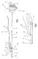
- a device shown in the figures for introducing at least one anchor piece into a cavity of a living being is indicated in its entirety by the reference numeral 10.
- the device 10 on two shaft-like elements 12, 14, at the proximal end 16, a head 18 is arranged.
- the shaft-like elements 12, 14 are movable relative to each other.
- one of the shaft-like members 12 is formed as an outer tube 20.
- the other shaft-like member 14 is formed as an inner shaft 22 received in the outer tube 20.
- a distal end 24 of the inner shaft 22 is formed as a tip 26 which facilitates targeting and insertion of the device 10 of the invention through the abdominal wall into the uterus.
- a recess 28 is formed, as shown in particular from the magnification ßerten representation of FIG. 4 is apparent.
- an anchor piece 30 can be accommodated.
- the anchor piece 30 has a strip-shaped body 32 (see also FIG. 2 ).
- the body 32 is in the form of a pipe section whose geometry corresponds to the geometry of the outer pipe 20.
- the anchor piece 30 is rounded at its two ends.
- the anchor piece 30 has two central openings 34, 36, through which a drawstring 38 is threaded.
- the anchor piece 30 has two end openings 40, 42, which are arranged on one side of the anchor piece 30. Through the end-side openings 40, 42 a Bergefaden 44 is threaded.
- the pull thread 38 which is significantly longer than the ridge thread 44, serves to fix the uterine wall to the abdominal wall.
- the shorter Bergefaden 44 against serves to remove the anchor piece 30 at the end of the examination or surgery, as will be described below.
- the inner shaft 22 has two recesses 74, 76, which are arranged at the location at which the central openings 34, 36 and the end-side openings 40, 42 of the anchor piece 30 come to rest. In these recesses 74, 76, the threads 38, 44 can be inserted.
- the device 10 has an actuating mechanism 46, via which one of the shaft-like elements 12, 14 is movable in such a way that the anchor piece 30 held by the latter is released.
- the actuating mechanism 46 has an actuating element 48 which is arranged on the head 18.
- the actuator 48 is formed as a push button 50 which is movable in the direction of the axial movement of the shaft-like elements 12, 14.
- the actuating mechanism 46 includes a spring 52 as seen in the section along a longitudinal axis 54 of FIG. 3 is apparent.
- the spring 52 acts on the inner shaft 22 in such a way that the inner shaft 22 is pressed by means of the spring 52 in the direction of the head 18.
- the inner shaft 22 is displaced distally.
- each jaw 56, 58 is formed at the distal end of the outer tube 20 and at the proximal end of the formed at the distal end of the inner shaft 22 tip 26 .
- Each jaw 56, 58 each has a mowing pocket 60, 62.
- the milled pocket 60 formed at the distal end of the outer tube 20 lies exactly opposite the muzzle pocket 62 formed at the proximal end of the tip 26.
- the opposite muzzle pockets 60, 62 avoid radially displacing the anchor piece 30 which is durable between the jaws 56, 58.
- the shape of the milled pockets corresponds to the rounding of the rounded ends of the anchor piece 30.
- the actuation of the trained as the push button 50 actuator 48 which is done in this embodiment by pressing the push button 50 and with an arrow 64 in FIG. 4 is indicated causes an axial displacement of the inner shaft 22 along the longitudinal axis 54.
- the axial displacement is indicated by an arrow 66.
- the second position is defined as a distance between the two jaws 56, 58 that is greater than the length of the anchor piece 30.
- the anchor piece 30 in the formed between the jaws 56, 58 recess 28 can be inserted.
- the insertion of the anchor piece 30 is indicated by an arrow 68.
- FIG. 6 an embodiment 80 of the device according to the invention is shown, which differs from the in FIG. 4 illustrated embodiment with respect to the number of anchor pieces that are durable between the shaft-like elements, different.
- the device 80 has two also shaft-like elements 82, 84, at the proximal end 86, a head 88 is arranged.
- One of the shaft-like elements 82 is also formed as an outer tube 90 and the other shaft-like element 84 as an axially movable inner shaft 92 received in the outer tube 90.
- a distal end 87 of the inner shaft 92 is also formed as a tip 94.
- a recess 96 is also formed.
- a jaw 93, 95 is arranged in each case.
- the device 80 also has an actuating mechanism 98, which also has an actuating element 102 designed as a pushbutton 100.
- each jaw 93, 95 has two opposite muzzle pockets 118, 120; 122, 124 on.
- the actuating mechanism 98 is the same as in the first in the FIG. 4 operated embodiment shown.
- Pressing the push button 100 causes it to move axially along a longitudinal axis 106 of the inner shaft 92 (see arrow 108).
- the shaft-like elements 82, 84 are brought into the second position P 2 .
- the two anchor pieces 110, 112 are inserted into the recess 96.
- the insertion of the two anchor pieces 110, 112 is indicated by arrows 114, 116.
- FIG. 2 shows a side view of the device 10 to which a trocar 126 is fixed by means of a mechanism 128.
- Trocars are used to introduce medical instruments from the outside into the body through an incision.
- the trocar has a trocar sleeve 130 which has a shaft 132 at the proximal end of which a housing 134 is arranged.
- the housing 134 has an outer approximately hollow cylindrical portion 136 which immediately adjoins the proximal end of the hollow shaft 132. From the outer portion 136 is radially a terminal 138 before. Via the port 138, a gas can be passed into the interior of the housing 134 and through the shaft 132.
- the drawstring 38 and the not shown here Berisfaden 44 is disposed in the interior of the shaft 132 of the trocar 126.
- the shaft-like elements together with inserted anchor piece (or pieces) are introduced directly or via a trocar through the abdominal wall 140 and the uterine wall 144 in the interior of the uterus 142. This can be done under endoscopic observation.
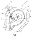
- FIG. 8 a situation is shown in which the anchor piece 30 has already been released.
- the device 10 is removed from the uterus 142, and the uterine wall 144 is attracted to the inside of the abdominal wall 140 by means of the anchor piece 30 located in the uterus 142 and the draw thread 38 threaded through the anchor piece 30, and the pull thread is taken from the outside of the abdominal wall 140 fixed with a clamp 148 ( FIG. 9 , Left).
- a prenatal examination or surgery may be performed on the fetus 146 or on the uterus 142 using medical instruments.
- the pulling thread 152 is cut off and a medical instrument 156 is inserted through the abdominal wall 140 into the uterus 142, by means of which the mountain thread 154 of the anchor piece 150 located inside the uterus 142 is gripped.
- the anchor piece 150 is removed from the uterus 142 by a shank of the medical instrument 156 ( FIG. 9 , right). This Pulling into the shaft is facilitated by the fact that the Bergefaden 154 end is attached to the anchor piece 130.
- FIG. 6 how out FIG. 6 can be seen, the inner shaft 92 on an eject mechanism 125.
- This ejection mechanism 125 allows for side ejection of the anchor pieces 110 and 112 from the inner shaft 92 if the anchor pieces 110, 112 are prevented from falling sideways by tissue or tissue fluids.
- the ejection mechanism has two laterally extendable, spring-loaded lugs 127. Such ejection mechanism can also in the execution of FIGS. 1 to 5 be provided.
Landscapes
- Health & Medical Sciences (AREA)
- Surgery (AREA)
- Life Sciences & Earth Sciences (AREA)
- Biomedical Technology (AREA)
- Nuclear Medicine, Radiotherapy & Molecular Imaging (AREA)
- Engineering & Computer Science (AREA)
- Heart & Thoracic Surgery (AREA)
- Medical Informatics (AREA)
- Molecular Biology (AREA)
- Animal Behavior & Ethology (AREA)
- General Health & Medical Sciences (AREA)
- Public Health (AREA)
- Veterinary Medicine (AREA)
- Rheumatology (AREA)
- Surgical Instruments (AREA)
Claims (20)
- Dispositif conçu pour insérer au moins une pièce d'ancrage dans une cavité d'un organisme vivant, en vue de bloquer provisoirement à demeure une paroi de ladite cavité sur une paroi corporelle, au moyen de ladite pièce d'ancrage à présence minimale, comprenant deux éléments (12, 14 ; 82, 84) du type tige, mobiles axialement l'un par rapport à l'autre et entre lesquels ladite pièce d'ancrage (30 ; 110, 112), à présence minimale, peut être retenue de manière imperdable, sachant que l'un desdits éléments (12, 14 ; 82, 84) du type tige est réalisé sous la forme d'un tube extérieur (20, 90), l'autre élément étant réalisé sous la forme d'un fût intérieur (22, 92) qui peut coulisser axialement, est logé dans ledit tube extérieur (20, 90), et dont l'extrémité distale revêt la forme d'une pointe (26, 94) ; et un mécanisme d'actionnement (46, 98) par l'intermédiaire duquel au moins un élément (14, 84) peut être mû de telle sorte que la pièce d'ancrage retenue (30 ; 110, 112) puisse être libérée, caractérisé par le fait que la pièce d'ancrage (30 ; 110, 112), à présence minimale, peut être retenue de manière imperdable par des extrémités axialement opposées ; par le fait que les éléments (12, 14 ; 82, 84) du type tige sont respectivement pourvus de mors (56, 58 ; 93, 95) entre lesquels ladite pièce d'ancrage (30 ; 110, 112), à présence minimale, peut être retenue de manière imperdable ; et par le fait qu'un mors (56, 93) est placé à l'extrémité distale du tube extérieur (20, 90), l'autre mors (58, 95) étant placé à l'extrémité proximale de la pointe (26, 94).
- Dispositif selon la revendication 1, caractérisé par le fait que les éléments (12, 14 ; 82, 84), du type tige, sont réalisés et agencés de façon à donner naissance à une zone évidée (28, 96) dans laquelle peut être retenue la pièce d'ancrage (30 ; 110, 112) à présence minimale.
- Dispositif selon la revendication 2, caractérisé par le fait que le mécanisme d'actionnement (46, 98) comporte un élément d'actionnement (48, 102) destiné à mouvoir au moins l'un (14, 84) des éléments du type tige, sachant que, dans un premier emplacement occupé par les éléments (12, 14 ; 82, 84) du type tige, la pièce d'ancrage (30 ; 110, 112) à présence minimale est retenue de manière imperdable dans la zone évidée (28, 96), et que ladite pièce d'ancrage (30 ; 110, 112) à présence minimale peut être insérée ou libérée dans un second emplacement occupé par lesdits éléments (12, 14 ; 82, 84) du type tige.
- Dispositif selon l'une des revendications 1 à 3, caractérisé par le fait que le mécanisme d'actionnement (46, 98) comporte un ressort (52) sollicitant l'élément (14, 84) du type tige, à présence minimale, de façon que les éléments (12, 14 ; 82, 84) du type tige soient amenés au premier emplacement.
- Dispositif selon la revendication 4, caractérisé par le fait que, lors de la manoeuvre, l'élément d'actionnement (48, 102) imprime un mouvement aux éléments (12, 14 ; 82, 84) du type tige, en opposition à la force du ressort (52), de façon telle qu'ils soient amenés au second emplacement ; et par le fait que lesdits éléments (12, 14 ; 82, 84) du type tige sont ramenés au premier emplacement lors de la libération dudit élément d'actionnement (48, 102).
- Dispositif selon l'une des revendications 1 à 5, caractérisé par le fait qu'une tête (18, 88) est située à une extrémité proximale (16, 86) des éléments (12, 14 ; 82, 84) du type tige.
- Dispositif selon la revendication 6, caractérisé par le fait que félément d'actionnement (48, 102) est réalisé sous la forme d'un bouton-poussoir (50, 100) placé sur la tête (18, 88).
- Dispositif selon l'une des revendications 3 à 7, caractérisé par le fait que l'élément d'actionnement (48, 102) peut être mû dans la direction du mouvement axial des éléments (12, 14 ; 82, 84) du type tige.
- Dispositif selon l'une des revendications 1 à 8, caractérisé par le fait que le fût intérieur (22, 92) est poussé en direction de la tête (18, 88), au moyen d'un ressort (52).
- Dispositif selon l'une des revendications 1 à 9, caractérisé par le fait que le fût intérieur (22, 92) est en liaison opérante avec le mécanisme d'actionnement (46, 98), de telle sorte qu'une manoeuvre de l'élément d'actionnement (48, 102) provoque un coulissement axial dudit fût intérieur (22, 92) le long d'un axe longitudinal (54, 106).
- Dispositif selon l'une des revendications 1 à 10, caractérisé par le fait que chaque mors (56, 58 ; 93, 95) présente au moins un logement fraisé (60, 62 ; 118, 120, 122, 124).
- Dispositif selon l'une des revendications 2 à 11, caractérisé par le fait que la zone évidée (28, 96) est réalisée de façon telle que deux pièces d'ancrage (110, 112), situées en vis-à-vis, puissent être retenues dans cette dernière.
- Dispositif selon l'une des revendications 1 à 12, caractérisé par le fait que chaque mors (93, 95) comprend deux logements fraisés (118, 120, 122, 124) tournés mutuellement à l'opposé.
- Dispositif selon l'une des revendications 1 à 13, caractérisé par le fait qu'un mécanisme (128) est placé sur la tête (18, 88), en vue de l'implantation d'un trocart (126).
- Dispositif selon l'une des revendications 1 à 14, caractérisé par la présence d'un mécanisme d'éjection (125), conçu pour éjecter la pièce d'ancrage (110, 112) à présence minimale.
- Dispositif selon l'une des revendications 1 à 15, équipé d'une pièce d'ancrage conçue pour être utilisée avec ce dispositif, et pourvue d'un corps (32) réalisé en forme de bande.
- Dispositif équipé d'une pièce d'ancrage, selon la revendication 16, caractérisé par le fait que le corps en forme de bande se présente comme un tronçon tubulaire et est doté d'un profil géométrique du tube extérieur (20, 90).
- Dispositif équipé d'une pièce d'ancrage, selon la revendication 16 ou 17, caractérisé par le fait que la pièce d'ancrage (30 ; 110, 112) est de réalisation arrondie aux deux extrémités.
- Dispositif équipé d'une pièce d'ancrage, selon l'une des revendications 16 à 18, caractérisé par le fait que la pièce d'ancrage (30 ; 110, 112) est munie d'au moins un orifice (34, 36) approximativement central, en vue de l'engagement d'un fil de traction (38).
- Dispositif équipé d'une pièce d'ancrage, selon l'une des revendications 16 à 19, caractérisé par le fait que la pièce d'ancrage (30 ; 110, 112) est munie d'au moins un orifice d'extrémité (40, 42), en vue de l'engagement d'un fil de sauvegarde (44).
Applications Claiming Priority (1)
| Application Number | Priority Date | Filing Date | Title |
|---|---|---|---|
| DE102006042633A DE102006042633A1 (de) | 2006-08-31 | 2006-08-31 | Vorrichtung zum Einführen zumindest eines Ankerstücks in einen Hohlraum eines Lebewesens |
Publications (3)
| Publication Number | Publication Date |
|---|---|
| EP1894529A2 EP1894529A2 (fr) | 2008-03-05 |
| EP1894529A3 EP1894529A3 (fr) | 2008-08-20 |
| EP1894529B1 true EP1894529B1 (fr) | 2013-08-21 |
Family
ID=38789455
Family Applications (1)
| Application Number | Title | Priority Date | Filing Date |
|---|---|---|---|
| EP07016790.3A Not-in-force EP1894529B1 (fr) | 2006-08-31 | 2007-08-28 | Dispositif destiné à l'introduction d'au moins un élément d'ancrage dans un espace creux d'un être vivant |
Country Status (3)
| Country | Link |
|---|---|
| US (1) | US8142449B2 (fr) |
| EP (1) | EP1894529B1 (fr) |
| DE (1) | DE102006042633A1 (fr) |
Families Citing this family (8)
| Publication number | Priority date | Publication date | Assignee | Title |
|---|---|---|---|---|
| WO2007124773A1 (fr) * | 2006-04-28 | 2007-11-08 | Covidien Ag | Kit organopexique |
| US8453913B2 (en) | 2009-02-06 | 2013-06-04 | Covidien Lp | Anvil for surgical stapler |
| FR2942391B1 (fr) * | 2009-02-25 | 2012-06-15 | Protomed | Dispositif chirurgical d'ecartement et son procede de fabrication. |
| US9737289B2 (en) * | 2010-10-29 | 2017-08-22 | Vectec S.A. | Single use, disposable, tissue suspender device |
| US9700291B2 (en) * | 2014-06-03 | 2017-07-11 | Biomet Sports Medicine, Llc | Capsule retractor |
| WO2017095681A1 (fr) * | 2015-12-04 | 2017-06-08 | First Ray, LLC | Dispositifs d'ancrage de tissu |
| CN109938789B (zh) * | 2019-02-01 | 2024-03-26 | 汕头大学 | 一种微创腹腔手术器材的推钉装置 |
| US20210307780A1 (en) * | 2020-04-01 | 2021-10-07 | Ruben Quintero | Obturator and cannula for uterine and fetal surgeries |
Family Cites Families (12)
| Publication number | Priority date | Publication date | Assignee | Title |
|---|---|---|---|---|
| US4235238A (en) * | 1978-05-11 | 1980-11-25 | Olympus Optical Co., Ltd. | Apparatus for suturing coeliac tissues |
| US4741330A (en) * | 1983-05-19 | 1988-05-03 | Hayhurst John O | Method and apparatus for anchoring and manipulating cartilage |
| US5021059A (en) * | 1990-05-07 | 1991-06-04 | Kensey Nash Corporation | Plug device with pulley for sealing punctures in tissue and methods of use |
| US5085661A (en) * | 1990-10-29 | 1992-02-04 | Gerald Moss | Surgical fastener implantation device |
| US5282827A (en) * | 1991-11-08 | 1994-02-01 | Kensey Nash Corporation | Hemostatic puncture closure system and method of use |
| US5676689A (en) * | 1991-11-08 | 1997-10-14 | Kensey Nash Corporation | Hemostatic puncture closure system including vessel location device and method of use |
| CA2124651C (fr) * | 1993-08-20 | 2004-09-28 | David T. Green | Appareil et methode pour mettre en place et ajuster un dispositif d'ancrage de structures internes |
| US5626614A (en) * | 1995-12-22 | 1997-05-06 | Applied Medical Resources Corporation | T-anchor suturing device and method for using same |
| US5718717A (en) * | 1996-08-19 | 1998-02-17 | Bonutti; Peter M. | Suture anchor |
| US6110183A (en) * | 1998-12-22 | 2000-08-29 | Cook Incorporated | Suture anchor device |
| US6972027B2 (en) * | 2002-06-26 | 2005-12-06 | Stryker Endoscopy | Soft tissue repair system |
| WO2005110280A2 (fr) * | 2004-05-07 | 2005-11-24 | Valentx, Inc. | Dispositifs et méthodes pour arrimer un implant endolumenal gastro-intestinal |
-
2006
- 2006-08-31 DE DE102006042633A patent/DE102006042633A1/de not_active Withdrawn
-
2007
- 2007-08-28 EP EP07016790.3A patent/EP1894529B1/fr not_active Not-in-force
- 2007-08-31 US US11/848,275 patent/US8142449B2/en not_active Expired - Fee Related
Also Published As
| Publication number | Publication date |
|---|---|
| EP1894529A2 (fr) | 2008-03-05 |
| EP1894529A3 (fr) | 2008-08-20 |
| DE102006042633A1 (de) | 2008-03-13 |
| US20080071297A1 (en) | 2008-03-20 |
| US8142449B2 (en) | 2012-03-27 |
Similar Documents
| Publication | Publication Date | Title |
|---|---|---|
| EP2060236B1 (fr) | Instrument médical destiné à la manipulation de l'utérus | |
| EP1894529B1 (fr) | Dispositif destiné à l'introduction d'au moins un élément d'ancrage dans un espace creux d'un être vivant | |
| DE69430727T2 (de) | Greifereinrichtung für nahtmaterial | |
| DE69622969T2 (de) | Wundverschlussvorrichtung | |
| DE19704580C2 (de) | Chirurgischer Fadenschneider | |
| DE69735501T2 (de) | Systeme und instrumente zur minimal invasiven chirurgie | |
| EP2049037B1 (fr) | Dispositif pour introduire et positionner des instruments chirurgicaux | |
| EP2185061B1 (fr) | Fourreau de trocart, trocart, obturateur et rectoscope pour chirurgie endoscopique transluminale par les voies naturelles | |
| EP1897505B1 (fr) | Instrument médical | |
| DE112012001952B4 (de) | Einwegkanüle für Endoskopie | |
| EP2015816B1 (fr) | Dispositif de cathétérisme pour interventions percutanées | |
| EP2957233B1 (fr) | Aiguille à biopsie articulée destinée au prélèvement d'échantillons de tissus | |
| DE2436666A1 (de) | Applikatorvorrichtung zum anlegen eines verschlussrings an anatomischen rohrfoermigen strukturen | |
| EP2497433B1 (fr) | Système de trocart multiple | |
| DE29909688U1 (de) | Instrument zur chirurgischen Ligation | |
| DE3926320C2 (de) | Anzeigevorrichtung zur Verwendung mit einem Endoskop | |
| EP1744681A2 (fr) | Rivet aveugle pour l'adaptation de tissu biologique et dispositif pour mettre en place ledit rivet aveugle, notamment a travers le canal instrumental d'un endoscope | |
| EP1839604A1 (fr) | Dispositif destiné à l'exécution de recherches et opérations chirurgicales de l'utérus | |
| EP2313010B1 (fr) | Dispositif chirurgical | |
| DE112014004005T5 (de) | Endoskopisches chirurgisches Gerät, Überrohr und Aussenrohr | |
| DE69113432T2 (de) | Einsatz für Trokar mit Schutzhülse. | |
| DE9109909U1 (de) | Operationsinstrument | |
| DE102016122543A1 (de) | Chirurgisches Stabelement und Instrumentenset für minimalinvasive Ausführung einer Einzelnaht | |
| DE19955614C1 (de) | Falloposkop für die Untersuchung von Eierstöcken und Eileitern | |
| DE2922511A1 (de) | Abdominaler injektor |
Legal Events
| Date | Code | Title | Description |
|---|---|---|---|
| PUAI | Public reference made under article 153(3) epc to a published international application that has entered the european phase |
Free format text: ORIGINAL CODE: 0009012 |
|
| AK | Designated contracting states |
Kind code of ref document: A2 Designated state(s): AT BE BG CH CY CZ DE DK EE ES FI FR GB GR HU IE IS IT LI LT LU LV MC MT NL PL PT RO SE SI SK TR |
|
| AX | Request for extension of the european patent |
Extension state: AL BA HR MK YU |
|
| PUAL | Search report despatched |
Free format text: ORIGINAL CODE: 0009013 |
|
| AK | Designated contracting states |
Kind code of ref document: A3 Designated state(s): AT BE BG CH CY CZ DE DK EE ES FI FR GB GR HU IE IS IT LI LT LU LV MC MT NL PL PT RO SE SI SK TR |
|
| AX | Request for extension of the european patent |
Extension state: AL BA HR MK RS |
|
| 17P | Request for examination filed |
Effective date: 20090211 |
|
| 17Q | First examination report despatched |
Effective date: 20090309 |
|
| AKX | Designation fees paid |
Designated state(s): AT BE BG CH CY CZ DE DK EE ES FI FR GB GR HU IE IS IT LI LT LU LV MC MT NL PL PT RO SE SI SK TR |
|
| GRAP | Despatch of communication of intention to grant a patent |
Free format text: ORIGINAL CODE: EPIDOSNIGR1 |
|
| GRAS | Grant fee paid |
Free format text: ORIGINAL CODE: EPIDOSNIGR3 |
|
| GRAA | (expected) grant |
Free format text: ORIGINAL CODE: 0009210 |
|
| AK | Designated contracting states |
Kind code of ref document: B1 Designated state(s): AT BE BG CH CY CZ DE DK EE ES FI FR GB GR HU IE IS IT LI LT LU LV MC MT NL PL PT RO SE SI SK TR |
|
| REG | Reference to a national code |
Ref country code: GB Ref legal event code: FG4D Free format text: NOT ENGLISH |
|
| REG | Reference to a national code |
Ref country code: CH Ref legal event code: EP |
|
| REG | Reference to a national code |
Ref country code: AT Ref legal event code: REF Ref document number: 627564 Country of ref document: AT Kind code of ref document: T Effective date: 20130915 |
|
| REG | Reference to a national code |
Ref country code: IE Ref legal event code: FG4D Free format text: LANGUAGE OF EP DOCUMENT: GERMAN |
|
| REG | Reference to a national code |
Ref country code: DE Ref legal event code: R096 Ref document number: 502007012177 Country of ref document: DE Effective date: 20131010 |
|
| REG | Reference to a national code |
Ref country code: NL Ref legal event code: VDEP Effective date: 20130821 |
|
| REG | Reference to a national code |
Ref country code: LT Ref legal event code: MG4D |
|
| PG25 | Lapsed in a contracting state [announced via postgrant information from national office to epo] |
Ref country code: CY Free format text: LAPSE BECAUSE OF FAILURE TO SUBMIT A TRANSLATION OF THE DESCRIPTION OR TO PAY THE FEE WITHIN THE PRESCRIBED TIME-LIMIT Effective date: 20130703 Ref country code: IS Free format text: LAPSE BECAUSE OF FAILURE TO SUBMIT A TRANSLATION OF THE DESCRIPTION OR TO PAY THE FEE WITHIN THE PRESCRIBED TIME-LIMIT Effective date: 20131221 Ref country code: SE Free format text: LAPSE BECAUSE OF FAILURE TO SUBMIT A TRANSLATION OF THE DESCRIPTION OR TO PAY THE FEE WITHIN THE PRESCRIBED TIME-LIMIT Effective date: 20130821 Ref country code: PT Free format text: LAPSE BECAUSE OF FAILURE TO SUBMIT A TRANSLATION OF THE DESCRIPTION OR TO PAY THE FEE WITHIN THE PRESCRIBED TIME-LIMIT Effective date: 20131223 Ref country code: LT Free format text: LAPSE BECAUSE OF FAILURE TO SUBMIT A TRANSLATION OF THE DESCRIPTION OR TO PAY THE FEE WITHIN THE PRESCRIBED TIME-LIMIT Effective date: 20130821 |
|
| BERE | Be: lapsed |
Owner name: KARL STORZ G.M.B.H. & CO. KG Effective date: 20130831 |
|
| PG25 | Lapsed in a contracting state [announced via postgrant information from national office to epo] |
Ref country code: LV Free format text: LAPSE BECAUSE OF FAILURE TO SUBMIT A TRANSLATION OF THE DESCRIPTION OR TO PAY THE FEE WITHIN THE PRESCRIBED TIME-LIMIT Effective date: 20130821 Ref country code: GR Free format text: LAPSE BECAUSE OF FAILURE TO SUBMIT A TRANSLATION OF THE DESCRIPTION OR TO PAY THE FEE WITHIN THE PRESCRIBED TIME-LIMIT Effective date: 20131122 Ref country code: SI Free format text: LAPSE BECAUSE OF FAILURE TO SUBMIT A TRANSLATION OF THE DESCRIPTION OR TO PAY THE FEE WITHIN THE PRESCRIBED TIME-LIMIT Effective date: 20130821 Ref country code: FI Free format text: LAPSE BECAUSE OF FAILURE TO SUBMIT A TRANSLATION OF THE DESCRIPTION OR TO PAY THE FEE WITHIN THE PRESCRIBED TIME-LIMIT Effective date: 20130821 Ref country code: ES Free format text: LAPSE BECAUSE OF FAILURE TO SUBMIT A TRANSLATION OF THE DESCRIPTION OR TO PAY THE FEE WITHIN THE PRESCRIBED TIME-LIMIT Effective date: 20130821 Ref country code: PL Free format text: LAPSE BECAUSE OF FAILURE TO SUBMIT A TRANSLATION OF THE DESCRIPTION OR TO PAY THE FEE WITHIN THE PRESCRIBED TIME-LIMIT Effective date: 20130821 |
|
| PG25 | Lapsed in a contracting state [announced via postgrant information from national office to epo] |
Ref country code: CY Free format text: LAPSE BECAUSE OF FAILURE TO SUBMIT A TRANSLATION OF THE DESCRIPTION OR TO PAY THE FEE WITHIN THE PRESCRIBED TIME-LIMIT Effective date: 20130821 |
|
| REG | Reference to a national code |
Ref country code: CH Ref legal event code: PL |
|
| PG25 | Lapsed in a contracting state [announced via postgrant information from national office to epo] |
Ref country code: RO Free format text: LAPSE BECAUSE OF FAILURE TO SUBMIT A TRANSLATION OF THE DESCRIPTION OR TO PAY THE FEE WITHIN THE PRESCRIBED TIME-LIMIT Effective date: 20130821 Ref country code: DK Free format text: LAPSE BECAUSE OF FAILURE TO SUBMIT A TRANSLATION OF THE DESCRIPTION OR TO PAY THE FEE WITHIN THE PRESCRIBED TIME-LIMIT Effective date: 20130821 Ref country code: CH Free format text: LAPSE BECAUSE OF NON-PAYMENT OF DUE FEES Effective date: 20130831 Ref country code: NL Free format text: LAPSE BECAUSE OF FAILURE TO SUBMIT A TRANSLATION OF THE DESCRIPTION OR TO PAY THE FEE WITHIN THE PRESCRIBED TIME-LIMIT Effective date: 20130821 Ref country code: LI Free format text: LAPSE BECAUSE OF NON-PAYMENT OF DUE FEES Effective date: 20130831 Ref country code: CZ Free format text: LAPSE BECAUSE OF FAILURE TO SUBMIT A TRANSLATION OF THE DESCRIPTION OR TO PAY THE FEE WITHIN THE PRESCRIBED TIME-LIMIT Effective date: 20130821 Ref country code: SK Free format text: LAPSE BECAUSE OF FAILURE TO SUBMIT A TRANSLATION OF THE DESCRIPTION OR TO PAY THE FEE WITHIN THE PRESCRIBED TIME-LIMIT Effective date: 20130821 Ref country code: EE Free format text: LAPSE BECAUSE OF FAILURE TO SUBMIT A TRANSLATION OF THE DESCRIPTION OR TO PAY THE FEE WITHIN THE PRESCRIBED TIME-LIMIT Effective date: 20130821 |
|
| REG | Reference to a national code |
Ref country code: IE Ref legal event code: MM4A |
|
| PG25 | Lapsed in a contracting state [announced via postgrant information from national office to epo] |
Ref country code: MC Free format text: LAPSE BECAUSE OF FAILURE TO SUBMIT A TRANSLATION OF THE DESCRIPTION OR TO PAY THE FEE WITHIN THE PRESCRIBED TIME-LIMIT Effective date: 20130821 Ref country code: BE Free format text: LAPSE BECAUSE OF NON-PAYMENT OF DUE FEES Effective date: 20130831 |
|
| PLBE | No opposition filed within time limit |
Free format text: ORIGINAL CODE: 0009261 |
|
| STAA | Information on the status of an ep patent application or granted ep patent |
Free format text: STATUS: NO OPPOSITION FILED WITHIN TIME LIMIT |
|
| 26N | No opposition filed |
Effective date: 20140522 |
|
| PG25 | Lapsed in a contracting state [announced via postgrant information from national office to epo] |
Ref country code: IE Free format text: LAPSE BECAUSE OF NON-PAYMENT OF DUE FEES Effective date: 20130828 |
|
| REG | Reference to a national code |
Ref country code: DE Ref legal event code: R097 Ref document number: 502007012177 Country of ref document: DE Effective date: 20140522 |
|
| REG | Reference to a national code |
Ref country code: AT Ref legal event code: MM01 Ref document number: 627564 Country of ref document: AT Kind code of ref document: T Effective date: 20130828 |
|
| PG25 | Lapsed in a contracting state [announced via postgrant information from national office to epo] |
Ref country code: AT Free format text: LAPSE BECAUSE OF NON-PAYMENT OF DUE FEES Effective date: 20130828 |
|
| PG25 | Lapsed in a contracting state [announced via postgrant information from national office to epo] |
Ref country code: TR Free format text: LAPSE BECAUSE OF FAILURE TO SUBMIT A TRANSLATION OF THE DESCRIPTION OR TO PAY THE FEE WITHIN THE PRESCRIBED TIME-LIMIT Effective date: 20130821 Ref country code: MT Free format text: LAPSE BECAUSE OF FAILURE TO SUBMIT A TRANSLATION OF THE DESCRIPTION OR TO PAY THE FEE WITHIN THE PRESCRIBED TIME-LIMIT Effective date: 20130821 |
|
| PG25 | Lapsed in a contracting state [announced via postgrant information from national office to epo] |
Ref country code: HU Free format text: LAPSE BECAUSE OF FAILURE TO SUBMIT A TRANSLATION OF THE DESCRIPTION OR TO PAY THE FEE WITHIN THE PRESCRIBED TIME-LIMIT; INVALID AB INITIO Effective date: 20070828 Ref country code: BG Free format text: LAPSE BECAUSE OF FAILURE TO SUBMIT A TRANSLATION OF THE DESCRIPTION OR TO PAY THE FEE WITHIN THE PRESCRIBED TIME-LIMIT Effective date: 20130821 Ref country code: LU Free format text: LAPSE BECAUSE OF NON-PAYMENT OF DUE FEES Effective date: 20130828 |
|
| REG | Reference to a national code |
Ref country code: FR Ref legal event code: PLFP Year of fee payment: 10 |
|
| REG | Reference to a national code |
Ref country code: FR Ref legal event code: PLFP Year of fee payment: 11 |
|
| PGFP | Annual fee paid to national office [announced via postgrant information from national office to epo] |
Ref country code: ES Payment date: 20170704 Year of fee payment: 11 Ref country code: GB Payment date: 20170719 Year of fee payment: 11 Ref country code: FR Payment date: 20170720 Year of fee payment: 11 |
|
| REG | Reference to a national code |
Ref country code: DE Ref legal event code: R081 Ref document number: 502007012177 Country of ref document: DE Owner name: KARL STORZ SE & CO. KG INTELLECTUAL PROPERTY, DE Free format text: FORMER OWNER: KARL STORZ GMBH & CO. KG, 78532 TUTTLINGEN, DE Ref country code: DE Ref legal event code: R082 Ref document number: 502007012177 Country of ref document: DE Representative=s name: WITTE, WELLER & PARTNER PATENTANWAELTE MBB, DE Ref country code: DE Ref legal event code: R081 Ref document number: 502007012177 Country of ref document: DE Owner name: KARL STORZ SE & CO. KG, DE Free format text: FORMER OWNER: KARL STORZ GMBH & CO. KG, 78532 TUTTLINGEN, DE |
|
| GBPC | Gb: european patent ceased through non-payment of renewal fee |
Effective date: 20180828 |
|
| PG25 | Lapsed in a contracting state [announced via postgrant information from national office to epo] |
Ref country code: IT Free format text: LAPSE BECAUSE OF NON-PAYMENT OF DUE FEES Effective date: 20180828 |
|
| PG25 | Lapsed in a contracting state [announced via postgrant information from national office to epo] |
Ref country code: FR Free format text: LAPSE BECAUSE OF NON-PAYMENT OF DUE FEES Effective date: 20180831 |
|
| PG25 | Lapsed in a contracting state [announced via postgrant information from national office to epo] |
Ref country code: GB Free format text: LAPSE BECAUSE OF NON-PAYMENT OF DUE FEES Effective date: 20180828 |
|
| PGFP | Annual fee paid to national office [announced via postgrant information from national office to epo] |
Ref country code: DE Payment date: 20220616 Year of fee payment: 16 |
|
| P01 | Opt-out of the competence of the unified patent court (upc) registered |
Effective date: 20230527 |
|
| REG | Reference to a national code |
Ref country code: DE Ref legal event code: R119 Ref document number: 502007012177 Country of ref document: DE |
|
| PG25 | Lapsed in a contracting state [announced via postgrant information from national office to epo] |
Ref country code: DE Free format text: LAPSE BECAUSE OF NON-PAYMENT OF DUE FEES Effective date: 20240301 |