EP1893877B1 - Joint d'arbre - Google Patents
Joint d'arbre Download PDFInfo
- Publication number
- EP1893877B1 EP1893877B1 EP07722423A EP07722423A EP1893877B1 EP 1893877 B1 EP1893877 B1 EP 1893877B1 EP 07722423 A EP07722423 A EP 07722423A EP 07722423 A EP07722423 A EP 07722423A EP 1893877 B1 EP1893877 B1 EP 1893877B1
- Authority
- EP
- European Patent Office
- Prior art keywords
- sealing element
- ring
- roller
- shaft
- seal
- Prior art date
- Legal status (The legal status is an assumption and is not a legal conclusion. Google has not performed a legal analysis and makes no representation as to the accuracy of the status listed.)
- Active
Links
Images
Classifications
-
- F—MECHANICAL ENGINEERING; LIGHTING; HEATING; WEAPONS; BLASTING
- F16—ENGINEERING ELEMENTS AND UNITS; GENERAL MEASURES FOR PRODUCING AND MAINTAINING EFFECTIVE FUNCTIONING OF MACHINES OR INSTALLATIONS; THERMAL INSULATION IN GENERAL
- F16J—PISTONS; CYLINDERS; SEALINGS
- F16J15/00—Sealings
- F16J15/16—Sealings between relatively-moving surfaces
- F16J15/32—Sealings between relatively-moving surfaces with elastic sealings, e.g. O-rings
- F16J15/3268—Mounting of sealing rings
-
- F—MECHANICAL ENGINEERING; LIGHTING; HEATING; WEAPONS; BLASTING
- F16—ENGINEERING ELEMENTS AND UNITS; GENERAL MEASURES FOR PRODUCING AND MAINTAINING EFFECTIVE FUNCTIONING OF MACHINES OR INSTALLATIONS; THERMAL INSULATION IN GENERAL
- F16C—SHAFTS; FLEXIBLE SHAFTS; ELEMENTS OR CRANKSHAFT MECHANISMS; ROTARY BODIES OTHER THAN GEARING ELEMENTS; BEARINGS
- F16C13/00—Rolls, drums, discs, or the like; Bearings or mountings therefor
- F16C13/02—Bearings
- F16C13/022—Bearings supporting a hollow roll mantle rotating with respect to a yoke or axle
-
- F—MECHANICAL ENGINEERING; LIGHTING; HEATING; WEAPONS; BLASTING
- F16—ENGINEERING ELEMENTS AND UNITS; GENERAL MEASURES FOR PRODUCING AND MAINTAINING EFFECTIVE FUNCTIONING OF MACHINES OR INSTALLATIONS; THERMAL INSULATION IN GENERAL
- F16C—SHAFTS; FLEXIBLE SHAFTS; ELEMENTS OR CRANKSHAFT MECHANISMS; ROTARY BODIES OTHER THAN GEARING ELEMENTS; BEARINGS
- F16C33/00—Parts of bearings; Special methods for making bearings or parts thereof
- F16C33/72—Sealings
- F16C33/76—Sealings of ball or roller bearings
- F16C33/78—Sealings of ball or roller bearings with a diaphragm, disc, or ring, with or without resilient members
-
- F—MECHANICAL ENGINEERING; LIGHTING; HEATING; WEAPONS; BLASTING
- F16—ENGINEERING ELEMENTS AND UNITS; GENERAL MEASURES FOR PRODUCING AND MAINTAINING EFFECTIVE FUNCTIONING OF MACHINES OR INSTALLATIONS; THERMAL INSULATION IN GENERAL
- F16C—SHAFTS; FLEXIBLE SHAFTS; ELEMENTS OR CRANKSHAFT MECHANISMS; ROTARY BODIES OTHER THAN GEARING ELEMENTS; BEARINGS
- F16C33/00—Parts of bearings; Special methods for making bearings or parts thereof
- F16C33/72—Sealings
- F16C33/76—Sealings of ball or roller bearings
- F16C33/80—Labyrinth sealings
-
- F—MECHANICAL ENGINEERING; LIGHTING; HEATING; WEAPONS; BLASTING
- F16—ENGINEERING ELEMENTS AND UNITS; GENERAL MEASURES FOR PRODUCING AND MAINTAINING EFFECTIVE FUNCTIONING OF MACHINES OR INSTALLATIONS; THERMAL INSULATION IN GENERAL
- F16J—PISTONS; CYLINDERS; SEALINGS
- F16J15/00—Sealings
- F16J15/16—Sealings between relatively-moving surfaces
- F16J15/34—Sealings between relatively-moving surfaces with slip-ring pressed against a more or less radial face on one member
- F16J15/3436—Pressing means
- F16J15/3456—Pressing means without external means for pressing the ring against the face, e.g. slip-ring with a resilient lip
-
- F—MECHANICAL ENGINEERING; LIGHTING; HEATING; WEAPONS; BLASTING
- F16—ENGINEERING ELEMENTS AND UNITS; GENERAL MEASURES FOR PRODUCING AND MAINTAINING EFFECTIVE FUNCTIONING OF MACHINES OR INSTALLATIONS; THERMAL INSULATION IN GENERAL
- F16J—PISTONS; CYLINDERS; SEALINGS
- F16J15/00—Sealings
- F16J15/44—Free-space packings
- F16J15/447—Labyrinth packings
- F16J15/4472—Labyrinth packings with axial path
- F16J15/4474—Pre-assembled packings
-
- F—MECHANICAL ENGINEERING; LIGHTING; HEATING; WEAPONS; BLASTING
- F16—ENGINEERING ELEMENTS AND UNITS; GENERAL MEASURES FOR PRODUCING AND MAINTAINING EFFECTIVE FUNCTIONING OF MACHINES OR INSTALLATIONS; THERMAL INSULATION IN GENERAL
- F16C—SHAFTS; FLEXIBLE SHAFTS; ELEMENTS OR CRANKSHAFT MECHANISMS; ROTARY BODIES OTHER THAN GEARING ELEMENTS; BEARINGS
- F16C2326/00—Articles relating to transporting
- F16C2326/58—Conveyor systems, e.g. rollers or bearings therefor
Definitions
- the present invention relates to a shaft seal having an axle seal disposed on an inner seal member having at least one ring, and disposed on a roller body outer seal member having at least one ring which is aligned substantially parallel to the at least one ring of the inner seal member ,
- the present invention further relates to a roller for conveyors, in particular belt or belt conveyor, with a hollow cylindrical roller body and a mounted in at least two bearings axle shaft, wherein a shaft seal is arranged on the bearings in each case.
- Such shaft seals when the inner and outer seal members do not contact each other, are commonly referred to as a labyrinth seal.
- the sealing effect between a rotating shaft in a housing is generated by suitable arrangement of the rings on the shaft, which run in corresponding grooves on the fixed housing.
- the sealing path is extended by a multiple. The extension of the sealing path causes a pressure reduction due to the occurring friction of the medium located in the sealing path, which must be so large that at the end of the sealing path there is no or almost no pressure difference to the pressure outside of the shaft seal.
- the sealing path has alternately successively a plurality of chambers, which are connected to each other via a labyrinth gap, forming the throttle points.
- the pressure energy partially converted into kinetic energy in the labyrinth gaps is lowered in the following chambers, since it is partly consumed by vortex formation, partly as heat, and thus the pressure energy is lost.
- a sequence of several chambers and labyrinth gaps connected in series thus reduces a high pressure level in front of the shaft seal to a low pressure level behind it.
- the labyrinth or sealing gap usually has its smallest width between the end faces of the rings and the grooves. But the sealing effect can, as in the DE 20163734 , in the mentioned document, a shaft seal is disclosed in which the side surfaces of the rings and grooves in the installed state in contact with each other and at the start of operation so einschleifen each other that a low Gap is achieved.
- a ring-shaped circumferential to a ring of the other sealing element facing projection is provided on a ring of one of the two sealing elements. It is further provided according to the invention that the projection in an assembly of the shaft seal in contact with the ring of the other sealing element and abrades after the start of a rotational movement of the axle shaft and / or the roller body, to a narrow annular gap between the projection and the ring of the other sealing element is trained.
- the shaft seal is initially a contact seal having a desired wear point.
- the projection is partially ground between the projection and the opposite ring thus a narrow annular gap is formed, which is non-contact in the entire circumference of the shaft seal.
- curl time is a non-contact labyrinth seal educated.
- the projection is ground down only to the extent required for non-contact operation, since the abrading is terminated automatically then.
- a comparatively narrow annular gap is possible with conventional shaft seals only with a high-precision manufacturing and assembly accuracy, which can increase the manufacturing cost of such a shaft seal considerably.
- the roller according to the invention for a conveyor has a shaft seal according to the invention. Once the shaft seal runs without contact, a uniform rotation of the conveyor roller is ensured. This leads to a significantly reduced wear of the roller shell, since due to the uniform speed lifting the belt (in a belt conveyor) and subsequent falling is avoided. Further, especially in conveyor systems with a variety of conveyor rollers to form a conveyor belt up to several kilometers long, it is important that the production of the rollers including the seals is inexpensive and the rollers have a long service life.
- the projection preferably tapers.
- the tapered projection is a compromise between the requirement of low friction and sufficient stability and the cut forms a blunt tip on the projection.
- An advantageous embodiment of the shaft seal according to the invention provides that the axle shaft is provided as a stator and the roller body as a rotor.
- a sealing path is provided, in which is assigned by the two opposing boundary walls, one the inner seal member and the other the outer seal member.
- the rings of the inner sealing element and the rings of the outer sealing element are arranged alternately in the axial direction of the axle shaft.
- the inner sealing element and / or the outer sealing element are advantageously provided in one piece.
- the shaft seal according to the invention also works reliably under a load, it can preferably be used for a roller of a conveyor, in particular a belt or belt conveyor.
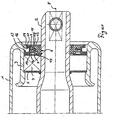
- the single FIGURE shows a longitudinal section through an embodiment of the shaft seal according to the invention.
- the representation of the figure is a partial longitudinal section in the axial direction of a conveyor roller with a substantially hollow cylindrical roller body 1 and an axle shaft 2 which is mounted on the roller body 1.
- the end of the reel body 1 is deformed inwardly to form a bearing seat 3 for a rolling bearing 4.
- To the enclosed by the roller body 1 cavity of the bearing area with the rolling bearing 4 with an annular bearing cap 5 is completed.
- the pointing in the opposite direction or the environment side of the storage area is completed by the shaft seal according to the invention.
- the shaft seal know an arranged on the axle 2 inner sealing element 6 on.
- the inner seal member 6 is composed of a first inner hollow cylinder and a second inner hollow cylinder which abuts against the outside of the first hollow cylinder.
- a first inner ring 7 is arranged, so that on both sides of the central axis 8, a substantially L-shaped longitudinal section or profile is formed.
- a second inner ring 9 is arranged such that between the first inner ring 7 and the second inner ring 9, a groove-shaped gap 10 is formed.
- a third inner ring 11 which has a smaller thickness than the second ring 9, is arranged as an extension thereof.
- the three inner rings 7, 9, 11 each have with their free end radially outward.
- a seal cover 12th At the side facing the environment of the inner seal member 6 is a seal cover 12th
- the first hollow cylinder is formed integrally with the first inner ring 7. Further, the second hollow cylinder is integrally formed together with the second and third inner rings 9, 11. It is clear that the entire inner sealing element 6 may be formed in one piece.
- the material for the inner seal member 6 may be a glass fiber reinforced polyamide, for example, PA66 GF30.
- An outer sealing member 13 is disposed on the reel body 1 and, in the illustrated example of a conveying roller, together with the reel body 1, performs a rotational movement relative to the axle shaft 2 and the inner sealing member 6.
- the outer sealing member 13 is composed of an annular member having a substantially Y-shaped profile in longitudinal section and a first outer ring 14.
- the first outer ring 14 is disposed adjacent to an arm of the Y and has with its free end radially inward.
- a second outer ring 15 is formed by the leg of the Y. Also, the second outer ring 15 has with its free end radially inward, i. to the central axis 8.
- the outwardly facing arm of the Y forms a third outer ring 16 which, in contrast to the first two inner rings 14 and 15 with its free end facing radially outward.
- the outer sealing element 13 is made of a relatively soft or abradable material, for example POM or polyacetate, compared to the material of the inner sealing element 6.
- the labyrinth gap of the shaft seal is preferably filled with a lubricant or sealant, for example a grease.
- a lubricant or sealant for example a grease.
- the roller body 1 eliminates the fat acting outward centrifugal force.
- The preferably relatively viscous fat settles and "flows" slowly in the shaft seal due to gravity down. That in the lower portion of the shaft seal, the grease seals the labyrinth gap in the space around the free end of the inner ring 7. In the upper part of the shaft seal, the grease fills the space around the free end of the second outer ring 15 and seals the labyrinth gap there. In this way, protection against ingress of dirt and moisture is both in operation and at standstill of the roller body 1 allows.
Landscapes
- Engineering & Computer Science (AREA)
- General Engineering & Computer Science (AREA)
- Mechanical Engineering (AREA)
- Sealing Using Fluids, Sealing Without Contact, And Removal Of Oil (AREA)
- Sealing Devices (AREA)
- Rollers For Roller Conveyors For Transfer (AREA)
- Sealing With Elastic Sealing Lips (AREA)
Claims (8)
- Joint d'arbre destiné à servir pour un rouleau d'un convoyeur, en particulier un convoyeur à bande ou à courroie, comprenant un élément de joint intérieur (6) qui est agencé sur un arbre d'essieu (2) et présente au moins un anneau (7, 9, 11), et un élément de joint extérieur qui est agencé sur un corps de rouleau (1) et présente au moins un anneau (14, 15, 16) orienté sensiblement parallèlement à l'au moins un anneau (7, 9, 11) de l'élément de joint intérieur (6), caractérisé en ce qu'il est prévu sur l'un des anneaux (14, 15, 16) de l'un des deux éléments de joint (13), une saillie (17, 18, 19) qui s'étend en anneau en pointant vers un anneau (7, 9, 11) de l'autre élément de joint (6), et qui est en contact avec l'anneau (7, 9, 11) de l'autre élément de joint (6) lors d'un assemblage du joint d'arbre, et après le début d'un mouvement de rotation de l'arbre d'essieu (2) et/ou du corps de rouleau (1) la saillie s'use jusqu'à ce qu'il se forme une étroite fente annulaire entre la saillie (17, 18, 19) et l'anneau (7, 9, 11) de l'autre élément de joint (6).
- Rouleau pour un convoyeur, en particulier un convoyeur à bande ou à courroie, comprenant un corps de rouleau (1) en cylindre creux et un arbre d'essieu (2) monté dans au moins deux paliers (4), caractérisé en ce qu'un joint d'arbre respectif selon la revendication 1 est agencé à chaque palier (4).
- Rouleau selon la revendication 2, caractérisé en ce que la saillie (17, 18, 19) va en se rétrécissant.
- Rouleau selon la revendication 2 ou 3, caractérisé en ce que l'arbre d'essieu (2) est prévu en tant que stator et le corps de rouleau (1) en tant que rotor.
- Rouleau selon l'une ou plusieurs des revendications 2 à 4, caractérisé par trajet d'étanchéité, dans lequel parmi deux parois de délimitation se faisant face chacune, l'une est associée à l'élément de joint intérieur (6) et l'autre à l'élément de joint extérieur (13).
- Rouleau selon l'une ou plusieurs des revendications 2 à 5, caractérisé en ce que les anneaux (7, 9, 11) de l'élément de joint intérieur (6) et les anneaux (14, 15, 16) de l'élément de joint extérieur (13) sont agencés en alternance dans la direction axiale de l'arbre d'essieu (2).
- Rouleau selon l'une ou plusieurs des revendications 2 à 6, caractérisé en ce que pour plusieurs saillies (17, 18, 19) prévues, celles-ci ne sont associées qu'à l'un des deux éléments de joint (6, 13).
- Rouleau selon l'une ou plusieurs des revendications 2 à 7, caractérisé en ce que l'élément de joint intérieur (6) et/ou l'élément de joint extérieur (13) sont prévus chacun d'un seul tenant.
Priority Applications (1)
| Application Number | Priority Date | Filing Date | Title |
|---|---|---|---|
| PL07722423T PL1893877T3 (pl) | 2006-05-22 | 2007-05-11 | Uszczelnienie wałka |
Applications Claiming Priority (2)
| Application Number | Priority Date | Filing Date | Title |
|---|---|---|---|
| DE102006024154A DE102006024154B3 (de) | 2006-05-22 | 2006-05-22 | Wellendichtung |
| PCT/DE2007/000875 WO2007134576A1 (fr) | 2006-05-22 | 2007-05-11 | Joint d'arbre |
Publications (2)
| Publication Number | Publication Date |
|---|---|
| EP1893877A1 EP1893877A1 (fr) | 2008-03-05 |
| EP1893877B1 true EP1893877B1 (fr) | 2011-07-06 |
Family
ID=38190270
Family Applications (1)
| Application Number | Title | Priority Date | Filing Date |
|---|---|---|---|
| EP07722423A Active EP1893877B1 (fr) | 2006-05-22 | 2007-05-11 | Joint d'arbre |
Country Status (12)
| Country | Link |
|---|---|
| EP (1) | EP1893877B1 (fr) |
| AT (1) | ATE515643T1 (fr) |
| BR (1) | BRPI0706298A2 (fr) |
| CA (1) | CA2640477C (fr) |
| DE (1) | DE102006024154B3 (fr) |
| EA (1) | EA016414B1 (fr) |
| ES (1) | ES2369192T3 (fr) |
| PL (1) | PL1893877T3 (fr) |
| RS (1) | RS52005B (fr) |
| UA (1) | UA92799C2 (fr) |
| WO (1) | WO2007134576A1 (fr) |
| ZA (1) | ZA200806834B (fr) |
Families Citing this family (7)
| Publication number | Priority date | Publication date | Assignee | Title |
|---|---|---|---|---|
| US8844935B2 (en) * | 2011-04-13 | 2014-09-30 | Gamesa Innovation & Technology, S.L. | Seal arrangement |
| RU2557586C1 (ru) * | 2014-01-21 | 2015-07-27 | Государственное предприятие "Украинский научно-технический центр металлургической промышленности "Энергосталь" (ГП "УкрНТЦ "Энергосталь") | Устройство для очистки газов |
| FI127009B (fi) * | 2014-03-27 | 2017-09-15 | Andritz Oy | Lipeäsuodin ja menetelmä lipeäsuotimen yhteydessä |
| CN104329467B (zh) * | 2014-10-16 | 2017-01-18 | 武汉新置密封科技有限公司 | 一种s型多重梳齿密封装置 |
| CN104315150B (zh) * | 2014-10-16 | 2017-02-15 | 武汉新置密封科技有限公司 | 一种回转唇形迷宫密封装置 |
| US10569962B2 (en) | 2016-10-03 | 2020-02-25 | Superior Industries, Inc. | Conveyor idler seal apparatus, systems, and methods |
| CN109505986B (zh) * | 2018-12-28 | 2024-04-09 | 张家港市兰航机械有限公司 | 旁压辊的密封结构 |
Family Cites Families (8)
| Publication number | Priority date | Publication date | Assignee | Title |
|---|---|---|---|---|
| DE1143068B (de) * | 1961-03-06 | 1963-01-31 | Hirth Motoren K G | Abdichtung von drehenden Teilen |
| FR1359386A (fr) * | 1963-03-29 | 1964-04-24 | Joint d'étanchéité tournant | |
| CH508192A (de) | 1969-05-08 | 1971-05-31 | Oerlikon Buehrle Ag | Panzerturm mit mindestens einer ausserhalb des Panzerturmes gelagerten, selbsttätigen Feuerwaffe |
| DE2163734C3 (de) * | 1971-12-22 | 1974-10-31 | J.M. Voith Gmbh, 7920 Heidenheim | Labyrinthdichtung zum Abdichten zweier relativ zueinander drehbarer Bauteile |
| US4452497A (en) * | 1982-09-20 | 1984-06-05 | Rockwell International Corporation | Grease seal for bearing arrangement |
| SK96292A3 (en) * | 1992-04-01 | 1994-07-06 | Milan Bouchal | Roller for belt conveyer |
| BR9805787C1 (pt) | 1998-12-21 | 2004-07-13 | Svedala Ltda | Rolo para correia transportadora |
| DE10047307A1 (de) * | 2000-09-25 | 2002-08-01 | Alstom Switzerland Ltd | Dichtungsanordnung |
-
2006
- 2006-05-22 DE DE102006024154A patent/DE102006024154B3/de not_active Expired - Fee Related
-
2007
- 2007-05-11 RS RS20110426A patent/RS52005B/en unknown
- 2007-05-11 EP EP07722423A patent/EP1893877B1/fr active Active
- 2007-05-11 CA CA2640477A patent/CA2640477C/fr not_active Expired - Fee Related
- 2007-05-11 ES ES07722423T patent/ES2369192T3/es active Active
- 2007-05-11 PL PL07722423T patent/PL1893877T3/pl unknown
- 2007-05-11 AT AT07722423T patent/ATE515643T1/de active
- 2007-05-11 WO PCT/DE2007/000875 patent/WO2007134576A1/fr active Application Filing
- 2007-05-11 EA EA200802249A patent/EA016414B1/ru not_active IP Right Cessation
- 2007-05-11 BR BRPI0706298-2A patent/BRPI0706298A2/pt not_active IP Right Cessation
- 2007-05-11 ZA ZA200806834A patent/ZA200806834B/xx unknown
- 2007-11-05 UA UAA200814561A patent/UA92799C2/ru unknown
Also Published As
| Publication number | Publication date |
|---|---|
| CA2640477C (fr) | 2012-07-03 |
| EA016414B1 (ru) | 2012-04-30 |
| EA200802249A1 (ru) | 2009-06-30 |
| ZA200806834B (en) | 2009-12-30 |
| RS52005B (en) | 2012-04-30 |
| CA2640477A1 (fr) | 2007-11-29 |
| ES2369192T3 (es) | 2011-11-28 |
| EP1893877A1 (fr) | 2008-03-05 |
| DE102006024154B3 (de) | 2007-07-19 |
| BRPI0706298A2 (pt) | 2011-03-22 |
| WO2007134576A1 (fr) | 2007-11-29 |
| ATE515643T1 (de) | 2011-07-15 |
| UA92799C2 (ru) | 2010-12-10 |
| PL1893877T3 (pl) | 2011-12-30 |
Similar Documents
| Publication | Publication Date | Title |
|---|---|---|
| EP1893877B1 (fr) | Joint d'arbre | |
| EP0355649B1 (fr) | Dispositif de joint | |
| EP3014149B1 (fr) | Joint d'arbre radial | |
| DE3043617C2 (de) | Gasdichtung | |
| EP3607220A1 (fr) | Palier à rouleaux coniques et éolienne | |
| EP3127221B1 (fr) | Dispositif pour la lubrification du palier à roulement d'un moteur électrique | |
| DE102015102867A1 (de) | Wälzlager | |
| DE102009034798A1 (de) | Wälzlager, insbesondere einreihiges Rillenkugellager für ein Zweimassenschwungrad in einem Kraftfahrzeug | |
| WO2009156260A1 (fr) | Joint d’étanchéité à cassette | |
| WO2011138107A1 (fr) | Palier à roulement à garniture d'étanchéité intégrée | |
| DE102018006945B3 (de) | Radialwellendichtung | |
| DE2731313C2 (de) | Dichtungsvorrichtung für Walzenlager | |
| DE102014219700A1 (de) | Dichtung bei einem Lager und Verfahren für einen verschleißmindernden Betrieb einer Dichtung bei einem Lager | |
| EP2899307B1 (fr) | Lessive pour un lave-linge | |
| DE102016118057A1 (de) | Wälzlager, Windkraftanlage und Verfahren zum Betrieb eines Wälzlagers | |
| DE102019212629A1 (de) | Rotorlager für eine Windenergieanlage und Windenergieanlage | |
| WO2018192846A1 (fr) | Joint d'étanchéité d'arbre | |
| EP0276441B1 (fr) | Joint à lèvres | |
| DE202006019932U1 (de) | Wellendichtung | |
| EP3492785B1 (fr) | Anneau d'étanchéité et dispositif d'étanchéité comprenant un tel anneau d'étanchéité | |
| DE102009005775B4 (de) | Lagerabdichtungsanordnung | |
| DE102018105088B4 (de) | Wasserpumpe mit Dichtungsanordnung für Wälzlager | |
| DE102016118052A1 (de) | Wälzlager, Dichtelement, Windkraftanlage und Verfahren zum Betrieb eines Wälzlagers | |
| DE3610302A1 (de) | Maschine mit fluiddurchsatz der spiralbauart | |
| DE102014216059A1 (de) | Dichtungsanordnung |
Legal Events
| Date | Code | Title | Description |
|---|---|---|---|
| PUAI | Public reference made under article 153(3) epc to a published international application that has entered the european phase |
Free format text: ORIGINAL CODE: 0009012 |
|
| 17P | Request for examination filed |
Effective date: 20071229 |
|
| AK | Designated contracting states |
Kind code of ref document: A1 Designated state(s): AT BE BG CH CY CZ DE DK EE ES FI FR GB GR HU IE IS IT LI LT LU LV MC MT NL PL PT RO SE SI SK TR |
|
| AX | Request for extension of the european patent |
Extension state: AL BA HR MK YU |
|
| RAX | Requested extension states of the european patent have changed |
Extension state: HR Extension state: AL Extension state: MK Extension state: RS Extension state: BA |
|
| RAP1 | Party data changed (applicant data changed or rights of an application transferred) |
Owner name: SANDVIK MINING AND CONSTRUCTION SUPPLY GMBH |
|
| RAX | Requested extension states of the european patent have changed |
Extension state: HR Extension state: RS Payment date: 20080411 Extension state: BA Extension state: AL Extension state: MK |
|
| RAX | Requested extension states of the european patent have changed |
Extension state: RS Payment date: 20080411 |
|
| 17Q | First examination report despatched |
Effective date: 20090910 |
|
| GRAP | Despatch of communication of intention to grant a patent |
Free format text: ORIGINAL CODE: EPIDOSNIGR1 |
|
| GRAS | Grant fee paid |
Free format text: ORIGINAL CODE: EPIDOSNIGR3 |
|
| GRAA | (expected) grant |
Free format text: ORIGINAL CODE: 0009210 |
|
| AK | Designated contracting states |
Kind code of ref document: B1 Designated state(s): AT BE BG CH CY CZ DE DK EE ES FI FR GB GR HU IE IS IT LI LT LU LV MC MT NL PL PT RO SE SI SK TR |
|
| AX | Request for extension of the european patent |
Extension state: RS |
|
| REG | Reference to a national code |
Ref country code: GB Ref legal event code: FG4D Free format text: NOT ENGLISH |
|
| REG | Reference to a national code |
Ref country code: CH Ref legal event code: EP |
|
| REG | Reference to a national code |
Ref country code: IE Ref legal event code: FG4D Free format text: LANGUAGE OF EP DOCUMENT: GERMAN |
|
| REG | Reference to a national code |
Ref country code: DE Ref legal event code: R096 Ref document number: 502007007609 Country of ref document: DE Effective date: 20110908 |
|
| REG | Reference to a national code |
Ref country code: RO Ref legal event code: EPE |
|
| REG | Reference to a national code |
Ref country code: NL Ref legal event code: T3 |
|
| REG | Reference to a national code |
Ref country code: SE Ref legal event code: TRGR |
|
| REG | Reference to a national code |
Ref country code: GR Ref legal event code: EP Ref document number: 20110402322 Country of ref document: GR Effective date: 20111013 |
|
| REG | Reference to a national code |
Ref country code: ES Ref legal event code: FG2A Ref document number: 2369192 Country of ref document: ES Kind code of ref document: T3 Effective date: 20111128 |
|
| PG25 | Lapsed in a contracting state [announced via postgrant information from national office to epo] |
Ref country code: SI Free format text: LAPSE BECAUSE OF FAILURE TO SUBMIT A TRANSLATION OF THE DESCRIPTION OR TO PAY THE FEE WITHIN THE PRESCRIBED TIME-LIMIT Effective date: 20110706 |
|
| REG | Reference to a national code |
Ref country code: PL Ref legal event code: T3 |
|
| PG25 | Lapsed in a contracting state [announced via postgrant information from national office to epo] |
Ref country code: PT Free format text: LAPSE BECAUSE OF FAILURE TO SUBMIT A TRANSLATION OF THE DESCRIPTION OR TO PAY THE FEE WITHIN THE PRESCRIBED TIME-LIMIT Effective date: 20111107 Ref country code: LT Free format text: LAPSE BECAUSE OF FAILURE TO SUBMIT A TRANSLATION OF THE DESCRIPTION OR TO PAY THE FEE WITHIN THE PRESCRIBED TIME-LIMIT Effective date: 20110706 Ref country code: IS Free format text: LAPSE BECAUSE OF FAILURE TO SUBMIT A TRANSLATION OF THE DESCRIPTION OR TO PAY THE FEE WITHIN THE PRESCRIBED TIME-LIMIT Effective date: 20111106 |
|
| REG | Reference to a national code |
Ref country code: IE Ref legal event code: FD4D |
|
| PG25 | Lapsed in a contracting state [announced via postgrant information from national office to epo] |
Ref country code: LV Free format text: LAPSE BECAUSE OF FAILURE TO SUBMIT A TRANSLATION OF THE DESCRIPTION OR TO PAY THE FEE WITHIN THE PRESCRIBED TIME-LIMIT Effective date: 20110706 Ref country code: CY Free format text: LAPSE BECAUSE OF FAILURE TO SUBMIT A TRANSLATION OF THE DESCRIPTION OR TO PAY THE FEE WITHIN THE PRESCRIBED TIME-LIMIT Effective date: 20110706 |
|
| REG | Reference to a national code |
Ref country code: HU Ref legal event code: AG4A Ref document number: E012419 Country of ref document: HU |
|
| PG25 | Lapsed in a contracting state [announced via postgrant information from national office to epo] |
Ref country code: IE Free format text: LAPSE BECAUSE OF FAILURE TO SUBMIT A TRANSLATION OF THE DESCRIPTION OR TO PAY THE FEE WITHIN THE PRESCRIBED TIME-LIMIT Effective date: 20110706 Ref country code: SK Free format text: LAPSE BECAUSE OF FAILURE TO SUBMIT A TRANSLATION OF THE DESCRIPTION OR TO PAY THE FEE WITHIN THE PRESCRIBED TIME-LIMIT Effective date: 20110706 |
|
| PLBE | No opposition filed within time limit |
Free format text: ORIGINAL CODE: 0009261 |
|
| STAA | Information on the status of an ep patent application or granted ep patent |
Free format text: STATUS: NO OPPOSITION FILED WITHIN TIME LIMIT |
|
| PG25 | Lapsed in a contracting state [announced via postgrant information from national office to epo] |
Ref country code: IT Free format text: LAPSE BECAUSE OF FAILURE TO SUBMIT A TRANSLATION OF THE DESCRIPTION OR TO PAY THE FEE WITHIN THE PRESCRIBED TIME-LIMIT Effective date: 20110706 Ref country code: EE Free format text: LAPSE BECAUSE OF FAILURE TO SUBMIT A TRANSLATION OF THE DESCRIPTION OR TO PAY THE FEE WITHIN THE PRESCRIBED TIME-LIMIT Effective date: 20110706 |
|
| 26N | No opposition filed |
Effective date: 20120411 |
|
| PG25 | Lapsed in a contracting state [announced via postgrant information from national office to epo] |
Ref country code: DK Free format text: LAPSE BECAUSE OF FAILURE TO SUBMIT A TRANSLATION OF THE DESCRIPTION OR TO PAY THE FEE WITHIN THE PRESCRIBED TIME-LIMIT Effective date: 20110706 |
|
| PGFP | Annual fee paid to national office [announced via postgrant information from national office to epo] |
Ref country code: TR Payment date: 20120508 Year of fee payment: 6 Ref country code: DE Payment date: 20120604 Year of fee payment: 6 Ref country code: CZ Payment date: 20120503 Year of fee payment: 6 Ref country code: BG Payment date: 20120523 Year of fee payment: 6 Ref country code: NL Payment date: 20120523 Year of fee payment: 6 Ref country code: HU Payment date: 20120509 Year of fee payment: 6 |
|
| REG | Reference to a national code |
Ref country code: DE Ref legal event code: R097 Ref document number: 502007007609 Country of ref document: DE Effective date: 20120411 |
|
| PGFP | Annual fee paid to national office [announced via postgrant information from national office to epo] |
Ref country code: SE Payment date: 20120522 Year of fee payment: 6 Ref country code: FI Payment date: 20120521 Year of fee payment: 6 Ref country code: GB Payment date: 20120522 Year of fee payment: 6 Ref country code: RO Payment date: 20120507 Year of fee payment: 6 Ref country code: FR Payment date: 20120608 Year of fee payment: 6 Ref country code: GR Payment date: 20120524 Year of fee payment: 6 Ref country code: PL Payment date: 20120423 Year of fee payment: 6 |
|
| BERE | Be: lapsed |
Owner name: SANDVIK MINING AND CONSTRUCTION SUPPLY G.M.B.H. Effective date: 20120531 |
|
| PG25 | Lapsed in a contracting state [announced via postgrant information from national office to epo] |
Ref country code: MC Free format text: LAPSE BECAUSE OF NON-PAYMENT OF DUE FEES Effective date: 20120531 |
|
| PGFP | Annual fee paid to national office [announced via postgrant information from national office to epo] |
Ref country code: ES Payment date: 20120525 Year of fee payment: 6 |
|
| REG | Reference to a national code |
Ref country code: CH Ref legal event code: PL |
|
| PG25 | Lapsed in a contracting state [announced via postgrant information from national office to epo] |
Ref country code: CH Free format text: LAPSE BECAUSE OF NON-PAYMENT OF DUE FEES Effective date: 20120531 Ref country code: LI Free format text: LAPSE BECAUSE OF NON-PAYMENT OF DUE FEES Effective date: 20120531 |
|
| PG25 | Lapsed in a contracting state [announced via postgrant information from national office to epo] |
Ref country code: BE Free format text: LAPSE BECAUSE OF NON-PAYMENT OF DUE FEES Effective date: 20120531 |
|
| REG | Reference to a national code |
Ref country code: AT Ref legal event code: MM01 Ref document number: 515643 Country of ref document: AT Kind code of ref document: T Effective date: 20120511 |
|
| PG25 | Lapsed in a contracting state [announced via postgrant information from national office to epo] |
Ref country code: AT Free format text: LAPSE BECAUSE OF NON-PAYMENT OF DUE FEES Effective date: 20120511 Ref country code: MT Free format text: LAPSE BECAUSE OF FAILURE TO SUBMIT A TRANSLATION OF THE DESCRIPTION OR TO PAY THE FEE WITHIN THE PRESCRIBED TIME-LIMIT Effective date: 20110706 |
|
| REG | Reference to a national code |
Ref country code: NL Ref legal event code: V1 Effective date: 20131201 |
|
| REG | Reference to a national code |
Ref country code: SE Ref legal event code: EUG |
|
| GBPC | Gb: european patent ceased through non-payment of renewal fee |
Effective date: 20130511 |
|
| PG25 | Lapsed in a contracting state [announced via postgrant information from national office to epo] |
Ref country code: CZ Free format text: LAPSE BECAUSE OF NON-PAYMENT OF DUE FEES Effective date: 20130511 Ref country code: SE Free format text: LAPSE BECAUSE OF NON-PAYMENT OF DUE FEES Effective date: 20130512 Ref country code: DE Free format text: LAPSE BECAUSE OF NON-PAYMENT OF DUE FEES Effective date: 20131203 |
|
| REG | Reference to a national code |
Ref country code: GR Ref legal event code: ML Ref document number: 20110402322 Country of ref document: GR Effective date: 20131204 |
|
| PG25 | Lapsed in a contracting state [announced via postgrant information from national office to epo] |
Ref country code: HU Free format text: LAPSE BECAUSE OF NON-PAYMENT OF DUE FEES Effective date: 20130512 Ref country code: FI Free format text: LAPSE BECAUSE OF NON-PAYMENT OF DUE FEES Effective date: 20130511 Ref country code: RO Free format text: LAPSE BECAUSE OF NON-PAYMENT OF DUE FEES Effective date: 20130511 Ref country code: GR Free format text: LAPSE BECAUSE OF NON-PAYMENT OF DUE FEES Effective date: 20131204 Ref country code: NL Free format text: LAPSE BECAUSE OF NON-PAYMENT OF DUE FEES Effective date: 20131201 |
|
| REG | Reference to a national code |
Ref country code: DE Ref legal event code: R119 Ref document number: 502007007609 Country of ref document: DE Effective date: 20131203 |
|
| REG | Reference to a national code |
Ref country code: FR Ref legal event code: ST Effective date: 20140131 |
|
| PG25 | Lapsed in a contracting state [announced via postgrant information from national office to epo] |
Ref country code: GB Free format text: LAPSE BECAUSE OF NON-PAYMENT OF DUE FEES Effective date: 20130511 |
|
| PG25 | Lapsed in a contracting state [announced via postgrant information from national office to epo] |
Ref country code: LU Free format text: LAPSE BECAUSE OF NON-PAYMENT OF DUE FEES Effective date: 20120511 Ref country code: FR Free format text: LAPSE BECAUSE OF NON-PAYMENT OF DUE FEES Effective date: 20130531 |
|
| REG | Reference to a national code |
Ref country code: ES Ref legal event code: FD2A Effective date: 20140612 |
|
| PG25 | Lapsed in a contracting state [announced via postgrant information from national office to epo] |
Ref country code: BG Free format text: LAPSE BECAUSE OF NON-PAYMENT OF DUE FEES Effective date: 20140630 Ref country code: ES Free format text: LAPSE BECAUSE OF NON-PAYMENT OF DUE FEES Effective date: 20130512 Ref country code: PL Free format text: LAPSE BECAUSE OF NON-PAYMENT OF DUE FEES Effective date: 20130511 |
|
| REG | Reference to a national code |
Ref country code: PL Ref legal event code: LAPE |
|
| PG25 | Lapsed in a contracting state [announced via postgrant information from national office to epo] |
Ref country code: BG Free format text: LAPSE BECAUSE OF NON-PAYMENT OF DUE FEES Effective date: 20130531 |
|
| PG25 | Lapsed in a contracting state [announced via postgrant information from national office to epo] |
Ref country code: TR Free format text: LAPSE BECAUSE OF NON-PAYMENT OF DUE FEES Effective date: 20130511 |