EP1893877B1 - Shaft seal - Google Patents
Shaft seal Download PDFInfo
- Publication number
- EP1893877B1 EP1893877B1 EP07722423A EP07722423A EP1893877B1 EP 1893877 B1 EP1893877 B1 EP 1893877B1 EP 07722423 A EP07722423 A EP 07722423A EP 07722423 A EP07722423 A EP 07722423A EP 1893877 B1 EP1893877 B1 EP 1893877B1
- Authority
- EP
- European Patent Office
- Prior art keywords
- sealing element
- ring
- roller
- shaft
- seal
- Prior art date
- Legal status (The legal status is an assumption and is not a legal conclusion. Google has not performed a legal analysis and makes no representation as to the accuracy of the status listed.)
- Active
Links
Images
Classifications
-
- F—MECHANICAL ENGINEERING; LIGHTING; HEATING; WEAPONS; BLASTING
- F16—ENGINEERING ELEMENTS AND UNITS; GENERAL MEASURES FOR PRODUCING AND MAINTAINING EFFECTIVE FUNCTIONING OF MACHINES OR INSTALLATIONS; THERMAL INSULATION IN GENERAL
- F16J—PISTONS; CYLINDERS; SEALINGS
- F16J15/00—Sealings
- F16J15/16—Sealings between relatively-moving surfaces
- F16J15/32—Sealings between relatively-moving surfaces with elastic sealings, e.g. O-rings
- F16J15/3268—Mounting of sealing rings
-
- F—MECHANICAL ENGINEERING; LIGHTING; HEATING; WEAPONS; BLASTING
- F16—ENGINEERING ELEMENTS AND UNITS; GENERAL MEASURES FOR PRODUCING AND MAINTAINING EFFECTIVE FUNCTIONING OF MACHINES OR INSTALLATIONS; THERMAL INSULATION IN GENERAL
- F16C—SHAFTS; FLEXIBLE SHAFTS; ELEMENTS OR CRANKSHAFT MECHANISMS; ROTARY BODIES OTHER THAN GEARING ELEMENTS; BEARINGS
- F16C13/00—Rolls, drums, discs, or the like; Bearings or mountings therefor
- F16C13/02—Bearings
- F16C13/022—Bearings supporting a hollow roll mantle rotating with respect to a yoke or axle
-
- F—MECHANICAL ENGINEERING; LIGHTING; HEATING; WEAPONS; BLASTING
- F16—ENGINEERING ELEMENTS AND UNITS; GENERAL MEASURES FOR PRODUCING AND MAINTAINING EFFECTIVE FUNCTIONING OF MACHINES OR INSTALLATIONS; THERMAL INSULATION IN GENERAL
- F16C—SHAFTS; FLEXIBLE SHAFTS; ELEMENTS OR CRANKSHAFT MECHANISMS; ROTARY BODIES OTHER THAN GEARING ELEMENTS; BEARINGS
- F16C33/00—Parts of bearings; Special methods for making bearings or parts thereof
- F16C33/72—Sealings
- F16C33/76—Sealings of ball or roller bearings
- F16C33/78—Sealings of ball or roller bearings with a diaphragm, disc, or ring, with or without resilient members
-
- F—MECHANICAL ENGINEERING; LIGHTING; HEATING; WEAPONS; BLASTING
- F16—ENGINEERING ELEMENTS AND UNITS; GENERAL MEASURES FOR PRODUCING AND MAINTAINING EFFECTIVE FUNCTIONING OF MACHINES OR INSTALLATIONS; THERMAL INSULATION IN GENERAL
- F16C—SHAFTS; FLEXIBLE SHAFTS; ELEMENTS OR CRANKSHAFT MECHANISMS; ROTARY BODIES OTHER THAN GEARING ELEMENTS; BEARINGS
- F16C33/00—Parts of bearings; Special methods for making bearings or parts thereof
- F16C33/72—Sealings
- F16C33/76—Sealings of ball or roller bearings
- F16C33/80—Labyrinth sealings
-
- F—MECHANICAL ENGINEERING; LIGHTING; HEATING; WEAPONS; BLASTING
- F16—ENGINEERING ELEMENTS AND UNITS; GENERAL MEASURES FOR PRODUCING AND MAINTAINING EFFECTIVE FUNCTIONING OF MACHINES OR INSTALLATIONS; THERMAL INSULATION IN GENERAL
- F16J—PISTONS; CYLINDERS; SEALINGS
- F16J15/00—Sealings
- F16J15/16—Sealings between relatively-moving surfaces
- F16J15/34—Sealings between relatively-moving surfaces with slip-ring pressed against a more or less radial face on one member
- F16J15/3436—Pressing means
- F16J15/3456—Pressing means without external means for pressing the ring against the face, e.g. slip-ring with a resilient lip
-
- F—MECHANICAL ENGINEERING; LIGHTING; HEATING; WEAPONS; BLASTING
- F16—ENGINEERING ELEMENTS AND UNITS; GENERAL MEASURES FOR PRODUCING AND MAINTAINING EFFECTIVE FUNCTIONING OF MACHINES OR INSTALLATIONS; THERMAL INSULATION IN GENERAL
- F16J—PISTONS; CYLINDERS; SEALINGS
- F16J15/00—Sealings
- F16J15/44—Free-space packings
- F16J15/447—Labyrinth packings
- F16J15/4472—Labyrinth packings with axial path
- F16J15/4474—Pre-assembled packings
-
- F—MECHANICAL ENGINEERING; LIGHTING; HEATING; WEAPONS; BLASTING
- F16—ENGINEERING ELEMENTS AND UNITS; GENERAL MEASURES FOR PRODUCING AND MAINTAINING EFFECTIVE FUNCTIONING OF MACHINES OR INSTALLATIONS; THERMAL INSULATION IN GENERAL
- F16C—SHAFTS; FLEXIBLE SHAFTS; ELEMENTS OR CRANKSHAFT MECHANISMS; ROTARY BODIES OTHER THAN GEARING ELEMENTS; BEARINGS
- F16C2326/00—Articles relating to transporting
- F16C2326/58—Conveyor systems, e.g. rollers or bearings therefor
Definitions
- the present invention relates to a shaft seal having an axle seal disposed on an inner seal member having at least one ring, and disposed on a roller body outer seal member having at least one ring which is aligned substantially parallel to the at least one ring of the inner seal member ,
- the present invention further relates to a roller for conveyors, in particular belt or belt conveyor, with a hollow cylindrical roller body and a mounted in at least two bearings axle shaft, wherein a shaft seal is arranged on the bearings in each case.
- Such shaft seals when the inner and outer seal members do not contact each other, are commonly referred to as a labyrinth seal.
- the sealing effect between a rotating shaft in a housing is generated by suitable arrangement of the rings on the shaft, which run in corresponding grooves on the fixed housing.
- the sealing path is extended by a multiple. The extension of the sealing path causes a pressure reduction due to the occurring friction of the medium located in the sealing path, which must be so large that at the end of the sealing path there is no or almost no pressure difference to the pressure outside of the shaft seal.
- the sealing path has alternately successively a plurality of chambers, which are connected to each other via a labyrinth gap, forming the throttle points.
- the pressure energy partially converted into kinetic energy in the labyrinth gaps is lowered in the following chambers, since it is partly consumed by vortex formation, partly as heat, and thus the pressure energy is lost.
- a sequence of several chambers and labyrinth gaps connected in series thus reduces a high pressure level in front of the shaft seal to a low pressure level behind it.
- the labyrinth or sealing gap usually has its smallest width between the end faces of the rings and the grooves. But the sealing effect can, as in the DE 20163734 , in the mentioned document, a shaft seal is disclosed in which the side surfaces of the rings and grooves in the installed state in contact with each other and at the start of operation so einschleifen each other that a low Gap is achieved.
- a ring-shaped circumferential to a ring of the other sealing element facing projection is provided on a ring of one of the two sealing elements. It is further provided according to the invention that the projection in an assembly of the shaft seal in contact with the ring of the other sealing element and abrades after the start of a rotational movement of the axle shaft and / or the roller body, to a narrow annular gap between the projection and the ring of the other sealing element is trained.
- the shaft seal is initially a contact seal having a desired wear point.
- the projection is partially ground between the projection and the opposite ring thus a narrow annular gap is formed, which is non-contact in the entire circumference of the shaft seal.
- curl time is a non-contact labyrinth seal educated.
- the projection is ground down only to the extent required for non-contact operation, since the abrading is terminated automatically then.
- a comparatively narrow annular gap is possible with conventional shaft seals only with a high-precision manufacturing and assembly accuracy, which can increase the manufacturing cost of such a shaft seal considerably.
- the roller according to the invention for a conveyor has a shaft seal according to the invention. Once the shaft seal runs without contact, a uniform rotation of the conveyor roller is ensured. This leads to a significantly reduced wear of the roller shell, since due to the uniform speed lifting the belt (in a belt conveyor) and subsequent falling is avoided. Further, especially in conveyor systems with a variety of conveyor rollers to form a conveyor belt up to several kilometers long, it is important that the production of the rollers including the seals is inexpensive and the rollers have a long service life.
- the projection preferably tapers.
- the tapered projection is a compromise between the requirement of low friction and sufficient stability and the cut forms a blunt tip on the projection.
- An advantageous embodiment of the shaft seal according to the invention provides that the axle shaft is provided as a stator and the roller body as a rotor.
- a sealing path is provided, in which is assigned by the two opposing boundary walls, one the inner seal member and the other the outer seal member.
- the rings of the inner sealing element and the rings of the outer sealing element are arranged alternately in the axial direction of the axle shaft.
- the inner sealing element and / or the outer sealing element are advantageously provided in one piece.
- the shaft seal according to the invention also works reliably under a load, it can preferably be used for a roller of a conveyor, in particular a belt or belt conveyor.
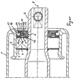
- the single FIGURE shows a longitudinal section through an embodiment of the shaft seal according to the invention.
- the representation of the figure is a partial longitudinal section in the axial direction of a conveyor roller with a substantially hollow cylindrical roller body 1 and an axle shaft 2 which is mounted on the roller body 1.
- the end of the reel body 1 is deformed inwardly to form a bearing seat 3 for a rolling bearing 4.
- To the enclosed by the roller body 1 cavity of the bearing area with the rolling bearing 4 with an annular bearing cap 5 is completed.
- the pointing in the opposite direction or the environment side of the storage area is completed by the shaft seal according to the invention.
- the shaft seal know an arranged on the axle 2 inner sealing element 6 on.
- the inner seal member 6 is composed of a first inner hollow cylinder and a second inner hollow cylinder which abuts against the outside of the first hollow cylinder.
- a first inner ring 7 is arranged, so that on both sides of the central axis 8, a substantially L-shaped longitudinal section or profile is formed.
- a second inner ring 9 is arranged such that between the first inner ring 7 and the second inner ring 9, a groove-shaped gap 10 is formed.
- a third inner ring 11 which has a smaller thickness than the second ring 9, is arranged as an extension thereof.
- the three inner rings 7, 9, 11 each have with their free end radially outward.
- a seal cover 12th At the side facing the environment of the inner seal member 6 is a seal cover 12th
- the first hollow cylinder is formed integrally with the first inner ring 7. Further, the second hollow cylinder is integrally formed together with the second and third inner rings 9, 11. It is clear that the entire inner sealing element 6 may be formed in one piece.
- the material for the inner seal member 6 may be a glass fiber reinforced polyamide, for example, PA66 GF30.
- An outer sealing member 13 is disposed on the reel body 1 and, in the illustrated example of a conveying roller, together with the reel body 1, performs a rotational movement relative to the axle shaft 2 and the inner sealing member 6.
- the outer sealing member 13 is composed of an annular member having a substantially Y-shaped profile in longitudinal section and a first outer ring 14.
- the first outer ring 14 is disposed adjacent to an arm of the Y and has with its free end radially inward.
- a second outer ring 15 is formed by the leg of the Y. Also, the second outer ring 15 has with its free end radially inward, i. to the central axis 8.
- the outwardly facing arm of the Y forms a third outer ring 16 which, in contrast to the first two inner rings 14 and 15 with its free end facing radially outward.
- the outer sealing element 13 is made of a relatively soft or abradable material, for example POM or polyacetate, compared to the material of the inner sealing element 6.
- the labyrinth gap of the shaft seal is preferably filled with a lubricant or sealant, for example a grease.
- a lubricant or sealant for example a grease.
- the roller body 1 eliminates the fat acting outward centrifugal force.
- The preferably relatively viscous fat settles and "flows" slowly in the shaft seal due to gravity down. That in the lower portion of the shaft seal, the grease seals the labyrinth gap in the space around the free end of the inner ring 7. In the upper part of the shaft seal, the grease fills the space around the free end of the second outer ring 15 and seals the labyrinth gap there. In this way, protection against ingress of dirt and moisture is both in operation and at standstill of the roller body 1 allows.
Landscapes
- Engineering & Computer Science (AREA)
- General Engineering & Computer Science (AREA)
- Mechanical Engineering (AREA)
- Sealing Using Fluids, Sealing Without Contact, And Removal Of Oil (AREA)
- Sealing Devices (AREA)
- Sealing With Elastic Sealing Lips (AREA)
- Rollers For Roller Conveyors For Transfer (AREA)
Abstract
Description
Die vorliegende Erfindung betrifft eine Wellendichtung mit einem an einer Achswelle angeordneten inneren Dichtungselement, das mindestens einen Ring aufweist, und einen an einem Rollenkörper angeordneten äußeren Dichtungselement, das mindestens einen Ring aufweist, der im Wesentlichen parallel zu den mindestens einen Ring des inneren Dichtungselementes ausgerichtet ist.The present invention relates to a shaft seal having an axle seal disposed on an inner seal member having at least one ring, and disposed on a roller body outer seal member having at least one ring which is aligned substantially parallel to the at least one ring of the inner seal member ,
Die vorliegende Erfindung betrifft ferner eine Rolle für Förderer, insbesondere Gurt-oder Bandförderer, mit einem hohlzylindrischen Rollenkörper und einer in mindestens zwei Lagern gelagerten Achswelle, wobei an den Lagern jeweils eine Wellendichtung angeordnet ist.The present invention further relates to a roller for conveyors, in particular belt or belt conveyor, with a hollow cylindrical roller body and a mounted in at least two bearings axle shaft, wherein a shaft seal is arranged on the bearings in each case.
Solche Rollen für einen Förderer, die mit mindestens zwei entsprechenden Wellendichtungen ausgestattet sind, sind hinreichend bekannt, beispielsweise aus der
Derartige Wellendichtungen werden, wenn die inneren und äußeren Dichtungselemente einander nicht berühren, allgemein als Labyrinthdichtung bezeichnet. Prinzipiell wird die Dichtwirkung zwischen einer in einem Gehäuse rotierenden Welle durch geeignete Anordnung der Ringe auf der Welle erzeugt, die in entsprechenden Nuten am feststehenden Gehäuse laufen. Hierdurch wird der Dichtweg um ein Vielfaches verlängert. Die Verlängerung des Dichtweges bewirkt einen Druckabbau durch die auftretende Reibung des in dem Dichtweg befindlichen Mediums, der so groß sein muss, dass am Ende des Dichtweges kein oder annähernd kein Druckunterschied mehr zum Druck außerhalb der Wellendichtung besteht.Such shaft seals, when the inner and outer seal members do not contact each other, are commonly referred to as a labyrinth seal. In principle, the sealing effect between a rotating shaft in a housing is generated by suitable arrangement of the rings on the shaft, which run in corresponding grooves on the fixed housing. As a result, the sealing path is extended by a multiple. The extension of the sealing path causes a pressure reduction due to the occurring friction of the medium located in the sealing path, which must be so large that at the end of the sealing path there is no or almost no pressure difference to the pressure outside of the shaft seal.
Der Dichtweg weist einander wechselweise abfolgend mehrere Kammern auf, die über jeweils einen Labyrinthspalt miteinander verbunden sind, die Drosselstellen bilden. Die in den Labyrinthspalten teilweise in kinetische Energie umgewandelte Druckenergie wird in den nachfolgenden Kammern abgesenkt, da sie teils durch Wirbelbildung, teils als Wärme aufgezehrt wird und somit der Druckenergie verloren geht. Eine Abfolge von mehrere hintereinander geschalteten Kammern und Labyrinthspalten senkt somit ein hohes Druckniveau vor der Wellendichtung auf ein tiefes Druckniveau dahinter ab.The sealing path has alternately successively a plurality of chambers, which are connected to each other via a labyrinth gap, forming the throttle points. The pressure energy partially converted into kinetic energy in the labyrinth gaps is lowered in the following chambers, since it is partly consumed by vortex formation, partly as heat, and thus the pressure energy is lost. A sequence of several chambers and labyrinth gaps connected in series thus reduces a high pressure level in front of the shaft seal to a low pressure level behind it.
Aufgrund des hohen Strömungswiderstandes in dem langen Labyrinthspalt kann nur eine geringe, tolerierbare Gas- oder Flüssigkeitsmenge durch die Labyrinthdichtung austreten. Eine absolute Dichtheit ist mit dieser berührungsfreien Konstruktion aber nicht möglich. Die austretende Fluidmenge kann weiter reduziert werden, indem die Breite des Labyrinth- bzw. Dichtspaltes relativ schmal ausgebildet ist.Due to the high flow resistance in the long labyrinth gap only a small, tolerable amount of gas or liquid can escape through the labyrinth seal. Absolute tightness is not possible with this non-contact design. The exiting amount of fluid can be further reduced by the width of the labyrinth or sealing gap is formed relatively narrow.
Der Labyrinth- bzw. Dichtspalt weist dabei üblicherweise seine geringste Breite zwischen den Stirnflächen der Ringe und den Nuten auf. Die Dichtungswirkung kann aber, wie zum Beispiel in der
In dem Fall einer feststehenden Welle, um die herum ein Rollenkörper rotiert, führt eine Belastung der Rolle durch ein Fördergut zu Verformungen und Geometrieveränderungen sowohl des Rollenkörpers als auch der Wellendichtung. Bei einer aufliegenden Last und einer vertikal nach unten wirkenden Kraft, beispielsweise die Schwerkraft des Fördergutes, wird das äußere Dichtelement oberhalb der Achswelle in die Richtung des inneren Dichtelementes geneigt. Unterhalb der Achswelle wird das äußere Dichtungselement von dem inneren Dichtungselement fortgeneigt.In the case of a fixed shaft, around which a reel body rotates, loading of the reel by a conveyed material leads to deformations and changes in geometry of both the reel body and the shaft seal. With an overlying load and a vertical downward force, such as the gravity of the material to be conveyed, the outer sealing element is inclined above the axle shaft in the direction of the inner sealing element. Below the axle shaft, the outer seal member is inclined away from the inner seal member.
Daraus resultiert, dass die Dichtungselemente oberhalb der Achswelle in Kontakt miteinander kommen und aneinander reiben, während unterhalb der Achswelle das Spaltmaß sich vergrößert. Dies führt bei Rotation zu einem Pumpeffekt, so dass Luftfeuchtigkeit und/oder Staub über den äußersten Labyrinthspalt in den Dichtweg hineingezogen werden können. Durch die Spaltmaßveränderung und insbesondere den Kontakt oberhalb der Achswelle entsteht eine Bremswirkung und ein Reibschluss, so dass die Wellendichtung vorzeitigt verschleißt.As a result, the sealing elements above the axle shaft come into contact with each other and rub against each other, while below the axle shaft, the gap increases. This results in a pumping effect during rotation, so that humidity and / or dust can be drawn into the sealing path via the outermost labyrinth gap. Due to the Spaltmaßveränderung and in particular the contact above the axle shaft creates a braking effect and a frictional engagement, so that the shaft seal wears prematurely.
Vor diesem Hintergrund ist es die Aufgabe der vorliegenden Erfindung, eine verbesserte Wellendichtung mit hoher Zuverlässigkeit und langer Lebensdauer auch bei vertikaler Belastung anzugeben.Against this background, it is the object of the present invention to provide an improved shaft seal with high reliability and long life even with vertical load.
Diese Aufgabe wird durch eine Wellendichtung mit den Merkmalen des Anspruchs 1 und eine Rolle für einen Förderer mit den Merkmalen gemäß Anspruch 2 gelöst.This object is achieved by a shaft seal with the features of claim 1 and a roller for a conveyor with the features of claim 2.
Erfindungsgemäß ist bei einer Wellendichtung der eingangs beschriebenen Art vorgesehen, dass an einem Ring eines der beiden Dichtungselemente ein ringförmig umlaufender zu einem Ring des anderen Dichtungselementes weisender Vorsprung vorgesehen ist. Ferner ist erfindungsgemäß vorgesehen, dass der Vorsprung bei einem Zusammenbau der Wellendichtung in Kontakt mit dem Ring des anderen Dichtungselementes ist und nach Beginn einer Rotationsbewegung der Achswelle und/oder des Rollenkörpers sich abschleift, bis ein schmaler Ringspalt zwischen dem Vorsprung und dem Ring des anderen Dichtungselementes ausgebildet ist.According to the invention, it is provided in a shaft seal of the type described above that a ring-shaped circumferential to a ring of the other sealing element facing projection is provided on a ring of one of the two sealing elements. It is further provided according to the invention that the projection in an assembly of the shaft seal in contact with the ring of the other sealing element and abrades after the start of a rotational movement of the axle shaft and / or the roller body, to a narrow annular gap between the projection and the ring of the other sealing element is trained.
Die wesentliche Idee besteht darin, dass die Wellendichtung zunächst eine Kontaktdichtung ist, die eine Soll-Verschleißstelle aufweist. Nach einer bestimmten Zeitdauer der Rotationsbewegung ist der Vorsprung zum Teil abgeschliffen Zwischen dem Vorsprung und dem gegenüberliegenden Ring wird folglich ein schmaler Ringspalt gebildet, der im gesamten Umfang der Wellendichtung berührungsfrei ist. Somit ist nach einer bestimmten "Einrollzeit" eine berührungsfreie Labyrinthdichtung ausgebildet. Der Vorsprung wird nur in dem Maß abgeschliffen, wie es für einen berührungsfreien Betrieb erforderlich ist, da das Abschleifen genau dann automatisch beendet wird. Ein vergleichsweise schmaler Ringspalt ist bei üblichen Wellendichtungen nur mit einer hochpräzisen Fertigungs- und Montagegenauigkeit möglich, die die Herstellungskosten für eine derartige Wellendichtung erheblich ansteigen lässt.The essential idea is that the shaft seal is initially a contact seal having a desired wear point. After a certain period of the rotational movement, the projection is partially ground between the projection and the opposite ring thus a narrow annular gap is formed, which is non-contact in the entire circumference of the shaft seal. Thus, after a certain "curl time" is a non-contact labyrinth seal educated. The projection is ground down only to the extent required for non-contact operation, since the abrading is terminated automatically then. A comparatively narrow annular gap is possible with conventional shaft seals only with a high-precision manufacturing and assembly accuracy, which can increase the manufacturing cost of such a shaft seal considerably.
Die erfindungsgemäße Rolle für einen Förderer weist eine erfindungsgemäße Wellendichtung auf. Sobald die Wellendichtung berührungsfrei läuft, ist eine gleichmäßige Rotation der Förderrolle gewährleistet. Dies führt zu einem deutlich reduzierten Verschleiß des Rollenmantels, da aufgrund der gleichmäßigen Geschwindigkeit ein Anheben des Gurtes (bei einem Gurtförderer) und anschließendes herunterfallen vermieden wird. Ferner ist gerade bei Förderanlagen mit einer Vielzahl an Förderrollen, um eine bis zu mehrere Kilometer lange Förderstrecke zu bilden, wichtig, dass die Herstellung der Rollen inklusive der Abdichtungen preiswert möglich ist und die Rollen eine hohe Lebenszeit aufweisen.The roller according to the invention for a conveyor has a shaft seal according to the invention. Once the shaft seal runs without contact, a uniform rotation of the conveyor roller is ensured. This leads to a significantly reduced wear of the roller shell, since due to the uniform speed lifting the belt (in a belt conveyor) and subsequent falling is avoided. Further, especially in conveyor systems with a variety of conveyor rollers to form a conveyor belt up to several kilometers long, it is important that the production of the rollers including the seals is inexpensive and the rollers have a long service life.
Damit die Reibung gerade zu Beginn der Rotationsbewegung keine allzu große Bremswirkung entfaltet, verjüngt sich der Vorsprung bevorzugt. Der spitzförmig zulaufende Vorsprung bildet einen Kompromiss zwischen der Forderung einer geringen Reibung und einer ausreichenden Stabilität und der Abschliff bildet eine stumpfe Spitze an dem Vorsprung aus.So that the friction does not develop too much braking at the beginning of the rotational movement, the projection preferably tapers. The tapered projection is a compromise between the requirement of low friction and sufficient stability and the cut forms a blunt tip on the projection.
Eine vorteilhafte Ausgestaltung der erfindungsgemäßen Wellendichtung sieht vor, dass die Achswelle als Stator und der Rollenkörper als Rotor vorgesehen ist.An advantageous embodiment of the shaft seal according to the invention provides that the axle shaft is provided as a stator and the roller body as a rotor.
Vorteilhafterweise ist vorgesehen, dass in der Wellendichtung ein Dichtweg vorgesehen ist, bei dem von zwei jeweils gegenüberliegenden Begrenzungswänden eine dem inneren Dichtungselement und die andere dem äußeren Dichtungselement zugeordnet ist.Advantageously, it is provided that in the shaft seal a sealing path is provided, in which is assigned by the two opposing boundary walls, one the inner seal member and the other the outer seal member.
Um eine optimale Verlängerung des Dichtweges zu erzielen, ist bevorzugt vorgesehen, dass die Ringe des inneren Dichtungselementes und die Ringe des äußeren Dichtungselementes in Axialrichtung der Achswelle einander abwechselnd angeordnet sind.In order to achieve an optimal extension of the sealing path, it is preferably provided that the rings of the inner sealing element and the rings of the outer sealing element are arranged alternately in the axial direction of the axle shaft.
Ferner ist bei einer erfindungsgemäßen Wellendichtung bevorzugt, dass bei mehreren vorgesehenen Vorsprüngen diese nur einem der beiden Dichtungselemente zugeordnet sind. Dann kann durch eine geeignete, unterschiedliche Materialauswahl für die beiden Dichtungselemente ein Abschleifen der Vorsprünge ohne eine Beschädigung der gegenüberliegenden Ringe sichergestellt werden.Furthermore, in the case of a shaft seal according to the invention, it is preferred that in the case of several projections provided these are assigned to only one of the two sealing elements. Then, by a suitable, different choice of material for the two sealing elements, a grinding of the projections can be ensured without damaging the opposing rings.
Für einen vereinfachten Aufbau und eine zuverlässige Montage der Wellendichtung sind vorteilhafterweise das innere Dichtungselement und/oder das äußere Dichtungselement jeweils einstückig vorgesehen.For a simplified construction and reliable installation of the shaft seal, the inner sealing element and / or the outer sealing element are advantageously provided in one piece.
Da die erfindungsgemäße Wellendichtung auch unter einer Belastung zuverlässig funktioniert, kann sie bevorzugt für eine Rolle eines Förderers, insbesondere eines Gurt- oder Bandförderers, Verwendung finden.Since the shaft seal according to the invention also works reliably under a load, it can preferably be used for a roller of a conveyor, in particular a belt or belt conveyor.
Nachfolgend wird die Erfindung anhand der detaillierten Beschreibung unter Bezug auf die beigefügte Zeichnung beispielhaft näher erläutert.The invention will be explained in more detail by way of example with reference to the detailed description with reference to the attached drawing.
Die einzige Figur zeigt einen Längsschnitt durch ein Ausführungsbeispiel der erfindungsgemäßen Wellendichtung. Die Darstellung der Figur ist ein teilweiser Längsschnitt in Axialrichtung einer Förderrolle mit einem im Wesentlichen hohlzylindrischen Rollenkörper 1 und einer Achswelle 2, die an dem Rollenkörper 1 gelagert ist. In der Figur ist nur eine Seite der Förderrolle gezeigt und üblicherweise ist die gegenüberliegende Seite symmetrisch hierzu ausgebildet. Das Ende des Rollenkörpers 1 ist nach innen umgeformt, um einen Lagersitz 3 für ein Wälzlager 4 zu bilden. Zu dem von dem Rollenkörper 1 umschlossenen Hohlraum ist der Lagerbereich mit dem Wälzlager 4 mit einem ringförmigen Lagerdeckel 5 abgeschlossen. Die in die entgegengesetzte Richtung bzw. zur Umgebung weisende Seite des Lagerbereiches ist durch die erfindungsgemäße Wellendichtung abgeschlossen.The single FIGURE shows a longitudinal section through an embodiment of the shaft seal according to the invention. The representation of the figure is a partial longitudinal section in the axial direction of a conveyor roller with a substantially hollow cylindrical roller body 1 and an axle shaft 2 which is mounted on the roller body 1. In the figure, only one side of the conveyor roller is shown and usually the opposite side is formed symmetrically thereto. The end of the reel body 1 is deformed inwardly to form a bearing seat 3 for a rolling bearing 4. To the enclosed by the roller body 1 cavity of the bearing area with the rolling bearing 4 with an
Die Wellendichtung weißt ein an der Achswelle 2 angeordnetes inneres Dich-tungselement 6 auf. Das innere Dichtungselement 6 ist aus einem ersten inneren Hohlzylinder und einem zweiten inneren Hohlzylinder zusammengesetzt, der an der Außenseite des ersten Hohlzylinders anliegt. An dem ersten Hohlzylinder ist ein erster innerer Ring 7 angeordnet, so dass auf beiden Seiten der Mittelachse 8 ein im Wesentlichen L-förmiger Längsschnitt bzw. Profil gebildet ist. An dem zweiten Hohlzylinder ist ein zweiter innerer Ring 9 derart angeordnet, dass zwischen dem ersten inneren Ring 7 und dem zweiten inneren Ring 9 ein Nut-förmiger Zwischenraum 10 entsteht.The shaft seal know an arranged on the axle 2
An dem zweiten inneren Ring 9 ist als Verlängerung desselben ein dritter innerer Ring 11 angeordnet, der eine geringere Dicke als der zweite Ring 9 aufweist. Die drei inneren Ringe 7, 9, 11 weisen jeweils mit ihrem freien Ende nach radial außen. An der zur Umgebung zeigenden Seite des inneren Dichtungselementes 6 befindet sich ein Dichtungsdeckel 12.On the second inner ring 9, a third
In dem dargestellten Ausführungsbeispiel ist der erste Hohlzylinder einstückig mit dem ersten inneren Ring 7 ausgebildet. Ferner ist der zweite Hohlzylinder zusammen mit dem zweiten und dritten inneren Ring 9, 11 einstückig ausgebil-det. Es ist klar, dass auch das gesamte innere Dichtungselement 6 einstückig ausgebildet sein kann. Das Material für das innere Dichtungselement 6 kann ein glasfaserverstärktes Polyamid, beispielsweise PA66 GF30, sein.In the illustrated embodiment, the first hollow cylinder is formed integrally with the first inner ring 7. Further, the second hollow cylinder is integrally formed together with the second and third
Ein äußeres Dichtungselement 13 ist an dem Rollenkörper 1 angeordnet und führt in dem dargestellten Beispiel einer Förderrolle gemeinsam mit dem Rollenkörper 1 eine Rotationsbewegung relativ zu der Achswelle 2 und dem inneren Dichtungselement 6 aus. Das äußere Dichtungselement 13 ist aus einem ringförmigen Element mit einem im Wesentlichen Y-förmigen Profil im Längsschnitt und einem ersten äußeren Ring 14 zusammengesetzt.An
Der erste äußere Ring 14 ist an einem Arm des Y angrenzend angeordnet und weist mit seinem freien Ende nach radial innen. Ein zweiter äußerer Ring 15 wird durch das Bein des Y gebildet. Auch der zweite äußere Ring 15 weist mit seinem freien Ende nach radial innen, d.h. zur Mittelachse 8. Der zur Umgebung weisende Arm des Y bildet einen dritten äußeren Ring 16, der im Gegensatz zu den ersten beiden inneren Ringen 14 und 15 mit seinem freien Ende nach radial außen weist.The first outer ring 14 is disposed adjacent to an arm of the Y and has with its free end radially inward. A second
An den drei äußeren Ringen 14, 15 und 16 ist jeweils ein Vorsprung 17, 18 und 19 vorgesehen. Dabei ist der spitzförmig zulaufende Vorsprung 17 des ersten äußeren Ringes 14 zu dem ersten inneren Ring 17 hin ausgerichtet. Der zweite Vorsprung 18 an dem zweiten äußeren Ring 15 ist auf den zweiten inneren Ring 9 weisend ausgerichtet. Schließlich ist der dritte Vorsprung 19 an dem dritten äußeren Ring 16 derart angeordnet, dass seine Spitze zu dem dritten inneren Ring 11 zeigt. In dem dargestellten Beispiel ist das äußere Dichtungselement 13 aus einem im Vergleich zu dem Material des inneren Dichtungselementes 6 relativ weichen bzw. abschleifbaren Material, beispielsweise POM bzw. Polyazetat, hergestellt.At the three
Bei der Montage der Wellendichtung sind die Vorsprünge 17, 18 bzw. 19 in Reibkontakt mit dem ersten inneren Ring 7, dem zweiten inneren Ring 9 bzw. dem dritten inneren Ring 11. Nach Aufnahme der Rotationsbewegung des Rollenkörpers 1 bezogen auf die Achswelle 2 reibt das äußere Dichtungselement 13 an dem inneren Dichtungselement 6 und es werden die jeweiligen Spitzen der Vorsprünge 17, 18 und 19 aufgrund der Reibung abgeschliffen, bis jeweils ein schmaler Ringspalt ausgebildet ist. Nachdem die Ringspalte gebildet worden sind, läuft die Wellendichtung berührungsfrei. Dieser "Einroll"-Vorgang bis die Wellendichtung berührungsfrei läuft, dauert einige wenige Tage, erfahrungsgemäß in etwa zwei Tage.When mounting the shaft seal, the
Es ist klar, dass in der Einrollzeit eine höhere Leistung für die Rotation der Förderrolle aufgebracht werden muss, da die Reibverlustenergie ausgeglichen werden muss. Sobald die Ringspalte gebildet sind, wird eine entsprechend geringe Leistung des Antriebssystems benötigt.It is clear that in the retraction time, a higher power for the rotation of the conveyor roller must be applied, since the Reibverlustenergie must be compensated. Once the annular gaps are formed, a correspondingly low power of the drive system is required.
Wenn auf den Rollenkörper 1 eine Last, beispielsweise durch ein Fördergut, aufgebracht wird, bewirkt die Verformung der Rolle ein Verkippen bzw. Neigen der äußeren Ringe 14, 15 und 16 in Bezug auf die inneren Ringe 7, 9 und 11. In diesem Fall werden die Vorsprünge 17, 18 und 19 weiter abgeschliffen, bis wieder ein berührungsfreier Lauf stattfinden kann. Der Wechsel von einem belasteten Rollenkörper 1 zu einem unbelasteten Rollenkörper 1 bewirkt dann lediglich eine Veränderung des Spaltringes, ohne dass ein Reibkontakt hergestellt wird. Dadurch wird der so genannte Pumpeffekt vermieden.When a load is applied to the reel body 1, for example by a conveyed material, the deformation of the roller causes tilting of the
Der Labyrinthspalt der Wellendichtung ist vorzugsweise mit einem Schmier- bzw. Dichtmittel, beispielsweise ein Fett, gefüllt. Durch die Rotation des Rollenkörpers 1 wird das Fett nach radial außen geschleudert und sammelt sich ins-besondere in dem Labyrinthspalt in den Raum um das freie Ende des ersten inneren Ringes 7 herum an. Dadurch wird der Labyrinthspalt zwischen dem ersten inneren Ring 7 und dem äußeren Dichtungselement 13 wirksam abgedichtet.The labyrinth gap of the shaft seal is preferably filled with a lubricant or sealant, for example a grease. By the rotation of the roller body 1, the fat is thrown radially outward and accumulates ins-particular in the labyrinth gap in the space around the free end of the first inner ring 7 around. This will make the labyrinth gap between the first inner ring 7 and the outer sealing
Bei einem Stillstand des Rollenkörpers 1 entfällt die das Fett nach außen wirkende Schleuderkraft. Das vorzugsweise relativ zähe Fett setzt sich ab und "fließt" langsam in der Wellendichtung aufgrund der Schwerkraft nach unten. D.h. im unteren Anteil der Wellendichtung dichtet das Fett den Labyrinthspalt in dem Raum um das freie Ende des inneren Ringes 7 ab. Im oberen Bereich der Wellendichtung füllt das Fett den Raum um das freie Ende des zweiten äußeren Ringes 15 auf und dichtet den Labyrinthspalt dort ab. Auf diese Weise ist ein Schutz vor eindringendem Schmutz und eindringender Feuchtigkeit sowohl im Betrieb als auch im Stillstand des Rollenkörpers 1 ermöglicht.At a standstill of the roller body 1 eliminates the fat acting outward centrifugal force. The preferably relatively viscous fat settles and "flows" slowly in the shaft seal due to gravity down. That in the lower portion of the shaft seal, the grease seals the labyrinth gap in the space around the free end of the inner ring 7. In the upper part of the shaft seal, the grease fills the space around the free end of the second
Claims (8)
- Shaft seal for use with a roller of a conveyor, in particular a belt or band conveyor with an inner sealing element (6) arranged on an axle shaft (2), which inner sealing element has at least one ring (7, 9, 11), and an outer sealing element arranged on a roller body (1), which outer sealing element has at least one ring (14,15,16), which is aligned substantially parallel to the at least one ring (7, 9, 11) of the inner sealing element (6), characterised in that an annular revolving projection (17, 18, 19) is provided on one of the rings (14, 15, 16) of one of the two sealing elements (13), pointing to a ring (7, 9,11) of the other sealing element (6), which projection is in contact with the ring (7, 9, 11) of the other sealing element in an assembly of the shaft seal, and which, after the start of a rotational movement of the axle shaft (2) and/or the roller body (1) is abraded, until a narrower annular gap is formed between the projection (17, 18, 19) and the ring (7, 9, 11) of the other sealing element (6).
- Roller for a conveyor, in particular a belt of band conveyor, with a hollow cylindrical roller body (1) and an axle shaft (2) mounted in at least two bearings (4), characterised in that a shaft seal according to claim 1 is arranged on the bearings in each case.
- Roller according to claim 2, characterised in that the projection (17, 18, 19) tapers.
- Roller according to claim 2 or 3, characterised in that the axle shaft (2) is provided as a stator and the roller body (1) as a rotor.
- Roller according to one or more of claims 2 to 4, characterised by a seal path, in which one of two opposed limiting walls is associated with the inner sealing element (6) and the other with the outer sealing element (13).
- Roller according to one or more of claims 2 to 5, characterised in that the rings (7, 9,11) of the inner sealing element (6) and the rings (14, 15, 16) of the outer sealing element (13) are arranged alternately with each other in the axial direction of the axle shaft (2).
- Roller according to one or more of claims 2 to 6, characterised in that with a plurality of projections (17, 18, 19), these are associated with only one of the two sealing elements (6,13).
- Roller according to one or more of claims 2 to 7, characterised in that the inner sealing element (6) and/or the outer sealing element (13) in each case are provided in one piece.
Priority Applications (1)
| Application Number | Priority Date | Filing Date | Title |
|---|---|---|---|
| PL07722423T PL1893877T3 (en) | 2006-05-22 | 2007-05-11 | Shaft seal |
Applications Claiming Priority (2)
| Application Number | Priority Date | Filing Date | Title |
|---|---|---|---|
| DE102006024154A DE102006024154B3 (en) | 2006-05-22 | 2006-05-22 | Shaft seal and roller for a conveyer has inner and outer seals with rings and a projection at one ring that wears on an opposite ring on rotation to reduce the gap |
| PCT/DE2007/000875 WO2007134576A1 (en) | 2006-05-22 | 2007-05-11 | Shaft seal |
Publications (2)
| Publication Number | Publication Date |
|---|---|
| EP1893877A1 EP1893877A1 (en) | 2008-03-05 |
| EP1893877B1 true EP1893877B1 (en) | 2011-07-06 |
Family
ID=38190270
Family Applications (1)
| Application Number | Title | Priority Date | Filing Date |
|---|---|---|---|
| EP07722423A Active EP1893877B1 (en) | 2006-05-22 | 2007-05-11 | Shaft seal |
Country Status (12)
| Country | Link |
|---|---|
| EP (1) | EP1893877B1 (en) |
| AT (1) | ATE515643T1 (en) |
| BR (1) | BRPI0706298A2 (en) |
| CA (1) | CA2640477C (en) |
| DE (1) | DE102006024154B3 (en) |
| EA (1) | EA016414B1 (en) |
| ES (1) | ES2369192T3 (en) |
| PL (1) | PL1893877T3 (en) |
| RS (1) | RS52005B (en) |
| UA (1) | UA92799C2 (en) |
| WO (1) | WO2007134576A1 (en) |
| ZA (1) | ZA200806834B (en) |
Families Citing this family (7)
| Publication number | Priority date | Publication date | Assignee | Title |
|---|---|---|---|---|
| US8844935B2 (en) * | 2011-04-13 | 2014-09-30 | Gamesa Innovation & Technology, S.L. | Seal arrangement |
| RU2557586C1 (en) * | 2014-01-21 | 2015-07-27 | Государственное предприятие "Украинский научно-технический центр металлургической промышленности "Энергосталь" (ГП "УкрНТЦ "Энергосталь") | Gas scrubber |
| FI127009B (en) * | 2014-03-27 | 2017-09-15 | Andritz Oy | Tilt filter and procedure in connection with the tint filter |
| CN104329467B (en) * | 2014-10-16 | 2017-01-18 | 武汉新置密封科技有限公司 | S-shaped multiple labyrinth seal device |
| CN104315150B (en) * | 2014-10-16 | 2017-02-15 | 武汉新置密封科技有限公司 | Rotary lip labyrinth sealing device |
| CA3039360C (en) | 2016-10-03 | 2024-01-16 | Superior Industries, Inc. | Conveyor idler seal apparatus, systems, and methods |
| CN109505986B (en) * | 2018-12-28 | 2024-04-09 | 张家港市兰航机械有限公司 | Sealing structure of side press roller |
Family Cites Families (8)
| Publication number | Priority date | Publication date | Assignee | Title |
|---|---|---|---|---|
| DE1143068B (en) * | 1961-03-06 | 1963-01-31 | Hirth Motoren K G | Sealing of rotating parts |
| FR1359386A (en) * | 1963-03-29 | 1964-04-24 | Rotating seal | |
| CH508192A (en) | 1969-05-08 | 1971-05-31 | Oerlikon Buehrle Ag | Tank turret with at least one automatic firearm stored outside the tank turret |
| DE2163734C3 (en) * | 1971-12-22 | 1974-10-31 | J.M. Voith Gmbh, 7920 Heidenheim | Labyrinth seal for sealing two components that can be rotated relative to one another |
| US4452497A (en) * | 1982-09-20 | 1984-06-05 | Rockwell International Corporation | Grease seal for bearing arrangement |
| SK277704B6 (en) * | 1992-04-01 | 1994-07-06 | Milan Bouchal | Roller for belt conveyer |
| BR9805787C1 (en) | 1998-12-21 | 2004-07-13 | Svedala Ltda | Conveyor Belt Roll |
| DE10047307A1 (en) * | 2000-09-25 | 2002-08-01 | Alstom Switzerland Ltd | sealing arrangement |
-
2006
- 2006-05-22 DE DE102006024154A patent/DE102006024154B3/en not_active Expired - Fee Related
-
2007
- 2007-05-11 PL PL07722423T patent/PL1893877T3/en unknown
- 2007-05-11 AT AT07722423T patent/ATE515643T1/en active
- 2007-05-11 ES ES07722423T patent/ES2369192T3/en active Active
- 2007-05-11 WO PCT/DE2007/000875 patent/WO2007134576A1/en active Application Filing
- 2007-05-11 EA EA200802249A patent/EA016414B1/en not_active IP Right Cessation
- 2007-05-11 RS RS20110426A patent/RS52005B/en unknown
- 2007-05-11 ZA ZA200806834A patent/ZA200806834B/en unknown
- 2007-05-11 EP EP07722423A patent/EP1893877B1/en active Active
- 2007-05-11 CA CA2640477A patent/CA2640477C/en not_active Expired - Fee Related
- 2007-05-11 BR BRPI0706298-2A patent/BRPI0706298A2/en not_active IP Right Cessation
- 2007-11-05 UA UAA200814561A patent/UA92799C2/en unknown
Also Published As
| Publication number | Publication date |
|---|---|
| ZA200806834B (en) | 2009-12-30 |
| PL1893877T3 (en) | 2011-12-30 |
| CA2640477C (en) | 2012-07-03 |
| BRPI0706298A2 (en) | 2011-03-22 |
| ATE515643T1 (en) | 2011-07-15 |
| ES2369192T3 (en) | 2011-11-28 |
| EA200802249A1 (en) | 2009-06-30 |
| EA016414B1 (en) | 2012-04-30 |
| WO2007134576A1 (en) | 2007-11-29 |
| CA2640477A1 (en) | 2007-11-29 |
| EP1893877A1 (en) | 2008-03-05 |
| DE102006024154B3 (en) | 2007-07-19 |
| RS52005B (en) | 2012-04-30 |
| UA92799C2 (en) | 2010-12-10 |
Similar Documents
| Publication | Publication Date | Title |
|---|---|---|
| EP1893877B1 (en) | Shaft seal | |
| EP3014149B1 (en) | Radial shaft seal | |
| EP3607220A1 (en) | Tapered roller bearing and wind turbine | |
| DE3828363A1 (en) | SEALING DEVICE | |
| DE102009014922A1 (en) | Greased double row rolling bearing and bearing system with such a rolling bearing and a lubricating device | |
| EP3127221B1 (en) | Device for lubricating the rolling bearing of an electrical motor | |
| DE102015102867A1 (en) | roller bearing | |
| DE102009034798A1 (en) | Rolling bearings, in particular single row deep groove ball bearings for a dual mass flywheel in a motor vehicle | |
| WO2009156260A1 (en) | Cassette seal | |
| WO2011138107A1 (en) | Rolling bearing having an integrated seal | |
| DE2350630A1 (en) | HYDRODYNAMIC SHAFT SEAL | |
| DE102018006945B3 (en) | Radial shaft seal | |
| DE102014219700A1 (en) | Gasket in a bearing and method for a wear-reducing operation of a seal in a bearing | |
| EP2899307B1 (en) | Washing unit for a washing machine | |
| DE3311121C2 (en) | Non-contact seal | |
| DE102016118057A1 (en) | Rolling bearing, wind turbine and method for operating a rolling bearing | |
| DE102016118052A1 (en) | Rolling bearing, sealing element, wind turbine and method for operating a rolling bearing | |
| DE102019212629A1 (en) | Rotor bearing for a wind turbine and wind turbine | |
| WO2018192846A1 (en) | Shaft seal | |
| EP0276441B1 (en) | Oil seal | |
| DE202006019932U1 (en) | Shaft seal has projection with assembling of shaft seal which is in contact with ring of other seal element, and projection strips after beginning of rotation movement of arbor or role body | |
| EP3492785B1 (en) | Sealing ring and seal arrangement comprising such a sealing ring | |
| DE102009005775B4 (en) | Bearing seal arrangement | |
| DE102018105088B4 (en) | Water pump with sealing arrangement for roller bearings | |
| DE102018125777A1 (en) | Rolling bearing and seal for a rolling bearing |
Legal Events
| Date | Code | Title | Description |
|---|---|---|---|
| PUAI | Public reference made under article 153(3) epc to a published international application that has entered the european phase |
Free format text: ORIGINAL CODE: 0009012 |
|
| 17P | Request for examination filed |
Effective date: 20071229 |
|
| AK | Designated contracting states |
Kind code of ref document: A1 Designated state(s): AT BE BG CH CY CZ DE DK EE ES FI FR GB GR HU IE IS IT LI LT LU LV MC MT NL PL PT RO SE SI SK TR |
|
| AX | Request for extension of the european patent |
Extension state: AL BA HR MK YU |
|
| RAX | Requested extension states of the european patent have changed |
Extension state: HR Extension state: AL Extension state: MK Extension state: RS Extension state: BA |
|
| RAP1 | Party data changed (applicant data changed or rights of an application transferred) |
Owner name: SANDVIK MINING AND CONSTRUCTION SUPPLY GMBH |
|
| RAX | Requested extension states of the european patent have changed |
Extension state: HR Extension state: RS Payment date: 20080411 Extension state: BA Extension state: AL Extension state: MK |
|
| RAX | Requested extension states of the european patent have changed |
Extension state: RS Payment date: 20080411 |
|
| 17Q | First examination report despatched |
Effective date: 20090910 |
|
| GRAP | Despatch of communication of intention to grant a patent |
Free format text: ORIGINAL CODE: EPIDOSNIGR1 |
|
| GRAS | Grant fee paid |
Free format text: ORIGINAL CODE: EPIDOSNIGR3 |
|
| GRAA | (expected) grant |
Free format text: ORIGINAL CODE: 0009210 |
|
| AK | Designated contracting states |
Kind code of ref document: B1 Designated state(s): AT BE BG CH CY CZ DE DK EE ES FI FR GB GR HU IE IS IT LI LT LU LV MC MT NL PL PT RO SE SI SK TR |
|
| AX | Request for extension of the european patent |
Extension state: RS |
|
| REG | Reference to a national code |
Ref country code: GB Ref legal event code: FG4D Free format text: NOT ENGLISH |
|
| REG | Reference to a national code |
Ref country code: CH Ref legal event code: EP |
|
| REG | Reference to a national code |
Ref country code: IE Ref legal event code: FG4D Free format text: LANGUAGE OF EP DOCUMENT: GERMAN |
|
| REG | Reference to a national code |
Ref country code: DE Ref legal event code: R096 Ref document number: 502007007609 Country of ref document: DE Effective date: 20110908 |
|
| REG | Reference to a national code |
Ref country code: RO Ref legal event code: EPE |
|
| REG | Reference to a national code |
Ref country code: NL Ref legal event code: T3 |
|
| REG | Reference to a national code |
Ref country code: SE Ref legal event code: TRGR |
|
| REG | Reference to a national code |
Ref country code: GR Ref legal event code: EP Ref document number: 20110402322 Country of ref document: GR Effective date: 20111013 |
|
| REG | Reference to a national code |
Ref country code: ES Ref legal event code: FG2A Ref document number: 2369192 Country of ref document: ES Kind code of ref document: T3 Effective date: 20111128 |
|
| PG25 | Lapsed in a contracting state [announced via postgrant information from national office to epo] |
Ref country code: SI Free format text: LAPSE BECAUSE OF FAILURE TO SUBMIT A TRANSLATION OF THE DESCRIPTION OR TO PAY THE FEE WITHIN THE PRESCRIBED TIME-LIMIT Effective date: 20110706 |
|
| REG | Reference to a national code |
Ref country code: PL Ref legal event code: T3 |
|
| PG25 | Lapsed in a contracting state [announced via postgrant information from national office to epo] |
Ref country code: PT Free format text: LAPSE BECAUSE OF FAILURE TO SUBMIT A TRANSLATION OF THE DESCRIPTION OR TO PAY THE FEE WITHIN THE PRESCRIBED TIME-LIMIT Effective date: 20111107 Ref country code: LT Free format text: LAPSE BECAUSE OF FAILURE TO SUBMIT A TRANSLATION OF THE DESCRIPTION OR TO PAY THE FEE WITHIN THE PRESCRIBED TIME-LIMIT Effective date: 20110706 Ref country code: IS Free format text: LAPSE BECAUSE OF FAILURE TO SUBMIT A TRANSLATION OF THE DESCRIPTION OR TO PAY THE FEE WITHIN THE PRESCRIBED TIME-LIMIT Effective date: 20111106 |
|
| REG | Reference to a national code |
Ref country code: IE Ref legal event code: FD4D |
|
| PG25 | Lapsed in a contracting state [announced via postgrant information from national office to epo] |
Ref country code: LV Free format text: LAPSE BECAUSE OF FAILURE TO SUBMIT A TRANSLATION OF THE DESCRIPTION OR TO PAY THE FEE WITHIN THE PRESCRIBED TIME-LIMIT Effective date: 20110706 Ref country code: CY Free format text: LAPSE BECAUSE OF FAILURE TO SUBMIT A TRANSLATION OF THE DESCRIPTION OR TO PAY THE FEE WITHIN THE PRESCRIBED TIME-LIMIT Effective date: 20110706 |
|
| REG | Reference to a national code |
Ref country code: HU Ref legal event code: AG4A Ref document number: E012419 Country of ref document: HU |
|
| PG25 | Lapsed in a contracting state [announced via postgrant information from national office to epo] |
Ref country code: IE Free format text: LAPSE BECAUSE OF FAILURE TO SUBMIT A TRANSLATION OF THE DESCRIPTION OR TO PAY THE FEE WITHIN THE PRESCRIBED TIME-LIMIT Effective date: 20110706 Ref country code: SK Free format text: LAPSE BECAUSE OF FAILURE TO SUBMIT A TRANSLATION OF THE DESCRIPTION OR TO PAY THE FEE WITHIN THE PRESCRIBED TIME-LIMIT Effective date: 20110706 |
|
| PLBE | No opposition filed within time limit |
Free format text: ORIGINAL CODE: 0009261 |
|
| STAA | Information on the status of an ep patent application or granted ep patent |
Free format text: STATUS: NO OPPOSITION FILED WITHIN TIME LIMIT |
|
| PG25 | Lapsed in a contracting state [announced via postgrant information from national office to epo] |
Ref country code: IT Free format text: LAPSE BECAUSE OF FAILURE TO SUBMIT A TRANSLATION OF THE DESCRIPTION OR TO PAY THE FEE WITHIN THE PRESCRIBED TIME-LIMIT Effective date: 20110706 Ref country code: EE Free format text: LAPSE BECAUSE OF FAILURE TO SUBMIT A TRANSLATION OF THE DESCRIPTION OR TO PAY THE FEE WITHIN THE PRESCRIBED TIME-LIMIT Effective date: 20110706 |
|
| 26N | No opposition filed |
Effective date: 20120411 |
|
| PG25 | Lapsed in a contracting state [announced via postgrant information from national office to epo] |
Ref country code: DK Free format text: LAPSE BECAUSE OF FAILURE TO SUBMIT A TRANSLATION OF THE DESCRIPTION OR TO PAY THE FEE WITHIN THE PRESCRIBED TIME-LIMIT Effective date: 20110706 |
|
| PGFP | Annual fee paid to national office [announced via postgrant information from national office to epo] |
Ref country code: TR Payment date: 20120508 Year of fee payment: 6 Ref country code: DE Payment date: 20120604 Year of fee payment: 6 Ref country code: CZ Payment date: 20120503 Year of fee payment: 6 Ref country code: BG Payment date: 20120523 Year of fee payment: 6 Ref country code: NL Payment date: 20120523 Year of fee payment: 6 Ref country code: HU Payment date: 20120509 Year of fee payment: 6 |
|
| REG | Reference to a national code |
Ref country code: DE Ref legal event code: R097 Ref document number: 502007007609 Country of ref document: DE Effective date: 20120411 |
|
| PGFP | Annual fee paid to national office [announced via postgrant information from national office to epo] |
Ref country code: SE Payment date: 20120522 Year of fee payment: 6 Ref country code: FI Payment date: 20120521 Year of fee payment: 6 Ref country code: GB Payment date: 20120522 Year of fee payment: 6 Ref country code: RO Payment date: 20120507 Year of fee payment: 6 Ref country code: FR Payment date: 20120608 Year of fee payment: 6 Ref country code: GR Payment date: 20120524 Year of fee payment: 6 Ref country code: PL Payment date: 20120423 Year of fee payment: 6 |
|
| BERE | Be: lapsed |
Owner name: SANDVIK MINING AND CONSTRUCTION SUPPLY G.M.B.H. Effective date: 20120531 |
|
| PG25 | Lapsed in a contracting state [announced via postgrant information from national office to epo] |
Ref country code: MC Free format text: LAPSE BECAUSE OF NON-PAYMENT OF DUE FEES Effective date: 20120531 |
|
| PGFP | Annual fee paid to national office [announced via postgrant information from national office to epo] |
Ref country code: ES Payment date: 20120525 Year of fee payment: 6 |
|
| REG | Reference to a national code |
Ref country code: CH Ref legal event code: PL |
|
| PG25 | Lapsed in a contracting state [announced via postgrant information from national office to epo] |
Ref country code: CH Free format text: LAPSE BECAUSE OF NON-PAYMENT OF DUE FEES Effective date: 20120531 Ref country code: LI Free format text: LAPSE BECAUSE OF NON-PAYMENT OF DUE FEES Effective date: 20120531 |
|
| PG25 | Lapsed in a contracting state [announced via postgrant information from national office to epo] |
Ref country code: BE Free format text: LAPSE BECAUSE OF NON-PAYMENT OF DUE FEES Effective date: 20120531 |
|
| REG | Reference to a national code |
Ref country code: AT Ref legal event code: MM01 Ref document number: 515643 Country of ref document: AT Kind code of ref document: T Effective date: 20120511 |
|
| PG25 | Lapsed in a contracting state [announced via postgrant information from national office to epo] |
Ref country code: AT Free format text: LAPSE BECAUSE OF NON-PAYMENT OF DUE FEES Effective date: 20120511 Ref country code: MT Free format text: LAPSE BECAUSE OF FAILURE TO SUBMIT A TRANSLATION OF THE DESCRIPTION OR TO PAY THE FEE WITHIN THE PRESCRIBED TIME-LIMIT Effective date: 20110706 |
|
| REG | Reference to a national code |
Ref country code: NL Ref legal event code: V1 Effective date: 20131201 |
|
| REG | Reference to a national code |
Ref country code: SE Ref legal event code: EUG |
|
| GBPC | Gb: european patent ceased through non-payment of renewal fee |
Effective date: 20130511 |
|
| PG25 | Lapsed in a contracting state [announced via postgrant information from national office to epo] |
Ref country code: CZ Free format text: LAPSE BECAUSE OF NON-PAYMENT OF DUE FEES Effective date: 20130511 Ref country code: SE Free format text: LAPSE BECAUSE OF NON-PAYMENT OF DUE FEES Effective date: 20130512 Ref country code: DE Free format text: LAPSE BECAUSE OF NON-PAYMENT OF DUE FEES Effective date: 20131203 |
|
| REG | Reference to a national code |
Ref country code: GR Ref legal event code: ML Ref document number: 20110402322 Country of ref document: GR Effective date: 20131204 |
|
| PG25 | Lapsed in a contracting state [announced via postgrant information from national office to epo] |
Ref country code: HU Free format text: LAPSE BECAUSE OF NON-PAYMENT OF DUE FEES Effective date: 20130512 Ref country code: FI Free format text: LAPSE BECAUSE OF NON-PAYMENT OF DUE FEES Effective date: 20130511 Ref country code: RO Free format text: LAPSE BECAUSE OF NON-PAYMENT OF DUE FEES Effective date: 20130511 Ref country code: GR Free format text: LAPSE BECAUSE OF NON-PAYMENT OF DUE FEES Effective date: 20131204 Ref country code: NL Free format text: LAPSE BECAUSE OF NON-PAYMENT OF DUE FEES Effective date: 20131201 |
|
| REG | Reference to a national code |
Ref country code: DE Ref legal event code: R119 Ref document number: 502007007609 Country of ref document: DE Effective date: 20131203 |
|
| REG | Reference to a national code |
Ref country code: FR Ref legal event code: ST Effective date: 20140131 |
|
| PG25 | Lapsed in a contracting state [announced via postgrant information from national office to epo] |
Ref country code: GB Free format text: LAPSE BECAUSE OF NON-PAYMENT OF DUE FEES Effective date: 20130511 |
|
| PG25 | Lapsed in a contracting state [announced via postgrant information from national office to epo] |
Ref country code: LU Free format text: LAPSE BECAUSE OF NON-PAYMENT OF DUE FEES Effective date: 20120511 Ref country code: FR Free format text: LAPSE BECAUSE OF NON-PAYMENT OF DUE FEES Effective date: 20130531 |
|
| REG | Reference to a national code |
Ref country code: ES Ref legal event code: FD2A Effective date: 20140612 |
|
| PG25 | Lapsed in a contracting state [announced via postgrant information from national office to epo] |
Ref country code: BG Free format text: LAPSE BECAUSE OF NON-PAYMENT OF DUE FEES Effective date: 20140630 Ref country code: ES Free format text: LAPSE BECAUSE OF NON-PAYMENT OF DUE FEES Effective date: 20130512 Ref country code: PL Free format text: LAPSE BECAUSE OF NON-PAYMENT OF DUE FEES Effective date: 20130511 |
|
| REG | Reference to a national code |
Ref country code: PL Ref legal event code: LAPE |
|
| PG25 | Lapsed in a contracting state [announced via postgrant information from national office to epo] |
Ref country code: BG Free format text: LAPSE BECAUSE OF NON-PAYMENT OF DUE FEES Effective date: 20130531 |
|
| PG25 | Lapsed in a contracting state [announced via postgrant information from national office to epo] |
Ref country code: TR Free format text: LAPSE BECAUSE OF NON-PAYMENT OF DUE FEES Effective date: 20130511 |