EP1893048B1 - Case with deployable structure - Google Patents
Case with deployable structure Download PDFInfo
- Publication number
- EP1893048B1 EP1893048B1 EP06707623A EP06707623A EP1893048B1 EP 1893048 B1 EP1893048 B1 EP 1893048B1 EP 06707623 A EP06707623 A EP 06707623A EP 06707623 A EP06707623 A EP 06707623A EP 1893048 B1 EP1893048 B1 EP 1893048B1
- Authority
- EP
- European Patent Office
- Prior art keywords
- lid
- plate
- elements
- attachment
- case according
- Prior art date
- Legal status (The legal status is an assumption and is not a legal conclusion. Google has not performed a legal analysis and makes no representation as to the accuracy of the status listed.)
- Not-in-force
Links
Images


Classifications
-
- A—HUMAN NECESSITIES
- A45—HAND OR TRAVELLING ARTICLES
- A45D—HAIRDRESSING OR SHAVING EQUIPMENT; EQUIPMENT FOR COSMETICS OR COSMETIC TREATMENTS, e.g. FOR MANICURING OR PEDICURING
- A45D40/00—Casings or accessories specially adapted for storing or handling solid or pasty toiletry or cosmetic substances, e.g. shaving soaps or lipsticks
- A45D40/22—Casings characterised by a hinged cover
- A45D40/221—Features of the hinge
-
- A—HUMAN NECESSITIES
- A45—HAND OR TRAVELLING ARTICLES
- A45D—HAIRDRESSING OR SHAVING EQUIPMENT; EQUIPMENT FOR COSMETICS OR COSMETIC TREATMENTS, e.g. FOR MANICURING OR PEDICURING
- A45D40/00—Casings or accessories specially adapted for storing or handling solid or pasty toiletry or cosmetic substances, e.g. shaving soaps or lipsticks
- A45D40/22—Casings characterised by a hinged cover
- A45D2040/225—Casings characterised by a hinged cover characterised by the opening or closing movement of the lid
- A45D2040/226—Casings characterised by a hinged cover characterised by the opening or closing movement of the lid by limiting the angle between base and lid in the open position
-
- A—HUMAN NECESSITIES
- A45—HAND OR TRAVELLING ARTICLES
- A45D—HAIRDRESSING OR SHAVING EQUIPMENT; EQUIPMENT FOR COSMETICS OR COSMETIC TREATMENTS, e.g. FOR MANICURING OR PEDICURING
- A45D33/00—Containers or accessories specially adapted for handling powdery toiletry or cosmetic substances
- A45D33/20—Containers with movably mounted drawers
-
- A—HUMAN NECESSITIES
- A63—SPORTS; GAMES; AMUSEMENTS
- A63H—TOYS, e.g. TOPS, DOLLS, HOOPS OR BUILDING BLOCKS
- A63H33/00—Other toys
- A63H33/38—Picture books with additional toy effects, e.g. pop-up or slide displays
-
- A—HUMAN NECESSITIES
- A63—SPORTS; GAMES; AMUSEMENTS
- A63H—TOYS, e.g. TOPS, DOLLS, HOOPS OR BUILDING BLOCKS
- A63H33/00—Other toys
- A63H33/42—Toy models or toy scenery not otherwise covered
Definitions
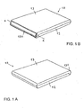
- FIGS. 1A and 1B show the front and the back of the box with its cover 13 folded over the top of the tray.
- the lid is fixed on the plate by fixing means which define a pivot axis XX so that the lid 13 can be raised in a position substantially perpendicular to the plate 12 and so that it can be folded over the top of said tray .
- a first portion of the collapsible structure 14 is attached to the upper face of the tray 12 and a second portion of the structure 14 is attached to the inner face of the lid 13.
- the collapsible structure is attached to the tray 12 detachably by tabs 16 formed on a flange 15 of the tray and is releasably attached to the cover 13 by lugs 18 formed on a flange 17 of the lid, which flange extends substantially perpendicular to the plane of the lid. lid.
- the cover 13 may also have a rear flange 131 which rests on or against a portion of the rear side of the tray 12 when the lid is in the raised position.
- This rim 131 thus provides a stabilization function for the lid in the raised position, in addition to the locking function provided by the locking elements 124 and 134.
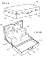
- FIGS. 6A and 6B show the box with raised lid, respectively seen from before and seen from behind.
- the stability of the lid in its raised position is completed by the support of the rear edge 131 of the lid against the rear side of the plate 12.
- the decoration 14 is attached to the upper surface of the plate 12 by the tabs 16 and to the inner face of the cover 13 by the legs 18 as in the embodiment described above.
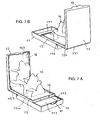
- FIGS 7A and 7B represent the box, seen from front and rear, when the plate 12 has been brought into a retracted position by sliding relative to the basket 11. In this position, the plate 12 releases the top of the basket 11 and makes it accessible the inner compartment thereof, said inner compartment can serve as storage space 111 for various objects.
- two opposite side walls 112 of the basket 11 have longitudinal ribs 113 which cooperate with grooves 123 formed along two opposite sides of the plate 12. Stop means 114 and 124 formed at the rear end of the ribs 113 and 123 grooves cooperate with each other so as to stop the travel of the plate 12 when it is in its advanced position, in which position it closes the top of the basket 11 .
- FIGS 8A and 8B illustrate an alternative embodiment of the embodiment of the invention described above.
- the lid 13 is fixed on a large side of the plate 12. This arrangement aside, this embodiment has all the features and all the advantages of the embodiment. represented at figures 5 , 6 and 7 .
Abstract
Description
La présente invention concerne un coffret doté d'une structure pliable et dépliable dans l'espace.The present invention relates to a cabinet with a foldable structure and unfoldable in space.
Par
Un premier objectif de la présente invention est de réaliser un coffret nouveau qui peut être moulé avec les moyens de fixation du couvercle relevable.A first object of the present invention is to provide a new cabinet that can be molded with the fastening means of the lift lid.
Un deuxième objectif est de réaliser un coffret nouveau qui combine et intègre un contenant pour objets divers avec une structure de décor dépliable dans l'espace.A second objective is to create a new box that combines and integrates a container for various objects with a foldable decor structure in the space.
Le coffret avec structure déployable suivant l'invention se distingue par les caractéristiques définies dans les revendications. Dans ce coffret, le couvercle est fixé sur le dessus d'un plateau par simple emboîtement et le plateau est monté sur une corbeille de manière à pouvoir coulisser par rapport à celle-ci. Le relèvement du couvercle par rapport au plateau déploie le décor qui y est attaché et en amenant le plateau dans une position reculée par coulissement par rapport à la corbeille sur le dessus de laquelle il est fixé, le plateau entraîne le décor tout en dégageant le dessus de la corbeille et en rendant accessible un compartiment intérieur servant d'espace de rangement pour des objets divers.The box with deployable structure according to the invention is distinguished by the features defined in the claims. In this box, the lid is fixed on the top of a tray by simple interlocking and the tray is mounted on a basket so as to slide relative thereto. The lifting of the lid relative to the tray deploys the decor attached thereto and bringing the tray in a retracted position by sliding relative to the basket on top of which it is fixed, the tray causes the decor while clearing the top the basket and making accessible an interior compartment for storage space for various objects.
Quelques exemples de mode de réalisation de l'invention sont décrits en détails dans ce qui suit à l'aide des dessins joints.Some exemplary embodiments of the invention are described in detail in the following with the aid of the accompanying drawings.
-
Les
figures 1A et 1B représentent des vues en perspective avant et arrière d'un coffret sans corbeille.TheFigures 1A and 1B represent front and back perspective views of a box without a basket. -
Les
figures 2A et 2B montrent des vues avant et arrière du coffret de lafigure 1 avec couvercle en position relevée;TheFigures 2A and 2B show front and back views of the cabinet of thefigure 1 with lid in raised position; -
La
figure 3 est une vue éclatée du coffret montré à lafigure 2 ;Thefigure 3 is an exploded view of the box shown atfigure 2 ; -
Les
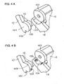
figures 4A et 4B illustrent deux exemples de mode de réalisation pour la fixation du couvercle;TheFigures 4A and 4B illustrate two exemplary embodiments for fixing the lid; -
Les
figures 5A et 5B représentent des vues en perspective avant et arrière d'un coffret suivant un mode de réalisation de l'invention ;TheFigures 5A and 5B represent front and rear perspective views of a box according to one embodiment of the invention; -
Les
figures 6A et 6B montrent des vues avant et arrière du coffret de lafigure 5 avec couvercle relevé;TheFigures 6A and 6B show front and back views of the cabinet of thefigure 5 with raised lid; -
Les
figures 7A et 7B montrent des vues avant et arrière du coffret de lafigure 5 avec couvercle relevé et corbeille ouverte ;TheFigures 7A and 7B show front and back views of the cabinet of thefigure 5 with raised lid and open basket; -
Les
figures 8A et 8B illustrent une variante du coffret représenté auxfigures 5 ,6 et7 .TheFigures 8A and 8B illustrate a variant of the box shown infigures 5 ,6 and7 .
Dans ces dessins, les mêmes signes de référence désignent des éléments identiques, similaires ou équivalents.In these drawings, the same reference signs designate identical, similar or equivalent elements.
Se reportant aux
Les
Les
Une première partie de la structure repliable 14 est attachée à la face supérieure du plateau 12 et une deuxième partie de la structure 14 est attachée à la face intérieure du couvercle 13. Dans le mode de réalisation illustré, la structure repliable est attachée au plateau 12, de manière détachable, par des pattes 16 formées sur un rebord 15 du plateau et elle est attachée au couvercle 13, de manière détachable, par des pattes 18 formées sur un rebord 17 du couvercle, lequel rebord s'étend pratiquement perpendiculairement au plan du couvercle. Lorsqu'une structure repliable 14 se trouve ainsi attachée au plateau 12 et au couvercle 13, elle se replie automatiquement sur elle-même lorsque le couvercle 13 est rabattu sur le dessus du plateau 12, repliant automatiquement les éléments composant le décor, qui s'étaient déployés dans l'espace, et elle se redéploie automatiquement dans l'espace lorsque le couvercle 13 est amené dans sa position relevée.A first portion of the
La structure dépliable et repliable peut être réalisée de diverses manières et avec des présentations qui peuvent varier. Elle peut être constituée d'une structure dépliable quelconque. Avantageusement, la structure dépliable/repliable attachée dans le coffret consiste en un support pliable en formant une première partie 14a et une seconde partie 14b, ledit support étant percé de plusieurs fentes délimitant latéralement des éléments 14c qui présentent des pliures s'étendant entre les fentes précitées et disposées de manière appropriée pour créer un décor choisi. Les éléments 14c de la structure dépliable peuvent être déployés dans l'espace en formant un ou plusieurs plans parallèles à l'une ou l'autre desdites parties 14a et 14b du support. Chaque élément dépliable dans l'espace peut avoir de nombreuses configurations et être orné librement pour réaliser un décor voulu quelconque.The foldable and collapsible structure can be realized in various ways and with presentations that may vary. It may consist of any unfoldable structure. Advantageously, the foldable / foldable structure attached in the box consists of a foldable support forming a
La
La
La
Dans ce mode de réalisation, le couvercle 13 peut également présenter un rebord arrière 131 qui vient reposer sur ou contre une partie du côté arrière du plateau 12 lorsque le couvercle se trouve en position relevée. Ce rebord 131 assure ainsi une fonction de stabilisation pour le couvercle en position relevée, complémentairement à la fonction de verrouillage assurée par les éléments de verrouillage 124 et 134.In this embodiment, the
Les
Dans l'exemple illustré, le couvercle 13 est muni d'une languette de fermeture 19 destinée à coopérer avec un logement 21 ménagé sur le rebord correspondant du plateau 12 et de la corbeille 11. Lorsque le couvercle se trouve rabattu sur le dessus du plateau 12, la languette 19 maintient le couvercle 13 en position rabattue et la corbeille fermée. Avantageusement, des aspérités sont formées dans le logement afin de parfaire l'adhérence de la languette de fermeture 19. Des aspérités servant à cet usage sont représentées à titre d'exemple sur les
Les
Les
La languette de fermeture 19 qui s'étend de manière à attacher le couvercle rabattu 13 à la paroi de la corbeille 11 empêche le glissement du plateau 12 et l'ouverture de la corbeille 11 tant que le couvercle 13 se trouve rabattu sur le dessus du plateau 12. De cette manière, l'accès à l'espace intérieur de la corbeille 11 n'est possible que lorsque l'utilisateur a relevé le couvercle 13 qui, ce faisant, déploie automatiquement le décor dépliable comme décrit plus haut.The
Les
Claims (10)
- Case for accommodating an unfoldable/foldable structure, said case comprising a plate (12), a lid (13) attached to said plate so as to be able to pivot between a retracted position on the plate and a raised position that is virtually perpendicular to the plate (12), the latter comprising two first attachment elements (122) and the lid (13) comprising two second attachment elements (132), each attachment element of the lid working by interlocking with an attachment element of the plate so as to define a pivot axis (X-X) for the lid, and means that are arranged to assure a stable position to the lid (13) when it is in its raised position, characterised in that the plate (12) is attached to the top of a basket (11) so as to be able to slide relative to the latter.
- Case according to claim 1, characterised in that the plate (12) has first rectilinear elements (123) suitable for working with second rectilinear elements (113) that are provided on the lateral wall of the basket (11) so as to allow the first above-mentioned rectilinear elements to slide longitudinally relative to the second above-mentioned rectilinear elements.
- Case according to any of the preceding claims, characterised in that the lid (13) has a means (19) that extends so as to connect the lid (13) to the plate (12) and to the lateral wall of the basket (11) and to prevent the plate (12) from sliding when the lid (13) is retracted on the plate (12).
- Case according to any of the preceding claims, characterised in that each first attachment element (122) is profiled in an arch (123), and each second attachment element (132) is profiled in an arch (123) that is working with the profile (123) of one of said first attachment elements (122) of the plate (12).
- Case according to any of the preceding claims, characterised in that the means for assuring a stable raised position to the lid (13) comprise locking elements (124, 134) that are combined with the attachment means (122, 132) of the lid (13).
- Case according to any of the preceding claims, characterised in that the attachment means of the lid (13) comprise locking means (124, 125, 134) that are arranged for locking the lid in several positions relative to the plate (12).
- Case according to any of the preceding claims, characterised in that the lid (13) has on its rear side an outside flange (131) that rests against the rear flange (15) of the plate (12) when the lid is in a raised position that is virtually perpendicular to the plate.
- Case according to any of the preceding claims, characterised in that the plate (12) has attachment brackets (16) for holding a first portion (14a) of a foldable structure and in that the lid (13) has attachment brackets (18) for holding a second portion (14b) of the foldable structure.
- Case according to any of the preceding claims, characterised in that it accommodates an unfoldable/foldable structure (14) structure that consists of a foldable sheet having a first portion (14a) that is attached to the plate (12) and a second portion (14b) that is attached to the lid (13).
- Case according to claim 9, characterised in that the foldable sheet is pierced by several slots that laterally delimit elements (14c) that have folds that extend between the above-mentioned slots and that can be deployed in the space by forming at least one plane that is parallel to at least one of the first and second portions of the foldable sheet.
Priority Applications (1)
| Application Number | Priority Date | Filing Date | Title |
|---|---|---|---|
| PL06707623T PL1893048T3 (en) | 2005-04-22 | 2006-03-15 | Case with deployable structure |
Applications Claiming Priority (2)
| Application Number | Priority Date | Filing Date | Title |
|---|---|---|---|
| BE2005/0207A BE1017418A3 (en) | 2005-04-22 | 2005-04-22 | BOX WITH DEPLOYABLE STRUCTURE. |
| PCT/EP2006/002582 WO2006111232A1 (en) | 2005-04-22 | 2006-03-15 | Case with deployable structure |
Publications (2)
| Publication Number | Publication Date |
|---|---|
| EP1893048A1 EP1893048A1 (en) | 2008-03-05 |
| EP1893048B1 true EP1893048B1 (en) | 2009-08-19 |
Family
ID=36555691
Family Applications (1)
| Application Number | Title | Priority Date | Filing Date |
|---|---|---|---|
| EP06707623A Not-in-force EP1893048B1 (en) | 2005-04-22 | 2006-03-15 | Case with deployable structure |
Country Status (11)
| Country | Link |
|---|---|
| US (1) | US20100012672A1 (en) |
| EP (1) | EP1893048B1 (en) |
| AT (1) | ATE439775T1 (en) |
| BE (1) | BE1017418A3 (en) |
| CA (1) | CA2606294C (en) |
| DE (1) | DE602006008614D1 (en) |
| DK (1) | DK1893048T3 (en) |
| ES (1) | ES2331966T3 (en) |
| PL (1) | PL1893048T3 (en) |
| PT (1) | PT1893048E (en) |
| WO (1) | WO2006111232A1 (en) |
Cited By (1)
| Publication number | Priority date | Publication date | Assignee | Title |
|---|---|---|---|---|
| US9138655B2 (en) | 2013-12-09 | 2015-09-22 | Mattel, Inc. | Expandable playset |
Families Citing this family (16)
| Publication number | Priority date | Publication date | Assignee | Title |
|---|---|---|---|---|
| FR2931344B1 (en) * | 2008-05-21 | 2010-08-20 | Oreal | PACKAGE FOR CONDITIONING A PRODUCT, IN PARTICULAR A COSMETIC PRODUCT |
| US8474619B1 (en) * | 2010-11-29 | 2013-07-02 | Craig R. Chrisman | Unitary gift card box |
| EP2471406B1 (en) | 2010-12-28 | 2019-05-01 | Albéa Services | Casing for a cosmetic article |
| BE1020870A3 (en) * | 2012-08-31 | 2014-06-03 | David Piron | BOX FOR PACKAGING AND / OR DISTRIBUTION OF PRODUCTS. |
| BE1020871A3 (en) | 2012-08-31 | 2014-06-03 | David Piron | BOX FOR PACKAGING AND / OR DISTRIBUTION OF PRODUCTS. |
| USD755641S1 (en) | 2014-08-15 | 2016-05-10 | Sugarfina, LLC | Packaging |
| USD731323S1 (en) | 2014-08-15 | 2015-06-09 | Sugarfina, LLC | Packaging |
| JP1623581S (en) | 2017-06-30 | 2019-02-04 | ||
| USD845788S1 (en) | 2017-06-30 | 2019-04-16 | Sugarfina Inc. | Packaging |
| USD823696S1 (en) | 2017-06-30 | 2018-07-24 | Sugarfina, Inc. | Packaging |
| USD844454S1 (en) | 2017-06-30 | 2019-04-02 | Sugarfina Inc. | Packaging |
| USD823134S1 (en) | 2017-06-30 | 2018-07-17 | Sugarfina, Inc. | Packaging |
| USD845787S1 (en) | 2017-06-30 | 2019-04-16 | Sugarfina Inc. | Packaging |
| US10053274B1 (en) | 2017-09-18 | 2018-08-21 | Sugarfina, Inc. | Packaging and display apparatus |
| USD829569S1 (en) | 2017-09-18 | 2018-10-02 | Sugarfina, Inc. | Packaging |
| FR3127379B1 (en) * | 2021-09-27 | 2023-08-25 | Albea Services | Receptacle for cosmetic product designed in plastic monomaterial |
Family Cites Families (11)
| Publication number | Priority date | Publication date | Assignee | Title |
|---|---|---|---|---|
| US2735541A (en) * | 1956-02-21 | mosler | ||
| US2511211A (en) * | 1946-04-26 | 1950-06-13 | Klein Benjamin | Novelty box |
| DE1532860A1 (en) * | 1967-06-20 | 1970-03-12 | Praezisola Grosshans & Co | Plastic hinge |
| US3695481A (en) * | 1970-10-08 | 1972-10-03 | Clark Mfg Co J L | Hinged plastic closure for sheet metal cans |
| FR2466970A1 (en) * | 1979-10-08 | 1981-04-17 | Embadac | BOX-DISPLAY |
| DE9111415U1 (en) * | 1991-09-13 | 1993-01-28 | Ramoser, Christian, 8912 Kaufering, De | |
| WO1995033392A1 (en) * | 1994-06-08 | 1995-12-14 | The Procter & Gamble Company | Hinged package having an adjustable cover |
| US5613612A (en) * | 1995-03-15 | 1997-03-25 | Davault; Elaine J. | Combination 3-D pop-up display and CD holder |
| BE1009323A6 (en) * | 1995-05-18 | 1997-02-04 | Piron David | Decor fold structure. |
| AU2003228987A1 (en) * | 2002-05-09 | 2003-11-11 | Rubbermaid Incorporated | Multifunction container hinge |
| US20060191948A1 (en) * | 2005-01-25 | 2006-08-31 | Seaquist Closures Foreign, Inc. | Closure with lid having an opening resistance |
-
2005
- 2005-04-22 BE BE2005/0207A patent/BE1017418A3/en not_active IP Right Cessation
-
2006
- 2006-03-15 EP EP06707623A patent/EP1893048B1/en not_active Not-in-force
- 2006-03-15 US US11/912,232 patent/US20100012672A1/en not_active Abandoned
- 2006-03-15 ES ES06707623T patent/ES2331966T3/en active Active
- 2006-03-15 AT AT06707623T patent/ATE439775T1/en active
- 2006-03-15 WO PCT/EP2006/002582 patent/WO2006111232A1/en active Application Filing
- 2006-03-15 DE DE602006008614T patent/DE602006008614D1/en active Active
- 2006-03-15 CA CA2606294A patent/CA2606294C/en not_active Expired - Fee Related
- 2006-03-15 PT PT06707623T patent/PT1893048E/en unknown
- 2006-03-15 PL PL06707623T patent/PL1893048T3/en unknown
- 2006-03-15 DK DK06707623T patent/DK1893048T3/en active
Cited By (1)
| Publication number | Priority date | Publication date | Assignee | Title |
|---|---|---|---|---|
| US9138655B2 (en) | 2013-12-09 | 2015-09-22 | Mattel, Inc. | Expandable playset |
Also Published As
| Publication number | Publication date |
|---|---|
| ES2331966T3 (en) | 2010-01-21 |
| DE602006008614D1 (en) | 2009-10-01 |
| US20100012672A1 (en) | 2010-01-21 |
| WO2006111232A1 (en) | 2006-10-26 |
| CA2606294A1 (en) | 2006-10-26 |
| ATE439775T1 (en) | 2009-09-15 |
| PT1893048E (en) | 2009-11-17 |
| DK1893048T3 (en) | 2009-12-14 |
| CA2606294C (en) | 2011-11-22 |
| PL1893048T3 (en) | 2010-01-29 |
| BE1017418A3 (en) | 2008-09-02 |
| EP1893048A1 (en) | 2008-03-05 |
Similar Documents
| Publication | Publication Date | Title |
|---|---|---|
| EP1893048B1 (en) | Case with deployable structure | |
| CA2374692C (en) | Make-up type housing comprising an articulated lid | |
| EP1034720B1 (en) | Make-up assembly with at least two products of different types | |
| FR2785510A1 (en) | Cosmetics compact has case to receive rechargeable container with hinged lid | |
| BE1009323A6 (en) | Decor fold structure. | |
| EP2339938B1 (en) | Case for cosmetic or body hygiene product having a retractable hinge | |
| EP1500347A1 (en) | Cosmetic case with ejectable drawer | |
| EP0574284A1 (en) | Case provided with closure having no moving parts | |
| FR2593040A3 (en) | Visiting-card-holder structure equipped with means for extracting individual cards | |
| FR2992264A1 (en) | Closure device for closing e.g. compartment provided below seat of car, has front cover provided with two rectangular openings that horizontally extend according to direction, and two flaps swivelingly adapted to seal or close openings | |
| WO1998032632A1 (en) | Device comprising an attache case forming a level top | |
| FR2919836A1 (en) | Object storage module for central seat of rear seat bank in motor vehicle, has walls with surfaces articulated around axle such that surfaces are folded relative to each other, where each surface is articulated at end around another axle | |
| FR3104923A1 (en) | Cosmetic product case comprising a cover, a base and a hinge | |
| WO1994020309A1 (en) | Adaptable shopping list support | |
| EP3568037B1 (en) | Folding piece of luggage | |
| FR3054416A1 (en) | PACKAGING DEVICE FOR COSMETIC PRODUCT | |
| FR2919835A1 (en) | Object storage module for central seat of rear seat bank in motor vehicle, has retractable walls with faces articulated around axle so that faces are folded relative to each other, where each face is articulated at end around another axle | |
| FR3106041A1 (en) | Toiletry case | |
| EP1736362B1 (en) | Collapsible mechanism for partitioning the load compartment of a motor vehicle and corresponding motor vehicle | |
| WO2003079843A2 (en) | Bag which can be converted into a work station | |
| EP1524155A1 (en) | Storage assembly for vehicle interior | |
| FR2788203A1 (en) | Unit for sink or basin, comprises a collapsible structure that can be stowed away | |
| WO2017202555A1 (en) | Case for cosmetic product, notably makeup | |
| EP1479311A1 (en) | Device for storing and applying a cosmetic product | |
| FR2870691A1 (en) | Hand luggage for e.g. cosmetics, has pivoting wall connected to body via hinge to permit translatory movement of wall between closed position and intermediate position, where wall is disengaged towards exterior of body when wall is opened |
Legal Events
| Date | Code | Title | Description |
|---|---|---|---|
| PUAI | Public reference made under article 153(3) epc to a published international application that has entered the european phase |
Free format text: ORIGINAL CODE: 0009012 |
|
| 17P | Request for examination filed |
Effective date: 20071112 |
|
| AK | Designated contracting states |
Kind code of ref document: A1 Designated state(s): AT BE BG CH CY CZ DE DK EE ES FI FR GB GR HU IE IS IT LI LT LU LV MC NL PL PT RO SE SI SK TR |
|
| 17Q | First examination report despatched |
Effective date: 20080424 |
|
| DAX | Request for extension of the european patent (deleted) | ||
| GRAP | Despatch of communication of intention to grant a patent |
Free format text: ORIGINAL CODE: EPIDOSNIGR1 |
|
| GRAS | Grant fee paid |
Free format text: ORIGINAL CODE: EPIDOSNIGR3 |
|
| GRAA | (expected) grant |
Free format text: ORIGINAL CODE: 0009210 |
|
| AK | Designated contracting states |
Kind code of ref document: B1 Designated state(s): AT BE BG CH CY CZ DE DK EE ES FI FR GB GR HU IE IS IT LI LT LU LV MC NL PL PT RO SE SI SK TR |
|
| REG | Reference to a national code |
Ref country code: GB Ref legal event code: FG4D Free format text: NOT ENGLISH |
|
| RAP2 | Party data changed (patent owner data changed or rights of a patent transferred) |
Owner name: PIRON, DAVID |
|
| RIN2 | Information on inventor provided after grant (corrected) |
Inventor name: PIRON, DAVID |
|
| REG | Reference to a national code |
Ref country code: CH Ref legal event code: EP |
|
| REG | Reference to a national code |
Ref country code: IE Ref legal event code: FG4D |
|
| REF | Corresponds to: |
Ref document number: 602006008614 Country of ref document: DE Date of ref document: 20091001 Kind code of ref document: P |
|
| NLT2 | Nl: modifications (of names), taken from the european patent patent bulletin |
Owner name: PIRON, DAVID Effective date: 20090826 |
|
| REG | Reference to a national code |
Ref country code: PT Ref legal event code: SC4A Free format text: AVAILABILITY OF NATIONAL TRANSLATION Effective date: 20091110 |
|
| REG | Reference to a national code |
Ref country code: SE Ref legal event code: TRGR |
|
| REG | Reference to a national code |
Ref country code: DK Ref legal event code: T3 |
|
| REG | Reference to a national code |
Ref country code: GR Ref legal event code: EP Ref document number: 20090402802 Country of ref document: GR |
|
| REG | Reference to a national code |
Ref country code: ES Ref legal event code: FG2A Ref document number: 2331966 Country of ref document: ES Kind code of ref document: T3 |
|
| LTIE | Lt: invalidation of european patent or patent extension |
Effective date: 20090819 |
|
| PG25 | Lapsed in a contracting state [announced via postgrant information from national office to epo] |
Ref country code: IS Free format text: LAPSE BECAUSE OF FAILURE TO SUBMIT A TRANSLATION OF THE DESCRIPTION OR TO PAY THE FEE WITHIN THE PRESCRIBED TIME-LIMIT Effective date: 20091219 Ref country code: LT Free format text: LAPSE BECAUSE OF FAILURE TO SUBMIT A TRANSLATION OF THE DESCRIPTION OR TO PAY THE FEE WITHIN THE PRESCRIBED TIME-LIMIT Effective date: 20090819 |
|
| REG | Reference to a national code |
Ref country code: PL Ref legal event code: T3 |
|
| PG25 | Lapsed in a contracting state [announced via postgrant information from national office to epo] |
Ref country code: SI Free format text: LAPSE BECAUSE OF FAILURE TO SUBMIT A TRANSLATION OF THE DESCRIPTION OR TO PAY THE FEE WITHIN THE PRESCRIBED TIME-LIMIT Effective date: 20090819 Ref country code: LV Free format text: LAPSE BECAUSE OF FAILURE TO SUBMIT A TRANSLATION OF THE DESCRIPTION OR TO PAY THE FEE WITHIN THE PRESCRIBED TIME-LIMIT Effective date: 20090819 |
|
| REG | Reference to a national code |
Ref country code: IE Ref legal event code: FD4D |
|
| REG | Reference to a national code |
Ref country code: HU Ref legal event code: AG4A Ref document number: E006921 Country of ref document: HU |
|
| PG25 | Lapsed in a contracting state [announced via postgrant information from national office to epo] |
Ref country code: BG Free format text: LAPSE BECAUSE OF FAILURE TO SUBMIT A TRANSLATION OF THE DESCRIPTION OR TO PAY THE FEE WITHIN THE PRESCRIBED TIME-LIMIT Effective date: 20091119 Ref country code: CY Free format text: LAPSE BECAUSE OF FAILURE TO SUBMIT A TRANSLATION OF THE DESCRIPTION OR TO PAY THE FEE WITHIN THE PRESCRIBED TIME-LIMIT Effective date: 20090819 |
|
| PG25 | Lapsed in a contracting state [announced via postgrant information from national office to epo] |
Ref country code: IE Free format text: LAPSE BECAUSE OF FAILURE TO SUBMIT A TRANSLATION OF THE DESCRIPTION OR TO PAY THE FEE WITHIN THE PRESCRIBED TIME-LIMIT Effective date: 20090819 Ref country code: RO Free format text: LAPSE BECAUSE OF FAILURE TO SUBMIT A TRANSLATION OF THE DESCRIPTION OR TO PAY THE FEE WITHIN THE PRESCRIBED TIME-LIMIT Effective date: 20090819 Ref country code: CZ Free format text: LAPSE BECAUSE OF FAILURE TO SUBMIT A TRANSLATION OF THE DESCRIPTION OR TO PAY THE FEE WITHIN THE PRESCRIBED TIME-LIMIT Effective date: 20090819 Ref country code: EE Free format text: LAPSE BECAUSE OF FAILURE TO SUBMIT A TRANSLATION OF THE DESCRIPTION OR TO PAY THE FEE WITHIN THE PRESCRIBED TIME-LIMIT Effective date: 20090819 |
|
| PG25 | Lapsed in a contracting state [announced via postgrant information from national office to epo] |
Ref country code: SK Free format text: LAPSE BECAUSE OF FAILURE TO SUBMIT A TRANSLATION OF THE DESCRIPTION OR TO PAY THE FEE WITHIN THE PRESCRIBED TIME-LIMIT Effective date: 20090819 |
|
| PLBE | No opposition filed within time limit |
Free format text: ORIGINAL CODE: 0009261 |
|
| STAA | Information on the status of an ep patent application or granted ep patent |
Free format text: STATUS: NO OPPOSITION FILED WITHIN TIME LIMIT |
|
| 26N | No opposition filed |
Effective date: 20100520 |
|
| PG25 | Lapsed in a contracting state [announced via postgrant information from national office to epo] |
Ref country code: MC Free format text: LAPSE BECAUSE OF NON-PAYMENT OF DUE FEES Effective date: 20100331 |
|
| PG25 | Lapsed in a contracting state [announced via postgrant information from national office to epo] |
Ref country code: LU Free format text: LAPSE BECAUSE OF NON-PAYMENT OF DUE FEES Effective date: 20100315 |
|
| PGFP | Annual fee paid to national office [announced via postgrant information from national office to epo] |
Ref country code: CH Payment date: 20130326 Year of fee payment: 8 Ref country code: FI Payment date: 20130327 Year of fee payment: 8 Ref country code: SE Payment date: 20130326 Year of fee payment: 8 Ref country code: DK Payment date: 20130321 Year of fee payment: 8 Ref country code: HU Payment date: 20130311 Year of fee payment: 8 |
|
| PGFP | Annual fee paid to national office [announced via postgrant information from national office to epo] |
Ref country code: PL Payment date: 20130219 Year of fee payment: 8 Ref country code: GR Payment date: 20130328 Year of fee payment: 8 |
|
| PGFP | Annual fee paid to national office [announced via postgrant information from national office to epo] |
Ref country code: PT Payment date: 20130228 Year of fee payment: 8 Ref country code: AT Payment date: 20130327 Year of fee payment: 8 |
|
| PGFP | Annual fee paid to national office [announced via postgrant information from national office to epo] |
Ref country code: BE Payment date: 20130321 Year of fee payment: 8 |
|
| PGFP | Annual fee paid to national office [announced via postgrant information from national office to epo] |
Ref country code: NL Payment date: 20130321 Year of fee payment: 8 |
|
| REG | Reference to a national code |
Ref country code: PT Ref legal event code: MM4A Free format text: LAPSE DUE TO NON-PAYMENT OF FEES Effective date: 20140915 |
|
| REG | Reference to a national code |
Ref country code: DK Ref legal event code: EBP Effective date: 20140331 |
|
| REG | Reference to a national code |
Ref country code: NL Ref legal event code: V1 Effective date: 20141001 |
|
| PG25 | Lapsed in a contracting state [announced via postgrant information from national office to epo] |
Ref country code: FI Free format text: LAPSE BECAUSE OF NON-PAYMENT OF DUE FEES Effective date: 20140315 |
|
| REG | Reference to a national code |
Ref country code: CH Ref legal event code: PL |
|
| REG | Reference to a national code |
Ref country code: SE Ref legal event code: EUG |
|
| REG | Reference to a national code |
Ref country code: AT Ref legal event code: MM01 Ref document number: 439775 Country of ref document: AT Kind code of ref document: T Effective date: 20140315 |
|
| REG | Reference to a national code |
Ref country code: GR Ref legal event code: ML Ref document number: 20090402802 Country of ref document: GR Effective date: 20141002 |
|
| PG25 | Lapsed in a contracting state [announced via postgrant information from national office to epo] |
Ref country code: SE Free format text: LAPSE BECAUSE OF NON-PAYMENT OF DUE FEES Effective date: 20140316 |
|
| PG25 | Lapsed in a contracting state [announced via postgrant information from national office to epo] |
Ref country code: PT Free format text: LAPSE BECAUSE OF NON-PAYMENT OF DUE FEES Effective date: 20140915 |
|
| PG25 | Lapsed in a contracting state [announced via postgrant information from national office to epo] |
Ref country code: LI Free format text: LAPSE BECAUSE OF NON-PAYMENT OF DUE FEES Effective date: 20140331 Ref country code: CH Free format text: LAPSE BECAUSE OF NON-PAYMENT OF DUE FEES Effective date: 20140331 Ref country code: GR Free format text: LAPSE BECAUSE OF NON-PAYMENT OF DUE FEES Effective date: 20141002 |
|
| PG25 | Lapsed in a contracting state [announced via postgrant information from national office to epo] |
Ref country code: NL Free format text: LAPSE BECAUSE OF NON-PAYMENT OF DUE FEES Effective date: 20141001 Ref country code: AT Free format text: LAPSE BECAUSE OF NON-PAYMENT OF DUE FEES Effective date: 20140315 Ref country code: HU Free format text: LAPSE BECAUSE OF NON-PAYMENT OF DUE FEES Effective date: 20140316 |
|
| REG | Reference to a national code |
Ref country code: FR Ref legal event code: PLFP Year of fee payment: 10 |
|
| PG25 | Lapsed in a contracting state [announced via postgrant information from national office to epo] |
Ref country code: DK Free format text: LAPSE BECAUSE OF NON-PAYMENT OF DUE FEES Effective date: 20140331 |
|
| PGFP | Annual fee paid to national office [announced via postgrant information from national office to epo] |
Ref country code: DE Payment date: 20150320 Year of fee payment: 10 Ref country code: IT Payment date: 20150323 Year of fee payment: 10 Ref country code: ES Payment date: 20150326 Year of fee payment: 10 |
|
| PG25 | Lapsed in a contracting state [announced via postgrant information from national office to epo] |
Ref country code: PL Free format text: LAPSE BECAUSE OF NON-PAYMENT OF DUE FEES Effective date: 20140315 |
|
| PGFP | Annual fee paid to national office [announced via postgrant information from national office to epo] |
Ref country code: GB Payment date: 20150319 Year of fee payment: 10 Ref country code: TR Payment date: 20150319 Year of fee payment: 10 Ref country code: FR Payment date: 20150319 Year of fee payment: 10 |
|
| REG | Reference to a national code |
Ref country code: PL Ref legal event code: LAPE |
|
| REG | Reference to a national code |
Ref country code: DE Ref legal event code: R119 Ref document number: 602006008614 Country of ref document: DE |
|
| GBPC | Gb: european patent ceased through non-payment of renewal fee |
Effective date: 20160315 |
|
| REG | Reference to a national code |
Ref country code: FR Ref legal event code: ST Effective date: 20161130 |
|
| PG25 | Lapsed in a contracting state [announced via postgrant information from national office to epo] |
Ref country code: GB Free format text: LAPSE BECAUSE OF NON-PAYMENT OF DUE FEES Effective date: 20160315 Ref country code: FR Free format text: LAPSE BECAUSE OF NON-PAYMENT OF DUE FEES Effective date: 20160331 Ref country code: DE Free format text: LAPSE BECAUSE OF NON-PAYMENT OF DUE FEES Effective date: 20161001 |
|
| PG25 | Lapsed in a contracting state [announced via postgrant information from national office to epo] |
Ref country code: IT Free format text: LAPSE BECAUSE OF NON-PAYMENT OF DUE FEES Effective date: 20160315 |
|
| PG25 | Lapsed in a contracting state [announced via postgrant information from national office to epo] |
Ref country code: BE Free format text: LAPSE BECAUSE OF NON-PAYMENT OF DUE FEES Effective date: 20140331 |
|
| PG25 | Lapsed in a contracting state [announced via postgrant information from national office to epo] |
Ref country code: ES Free format text: LAPSE BECAUSE OF NON-PAYMENT OF DUE FEES Effective date: 20160316 |
|
| REG | Reference to a national code |
Ref country code: ES Ref legal event code: FD2A Effective date: 20181207 |
|
| PG25 | Lapsed in a contracting state [announced via postgrant information from national office to epo] |
Ref country code: TR Free format text: LAPSE BECAUSE OF NON-PAYMENT OF DUE FEES Effective date: 20160315 |