EP1892484A1 - Air cooling/heating device - Google Patents
Air cooling/heating device Download PDFInfo
- Publication number
- EP1892484A1 EP1892484A1 EP06254389A EP06254389A EP1892484A1 EP 1892484 A1 EP1892484 A1 EP 1892484A1 EP 06254389 A EP06254389 A EP 06254389A EP 06254389 A EP06254389 A EP 06254389A EP 1892484 A1 EP1892484 A1 EP 1892484A1
- Authority
- EP
- European Patent Office
- Prior art keywords
- unit
- compartment
- heating device
- air cooling
- thermal energy
- Prior art date
- Legal status (The legal status is an assumption and is not a legal conclusion. Google has not performed a legal analysis and makes no representation as to the accuracy of the status listed.)
- Withdrawn
Links
- 238000010438 heat treatment Methods 0.000 title claims abstract description 27
- 238000001816 cooling Methods 0.000 title claims abstract description 26
- 239000004065 semiconductor Substances 0.000 claims abstract description 16
- 230000002528 anti-freeze Effects 0.000 claims abstract description 15
- 239000007788 liquid Substances 0.000 claims abstract description 15
- 238000005192 partition Methods 0.000 claims description 10
- LYCAIKOWRPUZTN-UHFFFAOYSA-N Ethylene glycol Chemical compound OCCO LYCAIKOWRPUZTN-UHFFFAOYSA-N 0.000 description 3
- 230000005611 electricity Effects 0.000 description 3
- 238000004519 manufacturing process Methods 0.000 description 2
- 230000003247 decreasing effect Effects 0.000 description 1
- 238000010586 diagram Methods 0.000 description 1
- 238000012544 monitoring process Methods 0.000 description 1
- XLYOFNOQVPJJNP-UHFFFAOYSA-N water Substances O XLYOFNOQVPJJNP-UHFFFAOYSA-N 0.000 description 1
Images

Classifications
-
- F—MECHANICAL ENGINEERING; LIGHTING; HEATING; WEAPONS; BLASTING
- F24—HEATING; RANGES; VENTILATING
- F24F—AIR-CONDITIONING; AIR-HUMIDIFICATION; VENTILATION; USE OF AIR CURRENTS FOR SCREENING
- F24F5/00—Air-conditioning systems or apparatus not covered by F24F1/00 or F24F3/00, e.g. using solar heat or combined with household units such as an oven or water heater
- F24F5/0042—Air-conditioning systems or apparatus not covered by F24F1/00 or F24F3/00, e.g. using solar heat or combined with household units such as an oven or water heater characterised by the application of thermo-electric units or the Peltier effect
-
- F—MECHANICAL ENGINEERING; LIGHTING; HEATING; WEAPONS; BLASTING
- F24—HEATING; RANGES; VENTILATING
- F24F—AIR-CONDITIONING; AIR-HUMIDIFICATION; VENTILATION; USE OF AIR CURRENTS FOR SCREENING
- F24F1/00—Room units for air-conditioning, e.g. separate or self-contained units or units receiving primary air from a central station
- F24F1/02—Self-contained room units for air-conditioning, i.e. with all apparatus for treatment installed in a common casing
- F24F1/022—Self-contained room units for air-conditioning, i.e. with all apparatus for treatment installed in a common casing comprising a compressor cycle
-
- F—MECHANICAL ENGINEERING; LIGHTING; HEATING; WEAPONS; BLASTING
- F24—HEATING; RANGES; VENTILATING
- F24F—AIR-CONDITIONING; AIR-HUMIDIFICATION; VENTILATION; USE OF AIR CURRENTS FOR SCREENING
- F24F5/00—Air-conditioning systems or apparatus not covered by F24F1/00 or F24F3/00, e.g. using solar heat or combined with household units such as an oven or water heater
- F24F5/0007—Air-conditioning systems or apparatus not covered by F24F1/00 or F24F3/00, e.g. using solar heat or combined with household units such as an oven or water heater cooling apparatus specially adapted for use in air-conditioning
- F24F5/0017—Air-conditioning systems or apparatus not covered by F24F1/00 or F24F3/00, e.g. using solar heat or combined with household units such as an oven or water heater cooling apparatus specially adapted for use in air-conditioning using cold storage bodies, e.g. ice
-
- Y—GENERAL TAGGING OF NEW TECHNOLOGICAL DEVELOPMENTS; GENERAL TAGGING OF CROSS-SECTIONAL TECHNOLOGIES SPANNING OVER SEVERAL SECTIONS OF THE IPC; TECHNICAL SUBJECTS COVERED BY FORMER USPC CROSS-REFERENCE ART COLLECTIONS [XRACs] AND DIGESTS
- Y02—TECHNOLOGIES OR APPLICATIONS FOR MITIGATION OR ADAPTATION AGAINST CLIMATE CHANGE
- Y02E—REDUCTION OF GREENHOUSE GAS [GHG] EMISSIONS, RELATED TO ENERGY GENERATION, TRANSMISSION OR DISTRIBUTION
- Y02E60/00—Enabling technologies; Technologies with a potential or indirect contribution to GHG emissions mitigation
- Y02E60/14—Thermal energy storage
Definitions
- the invention relates to an air cooling/heating device .
- Air heaters for generating hot air currents, and air coolers for generating cool air currents are known in the art.
- the output power of the air heaters/coolers affects the size and power consumption of the same. That is, air heaters/coolers with large power outputs are generally bulky, consume large amounts of electricity, and are expensive. It is thus desirable to provide an air cooling/heating device that can provide a large power output while having a compact size and consuming a smaller amount of electricity to reduce manufacturing and operating costs.
- the object of the present invention is to provide a simple and cost-effective air cooling/heating device.
- an air cooling/heating device that includes a housing unit, a thermal energy storing unit, an energy exchange unit, a pump, a thermoelectric semiconductor device, and a turbulence unit.
- the housing unit includes a housing body, andapartition plate disposed in and connected to the housing body such that the partition plate divides an interior of the housing body into first and second compartments.
- the housing body is formed with a first opening and a first mounting hole in spatial communication with the first compartment.
- the housing body is further formed with a second opening unit and a second mounting hole in spatial communication with the second compartment.
- the thermal energy storing unit is mounted to the partition plate of the housing unit, is disposed in the first compartment, and is adapted to contain antifreeze liquid.
- the energy exchange unit is disposed in the first compartment, and includes a pipe that is connected to the thermal energy storing unit to form a closed loop therewith.
- the pump is connected in series to the pipe of the energy exchange unit, and is operable to deliver the antifreeze liquid contained in the thermal energy storing unit to the energy exchange unit and to return the antifreeze liquid in the energy exchange unit back to the thermal energy storing unit.
- thermoelectric semiconductor device is disposed in the second compartment, and is in thermal contact with the thermal energy storing unit.
- the turbulence unit includes first and second fans mounted in the first and second mounting holes in the housing body, respectively.
- the preferred embodiment of an air cooling/heating device includes a housing unit 1, a thermal energy storing unit 3, an energy exchange unit 4, a pump 5, a thermoelectric semiconductor device 6, a heat guide 7, a turbulence unit 8, and a power supply unit 2.
- the housing unit 1 includes a housing body 11, and a partition plate 14 disposed in and connected to the housing body 11 such that the partition plate 14 divides an interior of the housing body 11 into first and second compartments 12, 13.
- the housing body 11 is formed with a first opening 111 and a first mounting hole 112 in spatial communication with the first compartment 12.
- the housing body 11 is further formed with a second opening unit 113 and a second mounting hole 114 in spatial communication with the second compartment 13.
- the second opening unit 113 includes second and third openings 1131, 1132.
- the second mounting hole 114 is disposed between the second and third openings 1131, 1132.
- the housing unit 1 further includes several air filters 18 that are disposed to cover the first, second and third openings 111, 1131, 1132, respectively.
- the thermal energy storing unit 3 is mounted to the partition plate 14 of the housing unit 1, is disposed in the first compartment 12, and is adapted to contain antifreeze liquid.
- the thermal energy storing unit 3 is embedded in the partition plate 14 of the housing unit 1, and the antifreeze liquid is water mixed with ethylene glycol.
- the energy exchange unit 4 is disposed in the first compartment 12, and includes a meandering pipe 41 that is connected to the thermal energy storing unit 3 to form a closed loop therewith.
- the pump 5 is connected in series to the pipe 41 of the energy exchange unit 4, and is operable to deliver the antifreeze liquid contained in the thermal energy storing unit 3 to the energy exchange unit 4 and to return the antifreeze liquid in the energy exchange unit 4 back to the thermal energy storing unit 3.
- thermoelectric semiconductor device 6 is disposed in the second compartment 13, and has a first side 61 in thermal contact with the thermal energy storing unit 3.
- the second mounting hole 114 is registered with the thermoelectric semiconductor device 6.
- the heat guide 7 is disposed in the second compartment 13, and is fixed to a second side 62 of the thermoelectric semiconductor device 6 that is opposite to the first side 61.
- the heat guide 7 is a comb-shaped heat sink.
- the turbulence unit 8 includes first and second fans 81, 82 mounted in the first and second mounting holes 112, 114 in the housing body 11, respectively.
- the first fan 81 is operable to draw air out of the first compartment 12, and the second fan 82 is operable to draw air into the second compartment 13.
- the power supply unit 2 is mounted in the housing unit 1, and is connected electrically to the pump 5. With further reference to FIG.2, the power supply unit 2 includes a high-voltage low-current circuit, and is responsible for supplying electric power to the various components of the device.
- a temperature monitoring unit 9 is attached to the thermal energy storing unit 3, is connected electrically to the power supply unit 2, and is used to monitor temperature of the antifreeze liquid in the thermal energy storing unit 3.
- the thermoelectric semiconductor device 6 is operable to absorb heat at one of the first and second sides 61, 62, and to dissipate heat at the other one of the first and second sides 61, 62.
- the first side 61 absorbs thermal energy
- the second side 62 dissipates thermal energy.
- the second side 62 absorbs thermal energy
- the first side 61 dissipates thermal energy.
- thermoelectric semiconductor device 6 With electrical power supplied by the power supply unit 2, the thermoelectric semiconductor device 6 is capable of producing a stable heat source at the first side 61 thereof such that the thermal energy storing unit 3 is maintained at a heated state.
- the pump 5 delivers the heated antifreeze liquid between the thermal energy storing unit 3 and the energy exchange unit 4 via the pipe 41 such that temperature of air in the first compartment 12 is increased by the heated antifreeze liquid.
- the heated air is drawn out of the first compartment 12 by the first fan 81 of the turbulence unit 8.
- the air cooling/heating device As the first fan 81 draws the heated air out of the first compartment 12, air from outside of the air cooling/heating device is drawn into the first compartment 12 through the first opening 111 as a result of air circulation.
- the second side 62 of the thermoelectric semiconductor device 6 absorbs thermal energy via the heat guide 7 such that temperature of air in the second compartment 13 is decreased.
- the second fan 82 of the turbulence unit 8 draws air fromoutside of the air cooling/heating device into the second compartment 13, the cooled air is drawn out of the second compartment 13 via the second and third openings 1131, 1132 as a result of air circulation. With air circulating as described, the air cooling/heating device is effectively operating as an air heater.
- the air cooling/heating device can effectively operate as an air cooler.
- the air cooling/heating device can provide a large power output while having a compact size and consuming a smaller amount of electricity to reduce manufacturing and operating costs.
Landscapes
- Engineering & Computer Science (AREA)
- Chemical & Material Sciences (AREA)
- Combustion & Propulsion (AREA)
- Mechanical Engineering (AREA)
- General Engineering & Computer Science (AREA)
- Life Sciences & Earth Sciences (AREA)
- Sustainable Development (AREA)
- Cooling Or The Like Of Electrical Apparatus (AREA)
Abstract
An air cooling/heating device includes: a housing unit (1) having first and second compartments (12, 13), formed with a first opening (111) and a first mounting hole (112) in spatial communication with the first compartment (12), and further formed with a second opening unit (113) and a second mounting hole (114) in spatial communication with the second compartment (13) ; a thermal energy storing unit (3) and a pipe (41) disposed in the first compartment (12), and adapted to contain antifreeze liquid; a pump (5) connected in series to the pipe (41), and operable to deliver the antifreeze liquid between the thermal energy storing unit (3) and the pipe (41) ; a thermoelectric semiconductor device (6) disposed in the second compartment (13), and in thermal contact with the thermal energy storing unit (3) ; and a turbulence unit (8) including first and second fans (81, 82) that are mounted in the first and second mounting holes (12, 13) in the housing body (1), respectively.
Description
- The invention relates to an air cooling/heating device .
- Air heaters for generating hot air currents, and air coolers for generating cool air currents are known in the art. In the prior art, the output power of the air heaters/coolers affects the size and power consumption of the same. That is, air heaters/coolers with large power outputs are generally bulky, consume large amounts of electricity, and are expensive. It is thus desirable to provide an air cooling/heating device that can provide a large power output while having a compact size and consuming a smaller amount of electricity to reduce manufacturing and operating costs.
- Therefore, the object of the present invention is to provide a simple and cost-effective air cooling/heating device.
- According to the present invention, there is provided an air cooling/heating device that includes a housing unit, a thermal energy storing unit, an energy exchange unit, a pump, a thermoelectric semiconductor device, and a turbulence unit.
- The housing unit includes a housing body, andapartition plate disposed in and connected to the housing body such that the partition plate divides an interior of the housing body into first and second compartments. The housing body is formed with a first opening and a first mounting hole in spatial communication with the first compartment. The housing body is further formed with a second opening unit and a second mounting hole in spatial communication with the second compartment.
- The thermal energy storing unit is mounted to the partition plate of the housing unit, is disposed in the first compartment, and is adapted to contain antifreeze liquid.
- The energy exchange unit is disposed in the first compartment, and includes a pipe that is connected to the thermal energy storing unit to form a closed loop therewith.
- The pump is connected in series to the pipe of the energy exchange unit, and is operable to deliver the antifreeze liquid contained in the thermal energy storing unit to the energy exchange unit and to return the antifreeze liquid in the energy exchange unit back to the thermal energy storing unit.
- The thermoelectric semiconductor device is disposed in the second compartment, and is in thermal contact with the thermal energy storing unit.
- The turbulence unit includes first and second fans mounted in the first and second mounting holes in the housing body, respectively.
- Other features and advantages of the present invention will become apparent in the following detailed description of the preferred embodiment with reference to the accompanying drawings, of which:
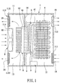
- FIG.1 is an assembled schematic partly sectional view of the preferred embodiment of an air cooling/heating device according to the present invention; and
- FIG.2 is an electric circuit diagram of a power supply unit according to the preferred embodiment.
- As shown in FIG.1, the preferred embodiment of an air cooling/heating device according to the present invention includes a
housing unit 1, a thermal energy storing unit 3, anenergy exchange unit 4, apump 5, a thermoelectric semiconductor device 6, a heat guide 7, aturbulence unit 8, and apower supply unit 2. - The
housing unit 1 includes ahousing body 11, and apartition plate 14 disposed in and connected to thehousing body 11 such that thepartition plate 14 divides an interior of thehousing body 11 into first andsecond compartments housing body 11 is formed with afirst opening 111 and afirst mounting hole 112 in spatial communication with thefirst compartment 12. Thehousing body 11 is further formed with asecond opening unit 113 and asecond mounting hole 114 in spatial communication with thesecond compartment 13. In this embodiment, thesecond opening unit 113 includes second andthird openings second mounting hole 114 is disposed between the second andthird openings housing unit 1 further includesseveral air filters 18 that are disposed to cover the first, second andthird openings - The thermal energy storing unit 3 is mounted to the
partition plate 14 of thehousing unit 1, is disposed in thefirst compartment 12, and is adapted to contain antifreeze liquid. In this embodiment, the thermal energy storing unit 3 is embedded in thepartition plate 14 of thehousing unit 1, and the antifreeze liquid is water mixed with ethylene glycol. - The
energy exchange unit 4 is disposed in thefirst compartment 12, and includes ameandering pipe 41 that is connected to the thermal energy storing unit 3 to form a closed loop therewith. - The
pump 5 is connected in series to thepipe 41 of theenergy exchange unit 4, and is operable to deliver the antifreeze liquid contained in the thermal energy storing unit 3 to theenergy exchange unit 4 and to return the antifreeze liquid in theenergy exchange unit 4 back to the thermal energy storing unit 3. - The thermoelectric semiconductor device 6 is disposed in the
second compartment 13, and has afirst side 61 in thermal contact with the thermal energy storing unit 3. In this embodiment, thesecond mounting hole 114 is registered with the thermoelectric semiconductor device 6. - The heat guide 7 is disposed in the
second compartment 13, and is fixed to asecond side 62 of the thermoelectric semiconductor device 6 that is opposite to thefirst side 61. In this embodiment, the heat guide 7 is a comb-shaped heat sink. - The
turbulence unit 8 includes first andsecond fans second mounting holes housing body 11, respectively. Thefirst fan 81 is operable to draw air out of thefirst compartment 12, and thesecond fan 82 is operable to draw air into thesecond compartment 13. - The
power supply unit 2 is mounted in thehousing unit 1, and is connected electrically to thepump 5. With further reference to FIG.2, thepower supply unit 2 includes a high-voltage low-current circuit, and is responsible for supplying electric power to the various components of the device. - Preferably, a
temperature monitoring unit 9 is attached to the thermal energy storing unit 3, is connected electrically to thepower supply unit 2, and is used to monitor temperature of the antifreeze liquid in the thermal energy storing unit 3. - The thermoelectric semiconductor device 6 is operable to absorb heat at one of the first and
second sides second sides first side 61 absorbs thermal energy, and thesecond side 62 dissipates thermal energy. On the other hand, when the air cooling/heating device is operated in a second mode, thesecond side 62 absorbs thermal energy, and thefirst side 61 dissipates thermal energy. - Take the air cooling/heating device working in the heating mode as an example for the following description on operating principles of the air cooling/heating device. With electrical power supplied by the
power supply unit 2, the thermoelectric semiconductor device 6 is capable of producing a stable heat source at thefirst side 61 thereof such that the thermal energy storing unit 3 is maintained at a heated state. Thepump 5 delivers the heated antifreeze liquid between the thermal energy storing unit 3 and theenergy exchange unit 4 via thepipe 41 such that temperature of air in thefirst compartment 12 is increased by the heated antifreeze liquid. The heated air is drawn out of thefirst compartment 12 by thefirst fan 81 of theturbulence unit 8. As thefirst fan 81 draws the heated air out of thefirst compartment 12, air from outside of the air cooling/heating device is drawn into thefirst compartment 12 through thefirst opening 111 as a result of air circulation. On the other hand, thesecond side 62 of the thermoelectric semiconductor device 6 absorbs thermal energy via the heat guide 7 such that temperature of air in thesecond compartment 13 is decreased. As thesecond fan 82 of theturbulence unit 8 draws air fromoutside of the air cooling/heating device into thesecond compartment 13, the cooled air is drawn out of thesecond compartment 13 via the second andthird openings - On the contrary, by reversing the electrical polarity of the thermoelectric semiconductor device 6 such that the
first side 61 produces a cold source and thesecond side 62 dissipates thermal energy, the air cooling/heating device can effectively operate as an air cooler. - In view of the thermoelectric semiconductor device 6, the air cooling/heating device according to the present invention can provide a large power output while having a compact size and consuming a smaller amount of electricity to reduce manufacturing and operating costs.
Claims (9)
- An air cooling/heating device, characterized by:a housing unit (1) including a housing body (11), and a partition plate (14) disposed in and connected to said housing body (11) such that said partition plate (14) divides an interior of said housing body (11) into first and second compartments (12, 13), said housing body (11) being formed with a first opening (111) and a first mounting hole (112) in spatial communication with said first compartment (12), said housing body (11) being further formed with a second opening unit (113) and a second mounting hole (114) in spatial communication with said second compartment (13);a thermal energy storing unit (3) mounted to said partition plate (14) of said housing unit (1), disposed in said first compartment (12), and adapted to contain antifreeze liquid;an energy exchange unit (4) disposed in said first compartment (12), and including a pipe (41) that is connected to said thermal energy storing unit (3) to form a closed loop therewith;a pump (5) connected in series to said pipe (41) of said energy exchange unit (4), and operable to deliver the antifreeze liquid contained in said thermal energy storing unit (3) to said energy exchange unit (4) and to return the antifreeze liquid in said energy exchange unit (4) back to said thermal energy storing unit (3);a thermoelectric semiconductor device (6) disposed in said second compartment (13), and having a first side (61) in thermal contact with said thermal energy storing unit (3) ; anda turbulence unit (8) including first and second fans (81, 82) mounted in said first and second mounting holes (112, 114) in said housing body (11), respectively.
- The air cooling/heating device as claimed in Claim 1, further characterized by a power supply unit (2) mounted in said housing unit (1) and connected electrically to said pump (5).
- The air cooling/heating device as claimed in Claim 1, further characterized by a heat guide (7) disposed in said second compartment (13), and fixed to a second side (62) of said thermoelectric semiconductor device (6).
- The air cooling/heating device as claimed in Claim 3, characterized in that said heat guide (7) is a comb-shaped heat sink.
- The air cooling/heating device as claimed in Claim 1, characterized in that said second mounting hole (114) is registered with said thermoelectric semiconductor device (6).
- The air cooling/heating device as claimed in Claim 5, characterized in that said second opening unit (113) includes second and third openings (1131, 1132), and that said second mounting hole (114) is disposed between said second and third openings (1131, 1132).
- The air cooling/heating device as claimed in Claim 1, characterized in that said first fan (81) is operable to draw air out of said first compartment (12), and that said second fan (82) is operable to draw air into said second compartment (13).
- The air cooling/heating device as claimed in Claim 3, characterized in that said thermoelectric semiconductor device (6) is operable to absorb heat at one of said first and second sides (61, 62), and to dissipate heat at the other one of said first and second sides (61, 62).
- The air cooling/heating device as claimed in Claim 1, characterized in that said thermal energy storing unit (3) is embedded in said partition plate (14) of said housing unit (1).
Priority Applications (1)
| Application Number | Priority Date | Filing Date | Title |
|---|---|---|---|
| EP06254389A EP1892484A1 (en) | 2006-08-22 | 2006-08-22 | Air cooling/heating device |
Applications Claiming Priority (1)
| Application Number | Priority Date | Filing Date | Title |
|---|---|---|---|
| EP06254389A EP1892484A1 (en) | 2006-08-22 | 2006-08-22 | Air cooling/heating device |
Publications (1)
| Publication Number | Publication Date |
|---|---|
| EP1892484A1 true EP1892484A1 (en) | 2008-02-27 |
Family
ID=37607448
Family Applications (1)
| Application Number | Title | Priority Date | Filing Date |
|---|---|---|---|
| EP06254389A Withdrawn EP1892484A1 (en) | 2006-08-22 | 2006-08-22 | Air cooling/heating device |
Country Status (1)
| Country | Link |
|---|---|
| EP (1) | EP1892484A1 (en) |
Cited By (12)
| Publication number | Priority date | Publication date | Assignee | Title |
|---|---|---|---|---|
| WO2014023034A1 (en) * | 2012-08-06 | 2014-02-13 | 广州市华德工业有限公司 | Air conditioning clod-hot water unit with antifreezing solution regenerative apparatus |
| EP2775250A1 (en) * | 2013-03-06 | 2014-09-10 | BAE Systems PLC | Laminated heat exchanger including a heat sink and a thermoelectric device |
| WO2014135844A1 (en) * | 2013-03-06 | 2014-09-12 | Bae Systems Plc | Laminated heat exchanger including a heat sink and a thermoelectric device |
| JP2014528567A (en) * | 2011-10-12 | 2014-10-27 | リンデール インコーポレイテッド | Indoor cooling system |
| CN106931573A (en) * | 2017-03-16 | 2017-07-07 | 北京工业大学 | Modular portable semiconductor air conditioner |
| RU2679527C1 (en) * | 2018-05-24 | 2019-02-11 | Федеральное государственное бюджетное научное учреждение Федеральный научный агроинженерный центр ВИМ (ФГБНУ ФНАЦ ВИМ) | Thermoelectric plant for air purifying in agricultural premises |
| CN109915965A (en) * | 2017-12-13 | 2019-06-21 | 林世轩 | Fan mechanism with cooling chip cooling |
| US11241332B2 (en) | 2017-05-30 | 2022-02-08 | Recensmedical, Inc. | Handheld medical cooling device for cooling a target area of a subject patient for medical treatment and method thereof |
| US11300340B2 (en) * | 2017-12-29 | 2022-04-12 | Recensmedical, Inc. | Apparatus for generating refrigeration for cooling target and method of cooling target using the same |
| AT524712A1 (en) * | 2021-02-12 | 2022-08-15 | Johann Aschauer | Device for air conditioning a room with an air conditioner |
| US12178965B2 (en) | 2016-11-15 | 2024-12-31 | Recensmedical, Inc. | Local cooling anesthesia device, method of controlling local cooling anesthesia device, and cooling temperature regulator of local cooling anesthesia device |
| WO2025229358A1 (en) * | 2024-05-03 | 2025-11-06 | Anzen Innovations Limited | Climate control apparatus |
Citations (5)
| Publication number | Priority date | Publication date | Assignee | Title |
|---|---|---|---|---|
| DE1801088A1 (en) * | 1968-10-01 | 1970-05-27 | Siemens Ag | Cooling device for building interiors |
| GB2330403A (en) * | 1997-10-20 | 1999-04-21 | Toshiba Kk | Air conditioner |
| US20030145605A1 (en) * | 2002-02-07 | 2003-08-07 | Moon Dong Soo | Air conditioner having thermoelectric module |
| US20060048520A1 (en) * | 2004-09-09 | 2006-03-09 | U-Long Co., Ltd. | Cooling/heating pad |
| DE102005036492A1 (en) * | 2004-07-30 | 2006-03-23 | Herbert Wolf | Interior space e.g. office space, cooling and heating process for use in building, involves causing circulation guidance of cooled water circulation and heat water circulation by cooling water pump and cold water pump |
-
2006
- 2006-08-22 EP EP06254389A patent/EP1892484A1/en not_active Withdrawn
Patent Citations (5)
| Publication number | Priority date | Publication date | Assignee | Title |
|---|---|---|---|---|
| DE1801088A1 (en) * | 1968-10-01 | 1970-05-27 | Siemens Ag | Cooling device for building interiors |
| GB2330403A (en) * | 1997-10-20 | 1999-04-21 | Toshiba Kk | Air conditioner |
| US20030145605A1 (en) * | 2002-02-07 | 2003-08-07 | Moon Dong Soo | Air conditioner having thermoelectric module |
| DE102005036492A1 (en) * | 2004-07-30 | 2006-03-23 | Herbert Wolf | Interior space e.g. office space, cooling and heating process for use in building, involves causing circulation guidance of cooled water circulation and heat water circulation by cooling water pump and cold water pump |
| US20060048520A1 (en) * | 2004-09-09 | 2006-03-09 | U-Long Co., Ltd. | Cooling/heating pad |
Cited By (17)
| Publication number | Priority date | Publication date | Assignee | Title |
|---|---|---|---|---|
| JP2014528567A (en) * | 2011-10-12 | 2014-10-27 | リンデール インコーポレイテッド | Indoor cooling system |
| WO2014023034A1 (en) * | 2012-08-06 | 2014-02-13 | 广州市华德工业有限公司 | Air conditioning clod-hot water unit with antifreezing solution regenerative apparatus |
| EP2775250A1 (en) * | 2013-03-06 | 2014-09-10 | BAE Systems PLC | Laminated heat exchanger including a heat sink and a thermoelectric device |
| WO2014135844A1 (en) * | 2013-03-06 | 2014-09-12 | Bae Systems Plc | Laminated heat exchanger including a heat sink and a thermoelectric device |
| US9921007B2 (en) | 2013-03-06 | 2018-03-20 | Bae Systems Plc | Laminated heat exchanger including a heat sink and a thermoelectric device |
| US12178965B2 (en) | 2016-11-15 | 2024-12-31 | Recensmedical, Inc. | Local cooling anesthesia device, method of controlling local cooling anesthesia device, and cooling temperature regulator of local cooling anesthesia device |
| CN106931573A (en) * | 2017-03-16 | 2017-07-07 | 北京工业大学 | Modular portable semiconductor air conditioner |
| US11241332B2 (en) | 2017-05-30 | 2022-02-08 | Recensmedical, Inc. | Handheld medical cooling device for cooling a target area of a subject patient for medical treatment and method thereof |
| US12239571B2 (en) | 2017-05-30 | 2025-03-04 | Recensmedical, Inc. | Device and method for cooling living tissue |
| CN109915966A (en) * | 2017-12-13 | 2019-06-21 | 林世轩 | Refrigeration assembly and fan mechanism using the same for cooling |
| CN109915965A (en) * | 2017-12-13 | 2019-06-21 | 林世轩 | Fan mechanism with cooling chip cooling |
| US11300340B2 (en) * | 2017-12-29 | 2022-04-12 | Recensmedical, Inc. | Apparatus for generating refrigeration for cooling target and method of cooling target using the same |
| US11774153B2 (en) | 2017-12-29 | 2023-10-03 | Recensmedical, Inc. | Apparatus for providing cooling energy to a target |
| RU2679527C1 (en) * | 2018-05-24 | 2019-02-11 | Федеральное государственное бюджетное научное учреждение Федеральный научный агроинженерный центр ВИМ (ФГБНУ ФНАЦ ВИМ) | Thermoelectric plant for air purifying in agricultural premises |
| AT524712A1 (en) * | 2021-02-12 | 2022-08-15 | Johann Aschauer | Device for air conditioning a room with an air conditioner |
| AT524712B1 (en) * | 2021-02-12 | 2025-06-15 | Johann Aschauer | Device for air conditioning a room with an air conditioner |
| WO2025229358A1 (en) * | 2024-05-03 | 2025-11-06 | Anzen Innovations Limited | Climate control apparatus |
Similar Documents
| Publication | Publication Date | Title |
|---|---|---|
| KR200487943Y1 (en) | Semiconductor-based air conditioning device | |
| EP1892484A1 (en) | Air cooling/heating device | |
| JP3159901U (en) | Battery heat dissipation module for car | |
| JP2011225074A (en) | Heat medium heating device and vehicle air conditioning device using the same | |
| CN219243958U (en) | Semiconductor refrigeration module and optical beauty instrument | |
| US20080041066A1 (en) | Air cooling/heating device | |
| JP2013064538A (en) | Heat pump hot-water supply outdoor unit | |
| KR100886951B1 (en) | Cooling device with thermoelectric element | |
| KR100922104B1 (en) | Heating element cooling device and electronic device having same | |
| CN215820672U (en) | Food processor | |
| KR20020019787A (en) | High efficiency thermoelectric cooling and heating box for food and drink storage in a vehicle | |
| KR20100007295U (en) | electric cool warm vest | |
| KR101057875B1 (en) | Automotive air conditioner and its control method | |
| KR20080017609A (en) | Air cooling / heating unit | |
| CN116336574B (en) | Air conditioner outdoor unit and air conditioner | |
| CN112791313A (en) | LED light source assembly with stable wavelength and intensity and light source system | |
| KR101013931B1 (en) | Automotive cooling device using thermoelectric element | |
| CN210866764U (en) | Laser and refrigerating device thereof | |
| KR20160019712A (en) | Bed Mattress Cooling and Heating Device Using Thermoelement | |
| KR101397086B1 (en) | Cooling apparatus for rack | |
| CN212814357U (en) | Cooling clothes | |
| CN223552596U (en) | A heat dissipation system and an integrated energy storage unit | |
| CN223899110U (en) | A switching power supply with a temperature control mechanism | |
| CN222765247U (en) | Light processing device | |
| CN222765246U (en) | Light processing device |
Legal Events
| Date | Code | Title | Description |
|---|---|---|---|
| PUAI | Public reference made under article 153(3) epc to a published international application that has entered the european phase |
Free format text: ORIGINAL CODE: 0009012 |
|
| AK | Designated contracting states |
Kind code of ref document: A1 Designated state(s): AT BE BG CH CY CZ DE DK EE ES FI FR GB GR HU IE IS IT LI LT LU LV MC NL PL PT RO SE SI SK TR |
|
| AX | Request for extension of the european patent |
Extension state: AL BA HR MK YU |
|
| AKX | Designation fees paid | ||
| REG | Reference to a national code |
Ref country code: DE Ref legal event code: 8566 |
|
| STAA | Information on the status of an ep patent application or granted ep patent |
Free format text: STATUS: THE APPLICATION IS DEEMED TO BE WITHDRAWN |
|
| 18D | Application deemed to be withdrawn |
Effective date: 20080828 |