EP1890168A1 - Laserscanner - Google Patents
Laserscanner Download PDFInfo
- Publication number
- EP1890168A1 EP1890168A1 EP06119147A EP06119147A EP1890168A1 EP 1890168 A1 EP1890168 A1 EP 1890168A1 EP 06119147 A EP06119147 A EP 06119147A EP 06119147 A EP06119147 A EP 06119147A EP 1890168 A1 EP1890168 A1 EP 1890168A1
- Authority
- EP
- European Patent Office
- Prior art keywords
- light
- laser
- rotary body
- rotor
- laser scanner
- Prior art date
- Legal status (The legal status is an assumption and is not a legal conclusion. Google has not performed a legal analysis and makes no representation as to the accuracy of the status listed.)
- Withdrawn
Links
Images


Classifications
-
- G—PHYSICS
- G01—MEASURING; TESTING
- G01S—RADIO DIRECTION-FINDING; RADIO NAVIGATION; DETERMINING DISTANCE OR VELOCITY BY USE OF RADIO WAVES; LOCATING OR PRESENCE-DETECTING BY USE OF THE REFLECTION OR RERADIATION OF RADIO WAVES; ANALOGOUS ARRANGEMENTS USING OTHER WAVES
- G01S17/00—Systems using the reflection or reradiation of electromagnetic waves other than radio waves, e.g. lidar systems
- G01S17/02—Systems using the reflection of electromagnetic waves other than radio waves
- G01S17/06—Systems determining position data of a target
- G01S17/42—Simultaneous measurement of distance and other co-ordinates
-
- G—PHYSICS
- G01—MEASURING; TESTING
- G01S—RADIO DIRECTION-FINDING; RADIO NAVIGATION; DETERMINING DISTANCE OR VELOCITY BY USE OF RADIO WAVES; LOCATING OR PRESENCE-DETECTING BY USE OF THE REFLECTION OR RERADIATION OF RADIO WAVES; ANALOGOUS ARRANGEMENTS USING OTHER WAVES
- G01S17/00—Systems using the reflection or reradiation of electromagnetic waves other than radio waves, e.g. lidar systems
- G01S17/88—Lidar systems specially adapted for specific applications
- G01S17/89—Lidar systems specially adapted for specific applications for mapping or imaging
-
- G—PHYSICS
- G01—MEASURING; TESTING
- G01S—RADIO DIRECTION-FINDING; RADIO NAVIGATION; DETERMINING DISTANCE OR VELOCITY BY USE OF RADIO WAVES; LOCATING OR PRESENCE-DETECTING BY USE OF THE REFLECTION OR RERADIATION OF RADIO WAVES; ANALOGOUS ARRANGEMENTS USING OTHER WAVES
- G01S7/00—Details of systems according to groups G01S13/00, G01S15/00, G01S17/00
- G01S7/48—Details of systems according to groups G01S13/00, G01S15/00, G01S17/00 of systems according to group G01S17/00
- G01S7/481—Constructional features, e.g. arrangements of optical elements
- G01S7/4817—Constructional features, e.g. arrangements of optical elements relating to scanning
-
- G—PHYSICS
- G01—MEASURING; TESTING
- G01S—RADIO DIRECTION-FINDING; RADIO NAVIGATION; DETERMINING DISTANCE OR VELOCITY BY USE OF RADIO WAVES; LOCATING OR PRESENCE-DETECTING BY USE OF THE REFLECTION OR RERADIATION OF RADIO WAVES; ANALOGOUS ARRANGEMENTS USING OTHER WAVES
- G01S7/00—Details of systems according to groups G01S13/00, G01S15/00, G01S17/00
- G01S7/48—Details of systems according to groups G01S13/00, G01S15/00, G01S17/00 of systems according to group G01S17/00
- G01S7/481—Constructional features, e.g. arrangements of optical elements
- G01S7/4818—Constructional features, e.g. arrangements of optical elements using optical fibres
-
- G—PHYSICS
- G02—OPTICS
- G02B—OPTICAL ELEMENTS, SYSTEMS OR APPARATUS
- G02B6/00—Light guides; Structural details of arrangements comprising light guides and other optical elements, e.g. couplings
- G02B6/24—Coupling light guides
- G02B6/26—Optical coupling means
- G02B6/32—Optical coupling means having lens focusing means positioned between opposed fibre ends
-
- G—PHYSICS
- G02—OPTICS
- G02B—OPTICAL ELEMENTS, SYSTEMS OR APPARATUS
- G02B6/00—Light guides; Structural details of arrangements comprising light guides and other optical elements, e.g. couplings
- G02B6/24—Coupling light guides
- G02B6/42—Coupling light guides with opto-electronic elements
- G02B6/4201—Packages, e.g. shape, construction, internal or external details
- G02B6/4204—Packages, e.g. shape, construction, internal or external details the coupling comprising intermediate optical elements, e.g. lenses, holograms
Definitions
- the invention relates to a laser scanner according to the preamble of claim 1.
- 3D laser scanners are typically used. These are placed in one place and scan the 3D scenario from this location.
- the measurement process hereby requires rotations about two orthogonal axes, namely about a perpendicular axis and a horizontal axis rotating about the perpendicular axis.
- the rotation about the Lotachse takes place by the movement of the rotor around the stator, wherein the second axis of rotation is in the rotor.
- the entire transmitting and receiving optics is fixed.
- a deflection mirror is arranged, which is mounted rotatably about a horizontal axis on the rotor.
- the laser light is guided via the transmission optics on the deflection mirror.
- the font DE 295 18 708 U1 describes a theodolite with a telescope that is rotatable about a vertical axis and pivotable about a horizontal axis.
- the theodolite also includes a laser distance measuring device, wherein the laser beam is introduced for the distance measurement in the beam path of the telescope of the theodolite.
- the laser source in the tilt axis of the theodolite is firmly connected to the telescope and the laser beam is reflected over at least one deflecting element in the target axis of the beam path of the telescope.
- an electronic evaluation system is arranged on the telescope.
- the evaluation electronics leads to an increase in the size of the telescope, whereby the telescope already requires too much space for a 3D laser scanner and means additional mass.
- Another disadvantage of the evaluation electronics on the telescope is that the evaluation electronics must be connected via electrical supply and signal lines through the pivot axis of the telescope. If the telescope should be freely rotatable about the horizontal axis, the electrical supply of the laser source must be via a rotary feedthrough respectively.
- the known electrical rotary unions are complex and prone to failure in the rough use of the device.
- An object of the present invention is to provide an improved 3D laser scanner.
- Another object is to provide a 3D laser scanner with increased field capability, in particular greater robustness and lower power consumption.
- the inventive solution is based on the design of the laser scanner with a simple and small constructed, about two orthogonal axes movable optical rotary body, which can be completed and formed without electrical rotary feedthroughs.
- the laser source, the laser detector and the evaluation electronics are housed outside the optical rotary body in a rotor which rotates about the substantially vertical axis.
- a transmission laser beam with essentially rotationally symmetrical beam quality and high power is required.
- Laser sources which meet these requirements are complicated and expensive.
- Cheap diode broad-band emitters can be efficiently coupled with micro-optics to rotationally symmetrical light guides, so that the line focus of the emitter is converted to an approximately square focus.
- the laser light originating from the laser source is guided in the rotor by a light guide from the laser source to the optical link between the rotor and the rotary body.
- a multimode fiber of, for example, 50 ⁇ m core diameter and a numerical aperture of, for example, 0.12 is recommended.
- a low-cost and high-performance diode broadband laser can be efficiently coupled via a simple transmission optics.
- the optical link consists of two fiber ferrules (fiber connectors) with an air gap of a few micrometers, in which one ferrule is fixedly mounted in the rotary body and rotates and the other is held in the rotor directly in the axis of rotation.
- a light guide is arranged only on one side of the optical link.
- optical waveguides in the optical link is advantageous, for example, if they are designed such that a variation of the angle of incidence of the light in the optical waveguide on the side of the rotary head has a negligible influence on the position of the beam axis at its fiber end. With such an optical design can be achieved that an eccentricity of the associated mechanical axis of rotation does not affect the position of the optical axis at this point.
- the position of the optical axes from the transmitted to the receiving beam in the rotary head remains unaffected by an eccentricity of the corresponding axis of rotation.
- this uncertainty in the dimensioning of the opening angle of the receiving optics must not be considered and can finally be made smaller.
- the received background light can be minimized, which ultimately leads to an increase in the sensitivity and accuracy of the distance meter.
- a coating of the ferrule surfaces is used to increase the coupling efficiency and suppress possible interfering etalon effects. If a larger air gap is required, for example because of the tolerances in the rotational movement, so can
- the optical link can also be constructed via two small collimating optics, which also allow a very good coupling efficiency.
- the transmitted light is guided centrally out of the measuring head, for example via two mirrors and a simple collimation optics.
- the receiving optics in particular also includes an optical system and two mirrors and is aligned on the same axis. Because of the required larger receiving aperture, the receiving optics in particular uses the outer area of the optics.
- the rotary body compact and small, so that, for example, rotary bodies having a diameter in the direction of the rotary body rotation axis of only 5 cm and perpendicular to the optical system with a height of only 4 cm can be realized.
- the laser light originating from the laser source reaches the object area via the mirrors and the central area of the optics.
- the backscattered laser light passes through the radially outer region of the optics and two mirrors in an optical fiber, which leads to the optical exit link between the rotating body and rotor.
- the receiving electronics can be arranged directly at the exit link.
- an optical fiber leads from the exit link to the evaluation electronics. If the detector and the laser source are connected to the common evaluation electronics in the rotor, the distance measurement can be carried out efficiently.
- Fig. 1 shows a rotor 1, on which a rotary body 2 is rotatably mounted about a horizontal axis on the pivot bearings 3.
- a first rotary drive not shown here, the rotor 1 is movable about a vertical axis, wherein the rotational position can be determined by a first protractor.
- a second rotary drive 26 the rotary body 2 is rotated. The rotational position of the rotating body 2 is detected by a second protractor 4.
- An evaluation electronics 5 in the rotor 1 is with a laser source 6 (laser) and a laser light detector 7 (APD) of the distance measuring device connected.
- laser laser source 6
- APD laser light detector
- the laser light originating from the laser source 6 is guided in the rotor 1 through an optical waveguide 8 from the laser source 6 to an optical link 9 between the rotor 1 and the rotary body 2.
- a multimode fiber of, for example, 50 ⁇ m core diameter and a numerical aperture of, for example, 0.12 is recommended.
- the optical link 9 comprises two fiber ferrules 10 (fiber connectors) and an air gap of a few micrometers, wherein the one ferrule is fixedly mounted in the rotary body 2 and rotates and the other is supported in the rotor 1 directly in the axis of rotation.
- the optical link 9 also comprises a lens 11 for optimal transmission of the laser light.
- a light guide 8 guides the transmitted light to an exit point 16 from which it exits the rotary body 2 via two first mirrors 12 and one central lens 13.
- the two first mirrors 12 are arranged in the rotary body 2 at a passage boundary 33.
- the transmission light is conducted between the two first mirrors 12 from a lateral area to the central lens 13.
- the laser light scattered back from the object area passes through a ring lens 14 and two second mirrors 15 to an entry point 17 of a light guide 8.
- the received light arrives at the detector 7 via an optical link 9 and the adjoining light guide 8.
- the evaluation electronics determines signals from the signals Laser source 6 and the detector 7 distance values, which are assigned to the corresponding Drehauscardi the second protractor 4.
- the orientation of the rotor 1 relative to a stator is detected by a first protractor, not shown. Each detected distance value may be associated with a spatial orientation determined by two alignment values.
- the transmission optics with a focal length of 50 mm requires an exit pupil of 12 mm diameter.
- the optics can be a multiple lens or consist of an (aspheric) Einzellinse.
- the receiving optics are designed with a focal length of 80 mm and a diameter of 30 mm significantly larger and receives the transmission optics in the central area.
- a through-bore of the receiving lens with the transmitting optics is suitable as a slot, or a complex glass press with two different focal lengths, or the combination of the receiving optics with a diffractive element in the central region, to achieve a higher refractive power.
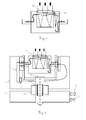
- Fig. 3 Also feasible is a design of the optics as shown in Fig. 3, in which the same front lens 13a is used for receiving and transmitting optics, in conjunction with another lens element 13b in the transmission channel, resulting in the desired shortened focal length.
- the received light is imaged via a folded beam path, consisting of two second mirrors 15, onto a light guide 8 with a core diameter of 200 ⁇ m.
- the second mirrors 15 may also be curved to further reduce the size of the structure.
- the received light is conducted via an optical link 9, which is designed similarly to the transmission channel, in the rotor 1 to a detector 7. All electronic components can thus be kept outside the rotary body 2.
- the transmitting and receiving optics always remain aligned with each other in contrast to previous embodiments in which the mirror is permanently moved relative to the rest of the optics, which leads to constantly changing imaging situations and is relatively easy to adjust or error prone.
- Fig. 2 shows a laser source 6 in the form of a diode broad-band emitter 18 with dimensions of 60 ⁇ m wide (slow axis) and 2 ⁇ m narrow (fast axis).
- the laser light of this emitter is coupled with a micro-optics in the rotationally symmetrical light guide 8 with a diameter of 50 microns.
- the micro-optics of Embodiment comprises a cylindrical lens 19 and a spherical lens 20, wherein the line focus of the emitter 18 is converted to an approximately square focus.
- A. of the arrow Beam shaping of wide area laser diode: principles and benefits", Proc. SPIE Vol. 4648 Test and Measurement Applications of Optoelectronic Devices , Segmenting beamforming optics are known. These new optics can stack a line focus in sections to a square focus.
- a laser scanner thus comprises the stator 21, the rotor 1 rotatably mounted on the stator 21 about a first rotation axis, the rotary body 2 rotatably mounted on the rotor 1 about a second rotation axis, the evaluation electronics 5, the laser source 6 and the laser light detector 7
- the passage of transmitted light and received light, the rotary body 2 comprises a parallel to the second axis of rotation füreriesberandung 33rd
- a desired scanning movement is effected by a corresponding control of the first rotary drive 25 and the second rotary drive 26.
- the spatial orientation of the rotary body 2 is detected by the two protractors 4.
- the detector 7 is arranged directly at the optical link 9. This makes it possible to dispense with a light guide for the transmission of the received light from the optical link 9 to the detector.
- the rear second mirror 15 of the receiving optics is partially transparent. Behind this partially transmissive second mirror 15, a deflection mirror 27 and a compact CCD camera 28 can be installed in the rotary body 2.
- the camera 28 allows a visual inspection of the receiving channel.
- a rotary feedthrough 29 is used for the camera 28.
- the power supply of the camera 28 can also be done optically by light in the fiber zw.
- Laseretti 6 and the link 9 via a chromatic beam splitter light of a different wavelength from a separate source (100 mW) is coupled and in the turret over a same beam splitter again decoupled and directed to a photovoltaic component or solar cell, which takes over the necessary supply to the camera.
- the data transmission can optically via a modulated signal again via a beam splitter via output fiber.
- Corresponding low-current components are known and available, for example, from mobile radio technology.
- the texture of the object to be scanned can be detected.
- a simple spectral sensor can also be used. Set the entire scene to be scanned in advance can be detected quickly, as well as in the rotor (1) laterally adjacent to the rotor body (2) arranged camera with a corresponding zoom optics can be realized.
- a reference unit 30 similar to the embodiment in DE 102 16 405 be grown to allow a complete calibration of the distance measuring device.
- the reference unit 30 consists in the simplest case of a target in the known distance to obtain a distance standard during rotation of the measuring head.
- the reflectivity of the target may vary to allow dynamic distance calibration.
- the solid-state laser 31 is, for example, a ⁇ -chip laser (Nd: YAG) Q-switched with a saturable absorber (Cr 4+ : YAG). Because of the high peak power in the kW range, a fiber transmission due to the damage threshold is critical.
- the pump light from the pump laser 6 (808 nm) can be guided via the optical link 9 into the rotary body 2 and there excite the solid-state laser 31.
- the exiting laser light does not have to be guided through a lens but can emerge from the rotary body 2 through an exit hole 32.
- any other beam path for example with transmit beam path and receive beam path can be provided laterally side by side instead of the described folded beam path.
Abstract
Description
Die Erfindung bezieht sich auf einen Laserscanner nach dem Oberbegriff des Anspruches 1.The invention relates to a laser scanner according to the preamble of claim 1.
Zur Erfassung einer räumlichen Umgebung werden typischerweise sogenannte 3D-Laserscanner eingesetzt. Diese werden an einem Ort aufgestellt und tasten das 3D Szenario von diesem Ort aus ab. Der Messablauf erfordert hierbei Drehungen um zwei orthogonale Achsen, nämlich um eine Lotachse und eine um die Lotachse drehende horizontale Achse. Die Drehung um die Lotachse erfolgt durch die Bewegung des Rotors um den Stator, wobei sich die zweite Drehachse im Rotor befindet.To capture a spatial environment, so-called 3D laser scanners are typically used. These are placed in one place and scan the 3D scenario from this location. The measurement process hereby requires rotations about two orthogonal axes, namely about a perpendicular axis and a horizontal axis rotating about the perpendicular axis. The rotation about the Lotachse takes place by the movement of the rotor around the stator, wherein the second axis of rotation is in the rotor.
Bei Ausführungsformen gemäss der
Einen weiteren Nachteil stellt die Offenheit des optischen Aufbaus dar, da der Spiegel innerhalb des optischen Aufbaus frei beweglich sein muss. Die Abdeckung des Systems gegenüber Staub und andere Umwelteinflüsse ist daher einerseits erforderlich, generiert aber anderseits wieder das beschriebene Streulicht-Problem beim Strahlaustritt.Another disadvantage is the openness of the optical design, since the mirror must be free to move within the optical structure. The coverage of the system against dust and other environmental influences is therefore required on the one hand, but on the other hand generates again the described scattered light problem in the beam exit.
Die Schrift
Die Auswertungselektronik führt zu einer Erhöhung der Baugrösse des Fernrohres, wobei bereits das Fernrohr für einen 3D-Laserscanner zu viel Platz benötigt und zusätzliche Masse bedeutet. Ein weiterer Nachteil der Auswertungselektronik am Fernrohr besteht darin, dass die Auswertungselektronik über elektrische Versorgungs- und über Signalleitungen durch die Schwenkachse des Fernrohres verbunden werden muss. Wenn das Fernrohr um die horizontale Achse frei drehbar sein soll, so muss die elektrische Speisung der Laserquelle über eine Drehdurchführung erfolgen. Die bekannten elektrischen Drehdurchführungen sind aufwendig und im rauen Einsatz des Gerätes störungsanfällig.The evaluation electronics leads to an increase in the size of the telescope, whereby the telescope already requires too much space for a 3D laser scanner and means additional mass. Another disadvantage of the evaluation electronics on the telescope is that the evaluation electronics must be connected via electrical supply and signal lines through the pivot axis of the telescope. If the telescope should be freely rotatable about the horizontal axis, the electrical supply of the laser source must be via a rotary feedthrough respectively. The known electrical rotary unions are complex and prone to failure in the rough use of the device.
Eine Aufgabe der vorliegenden Erfindung besteht darin einen verbesserten 3D-Laserscanner bereitzustellen.An object of the present invention is to provide an improved 3D laser scanner.
Eine weitere Aufgabe besteht in der Bereitstellung eines 3D-Laserscanners mit erhöhter Feldtauglichkeit, insbesondere grösserer Robustheit und geringerem Stromverbrauch.Another object is to provide a 3D laser scanner with increased field capability, in particular greater robustness and lower power consumption.
Diese Aufgaben werden durch die Merkmale des Anspruches 1 oder der abhängigen Ansprüche gelöst bzw. weitergebildet.These objects are achieved or developed by the features of claim 1 or the dependent claims.
Die erfinderische Lösung basiert auf der Auslegung des Laserscanners mit einem möglichst einfach und klein aufgebauten, um zwei orthogonale Achsen beweglichen optischen Drehkörpers, der abgeschlossen und ohne elektrische Drehdurchführungen ausgebildet werden kann. Die Laserquelle, der Laser-Detektor und die Auswertungselektronik werden ausserhalb des optischen Drehkörpers in einem Rotor untergebracht, der um die im wesentlichen vertikale Achse dreht.The inventive solution is based on the design of the laser scanner with a simple and small constructed, about two orthogonal axes movable optical rotary body, which can be completed and formed without electrical rotary feedthroughs. The laser source, the laser detector and the evaluation electronics are housed outside the optical rotary body in a rotor which rotates about the substantially vertical axis.
Von der Laserquelle im Rotor muss lediglich ein Lasersignal in den optischen Drehkörper eingebracht werden. Vom optischen Drehkörper wiederum muss lediglich das empfangene Laserlicht in den Rotor übertragen werden. Diese beiden Lasersignale können auf je einer Seite des optischen Drehkörpers zentral entlang der Drehachse des Drehkörpers übertragen werden. Das Sende- und Empfangslicht wird über sogenannte optische Verbindungen bzw. Links in den drehbaren optischen Messkopf ein- bzw. aus diesem ausgekoppelt. Der Messkopf ist dadurch komplett passiv und bedarf keiner elektrischen Versorgungs- oder Signalübertragung.From the laser source in the rotor only a laser signal must be introduced into the optical rotary body. From the optical rotary body in turn, only the received laser light must be transmitted into the rotor. These two laser signals can be transmitted centrally on each side of the optical rotary body along the axis of rotation of the rotary body. The transmitting and receiving light is via so-called optical links or links in the rotatable optical measuring head on or decoupled from this. The measuring head is thus completely passive and requires no electrical supply or signal transmission.
Für eine gute Distanzmessvorrichtung wird ein Sendelaserstrahl mit im wesentlichen rotationssymmetrischer Strahlqualität und hoher Leistung benötigt. Laserquellen, welche diesen Anforderungen genügen, sind aufwendig und teuer. Günstige Dioden-Breitstreifenemitter können mit einer Mikrooptik effizient an rotationssymmetrische Lichtleiter gekoppelt werden, so dass der Linienfokus des Emitters zu einem etwa quadratischen Fokus umgeformt wird.For a good distance measuring device, a transmission laser beam with essentially rotationally symmetrical beam quality and high power is required. Laser sources which meet these requirements are complicated and expensive. Cheap diode broad-band emitters can be efficiently coupled with micro-optics to rotationally symmetrical light guides, so that the line focus of the emitter is converted to an approximately square focus.
Das von der Laserquelle stammende Laserlicht wird im Rotor durch einen Lichtleiter von der Laserquelle zum optischen Link zwischen Rotor und Drehkörper geführt. Dazu bietet sich eine Multimodefaser von beispielsweise 50 µm Kerndurchmesser und einer numerischen Apertur von beispielsweise 0.12 an. In eine solche Faser lässt sich ein kostengünstiger und leistungsstarker Dioden-Breitstreifenlaser über eine einfache Übertragungsoptik effizient einkoppeln.The laser light originating from the laser source is guided in the rotor by a light guide from the laser source to the optical link between the rotor and the rotary body. For this purpose, a multimode fiber of, for example, 50 μm core diameter and a numerical aperture of, for example, 0.12 is recommended. In such a fiber, a low-cost and high-performance diode broadband laser can be efficiently coupled via a simple transmission optics.
In der einfachsten Form besteht der optische Link aus zwei Faserferrulen (Fasersteckern) mit einem Luftspalt von wenigen Mikrometern, bei dem die eine Ferrule fest im Drehkörper montiert ist und sich mitdreht und die andere im Rotor direkt in der Drehachse gehaltert ist. Gegebenenfalls ist lediglich auf einer Seite des optischen Links ein Lichtleiter angeordnet. Beim Einbringen des Sendelichts in den Drehkörper kann das eintretende Licht im Drehkörper gegebenenfalls direkt auf ein Umlenkelement gelangen, so dass auf einen innen an den optischen Link anschliessenden Lichtleiter verzichtet werden kann. Beim Austragen des Empfangslichts aus dem Drehkörper kann das austretende Licht im Rotor gegebenenfalls direkt auf den Detektor gelangen, so dass auf einen aussen an den optischen Link anschliessenden Lichtleiter verzichtet werden kann.In the simplest form, the optical link consists of two fiber ferrules (fiber connectors) with an air gap of a few micrometers, in which one ferrule is fixedly mounted in the rotary body and rotates and the other is held in the rotor directly in the axis of rotation. Optionally, a light guide is arranged only on one side of the optical link. When introducing the transmitted light into the rotary body, the incoming light in the rotary body can possibly pass directly to a deflecting element, see above that it is possible to dispense with a light guide which adjoins the optical link on the inside. When discharging the receiving light from the rotary body, the exiting light in the rotor may optionally pass directly to the detector, so that it is possible to dispense with an optical fiber which adjoins the optical link on the outside.
Die Verwendung von Lichtwellenleitern im optischen Link ist beispielsweise vorteilhaft, wenn diese derart ausgelegt sind, dass eine Variation des Einfallswinkels des Lichts in den Lichtwellenleiter auf der Seite des Drehkopfs einen vernachlässigbaren Einfluss auf die Lage der Strahlachse an dessen Faserende hat. Mit einer derartigen optischen Auslegung kann erreicht werden, dass eine Exzentrizität der zugehörigen mechanischen Rotationsachse sich nicht an diesem Punkt auf die Lage der optischen Achse auswirken.The use of optical waveguides in the optical link is advantageous, for example, if they are designed such that a variation of the angle of incidence of the light in the optical waveguide on the side of the rotary head has a negligible influence on the position of the beam axis at its fiber end. With such an optical design can be achieved that an eccentricity of the associated mechanical axis of rotation does not affect the position of the optical axis at this point.
Wird der optische Link im Empfangskanal entsprechend realisiert, so bleibt die Lage der optischen Achsen von Sende- zu Empfangsstrahl im Drehkopf unbeeinflusst von einer Exzentrizität der entsprechenden Rotationsachse. Somit muss diese Unsicherheit bei der Dimensionierung des Öffnungswinkels der Empfangsoptik nicht berücksichtigt werden und kann schliesslich kleiner ausgelegt werden. Damit kann das empfangene Hintergrundlicht minimiert werden, was schliesslich zu einer Erhöhung der Empfindlichkeit und Genauigkeit des Distanzmessers führt.If the optical link in the receiving channel is realized accordingly, the position of the optical axes from the transmitted to the receiving beam in the rotary head remains unaffected by an eccentricity of the corresponding axis of rotation. Thus, this uncertainty in the dimensioning of the opening angle of the receiving optics must not be considered and can finally be made smaller. Thus, the received background light can be minimized, which ultimately leads to an increase in the sensitivity and accuracy of the distance meter.
In einer bevorzugten Ausführungsform wird eine Beschichtung der Ferrulenflächen eingesetzt, um die Kopplungseffizienz zu erhöhen und mögliche störende Etaloneffekte zu unterdrücken. Ist ein größerer Luftspalt erforderlich, zum Beispiel wegen der Toleranzen in der Drehbewegung, so kann der optische Link auch über zwei kleine Kollimationsoptiken aufgebaut werden, die ebenfalls eine sehr gute Kopplungseffizienz erlauben.In a preferred embodiment, a coating of the ferrule surfaces is used to increase the coupling efficiency and suppress possible interfering etalon effects. If a larger air gap is required, for example because of the tolerances in the rotational movement, so can The optical link can also be constructed via two small collimating optics, which also allow a very good coupling efficiency.
Nach Passage einer kurzen Faserstrecke im Messkopf wird das Sendelicht beispielsweise über zwei Spiegel und eine einfache Kollimationsoptik zentral aus dem Messkopf geführt. Die Empfangsoptik umfasst insbesondere auch eine Optik sowie zwei Spiegel und ist auf die gleiche Achse ausgerichtet. Wegen der benötigten grösseren Empfangsapertur verwendet die Empfangsoptik insbesondere den äußeren Bereich der Optik.After passage of a short fiber span in the measuring head, the transmitted light is guided centrally out of the measuring head, for example via two mirrors and a simple collimation optics. The receiving optics in particular also includes an optical system and two mirrors and is aligned on the same axis. Because of the required larger receiving aperture, the receiving optics in particular uses the outer area of the optics.
Mit diesem Aufbau ist es möglich den Drehkörper kompakt und klein zu bauen, so dass beispielsweise Drehkörper mit einem Durchmesser in Richtung der Drehkörper Drehachse von lediglich 5cm und senkrecht zur Optik mit einer Höhe von lediglich 4cm realisierbar sind. Das von der Laserquelle stammende Laserlicht gelangt über die Spiegel und den zentralen Bereich der Optik auf einen Objektbereich. Das zurück gestreute Laserlicht gelangt durch den radial äusseren Bereich der Optik und zwei Spiegel in einen Lichtleiter, der zum optischen Austrittslink zwischen Drehkörper und Rotor führt.With this structure, it is possible to make the rotary body compact and small, so that, for example, rotary bodies having a diameter in the direction of the rotary body rotation axis of only 5 cm and perpendicular to the optical system with a height of only 4 cm can be realized. The laser light originating from the laser source reaches the object area via the mirrors and the central area of the optics. The backscattered laser light passes through the radially outer region of the optics and two mirrors in an optical fiber, which leads to the optical exit link between the rotating body and rotor.
Die Empfangselektronik kann gegebenenfalls direkt beim Austrittslink angeordnet sein. Vorzugsweise aber führt ein Lichtleiter vom Austrittslink zur Auswertungselektronik. Wenn der Detektor und die Laserquelle an der gemeinsamen Auswertungselektronik im Rotor angeschlossen sind, so kann die Distanzmessung effizient durchgeführt werden.If necessary, the receiving electronics can be arranged directly at the exit link. Preferably, however, an optical fiber leads from the exit link to the evaluation electronics. If the detector and the laser source are connected to the common evaluation electronics in the rotor, the distance measurement can be carried out efficiently.
Die Zeichnungen erläutern die Erfindung anhand von Ausführungsbeispielen schematisch. Dabei zeigt
- Fig. 1
- einen schematischen Vertikalschnitt durch den Rotor und den darin gelagerten Drehkörper;
- Fig. 2
- zwei schematische Längsschnitte durch einen Dioden-Breitstreifenemitter, eine Mikrooptik und einen rotationssymmetrische Lichtleiter;
- Fig. 3
- einen schematischen Vertikalschnitt durch den Drehkörper;
- Fig. 4
- einen schematischen Vertikalschnitt durch eine Ausführungsform gemäss Fig. 1 mit einem Stator;
- Fig. 5
- einen schematischen Vertikalschnitt einer Ausführungsform mit einer Kamera und
- Fig. 6
- einen schematischen Vertikalschnitt einer Ausführungsform mit einem gepumpten Festkörper-Laser.
- Fig. 1
- a schematic vertical section through the rotor and the rotary body mounted therein;
- Fig. 2
- two schematic longitudinal sections through a diode wide strip emitter, a micro-optics and a rotationally symmetrical light guide;
- Fig. 3
- a schematic vertical section through the rotary body;
- Fig. 4
- a schematic vertical section through an embodiment of Figure 1 with a stator ..;
- Fig. 5
- a schematic vertical section of an embodiment with a camera and
- Fig. 6
- a schematic vertical section of an embodiment with a pumped solid-state laser.
Fig. 1 zeigt einen Rotor 1, an dem ein Drehkörper 2 um eine horizontale Achse an den Drehlagern 3 drehbar gelagert ist. Durch einen hier nicht dargestellten ersten Drehantrieb ist der Rotor 1 um eine Stehachse bewegbar, wobei die Drehlage durch einen ersten Winkelmesser bestimmbar ist. Mit einem zweiten Drehantrieb 26 wird der Drehkörper 2 in Drehung versetzt. Die Drehlage des Drehkörpers 2 wird von einem zweiten Winkelmesser 4 erfasst. Eine Auswertungselektronik 5 im Rotor 1 ist mit einer Laserquelle 6 (Laser) und einem Laserlicht-Detektor 7 (APD) der Distanzmessvorrichtung verbunden.Fig. 1 shows a rotor 1, on which a rotary body 2 is rotatably mounted about a horizontal axis on the pivot bearings 3. By a first rotary drive not shown here, the rotor 1 is movable about a vertical axis, wherein the rotational position can be determined by a first protractor. With a second
Das von der Laserquelle 6 stammende Laserlicht wird im Rotor 1 durch einen Lichtleiter 8 von der Laserquelle 6 zu einem optischen Link 9 zwischen Rotor 1 und Drehkörper 2 geführt. Dazu bietet sich eine Multimodefaser von beispielsweise 50 µm Kerndurchmesser und einer numerischen Apertur von beispielsweise 0,12 an.The laser light originating from the
Der optische Link 9 umfasst zwei Faserferrulen 10 (Fasersteckern) und einen Luftspalt von wenigen Mikrometern, wobei die eine Ferrule fest im Drehkörper 2 montiert ist und sich mitdreht und die andere im Rotor 1 direkt in der Drehachse gehaltert ist. In der dargestellten Ausführungsform umfasst der optische Link 9 zur optimalen Übertragung des Laserlichts zudem noch eine Linse 11.The
Im Drehkörper 2 führt ein Lichtleiter 8 das Sendelicht zu einer Austrittsstelle 16, von der es über zwei erste Spiegel 12 und eine zentrale Linse 13 aus dem Drehkörper 2 austritt. Die beiden ersten Spiegel 12 sind im Drehkörper 2 bei einer Durchtrittsberandung 33 angeordnet. Das Sendelicht wird zwischen den beiden ersten Spiegeln 12 von einem seitlichen Bereich zur zentralen Linse 13 geleitet.In the rotary body 2, a
Das vom Objektbereich zurück gestreute Laserlicht gelangt durch eine Ringlinse 14 und zwei zweite Spiegel 15 zu einer Eintrittsstelle 17 eines Lichtleiters 8. Über einen optischen Link 9 und den anschliessenden Lichtleiter 8 gelangt das Empfangslicht zum Detektor 7. Die Auswertungselektronik ermittelt aus Signalen der Laserquelle 6 und des Detektors 7 Distanzwerte, die der entsprechenden Drehausrichtung des zweiten Winkelmessers 4 zugeordnet werden. Die Ausrichtung des Rotors 1 relativ zu einem Stator wird von einem nicht dargestellten ersten Winkelmesser erfasst. Jeder erfasste Distanzwert kann einer durch zwei Ausrichtungswerte bestimmten räumlichen Ausrichtung zugeordnet werden.The laser light scattered back from the object area passes through a ring lens 14 and two second mirrors 15 to an entry point 17 of a
In der dargestellten Ausführungsform des Drehkörpers sind unterschiedliche Brennweiten für die Sende- und Empfangsoptik vorgesehen. Die Sendeoptik mit einer Brennweite von 50 mm bedarf einer Austrittspupille von 12 mm Durchmesser. Die Optik kann ein Mehrlinser sein oder aus einer (asphärischen) Einzellinse bestehen. Die Empfangsoptik ist mit einer Brennweite von 80 mm und einem Durchmesser von 30 mm deutlich größer ausgelegt und nimmt im Zentralbereich die Sendeoptik auf. Hierfür ist eine Durchbohrung der Empfangslinse mit der Sendeoptik als Einschub geeignet, oder eine komplexe Glaspressung mit zwei unterschiedlichen Brennweitenbereichen, oder die Kombination der Empfangsoptik mit einem diffraktiven Element im Zentralbereich, um hier eine höhere Brechkraft zu erzielen.In the illustrated embodiment of the rotary body different focal lengths for the transmitting and receiving optics are provided. The transmission optics with a focal length of 50 mm requires an exit pupil of 12 mm diameter. The optics can be a multiple lens or consist of an (aspheric) Einzellinse. The receiving optics are designed with a focal length of 80 mm and a diameter of 30 mm significantly larger and receives the transmission optics in the central area. For this purpose, a through-bore of the receiving lens with the transmitting optics is suitable as a slot, or a complex glass press with two different focal lengths, or the combination of the receiving optics with a diffractive element in the central region, to achieve a higher refractive power.
Realisierbar ist auch eine Auslegung der Optik wie in Fig. 3 dargestellt, bei der die gleiche Frontlinse 13a für Empfangs- und Sendeoptik genutzt wird, in Verbindung mit einem weiteren Linsenelement 13b im Sendekanal, was die gewünschte verkürzte Brennweite ergibt.Also feasible is a design of the optics as shown in Fig. 3, in which the same front lens 13a is used for receiving and transmitting optics, in conjunction with another
Da die Eigenschaften der Optik stark abhängig sind von der Sendeleistung, den Kerndurchmessern der Fasern, der noch zu messenden maximalen Distanz, der Albedo des Targets, der Empfindlichkeit des Detektors und dem Messprinzip im allgemeinen, sind andere Ausführungsformen der Optik durch den Fachmann ableitbar.Since the properties of the optics are strongly dependent on the transmission power, the core diameters of the fibers, the maximum distance still to be measured, the albedo of the target, the Sensitivity of the detector and the measuring principle in general, other embodiments of the optics are derivable by the skilled person.
Das empfangene Licht wird über einen gefalteten Strahlengang, bestehend aus zwei zweiten Spiegeln 15, auf einen Lichtleiter 8 mit einem Kerndurchmesser von 200 µm abgebildet. Die zweiten Spiegel 15 können auch gekrümmt sein, um den Aufbau weiter zu verkleinern. Das Empfangslicht wird über einen optischen Link 9, der ähnlich ausgebildet ist wie beim Sendekanal, im Rotor 1 auf einen Detektor 7 geleitet. Sämtliche Elektronikkomponenten können somit außerhalb des Drehkörpers 2 gehalten werden.The received light is imaged via a folded beam path, consisting of two second mirrors 15, onto a
Innerhalb des Drehkörpers 2 gibt es keinen Überlapp der Strahlengänge für Sende- und Empfangskanal was das Risiko für Streulicht deutlich reduziert. Der gesamte optische Aufbau befindet sich gekapselt im Drehkörper 2 und ist damit gegenüber Umwelteinflüssen optimal geschützt. Eine äußere Abdeckung ist nicht erforderlich. Unabhängig vom Drehwinkel bleibt die Sende und Empfangsoptik immer gleich zueinander ausgerichtet im Gegensatz zu bisherigen Ausführungsformen, bei denen der Spiegel relativ zum Rest der Optik permanent bewegt wird, was zu ständig sich ändernden Abbildungssituationen führt und relativ justage- bzw. fehleranfällig ist.Within the rotary body 2, there is no overlap of the beam paths for transmitting and receiving channel which significantly reduces the risk of stray light. The entire optical structure is encapsulated in the rotary body 2 and is thus optimally protected against environmental influences. An outer cover is not required. Regardless of the angle of rotation, the transmitting and receiving optics always remain aligned with each other in contrast to previous embodiments in which the mirror is permanently moved relative to the rest of the optics, which leads to constantly changing imaging situations and is relatively easy to adjust or error prone.
Fig. 2 zeigt eine Laserquelle 6 in der Form eines Dioden-Breitstreifenemitters 18 mit Ausdehnungen von 60 µm breit (slow axis) und 2 µm schmal (fast axis). Das Laserlicht dieses Emitters wird mit einer Mikrooptik in den rotationssymmetrischen Lichtleiter 8 mit einem Durchmesser von 50 µm eingekoppelt. Die Mikrooptik des Ausführungsbeispiels umfasst eine zylindrische Linse 19 und eine sphärische Linse 20, wobei der Linienfokus des Emitters 18 zu einem etwa quadratischen Fokus umgeformt wird. Aus dem Stande der Technik, beispielsweise aus
Weitere Ausführungsformen finden sich in den Abbildungen 4 und 5. In diesen ist nun auch das Gesamtsystem mit der Lagerung des Rotors 1 auf einem Stator 21 zu erkennen sowie eine elektrische Versorgung 22 und eine Kommunikationsschnittstelle 23. Zur Drehlagerung des Rotors 1 am Stator 21 ist ein Lager 24 vorgesehen. Der Rotor 1 wird von einem ersten Drehantrieb 25 in Drehung versetzt.Further embodiments can be found in Figures 4 and 5. In these now, the entire system with the bearing of the rotor 1 on a
Ein erfindungsgemässer Laserscanner umfasst somit den Stator 21, den am Stator 21 um eine erste Drehachse drehbar gelagerten Rotor 1, den am Rotor 1 um eine zweite Drehachse drehbar gelagerten Drehkörper 2, die Auswertungselektronik 5, die Laserquelle 6 und den Laserlicht-Detektor 7. Für den Durchtritt von Sendelicht und Empfangslicht umfasst der Drehkörper 2 eine zur zweiten Drehachse parallele Durchtrittsberandung 33.A laser scanner according to the invention thus comprises the
Eine gewünschte Scanbewegung erfolgt durch eine entsprechende Steuerung des ersten Drehantriebs 25 und des zweiten Drehantriebs 26. Die räumliche Ausrichtung des Drehkörpers 2 wird über die beiden Winkelmesser 4 erfasst. Durch die Verbindung der Auswertungselektronik 5 mit der Laserquelle 6, dem Detektor 7 und den Winkelmessern 4 kann eine erfasste Distanz einer entsprechenden Ausrichtung zugeordnet werden.A desired scanning movement is effected by a corresponding control of the first
In der Ausführungsform gemäss Fig. 4 ist der Detektor 7 direkt beim optischen Link 9 angeordnet. Dadurch kann auf einen Lichtleiter für die Übertragung des Empfangslichts vom optischen Link 9 zum Detektor verzichtet werden.In the embodiment according to FIG. 4, the detector 7 is arranged directly at the
In der Ausführungsform gemäss Fig. 5 ist der rückwärtige zweite Spiegel 15 der Empfangsoptik teildurchlässig. Hinter diesem teildurchlässigen zweiten Spiegel 15 lassen sich im Drehkörper 2 ein Umlenkspiegel 27 und eine kompakte CCD-Kamera 28 installieren. Die Kamera 28 ermöglicht eine optische Überprüfung des Empfangskanals. Um die Kamera 28 im Drehkörper 2 betreiben zu können, wird eine Drehdurchführung 29 für die Kamera 28 verwendet. Die Stromversorgung der Kamera 28 kann jedoch ebenfalls auch optisch erfolgen, indem in die Faser zw. Laserquelle 6 und den Link 9 über einen chromatischen Beamsplitter Licht einer anderen Wellenlänge von einer separaten Quelle (100 mW) eingekoppelt wird und im Drehkopf über einen gleichen Beamsplitter wieder ausgekoppelt und auf eine photovoltaische Komponente oder Solarzelle geleitet wird, welche die nötige Versorgung der Kamera übernimmt. Die Datenübertragung kann optisch über ein moduliertes Signal auch wieder über einen Beamsplitter via Ausgangsfaser erfolgen. Entsprechende Schwachstromkomponenten sind z.B. aus der Mobilfunktechnik bekannt und erhältlich. Mit Hilfe der Kamera kann die Textur des zu scannenden Objektes erfasst werden. Als Alternative oder in Ergänzung der Kamera kann auch ein einfacher spektraler Sensor verwendet werden. Soll die gesamte zu scannende Szenerie vorab schnell erfasst werden, so ist auch eine in dem Rotor (1) seitlich neben dem Rotorkörper (2) angeordnete Kamera mit einer entsprechenden Zoomoptik realisierbar.In the embodiment according to FIG. 5, the rear second mirror 15 of the receiving optics is partially transparent. Behind this partially transmissive second mirror 15, a
Unterhalb des Drehkörpers 2 kann auf dem Rotor 1 eine Referenzeinheit 30 ähnlich der Ausführung in
In der Ausführungsform gemäss Fig. 6 wird eine Variante mit einem dioden-gepumpten Festkörperlaser 31 gezeigt. Beim Festkörperlaser 31 handelt es sich z.B. um einen mit einem sättigbaren Absorber (Cr4+:YAG) gütegeschalteten µ-chip Laser (Nd:YAG). Wegen der hohen Spitzenleistungen im kW-Bereich ist eine Faserübertragung aufgrund der Zerstörschwelle kritisch. In der gezeigten Ausführung kann das Pumplicht vom Pumplaser 6 (808 nm) über den optischen Link 9 in den Drehkörper 2 geführt werden und dort den Festkörperlaser 31 anregen. Das austretende Laserlicht muss nicht durch eine Linse geführt werden sondern kann durch ein Austrittsloch 32 aus dem Drehkörper 2 austreten.In the embodiment according to FIG. 6, a variant with a diode-pumped solid-state laser 31 is shown. The solid-state laser 31 is, for example, a μ-chip laser (Nd: YAG) Q-switched with a saturable absorber (Cr 4+ : YAG). Because of the high peak power in the kW range, a fiber transmission due to the damage threshold is critical. In the embodiment shown, the pump light from the pump laser 6 (808 nm) can be guided via the
Es versteht sich von selbst, dass alle beschriebenen Merkmale vom Fachmann in Kombination verwendet werden können, um weitere Ausführungsbeispiele im Rahmen der vorliegenden Erfindung abzuleiten. Insbesondere die Grössenangaben beziehen sich auf mögliche Realisierungsformen und sind daher nicht limitierend zu verstehen.It goes without saying that all the features described can be used by the person skilled in combination in order to derive further embodiments in the context of the present invention. In particular, the size information refers to possible Implementation forms and are therefore not limiting.
Wenn bei einer speziellen Ausführungsform auf einen kompakten Aufbau des Drehkörpers 2 verzichtet werden kann, so kann anstelle des beschriebenen gefalteten Strahlenganges ein beliebiger anderer Strahlengang, beispielsweise mit Sendestrahlengang und Empfangsstrahlengang seitlich nebeneinander vorgesehen werden.If it is possible to dispense with a compact design of the rotary body 2 in a specific embodiment, then any other beam path, for example with transmit beam path and receive beam path can be provided laterally side by side instead of the described folded beam path.
Claims (13)
die Laserquelle (6) sowie der Detektor (7) im Rotor (1) angeordnet sind und zwischen Rotor (1) und Drehkörper (2) auf der zweiten Drehachse beidseits des Drehkörpers (2) je ein optischer Link (9) ausgebildet ist, wobei über den ersten optischen Link (9) Sendelicht in den Drehkörper (2) einkoppelbar und über den zweiten optischen Link (9) Empfangslicht aus dem Drehkörper (2) auskoppelbar ist.Laser scanner with
the laser source (6) and the detector (7) in the rotor (1) are arranged and between the rotor (1) and the rotary body (2) on the second axis of rotation on either side of the rotary body (2) each formed an optical link (9) transmitting light can be coupled into the rotary body (2) via the first optical link (9) and receiving light can be coupled out of the rotary body (2) via the second optical link (9).
dadurch gekennzeichnet, dass
die Laserquelle (6) über einen Lichtleiter (8) mit dem ersten optischen Link (9) verbunden ist.Laser scanner according to claim 1,
characterized in that
the laser source (6) is connected to the first optical link (9) via a light guide (8).
dadurch gekennzeichnet, dass
der erste optische Link (9) so ausgebildet ist, dass eine Veränderung eines Einfallswinkels an einem Eingang des ersten optischen Links (9) keine Veränderung eines Ausfallswinkels an einem Ausgang des ersten optischen Links (9) bewirkt.Laser scanner according to claim 2,
characterized in that
the first optical link (9) is designed such that a change in an angle of incidence at an input of the first optical link (9) does not cause a change in a failure angle at an output of the first optical link (9).
dadurch gekennzeichnet, dass
im Drehkörper (2) an beide optische Links (9) je ein Lichtleiter (8) anschliesst, wobei die Lichtleiter (8) Sendelicht vom ersten optischen Link (9) zu einer Austrittsstelle (16) und Empfangslicht von einer Eintrittsstelle (17) zum zweiten optischen Link (9) führen.Laser scanner according to claim 1, 2 or 3,
characterized in that
in the rotary body (2) to each optical links (9) each a light guide (8) connects, wherein the light guide (8) transmission light from the first optical link (9) to an exit point (16) and received light from an entry point (17) to the second lead optical link (9).
dadurch gekennzeichnet, dass
zur Führung des Sendelichts zwei erste Spiegel (12) und ein zentraler Durchtrittsbereich (13, 32) in der Durchtrittsberandung (33) eingesetzt sind, wobei die beiden ersten Spiegel im Drehkörper (2) bei der Durchtrittsberandung (33) angeordnet sind und das Sendelicht zwischen den beiden ersten Spiegeln (12) von einem seitlichen Bereich zum zentralen Durchtrittsbereich (13, 32) geleitet wird.Laser scanner according to one of claims 1 to 4,
characterized in that
two first mirrors (12) and a central passage area (13, 32) in the passage boundary (33) are used to guide the transmitted light, wherein the two first mirrors in the rotary body (2) at the Durchtrittsberandung (33) are arranged and the transmitted light between the two first mirrors (12) from a lateral region to the central passage region (13, 32) is passed.
dadurch gekennzeichnet, dass
der zentrale Durchtrittsbereich (13, 32) von einer zentralen Linse (13) gegebenenfalls aber von einem Austrittsloch 32 gebildet wird.Laser scanner according to one of claims 1 to 5,
characterized in that
the central passage region (13, 32) is formed by a central lens (13) but optionally by an exit hole 32.
dadurch gekennzeichnet, dass
zur Führung des Empfangslichts zwei zweite Spiegel (15) und ein ringförmiger Linsenbereich (14) ausgebildet sind, wobei sich der ringförmige Linsenbereich (14) um den zentralen Durchtrittsbereich (13, 32) erstreckt, ein zweiter Spiegel (15) gegenüber der Durchtrittsberandung (33) und einer bei der Rückseite eines ersten Spiegels (12) im zentralen Bereich liegt.Laser scanner according to one of claims 1 to 6,
characterized in that
two second mirrors (15) and an annular lens area (14) are formed for guiding the receiving light, the annular lens area (14) extending around the central passage area (13, 32), a second mirror (15) opposite the passage area (33 ) and one at the back of a first mirror (12) lies in the central area.
dadurch gekennzeichnet, dass
die Brennweiten der Sende- und Empfangsoptik unterschiedlich sind, wobei die Sendeoptik vorzugsweise eine Brennweite von im Wesentlichen 50 mm und eine Austrittspupille von im Wesentlichen 12 mm Durchmesser aufweist und die Empfangsoptik insbesondere eine Brennweite von im Wesentlichen 80 mm und einem Durchmesser von im Wesentlichen 30 mm aufweist.Laser scanner according to one of claims 1 to 7,
characterized in that
the focal lengths of the transmitting and receiving optics are different, the transmitting optics preferably having a focal length of substantially 50 mm and an exit pupil of substantially 12 mm diameter and the receiving optics in particular a focal length of substantially 80 mm and a diameter of substantially 30 mm having.
dadurch gekennzeichnet, dass
als Laserquelle ein Dioden-Breitstreifenemitter eingesetzt und mit einer Mikrooptik an den Lichtleiter (8) gekoppelt wird, wobei der Linienfokus des Emitters von der Mikrooptik zu einem etwa quadratischen Fokus umgeformt wird.Laser scanner according to one of claims 1 to 8,
characterized in that
a diode broad-band emitter is used as the laser source and coupled with a micro-optic to the light guide (8), the line focus of the emitter is transformed from the micro-optics to an approximately square focus.
dadurch gekennzeichnet, dass
das Licht des Breitstreifenemitters im Drehkörper (2) einem pumpbaren Festkörperlaser (31), insbesondere einem sättigbaren Absorber (Cr4+:YAG) oder einem gütegeschalteten µ-chip Laser (Nd:YAG), zuführbar und
das Laserlicht des Festkörperlasers (31) als Sendelicht einzusetzen ist.Laser scanner according to claim 9,
characterized in that
the light of the broad-band emitter in the rotary body (2) a pumpable solid-state laser (31), in particular a saturable absorber (Cr 4+ : YAG) or a Q-switched μ-chip laser (Nd: YAG), fed and
the laser light of the solid-state laser (31) is to be used as transmitted light.
dadurch gekennzeichnet, dass
am Rotor (1) eine Referenzfläche (3) ausgebildet ist, deren Lage bei drehendem Rotorkörper (2) als Referenz periodisch erfassbar ist.Laser scanner according to one of claims 1 to 10,
characterized in that
a reference surface (3) is formed on the rotor (1) whose position is periodically detectable as a reference when the rotor body (2) rotates.
dadurch gekennzeichnet, dass
im Drehkörper (2) eine Kamera (28) aufweist, insbesondere der rückwärtige zweite Spiegel (15) der Empfangsoptik teildurchlässig ist und dahinter im Drehkörper (2) ein Umlenkspiegel (27) und eine kompakte CCD-Kamera (28) eingesetzt ist.Laser scanner according to one of claims 1 to 11,
characterized in that
in the rotary body (2) has a camera (28), in particular the rear second mirror (15) of the receiving optics is partially transparent and behind the rotating body (2) a deflection mirror (27) and a compact CCD camera (28) is inserted.
dadurch gekennzeichnet, dass
eine Stromversorgung der Kamera (28) als optische Verbindung mit nachgeordneter photovoltaischer Komponente ausgebildet ist, insbesondere mit einer Ein- und Auskopplung von Licht einer weiteren Laserquelle über chromatische Strahlteiler.Laser scanner according to claim 12,
characterized in that
a power supply of the camera (28) is designed as an optical connection with a downstream photovoltaic component, in particular with a coupling and decoupling of light from a further laser source via chromatic beam splitters.
Priority Applications (9)
| Application Number | Priority Date | Filing Date | Title |
|---|---|---|---|
| EP06119147A EP1890168A1 (en) | 2006-08-18 | 2006-08-18 | Laserscanner |
| JP2009524128A JP5135343B2 (en) | 2006-08-18 | 2007-08-16 | Laser scanner |
| PCT/EP2007/007249 WO2008019856A1 (en) | 2006-08-18 | 2007-08-16 | Laser scanner |
| EP07801703A EP2052278B1 (en) | 2006-08-18 | 2007-08-16 | Laser scanner |
| CN2007800307944A CN101506684B (en) | 2006-08-18 | 2007-08-16 | Laser scanner |
| CA2659721A CA2659721C (en) | 2006-08-18 | 2007-08-16 | Laser scanner |
| AU2007286404A AU2007286404B2 (en) | 2006-08-18 | 2007-08-16 | Laser scanner |
| US12/377,278 US7933055B2 (en) | 2006-08-18 | 2007-08-16 | Laser scanner |
| AT07801703T ATE528665T1 (en) | 2006-08-18 | 2007-08-16 | LASER SCANNER |
Applications Claiming Priority (1)
| Application Number | Priority Date | Filing Date | Title |
|---|---|---|---|
| EP06119147A EP1890168A1 (en) | 2006-08-18 | 2006-08-18 | Laserscanner |
Publications (1)
| Publication Number | Publication Date |
|---|---|
| EP1890168A1 true EP1890168A1 (en) | 2008-02-20 |
Family
ID=37685303
Family Applications (2)
| Application Number | Title | Priority Date | Filing Date |
|---|---|---|---|
| EP06119147A Withdrawn EP1890168A1 (en) | 2006-08-18 | 2006-08-18 | Laserscanner |
| EP07801703A Active EP2052278B1 (en) | 2006-08-18 | 2007-08-16 | Laser scanner |
Family Applications After (1)
| Application Number | Title | Priority Date | Filing Date |
|---|---|---|---|
| EP07801703A Active EP2052278B1 (en) | 2006-08-18 | 2007-08-16 | Laser scanner |
Country Status (8)
| Country | Link |
|---|---|
| US (1) | US7933055B2 (en) |
| EP (2) | EP1890168A1 (en) |
| JP (1) | JP5135343B2 (en) |
| CN (1) | CN101506684B (en) |
| AT (1) | ATE528665T1 (en) |
| AU (1) | AU2007286404B2 (en) |
| CA (1) | CA2659721C (en) |
| WO (1) | WO2008019856A1 (en) |
Cited By (10)
| Publication number | Priority date | Publication date | Assignee | Title |
|---|---|---|---|---|
| CN101614539B (en) * | 2008-06-27 | 2011-05-04 | 北京航天计量测试技术研究所 | Separation type azimuth angle vertical transmission device |
| EP2759845A1 (en) * | 2013-01-28 | 2014-07-30 | Sick Ag | Optoelectronic sensor |
| EP2833161A1 (en) * | 2013-07-31 | 2015-02-04 | Valeo Schalter und Sensoren GmbH | Optoelectronic measuring device for a motor vehicle and scan sensor for the same |
| EP2827173A3 (en) * | 2013-07-18 | 2015-05-20 | Sick Ag | Optoelectronic sensor and method for detecting objects |
| EP2645125B1 (en) * | 2012-03-27 | 2017-05-10 | Sick AG | Laser scanner and method for detecting objects in a surveillance area |
| WO2019020532A1 (en) * | 2017-07-27 | 2019-01-31 | Robert Bosch Gmbh | Lidar device and method with improved deflecting device |
| WO2019211135A1 (en) * | 2018-05-03 | 2019-11-07 | Robert Bosch Gmbh | Assembly for a lidar sensor, lidar sensor, and means of transportation |
| EP3579174A1 (en) | 2018-06-08 | 2019-12-11 | Hexagon Technology Center GmbH | Mobile vehicles in manufacturing |
| EP3623843A1 (en) | 2018-09-11 | 2020-03-18 | Leica Geosystems AG | Hand-held laser range finder |
| EP4063897A1 (en) | 2021-03-25 | 2022-09-28 | Hexagon Geosystems Services AG | Computer implemented method for identifying transparent and/or mirroring plane candidates and uav using the same |
Families Citing this family (56)
| Publication number | Priority date | Publication date | Assignee | Title |
|---|---|---|---|---|
| DE102006031580A1 (en) | 2006-07-03 | 2008-01-17 | Faro Technologies, Inc., Lake Mary | Method and device for the three-dimensional detection of a spatial area |
| US8050206B2 (en) | 2006-11-20 | 2011-11-01 | Micropower Technologies, Inc. | Wireless network camera systems |
| EP2238758A4 (en) * | 2008-01-24 | 2013-12-18 | Micropower Technologies Inc | Video delivery systems using wireless cameras |
| JP5250286B2 (en) * | 2008-03-27 | 2013-07-31 | 株式会社ミツトヨ | Tracking laser interferometer |
| DE102009010465B3 (en) | 2009-02-13 | 2010-05-27 | Faro Technologies, Inc., Lake Mary | laser scanner |
| DE102009015920B4 (en) | 2009-03-25 | 2014-11-20 | Faro Technologies, Inc. | Device for optically scanning and measuring an environment |
| US9551575B2 (en) | 2009-03-25 | 2017-01-24 | Faro Technologies, Inc. | Laser scanner having a multi-color light source and real-time color receiver |
| DE102009035337A1 (en) | 2009-07-22 | 2011-01-27 | Faro Technologies, Inc., Lake Mary | Method for optically scanning and measuring an object |
| DE102009057101A1 (en) | 2009-11-20 | 2011-05-26 | Faro Technologies, Inc., Lake Mary | Device for optically scanning and measuring an environment |
| DE102009055989B4 (en) | 2009-11-20 | 2017-02-16 | Faro Technologies, Inc. | Device for optically scanning and measuring an environment |
| US9113023B2 (en) | 2009-11-20 | 2015-08-18 | Faro Technologies, Inc. | Three-dimensional scanner with spectroscopic energy detector |
| DE102009055988B3 (en) | 2009-11-20 | 2011-03-17 | Faro Technologies, Inc., Lake Mary | Device, particularly laser scanner, for optical scanning and measuring surrounding area, has light transmitter that transmits transmission light ray by rotor mirror |
| US9210288B2 (en) | 2009-11-20 | 2015-12-08 | Faro Technologies, Inc. | Three-dimensional scanner with dichroic beam splitters to capture a variety of signals |
| US9529083B2 (en) | 2009-11-20 | 2016-12-27 | Faro Technologies, Inc. | Three-dimensional scanner with enhanced spectroscopic energy detector |
| US9879976B2 (en) | 2010-01-20 | 2018-01-30 | Faro Technologies, Inc. | Articulated arm coordinate measurement machine that uses a 2D camera to determine 3D coordinates of smoothly continuous edge features |
| US20110178753A1 (en) | 2010-01-20 | 2011-07-21 | Faro Technologies, Inc. | Portable Articulated Arm Coordinate Measuring Machine and Integrated Environmental Recorder |
| US9628775B2 (en) | 2010-01-20 | 2017-04-18 | Faro Technologies, Inc. | Articulated arm coordinate measurement machine having a 2D camera and method of obtaining 3D representations |
| US9607239B2 (en) | 2010-01-20 | 2017-03-28 | Faro Technologies, Inc. | Articulated arm coordinate measurement machine having a 2D camera and method of obtaining 3D representations |
| US9163922B2 (en) | 2010-01-20 | 2015-10-20 | Faro Technologies, Inc. | Coordinate measurement machine with distance meter and camera to determine dimensions within camera images |
| DE102010020925B4 (en) | 2010-05-10 | 2014-02-27 | Faro Technologies, Inc. | Method for optically scanning and measuring an environment |
| DE102010032726B3 (en) | 2010-07-26 | 2011-11-24 | Faro Technologies, Inc. | Device for optically scanning and measuring an environment |
| DE102010032725B4 (en) | 2010-07-26 | 2012-04-26 | Faro Technologies, Inc. | Device for optically scanning and measuring an environment |
| DE102010032723B3 (en) | 2010-07-26 | 2011-11-24 | Faro Technologies, Inc. | Device for optically scanning and measuring an environment |
| DE102010033561B3 (en) | 2010-07-29 | 2011-12-15 | Faro Technologies, Inc. | Device for optically scanning and measuring an environment |
| KR20130106408A (en) * | 2010-10-25 | 2013-09-27 | 가부시키가이샤 니콘 | Apparatus, optical assembly, method for inspection or measurement of an object and method for manufacturing a structure |
| US9168654B2 (en) | 2010-11-16 | 2015-10-27 | Faro Technologies, Inc. | Coordinate measuring machines with dual layer arm |
| JP5701686B2 (en) * | 2011-05-26 | 2015-04-15 | 株式会社レクザム | Laser displacement meter |
| CN103782189A (en) * | 2011-07-26 | 2014-05-07 | 赫克斯冈技术中心 | Laser scanner |
| EP2607843A1 (en) * | 2011-12-20 | 2013-06-26 | Leica Geosystems AG | Laser-based coordinate measuring device with a fixed-free bearing system |
| DE102012100609A1 (en) | 2012-01-25 | 2013-07-25 | Faro Technologies, Inc. | Device for optically scanning and measuring an environment |
| US8997362B2 (en) | 2012-07-17 | 2015-04-07 | Faro Technologies, Inc. | Portable articulated arm coordinate measuring machine with optical communications bus |
| DE102012107544B3 (en) | 2012-08-17 | 2013-05-23 | Faro Technologies, Inc. | Optical scanning device i.e. laser scanner, for evaluating environment, has planetary gears driven by motor over vertical motor shaft and rotating measuring head relative to foot, where motor shaft is arranged coaxial to vertical axle |
| US9513107B2 (en) | 2012-10-05 | 2016-12-06 | Faro Technologies, Inc. | Registration calculation between three-dimensional (3D) scans based on two-dimensional (2D) scan data from a 3D scanner |
| US10067231B2 (en) | 2012-10-05 | 2018-09-04 | Faro Technologies, Inc. | Registration calculation of three-dimensional scanner data performed between scans based on measurements by two-dimensional scanner |
| DE102012109481A1 (en) | 2012-10-05 | 2014-04-10 | Faro Technologies, Inc. | Device for optically scanning and measuring an environment |
| EP2860492B1 (en) * | 2013-10-09 | 2018-02-28 | Hexagon Technology Center GmbH | Measuring device for optically scanning an environment |
| KR101517971B1 (en) * | 2013-12-05 | 2015-05-06 | (주)이오시스템 | Terrestrial laser scanner having rotatable reflector |
| CN104061900A (en) * | 2014-06-27 | 2014-09-24 | 广州市科创电脑技术开发有限公司 | Intelligent rotary plotting system and method |
| US9632166B2 (en) | 2015-09-17 | 2017-04-25 | Raytheon Company | Optical waveguide coude path for gimbaled systems having an optical coupling element |
| JP2017106833A (en) * | 2015-12-10 | 2017-06-15 | 船井電機株式会社 | Measuring apparatus |
| DE102015122844A1 (en) | 2015-12-27 | 2017-06-29 | Faro Technologies, Inc. | 3D measuring device with battery pack |
| DE102015226773A1 (en) * | 2015-12-29 | 2017-06-29 | Robert Bosch Gmbh | scanning device |
| CN105785384A (en) * | 2016-05-19 | 2016-07-20 | 上海思岚科技有限公司 | Laser scanning distance measuring device |
| DE102016119155A1 (en) * | 2016-09-15 | 2018-03-15 | Zoller + Fröhlich GmbH | laser scanner |
| US10359507B2 (en) * | 2016-12-30 | 2019-07-23 | Panosense Inc. | Lidar sensor assembly calibration based on reference surface |
| KR102353513B1 (en) * | 2017-03-16 | 2022-01-20 | 주식회사 히타치엘지 데이터 스토리지 코리아 | Rotary distance measuring apparatus |
| DE102017205504A1 (en) * | 2017-03-31 | 2018-10-04 | Robert Bosch Gmbh | Optical scanning system |
| CN108803006B (en) * | 2017-09-18 | 2021-01-05 | 成都理想境界科技有限公司 | Optical fiber scanning imaging system, optical fiber scanning imaging equipment and distortion detection and correction system of optical fiber scanning imaging equipment |
| US11340336B2 (en) * | 2017-12-07 | 2022-05-24 | Ouster, Inc. | Rotating light ranging system with optical communication uplink and downlink channels |
| US10707195B2 (en) * | 2018-10-09 | 2020-07-07 | Waymo Llc | Multichannel monostatic rangefinder |
| CN109581394A (en) * | 2018-12-12 | 2019-04-05 | 广州维思车用部件有限公司 | The measurement method of laser radar and laser radar |
| DE102018222416B4 (en) * | 2018-12-20 | 2023-01-26 | Robert Bosch Gmbh | Assembly for a LiDAR sensor and LiDAR sensor |
| CN109814109B (en) * | 2019-01-07 | 2020-12-08 | Oppo广东移动通信有限公司 | Electronic device and electronic device control method |
| CN110109136A (en) * | 2019-06-12 | 2019-08-09 | 卡门哈斯激光科技(苏州)有限公司 | A kind of compact laser radar range finding optical system |
| DE102019214189A1 (en) * | 2019-09-18 | 2021-03-18 | Robert Bosch Gmbh | Transmitter optics for a light detection system, light detection system and working device |
| EP4071504B1 (en) | 2021-04-09 | 2023-03-22 | Sick Ag | Optoelectronic sensor and method for detecting objects |
Citations (9)
| Publication number | Priority date | Publication date | Assignee | Title |
|---|---|---|---|---|
| EP0035054A1 (en) * | 1980-02-28 | 1981-09-09 | AEG - TELEFUNKEN Nachrichtentechnik GmbH | Rotary joint for optical wave guide |
| GB2163617A (en) * | 1982-12-28 | 1986-02-26 | Thomson Csf | Optical coupling device with rotating joint |
| WO1993001465A1 (en) * | 1991-07-02 | 1993-01-21 | Ltv Missiles And Electronics Group | Optical system in a laser guidance system |
| DE29518708U1 (en) * | 1995-11-25 | 1996-01-18 | Zeiss Carl Jena Gmbh | Geodetic laser station |
| EP1241486A2 (en) * | 2001-03-12 | 2002-09-18 | BODENSEEWERK GERÄTETECHNIK GmbH | Device for aligning a laser beam to a target |
| DE10304188A1 (en) * | 2003-01-29 | 2004-08-19 | Iqsun Gmbh | Three-dimensional scanner has rotor consisting at least partly of transparent material and multiple parts and inclined rotatable mirror in form of mirroring on surface of rotor part |
| WO2004109323A2 (en) * | 2003-06-04 | 2004-12-16 | Elop Electro-Optical Industries Ltd. | Fiber laser based directional infrared countermeasure (dircm) system |
| EP1562055A2 (en) * | 2004-02-04 | 2005-08-10 | Nidec Corporation | Scanning rangefinder |
| US20050279914A1 (en) * | 2004-03-16 | 2005-12-22 | Jerry Dimsdale | Contact-free slip ring for survey instrumentation |
Family Cites Families (4)
| Publication number | Priority date | Publication date | Assignee | Title |
|---|---|---|---|---|
| US5039193A (en) * | 1990-04-03 | 1991-08-13 | Focal Technologies Incorporated | Fibre optic single mode rotary joint |
| US5157745A (en) * | 1991-09-16 | 1992-10-20 | The United States Of America As Represented By The Secretary Of The Navy | Multi-channel fiber optic rotary joint for single-mode fiber |
| JP4828694B2 (en) * | 2000-12-26 | 2011-11-30 | 株式会社トプコン | measuring device |
| EP1503175A1 (en) * | 2003-07-28 | 2005-02-02 | Leica Geosystems AG | Device and method for calibrating the alignment of a device under test |
-
2006
- 2006-08-18 EP EP06119147A patent/EP1890168A1/en not_active Withdrawn
-
2007
- 2007-08-16 EP EP07801703A patent/EP2052278B1/en active Active
- 2007-08-16 AU AU2007286404A patent/AU2007286404B2/en not_active Ceased
- 2007-08-16 US US12/377,278 patent/US7933055B2/en active Active
- 2007-08-16 AT AT07801703T patent/ATE528665T1/en active
- 2007-08-16 CA CA2659721A patent/CA2659721C/en not_active Expired - Fee Related
- 2007-08-16 CN CN2007800307944A patent/CN101506684B/en active Active
- 2007-08-16 WO PCT/EP2007/007249 patent/WO2008019856A1/en active Application Filing
- 2007-08-16 JP JP2009524128A patent/JP5135343B2/en not_active Expired - Fee Related
Patent Citations (9)
| Publication number | Priority date | Publication date | Assignee | Title |
|---|---|---|---|---|
| EP0035054A1 (en) * | 1980-02-28 | 1981-09-09 | AEG - TELEFUNKEN Nachrichtentechnik GmbH | Rotary joint for optical wave guide |
| GB2163617A (en) * | 1982-12-28 | 1986-02-26 | Thomson Csf | Optical coupling device with rotating joint |
| WO1993001465A1 (en) * | 1991-07-02 | 1993-01-21 | Ltv Missiles And Electronics Group | Optical system in a laser guidance system |
| DE29518708U1 (en) * | 1995-11-25 | 1996-01-18 | Zeiss Carl Jena Gmbh | Geodetic laser station |
| EP1241486A2 (en) * | 2001-03-12 | 2002-09-18 | BODENSEEWERK GERÄTETECHNIK GmbH | Device for aligning a laser beam to a target |
| DE10304188A1 (en) * | 2003-01-29 | 2004-08-19 | Iqsun Gmbh | Three-dimensional scanner has rotor consisting at least partly of transparent material and multiple parts and inclined rotatable mirror in form of mirroring on surface of rotor part |
| WO2004109323A2 (en) * | 2003-06-04 | 2004-12-16 | Elop Electro-Optical Industries Ltd. | Fiber laser based directional infrared countermeasure (dircm) system |
| EP1562055A2 (en) * | 2004-02-04 | 2005-08-10 | Nidec Corporation | Scanning rangefinder |
| US20050279914A1 (en) * | 2004-03-16 | 2005-12-22 | Jerry Dimsdale | Contact-free slip ring for survey instrumentation |
Non-Patent Citations (1)
| Title |
|---|
| VON PFEIL A ET AL: "Beam shaping of broad-area diode lasers: principles and benefits", PROCEEDINGS OF THE SPIE - THE INTERNATIONAL SOCIETY FOR OPTICAL ENGINEERING SPIE-INT. SOC. OPT. ENG USA, vol. 4648, 2002, pages 82 - 90, XP002419031, ISSN: 0277-786X * |
Cited By (13)
| Publication number | Priority date | Publication date | Assignee | Title |
|---|---|---|---|---|
| CN101614539B (en) * | 2008-06-27 | 2011-05-04 | 北京航天计量测试技术研究所 | Separation type azimuth angle vertical transmission device |
| EP2645125B1 (en) * | 2012-03-27 | 2017-05-10 | Sick AG | Laser scanner and method for detecting objects in a surveillance area |
| EP2759845A1 (en) * | 2013-01-28 | 2014-07-30 | Sick Ag | Optoelectronic sensor |
| EP2827173A3 (en) * | 2013-07-18 | 2015-05-20 | Sick Ag | Optoelectronic sensor and method for detecting objects |
| EP2833161A1 (en) * | 2013-07-31 | 2015-02-04 | Valeo Schalter und Sensoren GmbH | Optoelectronic measuring device for a motor vehicle and scan sensor for the same |
| WO2019020532A1 (en) * | 2017-07-27 | 2019-01-31 | Robert Bosch Gmbh | Lidar device and method with improved deflecting device |
| WO2019211135A1 (en) * | 2018-05-03 | 2019-11-07 | Robert Bosch Gmbh | Assembly for a lidar sensor, lidar sensor, and means of transportation |
| EP3579174A1 (en) | 2018-06-08 | 2019-12-11 | Hexagon Technology Center GmbH | Mobile vehicles in manufacturing |
| WO2019234249A1 (en) | 2018-06-08 | 2019-12-12 | Hexagon Technology Center Gmbh | Mobile vehicles in manufacturing |
| US11282013B2 (en) | 2018-06-08 | 2022-03-22 | Hexagon Technology Center Gmbh | Mobile vehicles in manufacturing |
| EP3623843A1 (en) | 2018-09-11 | 2020-03-18 | Leica Geosystems AG | Hand-held laser range finder |
| US11789126B2 (en) | 2018-09-11 | 2023-10-17 | Leica Geosystems Ag | Handheld laser distance meter |
| EP4063897A1 (en) | 2021-03-25 | 2022-09-28 | Hexagon Geosystems Services AG | Computer implemented method for identifying transparent and/or mirroring plane candidates and uav using the same |
Also Published As
| Publication number | Publication date |
|---|---|
| JP2010501069A (en) | 2010-01-14 |
| EP2052278A1 (en) | 2009-04-29 |
| CA2659721A1 (en) | 2008-02-21 |
| CN101506684B (en) | 2012-05-30 |
| CN101506684A (en) | 2009-08-12 |
| ATE528665T1 (en) | 2011-10-15 |
| AU2007286404A1 (en) | 2008-02-21 |
| EP2052278B1 (en) | 2011-10-12 |
| CA2659721C (en) | 2015-04-21 |
| AU2007286404B2 (en) | 2010-08-26 |
| JP5135343B2 (en) | 2013-02-06 |
| WO2008019856A1 (en) | 2008-02-21 |
| US20100208318A1 (en) | 2010-08-19 |
| US7933055B2 (en) | 2011-04-26 |
Similar Documents
| Publication | Publication Date | Title |
|---|---|---|
| EP2052278B1 (en) | Laser scanner | |
| EP3673290B1 (en) | Transmitting device for a lidar scanner having a scanning mirror covered by a cover element | |
| EP1971821B1 (en) | Coordinate measurment instrument | |
| EP3474033A1 (en) | Transmit-receive module for an optoelectronic sensor and method for detecting objects | |
| EP2378309B1 (en) | Optoelectronic sensor and method for recording information about objects in a monitoring area | |
| DE2834821C2 (en) | Device for checking the operating characteristics of laser distance measuring devices | |
| EP2827173B1 (en) | Optoelectronic sensor and method for detecting objects | |
| DE10051302C5 (en) | Laser distance measuring device for the near and far range with special receiver | |
| EP3432023B1 (en) | Method for manufacturing an optoelectronic sensor | |
| WO2019025222A1 (en) | Light-guide-based lidar system | |
| WO2006005285A1 (en) | Scanning device for measuring the contours of an object | |
| EP2645125A1 (en) | Optoelectronic sensor and method for detecting objects in a surveillance area | |
| WO2011023484A1 (en) | Device for optical distance measurement and method for adjusting such a device | |
| EP1695109B1 (en) | Device for measuring the distance to far-off objects and close objects | |
| EP2375266B1 (en) | Opto-electronic sensor and securing method | |
| DE102007030880A1 (en) | Object scene detecting device for use in guided missile, has separation lens comprising prism coupled with optical fibers that are optically connected with emitter unit and detector unit, respectively | |
| DE10330647B4 (en) | Device for transmitting optical signals between a rotating and a stationary part of a machine | |
| EP3605139A1 (en) | Optoelectronic sensor and method for detecting an object | |
| EP1743139B1 (en) | Target acquisition device | |
| EP3502617B1 (en) | Measuring device with measuring beam homogenization | |
| DE102017215671A1 (en) | Scanning system and transmitting and receiving device for a scanning system | |
| DE202013103233U1 (en) | Opto-electronic sensor for detecting objects | |
| DE19904461C2 (en) | Arrangement for the contactless transmission of data | |
| EP2759845B1 (en) | Optoelectronic sensor | |
| WO2019141646A1 (en) | Optical sensor system, in particular for a lidar system in a vehicle, and method for operating same |
Legal Events
| Date | Code | Title | Description |
|---|---|---|---|
| PUAI | Public reference made under article 153(3) epc to a published international application that has entered the european phase |
Free format text: ORIGINAL CODE: 0009012 |
|
| AK | Designated contracting states |
Kind code of ref document: A1 Designated state(s): AT BE BG CH CY CZ DE DK EE ES FI FR GB GR HU IE IS IT LI LT LU LV MC NL PL PT RO SE SI SK TR |
|
| AX | Request for extension of the european patent |
Extension state: AL BA HR MK YU |
|
| AKX | Designation fees paid | ||
| REG | Reference to a national code |
Ref country code: DE Ref legal event code: 8566 |
|
| STAA | Information on the status of an ep patent application or granted ep patent |
Free format text: STATUS: THE APPLICATION IS DEEMED TO BE WITHDRAWN |
|
| 18D | Application deemed to be withdrawn |
Effective date: 20080821 |